

Page 1

S-Drive Standard Conveyor
Portable Grain Belt Conveyor
Operator’s Manual
This manual applies to the following models:
1500 Series: WCX1565, WCX1575, WCX1585, WCX1590, WCX15100
2000 Series: WCX2065, WCX2075, WCX2085, WCX2095, WCX20105, WCX20110,
WCX20120
2400 Series: WCX2465, WCX2475, WCX2485, WCX2495, WCX24105, WCX24110,
WCX24120
Gas, Electric, and PTO Drives
Original Instructions
Read this manual before using product. Failure to
follow instructions and safety precautions can
result in serious injury, death, or property
damage. Keep manual for future reference.
Part Number: P1512137 R3
Revised: November 2018
Page 2

We strongly recommend that all personnel associated with this equipment be trained in the correct operational
and safety procedures required for this product. This product has been designed and constructed according to
general engineering standards, other local regulations may apply and must be followed by the operator. Use the
sign-off sheet below to record initial and periodic reviews of this manual with all such personnel.
Date
Employee Signature Employer Signature
Page 3

S-DRIVE STANDARD CONVEYOR – PORTABLE GRAIN BELT CONVEYOR
CONTENTS
1. Introduction ............................................................................................................................................ 5
1.1. Serial Number Location............................................................................................................ 5
1.2. Intended Use ............................................................................................................................ 5
1.2.1 Misuse ........................................................................................................................ 6
2. Safety....................................................................................................................................................... 7
2.1. Safety Alert Symbol and Signal Words..................................................................................... 7
2.2. General Product Safety ............................................................................................................ 7
2.3. Overhead Power Lines ............................................................................................................. 8
2.4. Moving Conveyor Belt Safety................................................................................................... 8
2.5. Upending .................................................................................................................................. 8
2.6. Rotating Parts Safety................................................................................................................ 8
2.7. Work Area Safety ..................................................................................................................... 8
2.8. Guards Safety ......................................................................................................................... 10
2.9. Raising and Lowering the Conveyor....................................................................................... 11
2.10. Positioning the Conveyor ..................................................................................................... 11
2.11. Towing the Conveyor ........................................................................................................... 11
2.12. Drives and Lockout Safety.................................................................................................... 12
2.12.1 Gas Engine Safety................................................................................................... 12
2.12.2 Electric Motor Safety.............................................................................................. 13
2.12.3 PTO Driveline Safety............................................................................................... 13
2.12.4 Hydraulic Power Safety .......................................................................................... 14
2.13. Tire Safety............................................................................................................................. 15
2.14. Battery Safety ....................................................................................................................... 15
2.15. Personal Protective Equipment............................................................................................ 16
2.16. Safety Equipment ................................................................................................................. 16
2.17. Safety Decals ........................................................................................................................ 17
2.17.1 Decal Installation/Replacement............................................................................. 17
2.17.2 Safety Decal Locations and Details ........................................................................ 17
3. Features................................................................................................................................................. 33
3.1. Model Number ....................................................................................................................... 34
4. Transport............................................................................................................................................... 35
4.1. Transport Safety ..................................................................................................................... 35
4.2. Transport Preparation............................................................................................................ 35
4.3. Connect the Conveyor to the Towing Vehicle ....................................................................... 36
5. Placement ............................................................................................................................................. 37
5.1. Placement Safety.................................................................................................................... 37
5.2. Positioning the Conveyor ....................................................................................................... 37
5.3. Extendable Axle Positioning ................................................................................................... 38
5.4. Positioning the Conveyor with a Wheel Move Kit................................................................. 39
5.5. Raising and Lowering ............................................................................................................. 41
5.6. Collapsible Hopper Cloth........................................................................................................ 42
5.7. Conveyor Operating Angles ................................................................................................... 43
6. Operation .............................................................................................................................................. 45
6.1. Operation Safety .................................................................................................................... 45
6.2. Start-up and Break-in ............................................................................................................. 45
P1512137 R3 3
Page 4

S-DRIVE STANDARD CONVEYOR – PORTABLE GRAIN BELT CONVEYOR
6.3. Operation - Electric Motor Models........................................................................................ 46
6.4. Operation - Gas Engine Models ............................................................................................. 46
6.5. Operation - PTO Drive ............................................................................................................ 46
6.6. Loading Area........................................................................................................................... 47
6.7. Conveyor Belt Speed .............................................................................................................. 47
6.8. Emergency Shutdown ............................................................................................................ 48
6.9. Restarting with a Full Tube .................................................................................................... 48
6.10. Shutdown ............................................................................................................................. 48
6.11. Clean Out.............................................................................................................................. 48
6.12. Conveying Fertilizer.............................................................................................................. 49
6.13. Storage.................................................................................................................................. 50
7. Maintenance ......................................................................................................................................... 52
7.1. Maintenance Safety ............................................................................................................... 52
7.2. Maintenance Schedule ........................................................................................................... 52
7.3. Visually Inspect the Equipment.............................................................................................. 53
7.4. Lubricate the Equipment........................................................................................................ 54
7.4.1 PTO Driveline............................................................................................................ 54
7.5. Check the Gearbox Oil............................................................................................................ 54
7.6. Change the Gearbox Oil ......................................................................................................... 55
7.7. Inspect Hydraulic Hoses and Fittings ..................................................................................... 55
7.8. Inspect the Hopper Flashing .................................................................................................. 55
7.9. Check the Roller Bearings ...................................................................................................... 55
7.10. Check the Roller Lagging ...................................................................................................... 56
7.11. Tension the Conveyor Belt................................................................................................... 56
7.11.1 S-Drive Pinch Roller................................................................................................ 57
7.12. Align the Conveyor Belt........................................................................................................ 58
7.12.1 Adjust the Rollers ................................................................................................... 59
7.12.2 Adjust the Belt Return Wear Blocks....................................................................... 59
7.13. Inspect Belt Lacing................................................................................................................ 60
7.14. Replace the Belt Lacing ........................................................................................................ 60
7.15. Replace the Conveyor Belt................................................................................................... 60
7.16. Clean and Wash the Equipment .......................................................................................... 62
7.17. Tension the Drive Belts ........................................................................................................ 62
7.18. Align the Drive Belts............................................................................................................. 63
7.19. Replace the Drive Belts ........................................................................................................ 63
7.20. Repack the Wheel Bearings with Grease............................................................................. 63
7.21. Check/Adjust the Truss Cables............................................................................................. 64
7.22. Pinion Gear Adjustment....................................................................................................... 66
8. Troubleshooting.................................................................................................................................... 67
9. Specifications ........................................................................................................................................ 71
10. AGI Swift Current Limited Warranty ................................................................................................. 73
4 P1512137 R3
Page 5
S-DRIVE STANDARD CONVEYOR – PORTABLE GRAIN BELT CONVEYOR 1. INTRODUCTION
1. Introduction
Thank you for purchasing a Westfield Portable Grain Belt Conveyor. This equipment will allow safe and
efficient operation when you read and follow all of the instructions contained in this manual. With
proper care, your conveyor will provide you with many years of trouble-free operation.
Keep this manual handy for frequent reference and to review with new personnel. A sign-off form is
provided on the inside front cover for your convenience. If any information in this manual is not
understood or if you need additional information, please contact your local distributor or dealer for
assistance.
This manual should be regarded as part of the equipment. Suppliers of both new and second-hand
equipment are advised to retain documentary evidence that this manual was provided with the
equipment.
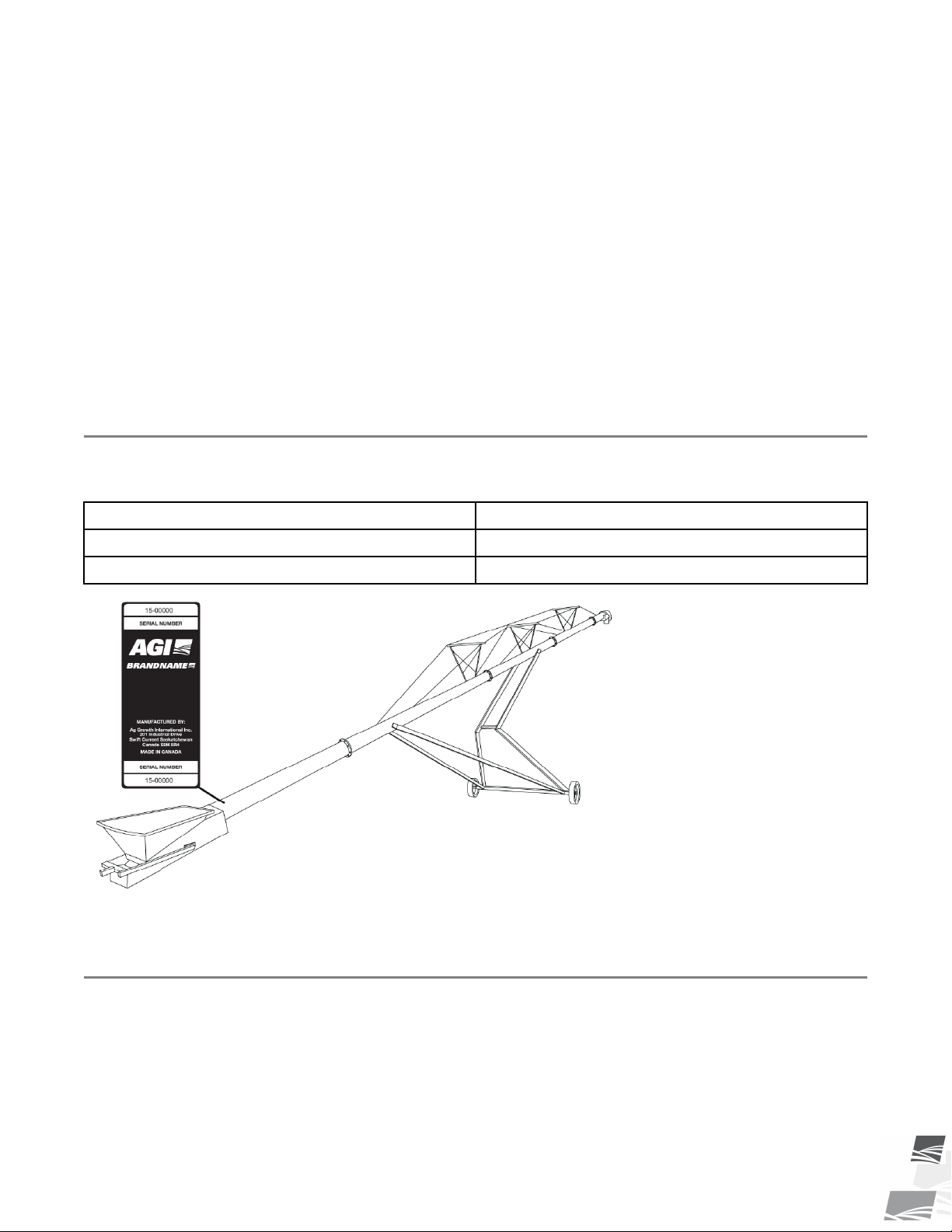
1.1. Serial Number Location
Always give your dealer the serial number on your conveyor (shown below) when ordering parts or requesting
service or other information. Please record this information in the table below for easy reference.
Model Number
Serial Number
Date Received
1.2. Intended Use
The conveyor is designed solely for use in the intended agricultural use as listed below. Use in any other way is
considered as contrary to the intended use. Compliance with and strict adherence to the conditions of
operation and maintenance as specified by the manufacturer, also constitute essential elements of the intended
use.
The conveyor should be operated, maintained, serviced, and repaired only by persons who are familiar with its
particular characteristics and who are acquainted with the relevant safety procedures.
P1512137 R3 5
Page 6

1. INTRODUCTION S-DRIVE STANDARD CONVEYOR – PORTABLE GRAIN BELT CONVEYOR
Accident prevention regulations and all other generally recognized regulations on occupational health and
safety must be observed at all times.
Any modifications made to the conveyor may relieve the manufacturer of liability for any resulting damage or
injury.
Intended use for the conveyor:
• Handling grain, pulse crops, treated seeds, or other similar materials.
• Handling fertilizer when strict operation and cleanout procedures are followed as noted in Operation
section.
Use in any other way is considered as contrary to the intended use and is not covered by the warranty.
1.2.1 Misuse
Do not use the conveyor for/with:
• transferring material other than dry, free-flowing food-grains.
• conveying canola, or any other oilseeds
• lifting or using as a hoist or crane.
6 P1512137 R3
Page 7

S-DRIVE STANDARD CONVEYOR – PORTABLE GRAIN BELT CONVEYOR 2. SAFETY
2. Safety
2.1. Safety Alert Symbol and Signal Words
This safety alert symbol indicates important safety messages in this manual. When you see
this symbol, be alert to the possibility of injury or death, carefully read the message that
follows, and inform others.
Signal Words: Note the use of the signal words DANGER, WARNING, CAUTION, and NOTICE with the safety
messages. The appropriate signal word for each message has been selected using the definitions below as a
guideline.
Indicates an imminently hazardous situation that, if not avoided, will result in serious injury or
death.
Indicates a hazardous situation that, if not avoided, could result in serious injury or death.
Indicates a hazardous situation that, if not avoided, may result in minor or moderate injury.
Indicates a potentially hazardous situation that, if not avoided, may result in property damage.
2.2. General Product Safety
YOU are responsible for the SAFE use and maintenance of your conveyor. YOU must ensure that you and
anyone else who is going to work around the conveyor understands all procedures and related SAFETY
information contained in this manual.
Remember, YOU are the key to safety. Good safety practices not only protect you, but also the people around
you. Make these practices a working part of your safety program. All accidents can be avoided.
• It is the conveyor owner, operator, and maintenance personnel's responsibility to
read and understand ALL safety instructions, safety decals, and manuals and follow
them when operating, or maintaining the equipment.
• Owners must give instructions and review the information initially and annually with all personnel before
allowing them to operate the conveyor. Untrained users/operators expose themselves and bystanders to
possible serious injury or death.
• The conveyor is not intended to be used by children.
• Use the conveyor for its intended purposes only.
• Do not modify the conveyor in any way without written permission from the manufacturer. Unauthorized
modification may impair the function and/or safety, and could affect the life of the conveyor. Any
unauthorized modification will void the warranty.
P1512137 R3 7
Page 8
2. SAFETY S-DRIVE STANDARD CONVEYOR – PORTABLE GRAIN BELT CONVEYOR
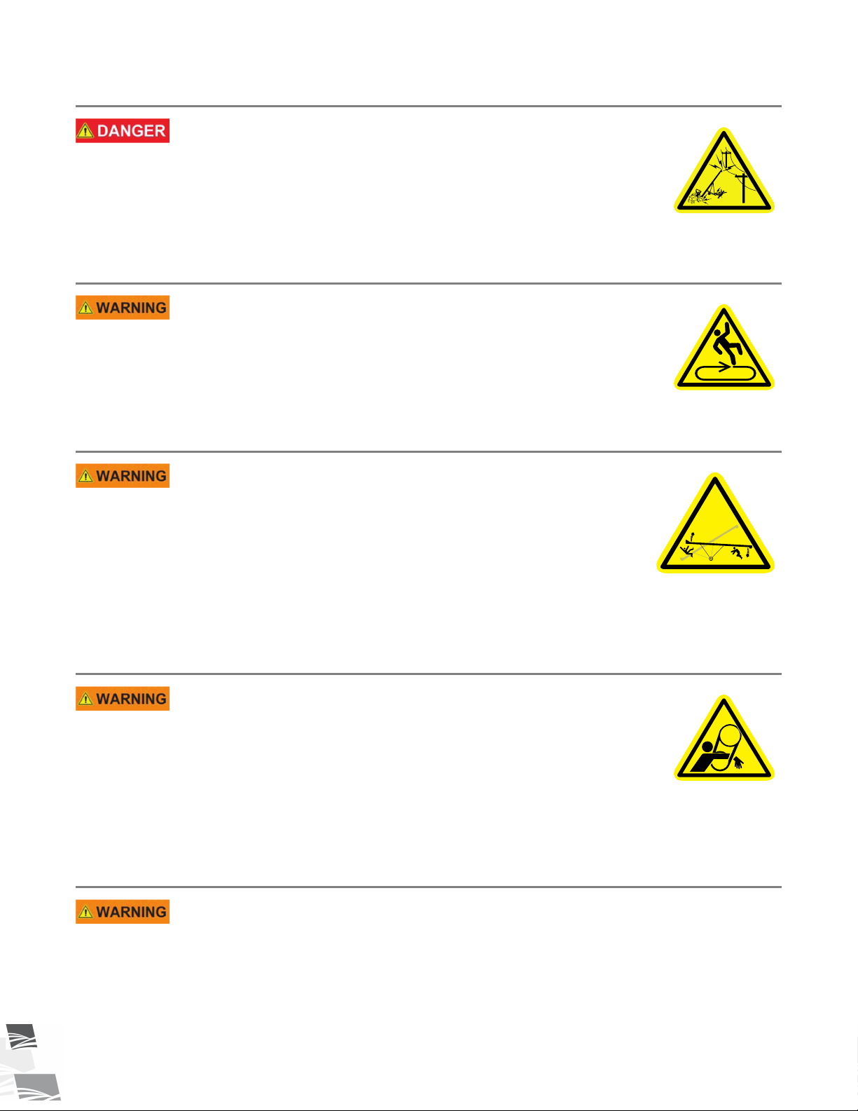
2.3. Overhead Power Lines
• When operating or moving, keep conveyor away from
overhead power lines and devices.
• The conveyor is not insulated.
• Electrocution can occur without direct contact.
2.4. Moving Conveyor Belt Safety
• DO NOT step on or touch moving conveyor belt.
• Shut off and lock out power to adjust, service, or clean.
2.5. Upending
• Anchor intake end and/or support discharge end to prevent
upending.
• Intake end must always have downward weight. Do not
release until attached to tow bar or resting on ground.
• Do not raise intake end above tow bar height.
• Empty the conveyor and fully lower before moving.
2.6. Rotating Parts Safety
• Keep body, hair, and clothing away from rotating pulleys,
belts, chains, and sprockets.
• Do not operate with any guard removed or modified. Keep
guards in good working order.
• Shut off and remove key or lock out power source before
inspecting or servicing machine.
2.7. Work Area Safety
• Have another trained person nearby who can shut down the conveyor in case of accident.
• The work area should be kept clear of bystanders.
• Keep the work area clean and free of debris.
8 P1512137 R3
Page 9
S-DRIVE STANDARD CONVEYOR – PORTABLE GRAIN BELT CONVEYOR 2. SAFETY
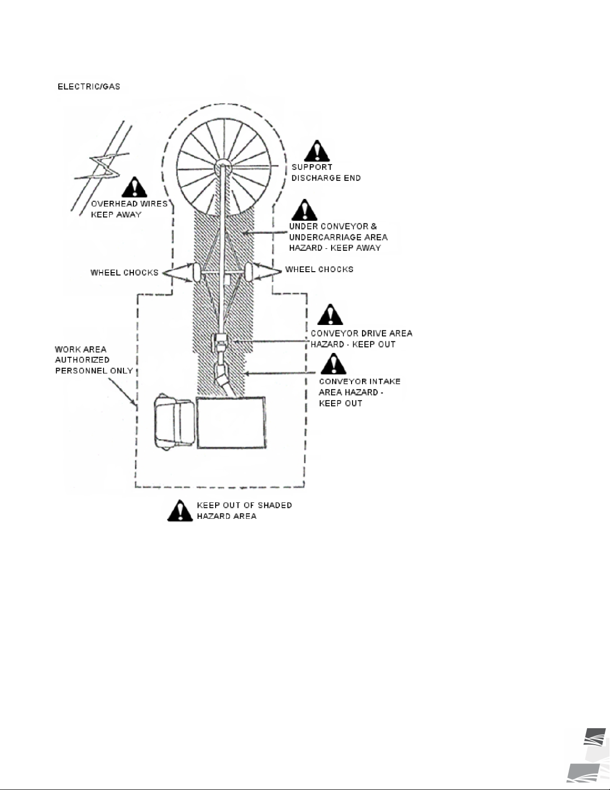
Figure 1. Conveyor Work Area (Gas/Electric Drive)
P1512137 R3 9
Page 10
2. SAFETY S-DRIVE STANDARD CONVEYOR – PORTABLE GRAIN BELT CONVEYOR
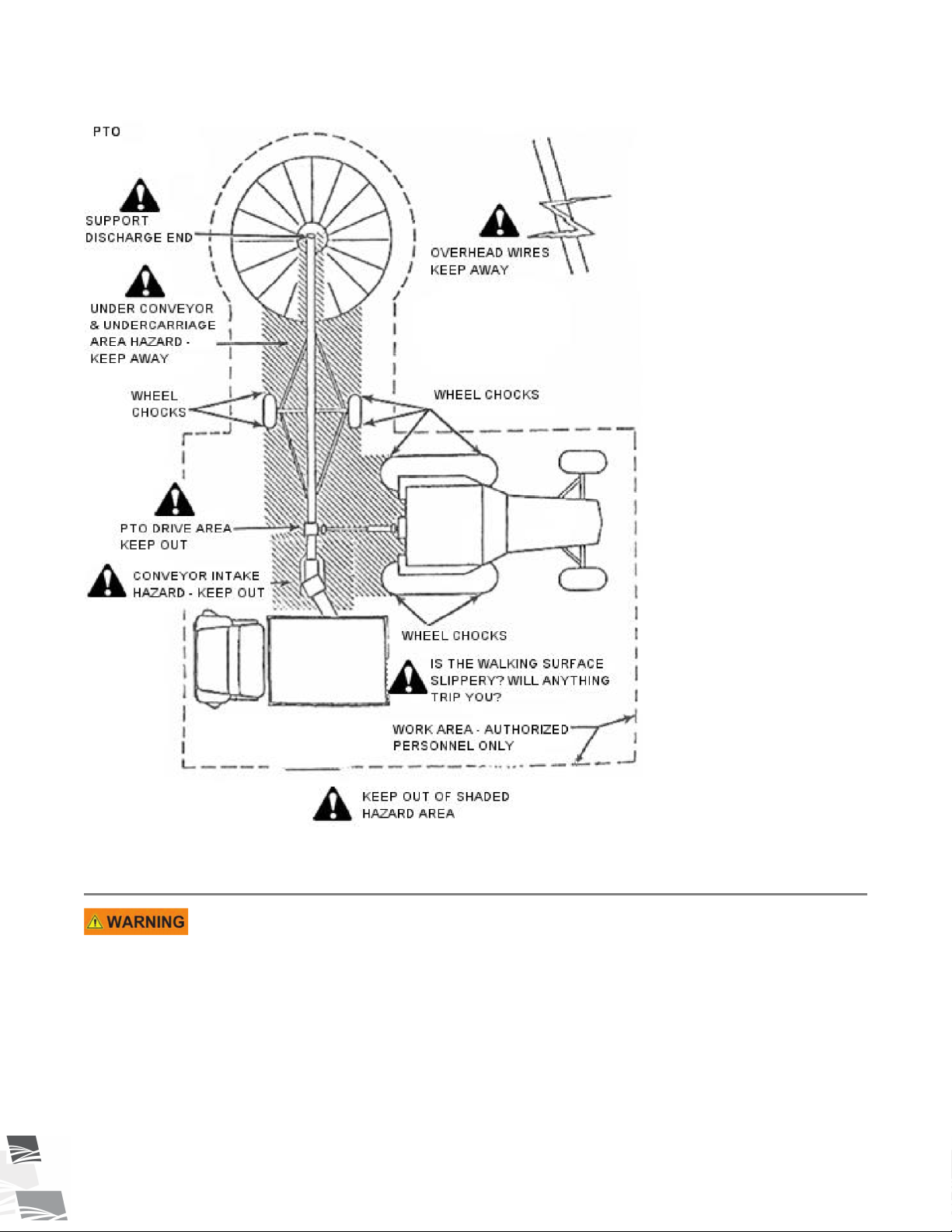
Figure 2. Conveyor Work Area (PTO Drive)
2.8. Guards Safety
• Keep guards in place and do not operate unless all guards are in place.
• Do not walk on, step on, or damage guards.
• Lock out power before removing a guard.
• Ensure all guards are replaced after performing maintenance.
10 P1512137 R3
Page 11

S-DRIVE STANDARD CONVEYOR – PORTABLE GRAIN BELT CONVEYOR 2. SAFETY
2.9. Raising and Lowering the Conveyor
• Before raising/lowering/moving/adjusting the conveyor, make sure the area around the
conveyor is clear of obstructions and/or untrained personnel. Never allow anyone to stand
on or beneath the conveyor when it is being placed.
• Lower the conveyor to its lowest position when not in use.
• Empty the conveyor before raising or lowering.
• Do not get on or beneath the conveyor when raising or lowering.
• Raise and lower conveyor on reasonably level ground only.
• Never attempt to increase height of the tube by positioning wheels on lumber, blocks, or by
any other means. To do so will result in damage to conveyor and/or serious injury.
• Do not raise the conveyor in high winds.
2.10. Positioning the Conveyor
• Transport and place equipment on reasonably level ground when raising, lowering,
positioning, or operating.
• Move the conveyor into position slowly. Do not unhitch and attempt to move by hand.
• Chock wheels and anchor intake end after placement.
2.11. Towing the Conveyor
The conveyor is not intended for transport on public roads. If it requires transport on a public roadway, the
following steps should be taken:
• Check with local authorities regarding transport on public roads. Obey all applicable laws
and regulations.
• Always travel at a safe speed, never exceeding 20 mph (32 km/h).
• Reduce speed on rough surfaces.
• Do not transport on slopes greater than 20°.
• Use caution when turning corners or meeting traffic.
• Make sure the SMV (slow moving vehicle) emblem and all the lights and reflectors that are
required by local authorities are in place, are clean, and can be seen by all over-taking and
oncoming traffic.
• Always use hazard-warning flashers on tractor/towing vehicle when transporting unless
prohibited by law.
• Do not allow riders on the conveyor or towing vehicle during transport.
• Attach to towing vehicle with an appropriate pin and retainer. Always attach safety chains.
• Place the conveyor in the transport position before moving on roads.
P1512137 R3 11
Page 12
2. SAFETY S-DRIVE STANDARD CONVEYOR – PORTABLE GRAIN BELT CONVEYOR
2.12. Drives and Lockout Safety
Inspect the power source(s) before using and know how to shut down in an emergency.
Whenever you service or adjust your equipment, make sure you shut down the power
source and unplug or remove the key (as applicable) to prevent inadvertent start-up and
hazardous energy release. Know the procedure(s) that applies to your equipment from the
following power source(s). Ensure that all personnel are clear before turning on power to
equipment.
2.12.1 Gas Engine Safety
Power Source
• Keep guards in place and secure.
• Properly ventilate surrounding area.
• Never fill the fuel tank with the engine running, while
smoking, or near an open flame. Always shut down and allow
engine to cool before filling with fuel.
• Never overfill the tank or spill fuel. If fuel is spilled, clean it
up immediately.
• Be sure to use the correct type and grade of fuel. Ground the
fuel funnel or nozzle against the filler neck to prevent sparks
that could ignite fuel vapors.
• Be sure to replace the fuel fill cap when you are done.
Lockout
• For engines with an electric start, remove the ignition key,
the spark plug wire, or the spark plug.
• For engines with a rope or crank start, remove the spark plug
wire or the spark plug.
12 P1512137 R3
Page 13
S E RV I C E D I S C O N N E C T
ON
OFF
S-DRIVE STANDARD CONVEYOR – PORTABLE GRAIN BELT CONVEYOR 2. SAFETY
2.12.2 Electric Motor Safety
Power Source
• Electric motors and controls shall be installed and serviced by
a qualified electrician and must meet all local codes and
standards.
• A magnetic starter should be used to protect your motor.
• You must have a manual reset button.
• Reset and motor starting controls must be located so that the
operator has full view of the entire operation.
• Locate main power disconnect switch within reach from
ground level to permit ready access in case of an emergency.
• Motor must be properly grounded.
• Guards must be in place and secure.
• Ensure electrical wiring and cords remain in good condition;
replace if necessary.
• Use a totally enclosed electric motor if operating in
extremely dusty conditions.
Lockout
• The main power disconnect switch should be in the locked position during shutdown or
whenever maintenance is performed.
• If reset is required, disconnect all power before resetting motor.
2.12.3 PTO Driveline Safety
Drive
• Keep body, hair, and clothing away from rotating PTO
driveline.
• Make certain the driveline shields telescope and rotate freely
on driveline before attaching.
• Make certain the driveline is securely attached at both ends.
• Do not operate conveyor unless all driveline, tractor, and
equipment shields are in place and in good working order.
• Do not exceed the specified operating speed.
• Keep universal joint angles small and equal. Do not exceed
maximum recommended length for PTO driveline.
• Engage tractor park brake and/or chock wheels.
P1512137 R3 13
Lockout
• Position all controls in neutral, shut off tractor’s engine, and remove key from tractor.
• If removing key is impossible, remove PTO driveline from tractor.
Page 14

2. SAFETY S-DRIVE STANDARD CONVEYOR – PORTABLE GRAIN BELT CONVEYOR
2.12.4 Hydraulic Power Safety
Power Source
• Refer to the rules and regulations applicable to the power
source operating your hydraulic drive.
• Do not connect or disconnect hydraulic lines while system is
under pressure.
• Keep all hydraulic lines away from moving parts and pinch
points.
• Escaping hydraulic fluid under pressure will cause serious
injury if it penetrates the skin surface (serious infection or
toxic reaction can develop). See a doctor immediately if
injured.
• Use metal or wood as a backstop when searching for
hydraulic leaks and wear proper hand and eye protection.
• Check all hydraulic components are tight and in good
condition. Replace any worn, cut, abraded, flattened, or
crimped hoses.
• Clean the connections before connecting to equipment.
• Do not attempt any makeshift repairs to the hydraulic fittings
or hoses with tape, clamps, or adhesive. The hydraulic
system operates under extremely high pressure; such repairs
will fail suddenly and create a hazardous and unsafe
condition.
Lockout
• Always place all hydraulic controls in neutral and relieve
system pressure before disconnecting or working on
hydraulic system.
14 P1512137 R3
Page 15
S-DRIVE STANDARD CONVEYOR – PORTABLE GRAIN BELT CONVEYOR 2. SAFETY
2.13. Tire Safety
Failure to follow proper procedures when mounting a tire on a
wheel or rim can produce an explosion that may result in
serious injury or death.
• DO NOT attempt to mount a tire unless you have the proper
equipment and experience to do the job.
• Have a qualified tire dealer or repair service perform
required tire maintenance.
• When replacing worn tires, make sure they meet the original
tire specifications. Never undersize the replacement tire.
• DO NOT weld to the tire rim with the tire mounted on the
rim. This action may cause an explosion which could result in
serious injury or death.
• Inflate tires to the manufacturer’s recommended pressure.
• Tires should not be operated at speeds higher than their
rated speed.
• Keep wheel lug nuts tightened to manufacturer’s
recommendations.
• Never reinflate a tire that has been run flat or seriously
under-inflated without removing the tire from the wheel.
Have the tire and wheel closely inspected for damage before
remounting.
2.14. Battery Safety
• Wear safety glasses and protective gloves when working near
batteries.
• Make certain the battery or terminal covers are in place and
in good working order.
• Keep all sparks and flames away from batteries; gas given off
by electrolyte is explosive.
• Avoid contact with battery electrolyte. Wash off any spilled
electrolyte immediately.
• Do not tip batteries more than 45° to avoid electrolyte loss.
• To avoid injury from sparks or short circuits, disconnect
battery ground cable before servicing any part of an electrical
system.
P1512137 R3 15
Page 16
2. SAFETY S-DRIVE STANDARD CONVEYOR – PORTABLE GRAIN BELT CONVEYOR
2.15. Personal Protective Equipment
The following Personal Protective Equipment (PPE) should be worn when operating or maintaining the
equipment.
Safety Glasses
• Wear safety glasses at all times to protect eyes from debris.
Coveralls
• Wear coveralls to protect skin.
Hard Hat
• Wear a hard hat to help protect your head.
Steel-Toe Boots
• Wear steel-toe boots to protect feet from falling debris.
Work Gloves
• Wear work gloves to protect your hands from sharp and rough edges.
Dust Mask
• Wear a dust mask to prevent breathing potentially harmful dust.
2.16. Safety Equipment
The following safety equipment should be kept on site:
Fire Extinguisher
• Provide a fire extinguisher for use in case of an accident. Store in a highly visible and
accessible place.
16 P1512137 R3
Page 17

S-DRIVE STANDARD CONVEYOR – PORTABLE GRAIN BELT CONVEYOR 2. SAFETY
First-Aid Kit
• Have a properly-stocked first-aid kit available for use should the need arise, and
know how to use it.
2.17. Safety Decals
• Keep safety decals clean and legible at all times.
• Replace safety decals that are missing or have become illegible. See decal location figures that follow.
• Replaced parts must display the same decal(s) as the original part.
• Replacement safety decals are available free of charge from your distributor, dealer, or factory as applicable.
2.17.1 Decal Installation/Replacement
1. Decal area must be clean and dry, with a temperature above 50°F (10°C).
2. Decide on the exact position before you remove the backing paper.
3. Align the decal over the specified area and carefully press the small portion with the exposed sticky backing
in place.
4. Slowly peel back the remaining paper and carefully smooth the remaining portion of the decal in place.
5. Small air pockets can be pierced with a pin and smoothed out using the sign backing paper.
2.17.2 Safety Decal Locations and Details
Replicas of the safety decals that are attached to the conveyor and their messages are shown in the figure(s)
that follow. Safe operation and use of the conveyor requires that you familiarize yourself with the various safety
decals and the areas or particular functions that the decals apply to, as well as the safety precautions that must
be taken to avoid serious injury, death, or damage.
P1512137 R3 17
Page 18
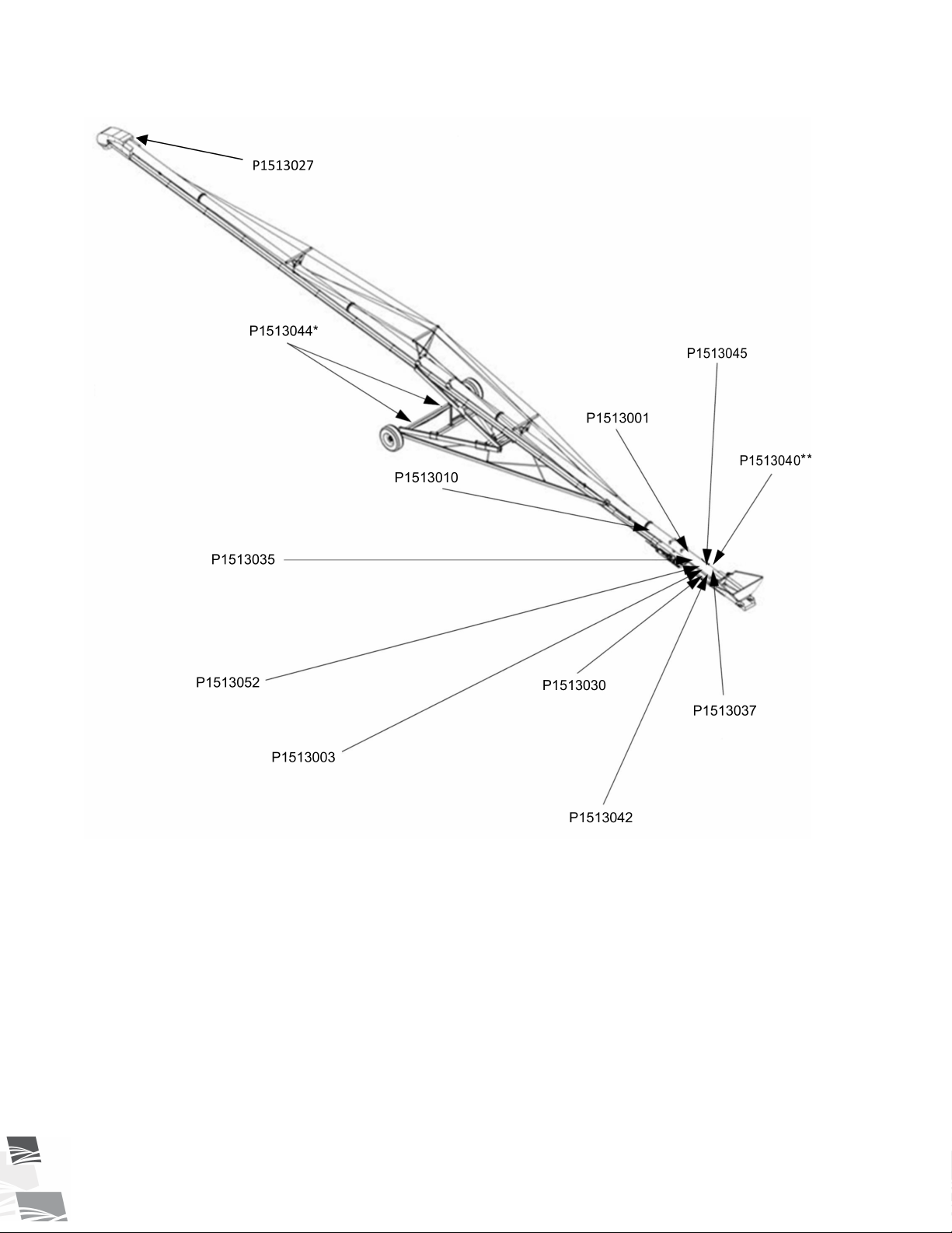
2. SAFETY S-DRIVE STANDARD CONVEYOR – PORTABLE GRAIN BELT CONVEYOR
Figure 3. Scissor-Lift Conveyor Safety Decal Locations
* if equipped with retractable axles
** if equipped with Mover Kit
18 P1512137 R3
Page 19
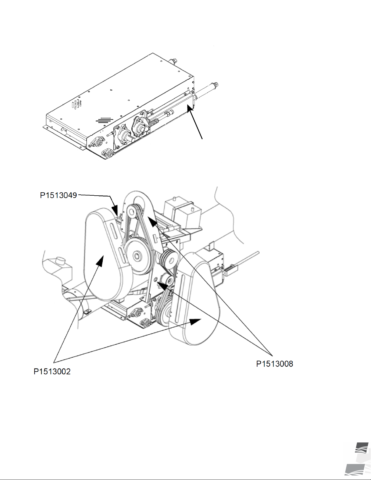
P1513061
S-DRIVE STANDARD CONVEYOR – PORTABLE GRAIN BELT CONVEYOR 2. SAFETY
Figure 4. S-Drive Safety Decal Locations
Figure 5. Gas Drive Safety Decal Locations
P1512137 R3 19
Page 20
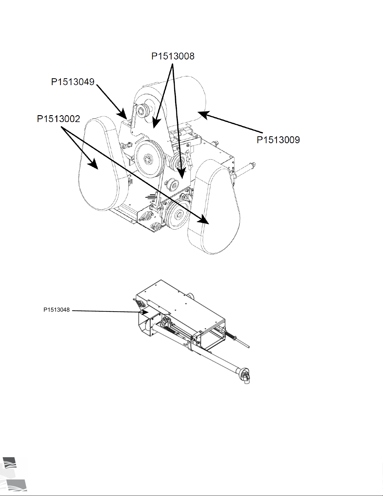
P1513048
2. SAFETY S-DRIVE STANDARD CONVEYOR – PORTABLE GRAIN BELT CONVEYOR
Figure 6. Electric Drive Safety Decal Locations
Figure 7. Side PTO Drive Safety Decal Locations
20 P1512137 R3
Page 21
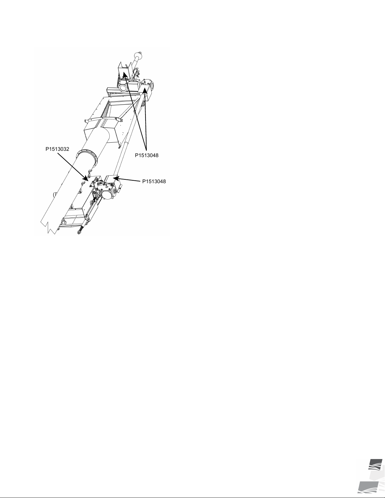
P1513032
P1513048
P1513048
S-DRIVE STANDARD CONVEYOR – PORTABLE GRAIN BELT CONVEYOR 2. SAFETY
Figure 8. Front PTO Drive Safety Decal Locations
P1512137 R3 21
Page 22
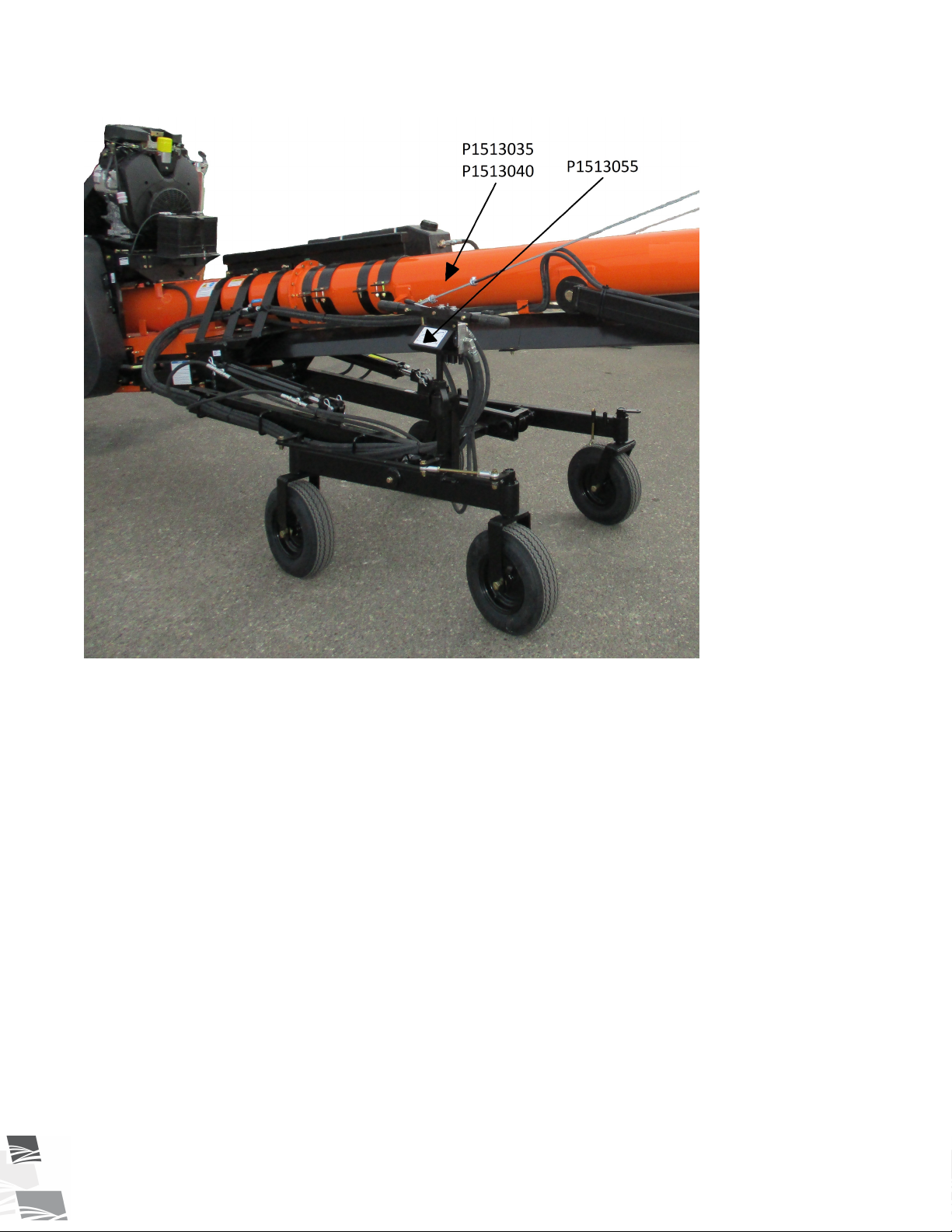
2. SAFETY S-DRIVE STANDARD CONVEYOR – PORTABLE GRAIN BELT CONVEYOR
Figure 9. Wheel Move Kit for S-Drive Standard Conveyor (1500–Series) — Decal Locations
22 P1512137 R3
Page 23
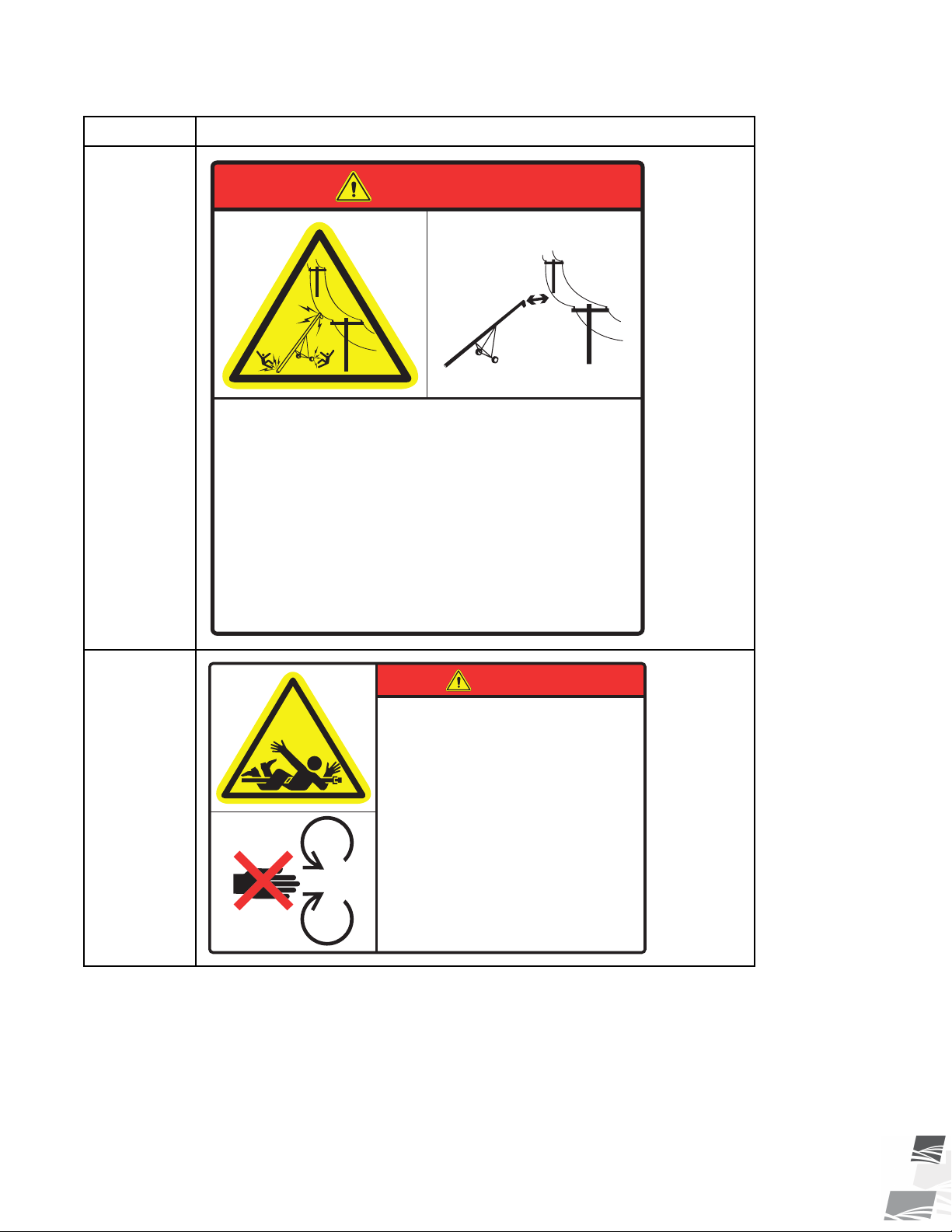
To prevent death or serious injury:
• When operating or moving, keep equipment away from
overhead power lines and devices.
• Fully lower equipment before moving.
This equipment is not insulated.
Electrocution can occur without direct contact.
ELECTROCUTION HAZARD
DANGER
DANGER
To prevent serious injury or death:
• Keep body, hair, and clothing away from rotating
PTO driveline.
• Do not operate equipment unless all driveline,
tractor, and equipment shields are in place and in
good working order.
• Make certain the driveline shields turn freely on
driveline.
• Make certain the driveline is securely attached at
both ends.
• Do not exceed specified operating speed (see
operator’s manual).
• Keep u-joint angles small and equal. Do not exceed
maximum recommended length for PTO driveline.
ROTATING PTO DRIVELINE
HAZARD
S-DRIVE STANDARD CONVEYOR – PORTABLE GRAIN BELT CONVEYOR 2. SAFETY
Table 1. Safety Decals
Part Number
P1513003
Description
P1513048
P1512137 R3 23
Page 24
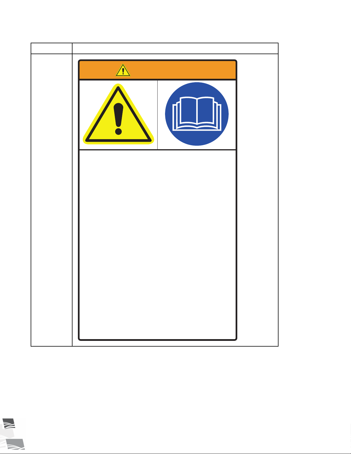
To prevent serious injury or death:
• Read and understand the manual before
assembling, operating, or maintaining the
equipment.
• Only trained personnel may assemble, operate,
or maintain the equipment.
• Children and untrained personnel must be kept
outside of the work area.
• Do not modify the equipment. Keep in good
working order.
• If the manual, guards, or decals are missing or
damaged, contact factory or dealer for
replacements.
• Lock out power before performing maintenance.
• To prevent equipment collapse, support equipment
tube while disassembling certain components.
• Electric motors must be grounded. Disconnect
power before resetting overloads.
WARNING
2. SAFETY S-DRIVE STANDARD CONVEYOR – PORTABLE GRAIN BELT CONVEYOR
Table 1 Safety Decals (continued)
Part Number
P1513001
Description
24 P1512137 R3
Page 25
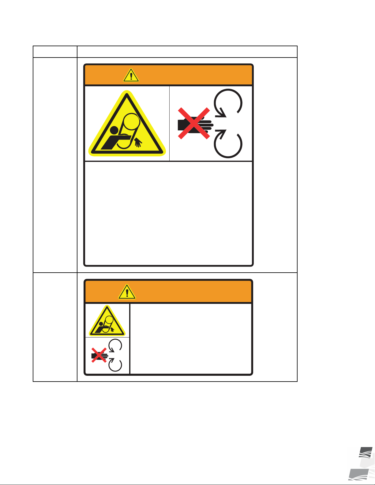
To prevent serious injury or death:
• Keep body, hair, and clothing away from rotating
pulleys, belts, chains, and sprockets.
• Do not operate with any guard removed or
modified. Keep guards in good working order.
• Shut off and remove key or lock out power
source before inspecting or servicing machine.
ENTANGLEMENT HAZARD
WARNING
To prevent serious injury or
death, shut off power and
reattach guard before operating
machine.
MISSING GUARD HAZARD
WARNING
S-DRIVE STANDARD CONVEYOR – PORTABLE GRAIN BELT CONVEYOR 2. SAFETY
Table 1 Safety Decals (continued)
Part Number
P1513002
Description
P1513008
P1512137 R3 25
Page 26
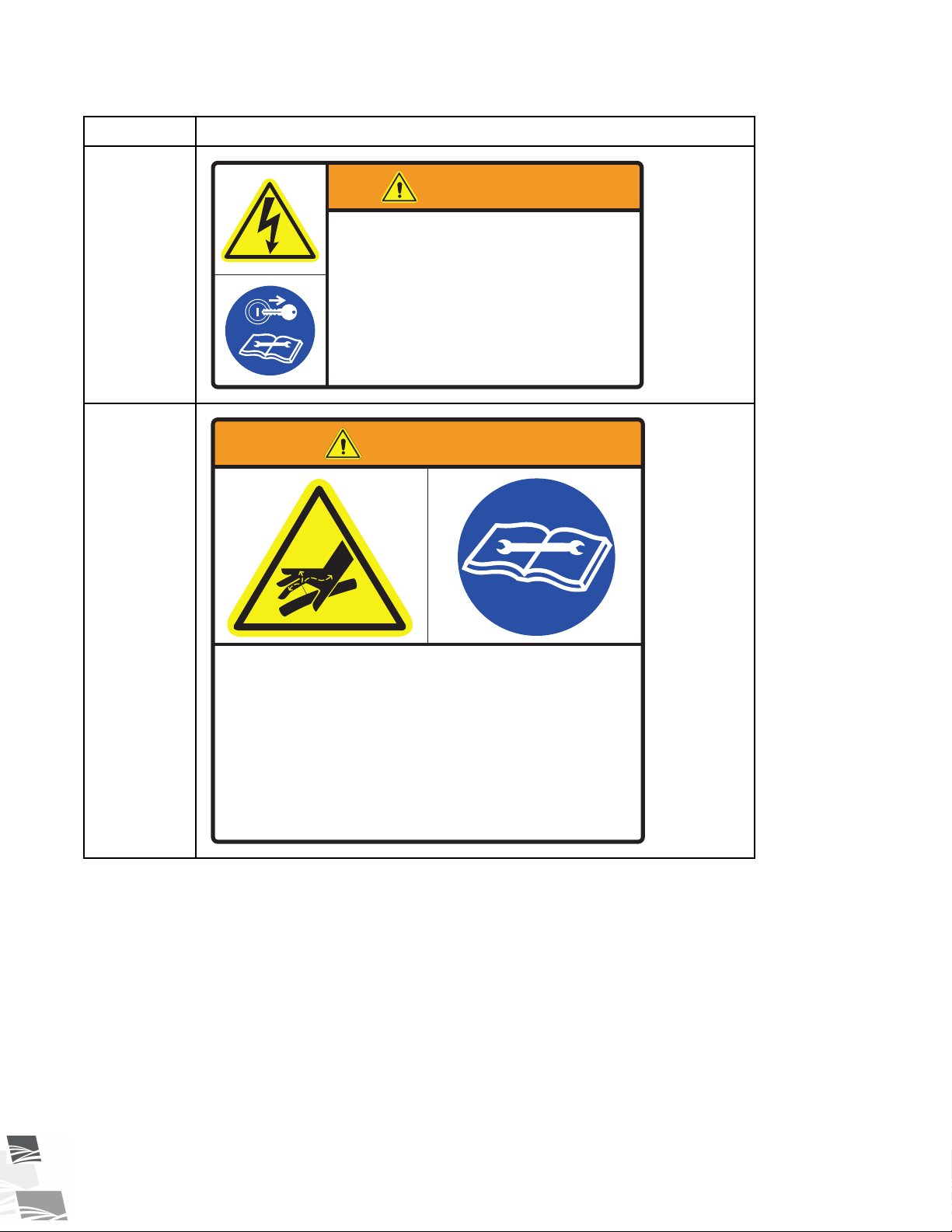
To prevent serious injury or death:
• Only qualified personnel should service
electrical components.
• Disconnect and lockout power before
inspecting or servicing unit.
• Keep electrical components in good repair.
ELECTROCUTION HAZARD
WARNING
Hydraulic fluid can cause serious injury if it
penetrates the skin. If it does, see a doctor
immediately.
• Relieve system pressure before repairing, adjusting or
disconnecting.
• Wear proper hand and eye protection when searching
for leaks. Use wood or cardboard instead of hands.
Hydraulic fluid can cause serious injury if it
penetrates the skin. If it does, see a doctor
immediately.
• Relieve system pressure before repairing, adjusting or
disconnecting.
• Wear proper hand and eye protection when searching
for leaks. Use wood or cardboard instead of hands.
HIGH PRESSURE FLUID HAZARD
WARNING
2. SAFETY S-DRIVE STANDARD CONVEYOR – PORTABLE GRAIN BELT CONVEYOR
Table 1 Safety Decals (continued)
Part Number
P1513009
P1513035
Description
26 P1512137 R3
Page 27
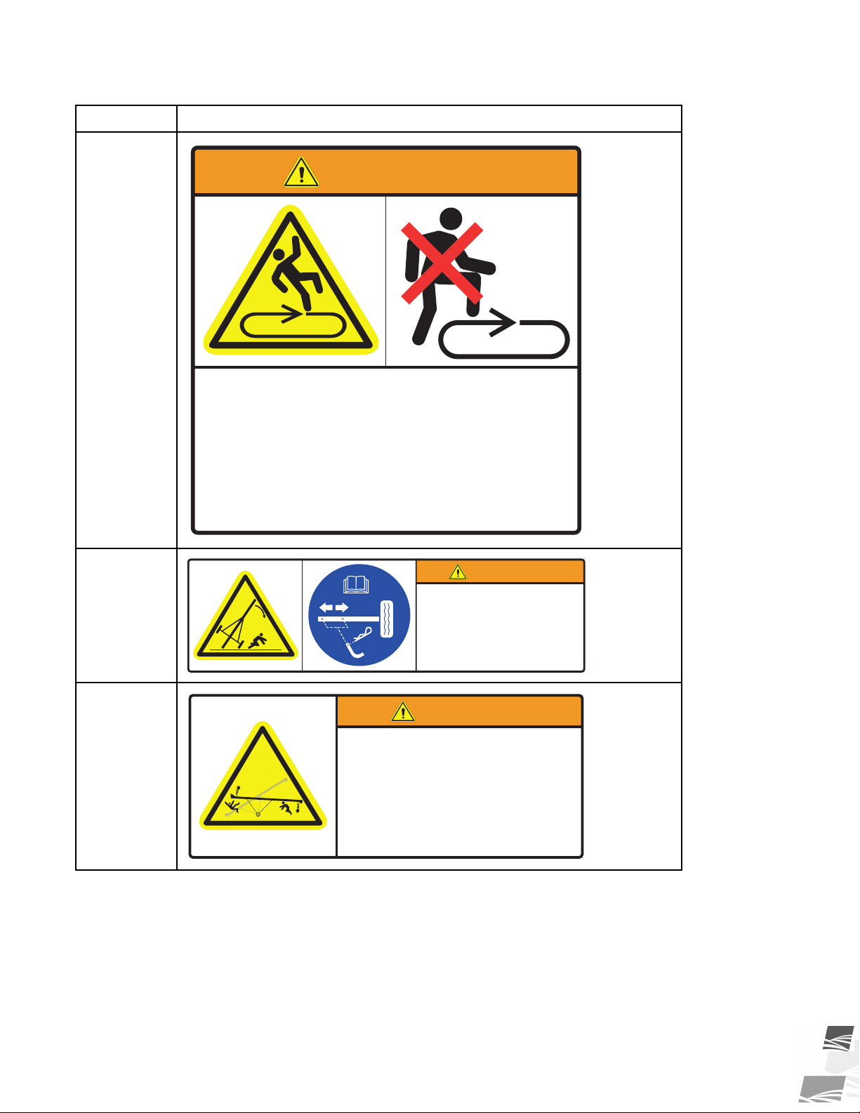
To prevent death or serious injury:
• DO NOT step on or touch moving conveyor belt.
• Shut off and lock out power to adjust, service, or
clean.
OPEN BELT CONVEYOR
WARNING
To prevent serious injury or death:
• Fully extend axles before raising tube.
• Retract axles before transporting.
ROLLOVER / TRANSPORT
HAZARD
WARNING
To prevent death or serious injury:
• Anchor intake end and/or support discharge end to
prevent upending.
• Intake end must always have downward weight. Do not
release until attached to tow bar or resting on ground.
• Do not raise intake end above tow bar height.
• Empty conveyor and fully lower before moving.
UPENDING HAZARD
WARNING
S-DRIVE STANDARD CONVEYOR – PORTABLE GRAIN BELT CONVEYOR 2. SAFETY
Table 1 Safety Decals (continued)
Part Number
P1513045
Description
P1513044
P1513042
P1512137 R3 27
Page 28
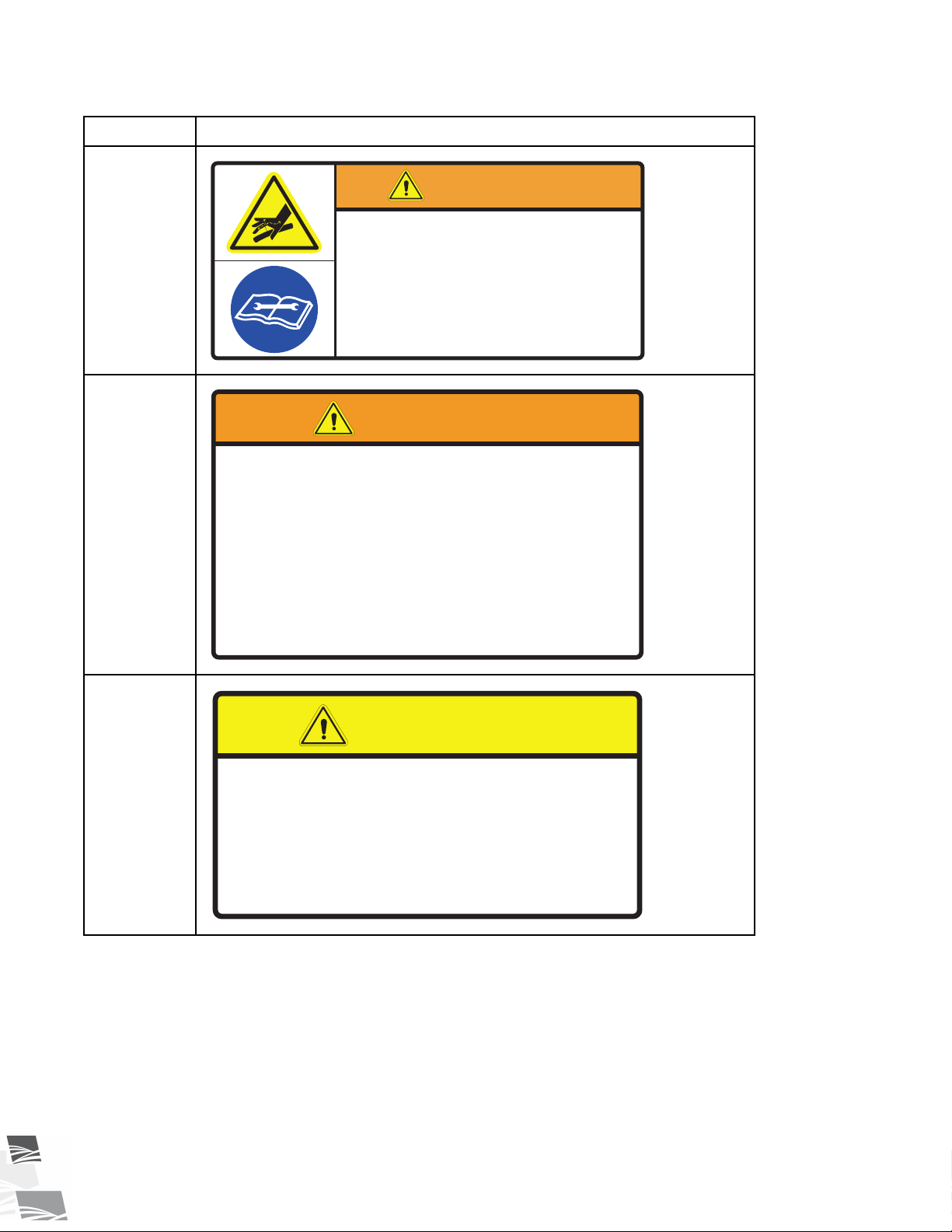
HIGH PRESSURE FLUID HAZARD
Hydraulic fluid can cause serious injury if it
penetrates the skin. If it does, see a doctor
immediately.
• Relieve system pressure before repairing, adjusting
or disconnecting.
• Wear proper hand and eye protection when searching
for leaks. Use wood or cardboard instead of hands.
WARNING
To prevent serious injury or equipment
damage, before towing:
• Lift up wheel frame completely and secure with
safety chain.
• Pull handle to disengage drive wheel motors.
TRANSPORT HAZARD
WARNING
To prevent personal injury or
damage to equipment, close valve
in lift cylinder hydraulic line after
raising equipment into position.
CAUTION
2. SAFETY S-DRIVE STANDARD CONVEYOR – PORTABLE GRAIN BELT CONVEYOR
Table 1 Safety Decals (continued)
Part Number
P1513036
P1513040
Description
P1513010
28 P1512137 R3
Page 29
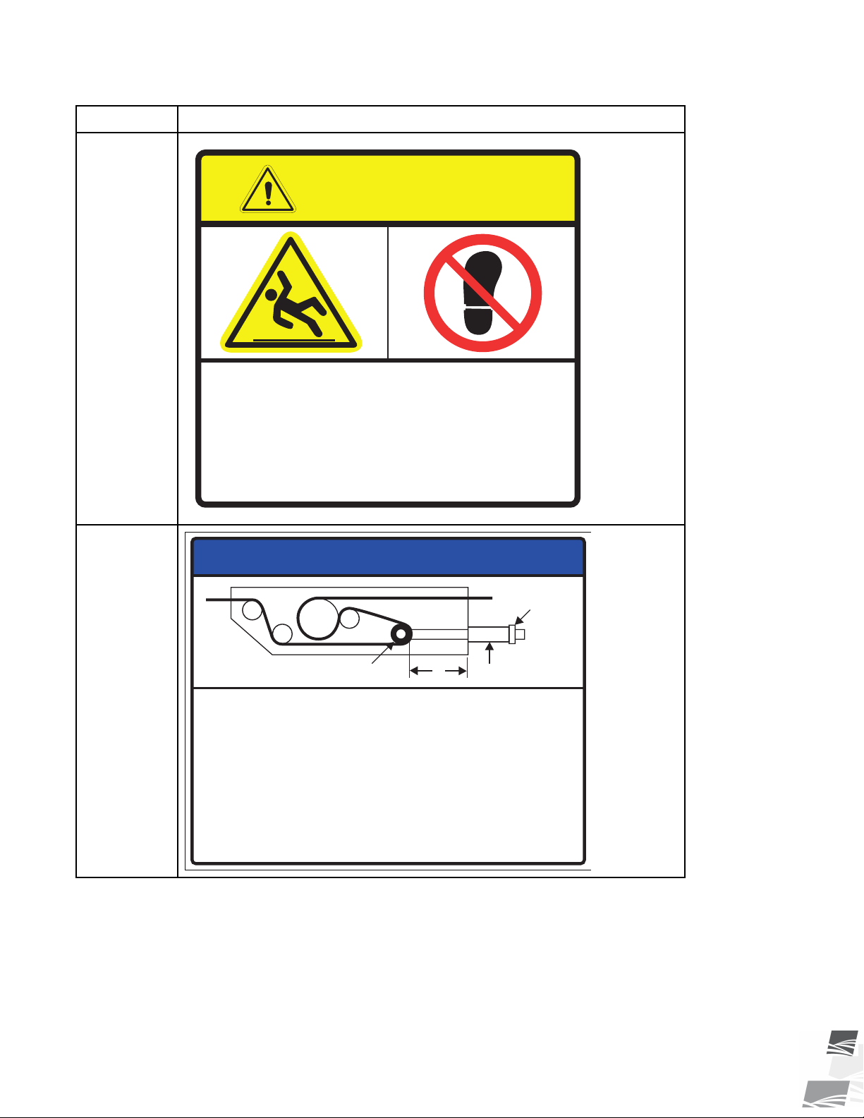
To prevent injury or damage to the
equipment, do not use belt guard as
a step.
NOT A STEP - SLIP HAZARD
CAUTION
PRETENSIONER
NUT
TAKE-UP ROLLER
X
To prevent belt damage, use correct belt tension and do not
attempt to adjust belt tracking with the take-up roller.
To set correct belt tension:
• While conveyor is running empty, tighten nut against the pretensioner
(take-up pipe) so that the edge of the indicator pipe is within the green area.
• Ensure take-up roller is tensioned equally by using a tape to measure
distance “X”.
• After the conveyor belt has been tensioned, check the alignment of all
other s-drive rollers and periodically afterward.
See manual for complete instructions.
NOTICE
S-DRIVE STANDARD CONVEYOR – PORTABLE GRAIN BELT CONVEYOR 2. SAFETY
Table 1 Safety Decals (continued)
Part Number
P1513030
Description
P1513061
P1512137 R3 29
Page 30
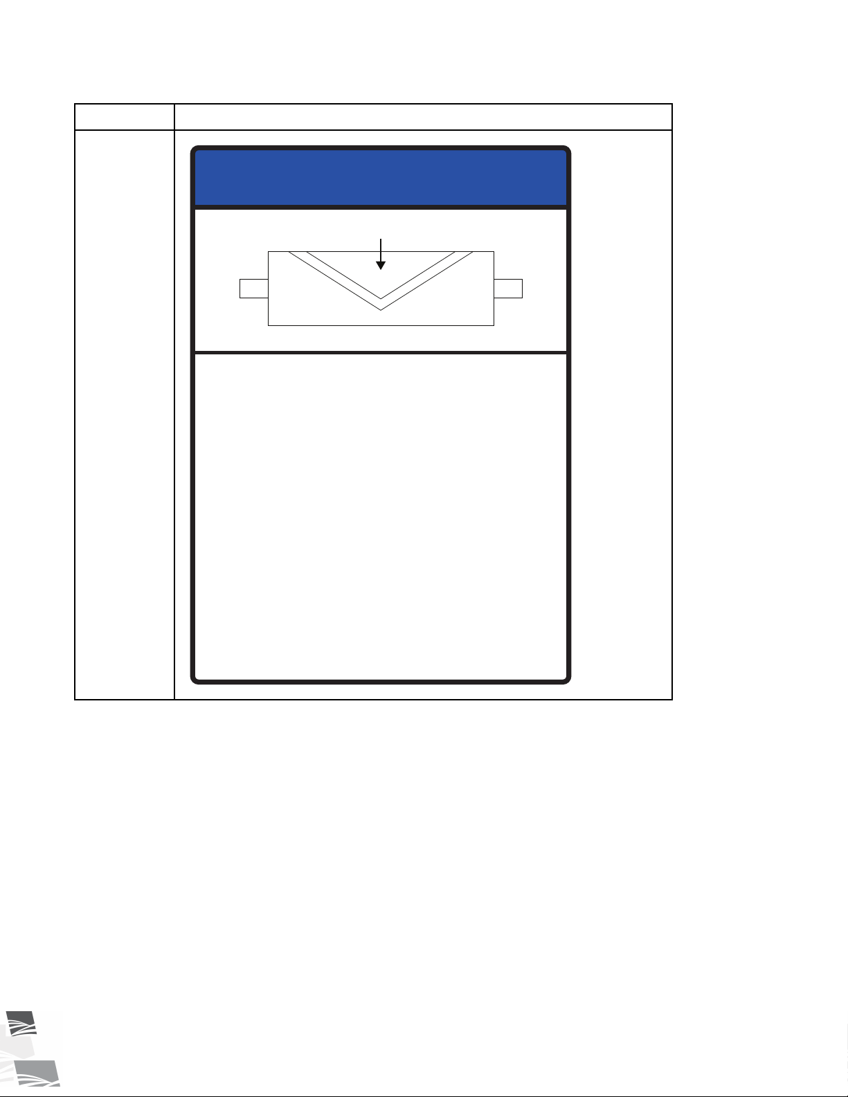
To prevent damage to the belt
and roller:
• Install roller with roller lagging
pointing in the direction of belt travel.
• Annually inspect condition of roller,
lagging and belt.
• Ensure that you do not run a
machine with loose lagging, or the
conveyor belt may become
damaged.
NOTICE
Belt Direction
2. SAFETY S-DRIVE STANDARD CONVEYOR – PORTABLE GRAIN BELT CONVEYOR
Table 1 Safety Decals (continued)
Part Number
P1513027
Description
30 P1512137 R3
Page 31
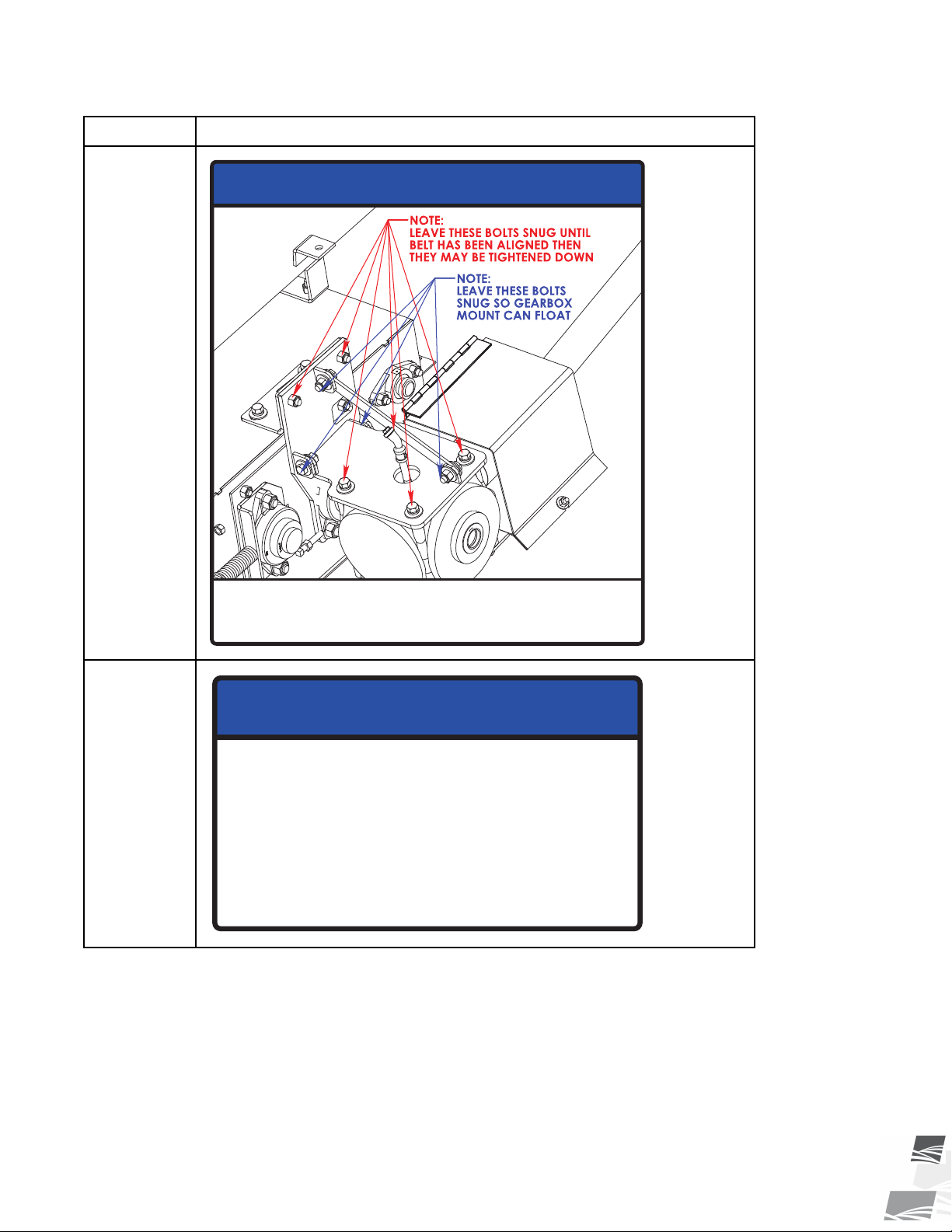
To prevent damage, tighten/snug bolts as shown
when assembling or maintaining the conveyor.
NOTICE
To prevent damage, wheels must be
free to move when raising or lowering
equipment.
When equipment is positioned, chock
all wheels.
NOTICE
S-DRIVE STANDARD CONVEYOR – PORTABLE GRAIN BELT CONVEYOR 2. SAFETY
Table 1 Safety Decals (continued)
Part Number
P1513032
Description
P1513052
P1512137 R3 31
Page 32
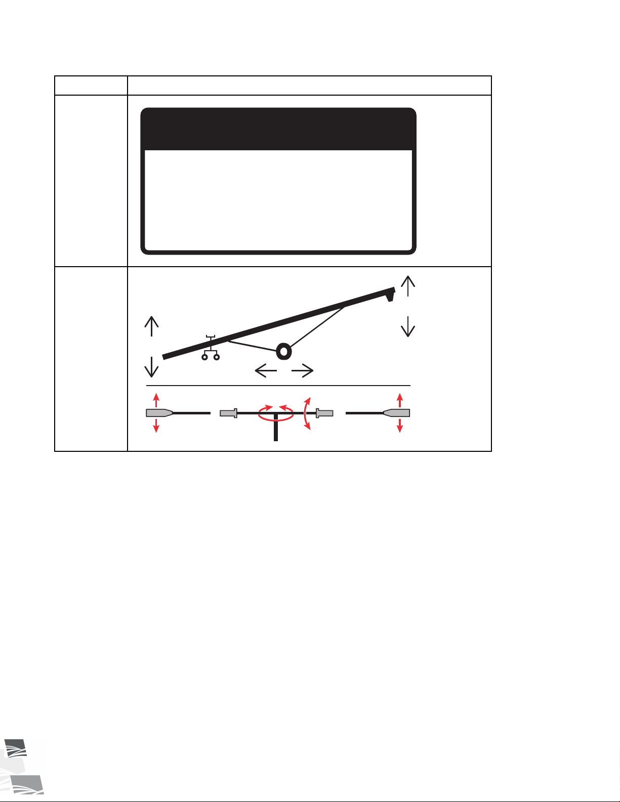
Lubricate belt release
and motor mount sliders
with silicone or light oil.
IMPORTANT
1
4
3 2
4
2
3
1
2. SAFETY S-DRIVE STANDARD CONVEYOR – PORTABLE GRAIN BELT CONVEYOR
Table 1 Safety Decals (continued)
Part Number
P1513049
P1513055
Description
32 P1512137 R3
Page 33
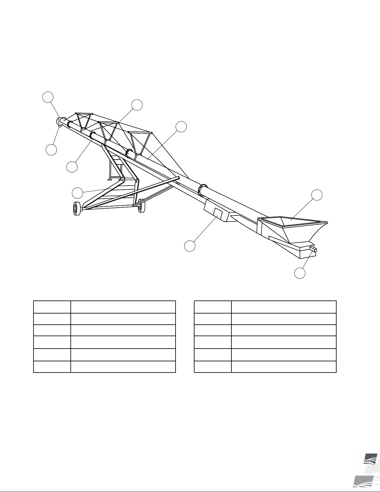
1
3
9
5
4
6
2
10
7
S-DRIVE STANDARD CONVEYOR – PORTABLE GRAIN BELT CONVEYOR 3. FEATURES
3. Features
This section covers the main features of the conveyor.
Figure 10. Typical S-Drive Standard Conveyor Components (Scissor-Lift Conveyor)
Table 2. Typical S-Drive Standard Conveyor Components (Scissor-Lift Conveyor)
Item
1
2
Tube
Scissor Frame
3 Hopper 8
4
5
P1512137 R3 33
Spout Assembly
Hood
Description
Item
6
7
Belt Return and Weather Guard
Hitch
Description
Jack (not shown)
9
Cable Truss
10 S-Drive
Page 34

3. FEATURES S-DRIVE STANDARD CONVEYOR – PORTABLE GRAIN BELT CONVEYOR
3.1. Model Number
34 P1512137 R3
Page 35

S-DRIVE STANDARD CONVEYOR – PORTABLE GRAIN BELT CONVEYOR 4. TRANSPORT
4. Transport
Before continuing, ensure you have completely read and understood this manual’s
Safety section, in addition to the safety information in the section(s) below.
4.1. Transport Safety
• Check with local authorities regarding transport on public roads. Obey all applicable laws
and regulations.
• Always travel at a safe speed, never exceeding 20 mph (32 km/h). Reduce speed on rough
surfaces. Use caution when turning corners or meeting traffic.
• Yield to other drivers and allow faster traffic to pass.
• Make sure the SMV (slow moving vehicle) emblem and all the lights and reflectors that are
required by local authorities are in place, are clean, and can be seen by all over-taking and
oncoming traffic. Always use hazard-warning flashers on tractor/towing vehicle when
transporting unless prohibited by law.
• Do not transport during times of limited visibility such as fog, snow, or heavy rain. Take extra
precautions at night and at dusk.
• Keep others away from the transport vehicle and conveyor.
• Do not allow riders on the conveyor or towing vehicle during transport.
• Stay away from overhead obstructions and power lines when operating and transporting.
Electrocution can occur without direct contact.
• Fully lower the conveyor before transporting, and only raise when next to storage facility.
• Attach to a proper towing vehicle with a pin and retainer. Always attach safety chain(s).
• Do not raise the intake end above drawbar, upending may occur.
• Empty conveyor of all grain before transporting. Transporting a full conveyor will place
excessive loads on the tube, frame, axle, hitch, and tow vehicle.
• Do not transport on slopes greater than 20°.
• Do not transport with an under-inflated tire(s).
• If the conveyor wheels are partially or fully buried in snow or grain, failure to clear area
around the wheels before transporting may cause damage to the conveyor or result in
serious injury.
4.2. Transport Preparation
1. It is not recommended that the conveyor be transported faster than 20 mph (32 km/h). Table 3 references
the acceptable transport speed as per the ratio of tractor weight versus conveyor weight. See Specifications
for conveyor weights.
A weight imbalance between the and the towing vehicle could result in a collision from
reduced stability, handling, and braking ability.
2. Ensure the conveyor will clear any overhead obstructions or electrical wires prior to transporting. Refer to
Specifications for the transport height of your conveyor.
P1512137 R3 35
Page 36

4. TRANSPORT S-DRIVE STANDARD CONVEYOR – PORTABLE GRAIN BELT CONVEYOR
3. Longer conveyors have a large turning radius. Allow ample room for turning as the discharge end may swing
dramatically. Allow all oncoming traffic to pass before turning right or left.
A collision with an oncoming vehicle could occur if the conveyor discharge swings into the
opposing lane.
Table 3. Speed versus Weight Ratio
Weight or fully equipped or loaded implement(s)
Road Speed
relative to weight of towing machine
Up to 32 km/h (20 mph)
Up to 16 km/h (10 mph)
Do not tow if More than 2 to 1
1 to 1, or less
2 to 1, or less
4.3. Connect the Conveyor to the Towing Vehicle
This section provides and overview of how to connect the conveyor to the towing vehicle. For specific
information on the components, refer to the applicable section.
Follow all safety precautions when transporting the conveyor and use a proper towing vehicle.
1. Fully lower the conveyor, there should be slight tension on the lift cable.
2. Connect the conveyor to the two vehicle with a hitch pin. Use a hitch pin that will not allow the conveyor to
separate from the towing vehicle.
3. Connect the safety chain securely, forming a cradle to prevent the conveyor from digging into the road
surface (should a breakaway occur). Do not use the safety chain if one or more links or end fittings are
stretched, broken, damaged, or deformed.
Important
The safety chain should have a load rating at least as high as the conveyor weight.
4. Use caution when transporting the conveyor over rolling terrain. In severe dips, the intake end may contact
the ground.
Refer to Section 9. – Specifications on page 71 for conveyor weight and hitch pin information.
36 P1512137 R3
Page 37

S-DRIVE STANDARD CONVEYOR – PORTABLE GRAIN BELT CONVEYOR 5. PLACEMENT
5. Placement
Before continuing, ensure you have completely read and understood this manual’s
Safety section, in addition to the safety information in the section(s) below.
5.1. Placement Safety
• The conveyor is not insulated, keep away from overhead power lines. Electrocution can
occur without direct contact.
• Anchor intake end before using.
• Place the conveyor on reasonably level ground before operating. The conveyor could topple
if ground is too uneven.
• Chock the conveyor wheels after placement.
• Empty the conveyor before raising, lowering, or positioning.
• Check that wheels are free to move before raising or lowering the conveyor.
• Never attempt to increase height of the conveyor by positioning wheels on lumber, blocks,
or by any other means.
• Do not permit anyone to stand beneath the conveyor when raising or lowering.
• Move the conveyor into position slowly. Do not unhitch and attempt to move by hand.
• Do not leave tube in raised position when not in use.
5.2. Positioning the Conveyor
To position the conveyor using a tractor:
Filling Bins
1. Back the conveyor up to the bin while it is in its lowered configuration.
2. Set the park brake on the tractor before dismounting.
3. Raise the conveyor so it clears the bin.
4. Slowly back the conveyor up until the outlet is over the opening in the bin.
5. Unhook the conveyor from the tractor and lower the intake end to the ground.
Upending hazard, do not hook or unhook hitch unless weight is down.
6. Slowly lower the conveyor spout to the bin.
Do not rest the spout or hood on the bin. This may cause hood or belt damage.
7. Remove the hitch from the conveyor to prevent interfering with other equipment.
8. Place chocks in the front and back of each wheel and anchor the intake end.
P1512137 R3 37
Page 38
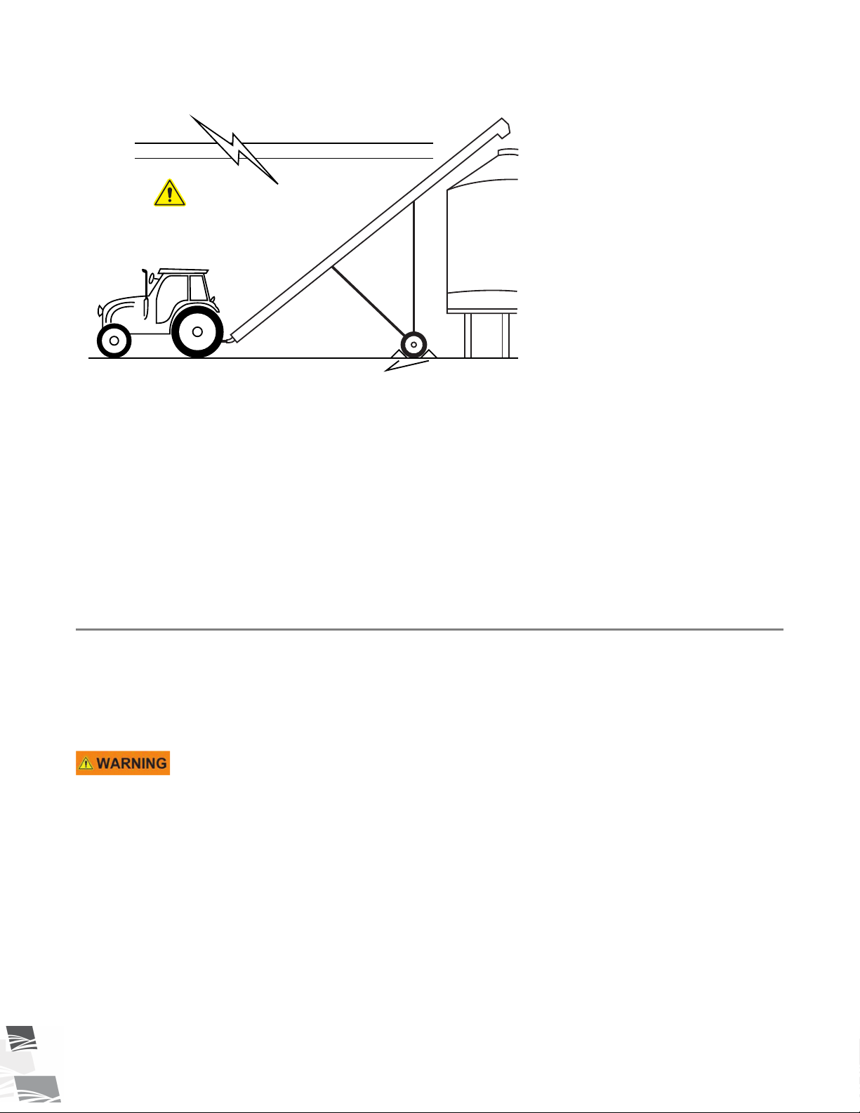
KEEP AWAY!
OVERHEAD WIRES
wheel chocks
Æ
5. PLACEMENT S-DRIVE STANDARD CONVEYOR – PORTABLE GRAIN BELT CONVEYOR
Figure 11. Typical Grain Conveyor Placement for Filling Bins
Under Hopper Bottom Bins
1. Center the conveyor between the hopper bin’s vertical legs.
2. Collapse the cloth hopper until the conveyor is fully positioned under the bin.
3. Move the conveyor into place. Do not allow the conveyor tube or components to contact the bin.
4. Raise the conveyor to the desired height.
5. Make sure that gravel is not jammed against the belt under the hopper.
6. Place chocks in the front and back of each wheel and anchor the intake end.
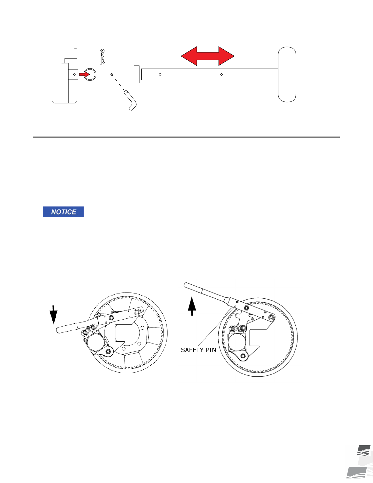
5.3. Extendable Axle Positioning
When equipped with extendable axles:
Important
Do not raise the conveyor unless the axles are in the extended position. Do not transport the conveyor
unless the axles are in the retracted position.
Rollover can occur if axles are not extended before raising the conveyor.
1. Ensure the conveyor is on level ground before attempting to extend or retract the axles. The conveyor must
be attached to tractor at all times.
2. Using the jack supplied, insert it into one of the jack stubs located on one end of the axle. Jack must be
secured to jack stub using pin (attached to jack).
3. Raise one side at a time. Raise until the tire clears the ground.
4. Remove the axle pin from the axle and position the axle as desired until the holes line up. Reinsert the axle
pin and secure with hairpin. Lower the jack.
5. Repeat the process on the opposite side of the axle.
38 P1512137 R3
Page 39
Æ
S-DRIVE STANDARD CONVEYOR – PORTABLE GRAIN BELT CONVEYOR 5. PLACEMENT
Figure 12. Typical Extendable Axle
5.4. Positioning the Conveyor with a Wheel Move Kit
When equipped with a Wheel Move Kit:
Before Operating the Wheel Move Kit:
• Ensure the area around the conveyor is reasonably level and there is adequate clearance for making wide
turns.
• Check the hydraulic oil to ensure that the levels are correct.
Running the machine on low oil will overheat the system causing components to break
down.
To Operate the Wheel Move Kit:
1. Engage the over-center handle at each wheel (Figure 13 on page 39) and check that the gears are fully
meshed. If necessary, refer to Pinion Gear Adjustment section.
Figure 13. Wheel Over-Center Handle Positions
Engaged Disengaged
2. Set and run the gas engine at approximately half throttle.
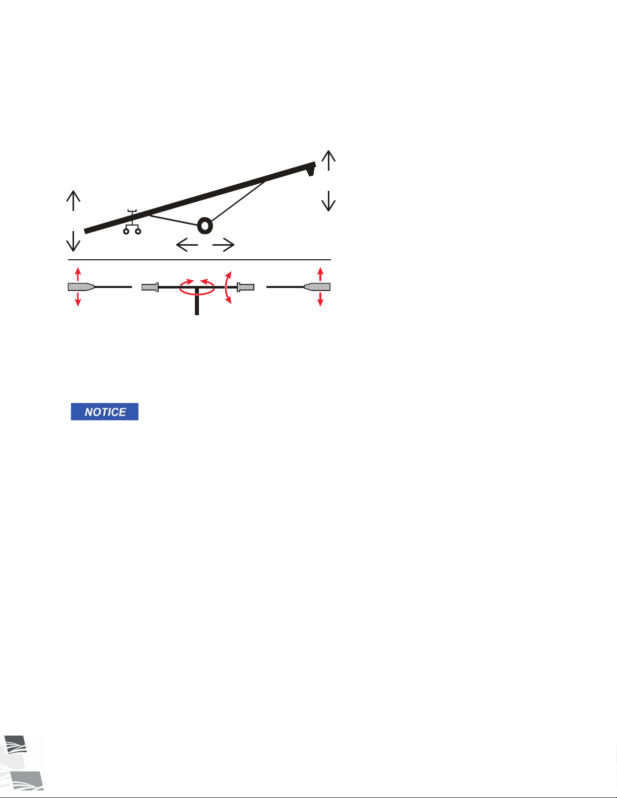
3. Refer to the controls shown in Figure 14.
4. Before moving the conveyor into position:
P1512137 R3 39
Page 40
1
4
3 2
4
2
3
1
5. PLACEMENT S-DRIVE STANDARD CONVEYOR – PORTABLE GRAIN BELT CONVEYOR
• Fully lower the conveyor.
• Raise the intake end slightly off the ground to position the conveyor.
• Raise the conveyor discharge end only for final positioning such as when next to a storage bin or grain
truck.
Figure 14. Wheel Move Kit Controls
If Operating the Wheel Move Kit in Temperatures Below -10°C (14°F):
• Disengage the pump when starting the motor cold. This will put less pressure on the starter and allow the
motor to turn over easier, helping it to start.
• Allow the hydraulic oil to warm before using the self-propelled kit.
Failure to warm the hydraulic oil can damage the pump or other components.
When Operation of the Wheel Move Kit is Complete:
1. Secure the wheel move kit axle to the conveyor when operation is complete or before transporting.
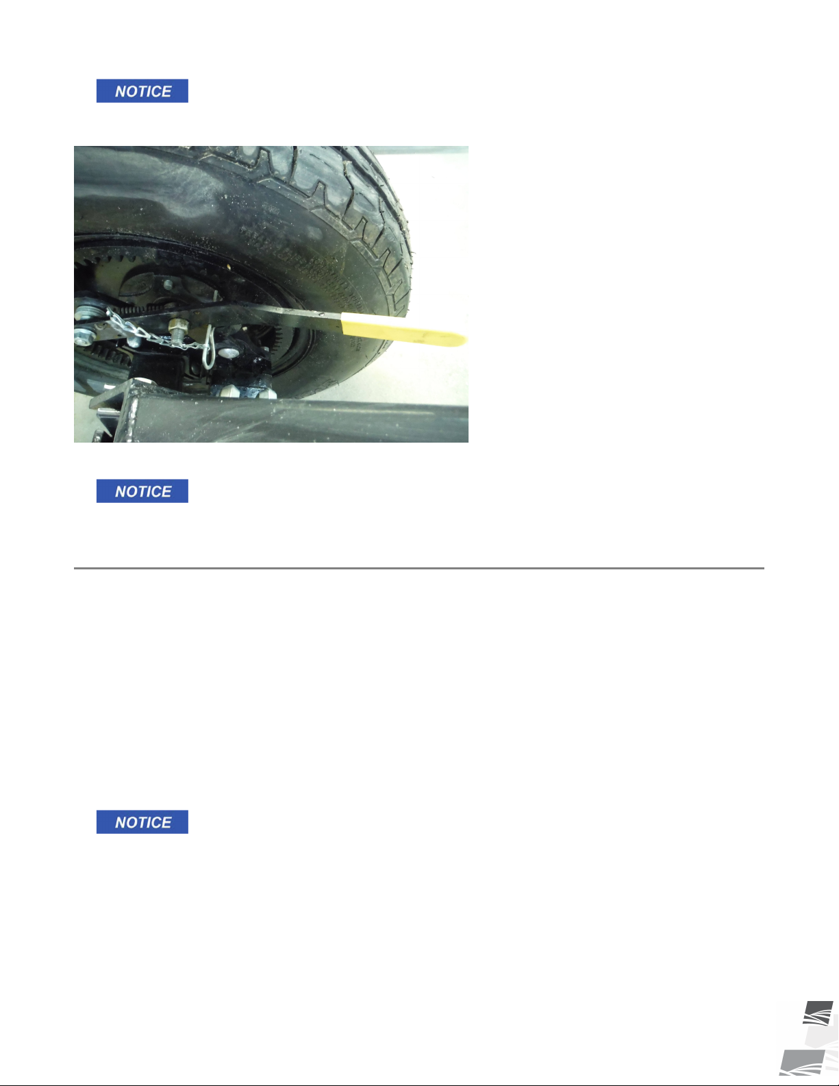
2. Fully disengage the over-center handles and secure the handle with the attached pin, see Figure 15 on page
41.
40 P1512137 R3
Page 41
Æ
S-DRIVE STANDARD CONVEYOR – PORTABLE GRAIN BELT CONVEYOR 5. PLACEMENT
Do not transport with the over-center handles engaged or damage to the wheel move kit
motors will occur.
Figure 15. Chain Position
3. Disengage the pump to take the strain off the conveyor drive components.
Ensure that the over-center bolts are tight enough to prevent the handle from engaging. If
they are not tight enough, damage to the gears and motor will result.
5.5. Raising and Lowering
When equipped with a Hydraulic Lift Cylinder:
The intake hopper must be off the ground when raising and lowering the conveyor.
Before using the hydraulic lift cylinder:
• The hydraulic cylinders are shipped without oil and must be charged with oil before operating the first time.
See the Appendix section for charging instructions.
• Check that the hydraulic hoses are free from leaks, binding, flattening, kinks, or wear.
Raising
1. Before connecting the hydraulic hose, wipe the hose coupler clean.
Dirt in the hydraulic system can damage the cylinder o-rings and can cause leakage and
failure of the system.
2. Connect the hydraulic hoses, ensure the connections are tight. Visually check for leaks, binding, flattening,
kinks, or wear.
3. Open the ball valve on the hose connected to the cylinder.
4. Start tractor and idle at low rpm.
5. Engage hydraulic lever to power the cylinder.
6. Increase tractor rpm until desired rate of lift is reached.
P1512137 R3 41
Page 42
5. PLACEMENT S-DRIVE STANDARD CONVEYOR – PORTABLE GRAIN BELT CONVEYOR
7. Raise the conveyor to the desired height.
8. Close the hydraulic ball valve when the conveyor is fully raised.
Failure to close the ball valve will cause the frame to lower, damaging the conveyor.
Lowering:
1. Reconnect the hydraulic hose coupler to tractor, if disconnected. Keep the tractor running while lowering
the conveyor should the need arise to re-lift it.
Some conveyors are equipped with dual acting hydraulic cylinders, for these units the
tractor must be running to pump oil oil to the upper chamber of the hydraulic cylinder(s)
to prevent overfilling of the tractor reservoir.
2. Open the ball valve.
3. Open the tractor valve, feathering the control to prevent too rapid a descent.
Note
Once the valves are opened, the conveyor tube lowers by gravity. As the tube nears the full down
position, the rate of descent will increase. Do not operate with the tractor valve fully open.
4. Turn off the tractor, and lock out the tractor power source.
5. Before disconnecting hydraulic couplers, relieve the hydraulic pressure.
Disconnecting a hydraulic hose under pressure can result in serious injury.
6. Adjust the conveyor in the full down position until there is a slight tension on the lift cable. Do not leave the
cable slack.
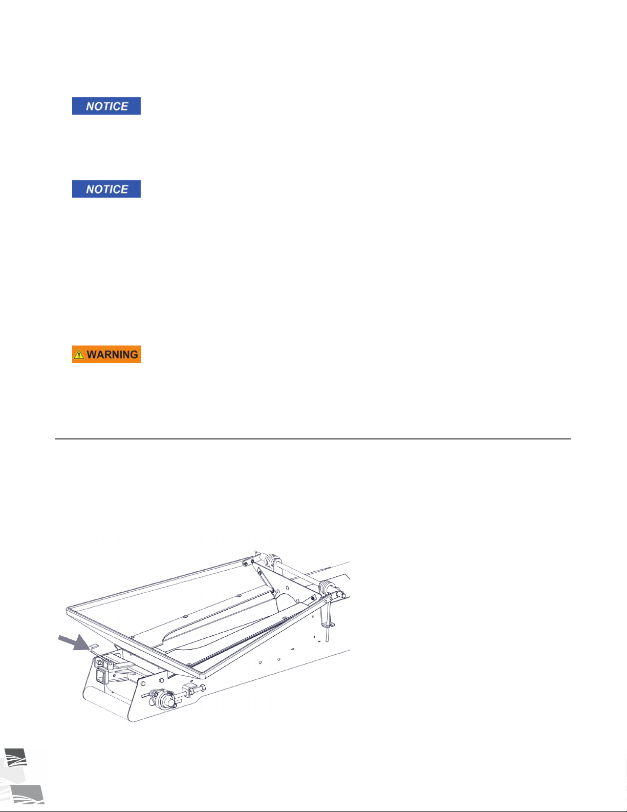
5.6. Collapsible Hopper Cloth
The conveyor is designed with a collapsible hopper cloth to allow it to go under low discharge units.
Push the hopper down and secure with hook. Push down again to release the hook and raise the hopper cloth.
Refer to Figure 16 on page 42.
Figure 16. Typical Collapsible Hopper
42 P1512137 R3
Page 43
S-DRIVE STANDARD CONVEYOR – PORTABLE GRAIN BELT CONVEYOR 5. PLACEMENT
5.7. Conveyor Operating Angles
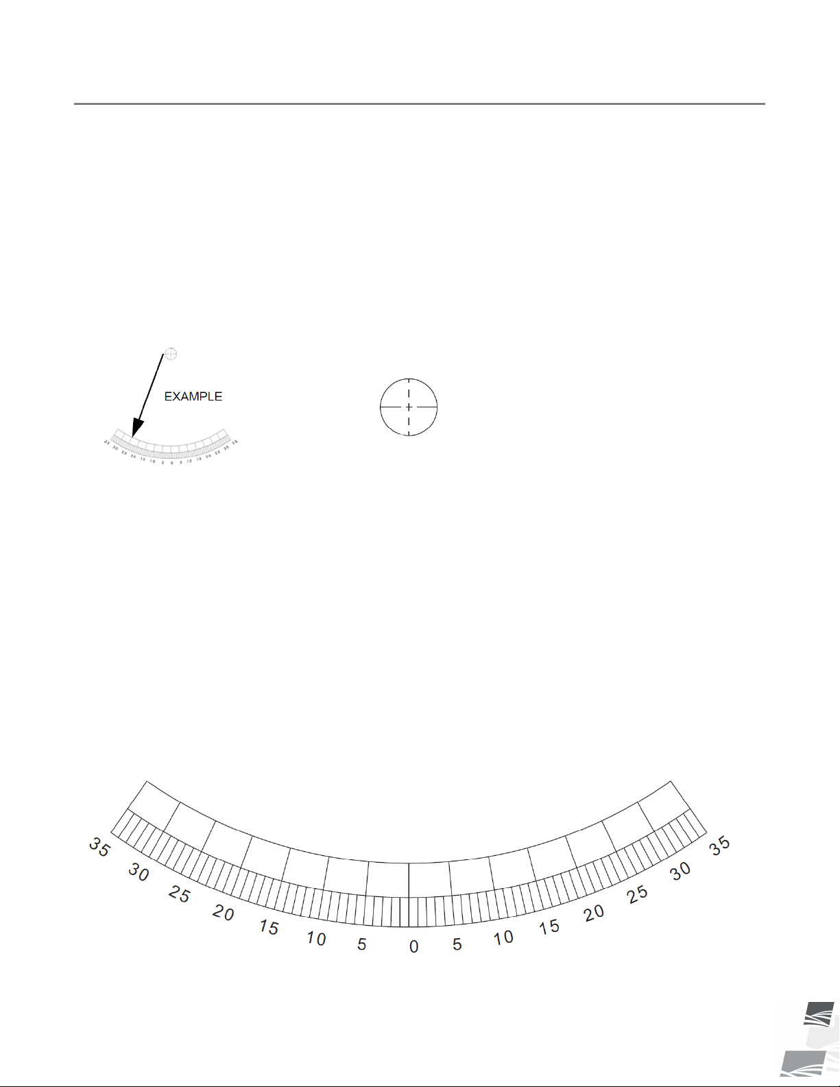
The conveyor lift can set the tube angle up to 30° when operating. Because the belt does not have roll back
barriers, the material will roll back if the angle is too steep. Do not position the conveyor at an angle steeper
than the grain will roll back (angle of repose) of the material to be moved.
Note
The lower the angle, the greater the capacity of the conveyor.
The following table indicates the maximum angle a conveyor can move grain.
To roughly determine conveyor angle, use angle guide on right. Stand the manual (vertically) on conveyor tube
and hold a string with a weight attached to end against the top of this page. Weighted end of string will fall
between degree lines, and from this the approximate angle of the conveyor can be determined.
Figure 17. Conveyor Operating Angles
P1512137 R3 43
Page 44

5. PLACEMENT S-DRIVE STANDARD CONVEYOR – PORTABLE GRAIN BELT CONVEYOR
Table 4. Maximum Conveying Angles for Grains
Grain
Flax
Lentils
Mustard
Maximum Conveyor Operating Angle (degrees)
24
29
26
Oats 28
Peas 30
Rice 36
Rye 25
Soybeans
Sunflower
Triticale
Wheat
28
22
23
26
Alfalfa Pellets
Barley
Canary Seed
Chickpeas
34
25
26
30
Corn 23
Shelled Corn (dry)
Shelled Corn (wet)
Cotton Seed
23
28
30-45
Durum 23
44 P1512137 R3
Page 45

Æ
S-DRIVE STANDARD CONVEYOR – PORTABLE GRAIN BELT CONVEYOR 6. OPERATION
6. Operation
Before continuing, ensure you have completely read and understood this manual’s
Safety section, in addition to the safety information in the section(s) below.
6.1. Operation Safety
• Keep away from rotating and moving parts, including the conveyor belt, drive components,
shafts, and bearings.
• Do not enter the grain bin while the conveyor is operating.
• Always operate with guards, covers, and shields in place.
• Have another trained person nearby who can shut down the equipment in case of accident.
• Keep the work area clear of bystanders.
• Keep the work area clean and free of debris.
• Ensure maintenance has been performed and is up to date.
Refer to your bin operation manual for specific operating and safety information for your bin.
6.2. Start-up and Break-in
Although there are no operational restrictions on the conveyor when used for the first time, it is recommended
that the following items be checked during the first hours of operation.
1. Check that the conveyor intake and discharge areas are free of obstructions.
2. Check conveyor belt alignment to ensure preset alignment does not vary under loaded conditions. See
Maintenance Section for alignment instructions.
3. Check the conveyor belt tension. See Maintenance Section for tension instructions.
4. Gas and Electric Drive Models: Check the drive belt tension and alignment. See Maintenance Section for
instructions.
5. Check the pinch roller bearings on the s-drive pinch roller are not tight.
6. Visually inspect the conveyor, see Visual Inspection in Maintenance Section.
7. Check tightness of all bolts/nuts, fasteners, and hardware (re-torque if necessary).
8. Start the conveyor and operate normally, refer to power source instructions for further detail.
9. Be aware of unusual sounds. If any are heard, determine the source and stop the conveyor. Lock out and
correct the problem before resuming work. If you are unsure of the problem or procedure, contact your
local dealer.
10. Do not run the conveyor for long periods of time without material on the conveyor belt because it increases
wear. Try to run only when moving material.
11. Stop the conveyor when it is empty of grain and lockout power, lower fully.
P1512137 R3 45
Page 46

Æ
Æ
6. OPERATION S-DRIVE STANDARD CONVEYOR – PORTABLE GRAIN BELT CONVEYOR
Important
After the initial start-up and inspection, the conveyor should be shut down and visually inspected
(see Maintenance Section) after approximately ten hours of operation.
6.3. Operation - Electric Motor Models
When equipped with an Electric Motor:
1. Turn the electric motor on.
2. Run until the conveyor is empty.
3. Turn off motor and lock out power source.
4. Unplug the power cord, wrap around the equipment and secure to prevent dragging, especially when
transporting or placing the conveyor.
6.4. Operation - Gas Engine Models
When Equipped with a Gas Engine:
1. If the drive belts are tight, disengage the belts.
2. Start the gas engine. Follow instructions provided with the gas engine for specific starting instructions.
3. Engage belt drive lever (when equipped).
Note
The drive belt should be just tight enough to not slip on the drive pulley. If the belt is too loose, it
will slip, lowering power transfer from the engine and possibly causing a squealing sound. If the belt
is too tight, it will cause excess wear.
4.
Note
The drive belt should be just tight enough to not slip on the drive pulley. If the belt is too loose, it
will slip, lowering power transfer from the engine and possibly causing a squealing sound. If the belt
is too tight, it will cause excess wear.
5. Adjust gas engine to provide maximum engine RPM.
6. Run until all grain has been emptied from the equipment.
7. Reduce engine speed to low idle.
8. Shut off engine and lock out power source.
9. Shut off fuel supply.
6.5. Operation - PTO Drive
1. Attach the PTO driveline securely to the tractor and confirm the connection to the conveyor shaft is secure.
2. Confirm the PTO driveline rotating shield and other shields/guards are in place and in good working order.
46 P1512137 R3
Page 47

S-DRIVE STANDARD CONVEYOR – PORTABLE GRAIN BELT CONVEYOR 6. OPERATION
3. Align the tractor axis with the conveyor input shaft to minimize the angles of the universal joints on the PTO
driveline.
Important
Check that the PTO does not exceed the maximum operating angle, refer to Section 9. –
Specifications on page 71.
4. Ensure the PTO drive on the tractor is in the off position before starting the tractor.
5. Start tractor engine at low idle, slowly engage the PTO with the tractor idling to prevent unneeded stress on
the drive components and shear bolts.
6. If everything is operating normally, start running grain through the conveyor and increase the tractor PTO to
the specified full speed to produce the required flow.
7. To shut down, reduce the speed to low idle and lock out the PTO.
8. Disconnect the PTO driveline from the tractor and secure it to the PTO transport saddle with the safety
chain and keep it in transport saddle when transporting.
When raising or lowering the conveyor:
Disconnect the PTO driveline.
When starting under load:
If restarting the conveyor under load (tube is full), engage the PTO with the tractor idling.
Engaging the PTO at high engine speed under load will result in equipment damage.
6.6. Loading Area
To achieve maximum capacity:
• Feed material onto the belt until the material tube clearance is 1/2”.
• Direct the flow of material into the input hopper in the direction of the belt travel for the best capacity.
Do not flood feed the hopper.
6.7. Conveyor Belt Speed
The best results are obtained when the input drives are set to provide a conveyor belt speed of 500 to 600 ft/
min on the 1500 series, and 600 to 650 ft/min on the 1800, 2000, and 2400 Series.
Count the number of belt revolutions per minute to determine belt speed. See Specifications for belt length.
Note
Use the connector splice as a reference when counting belt revolutions.
To calculate, for example, 600ft/minute belt speed for a 47ft belt:
Therefore, 12.76 or approximately 13 belt passes per minute will provide a 600ft/min belt speed.
Contact your dealer or the factory for the appropriate drive components to give the recommended belt speed.
P1512137 R3 47
Page 48

Æ
Æ
6. OPERATION S-DRIVE STANDARD CONVEYOR – PORTABLE GRAIN BELT CONVEYOR
If the belt speed is too low, conveyor may leak around transition area.
6.8. Emergency Shutdown
In an emergency situation:
1. Stop or shut down the power source immediately and lock out all power.
2. Stop the flow of material (if applicable).
3. Ensure the machine components come to a stop before inspecting.
4. Correct the emergency situation before resuming work.
6.9. Restarting with a Full Tube
When the conveyor is shut down inadvertently or due to an emergency, the tube may still be filled with grain.
1. With the power source locked out, remove as much of the grain as possible from the tube and intake using
a shop vacuum or other tool. Do not use your hands.
Starting under load may result in damage to the conveyor.
2. If guards or covers have been opened or removed, close or replace them before restarting the unit.
3. Electric and Gas Drive Models: It may be necessary to tighten the drive belts slightly to handle the heavier
than normal loads.
4. Gas and PTO Drive Models: Since the start-up torque loads are so much higher than normal when the
conveyor belting is full, restart at low speed. Do not let the conveyor belt drive roller spin on the belt if
conveying belt does not start moving immediately. This will damage the drive roller and conveying belt.
5. Once the conveyor has been started, you may resume normal operation.
6.10. Shutdown
When operation has been completed:
1. Once the conveyor is clear of grain, lock out the power source.
2. Lower the conveyor fully.
3. Clean out any remaining grain from the conveyor with a vacuum or sweep out.
4. Clean the entire work area.
5. Remove anchors, supports, and chocks.
6.11. Clean Out
After using your conveyor, follow the clean out steps below to ensure longer belt life and trouble free
operation. Failure to clean out the conveyor can cause build up of product on the belt and roller shafts, causing
spillage, roller misalignment, and excess wear/damage to the belt.
48 P1512137 R3
Page 49

S-DRIVE STANDARD CONVEYOR – PORTABLE GRAIN BELT CONVEYOR 6. OPERATION
Failure to lock out power can cause severe injury.
1. Remove any product remaining in the hopper and spout with a vacuum or sweep out.
2. Remove debris from shafts, sheaves, and drive belts (as equipped).
3. Once the conveyor is empty of all product, check for damage on belt and lacing such as notches or cut outs.
Any damage on belt may result in product getting under it creating a build-up. If belt replacement and relacing is necessary, refer to the Maintenance Section.
Important
Ensure the conveyor is free from all product and debris to prevent build-up. Any build-up on belt
and shaft becomes a source of spillage and can cause belt misalignment with the possibility of belt
edges sustaining damage on the fixed structure. Build-up on the hopper and spout will cause the
belt to wear faster due to drag.
4. Once cleaned out, cover intake to prevent moisture from collecting in hopper.
6.12. Conveying Fertilizer
Fertilizer may be conveyed using the conveyor when strictly operated at a reduced capacity and additional care
is taken to thoroughly clean the conveyor after operation.
Important
Fertilizer weakens the belt lacing and warranty is void on all lacing used with fertilizer. The belt lacing
may need to be replaced more often if you convey fertilizer.
Additional Operating Requirements
To prevent problems that can be caused by conveying fertilizer:
1. Do not allow fertilizer to fill over the edge of the belt. This will allow fertilizer to get under the belt and start
building up.
2. Reduce the flow if the conveyor belt starts to slip. Denser fertilizers will slow the conveyor belt down due to
the weight of the product. Too much material will cause the drive roller to slip and lead to additional wear
on the roller.
3. Do not move fertilizer with your conveyor in humid, wet or rainy conditions. This will cause buildup of
fertilizer under your conveyor belt.
Additional Clean-Out Procedures
Proper cleaning will help to ensure longer belt life and prevent excess rust formation.
1. Run conveyor empty at full speed for 5-10 minutes after conveying fertilizer. This will help ensure that any
product that may be under the belt will be cleaned out and prevent build up.
Do not attempt to manually remove build-up while conveyor is running.
2. Next, run the belt at low idle and inspect for damage on the belt and lacing, such as notches or cut outs
caused by mice and normal wear. Any damage on the belt may result in fertilizer getting under the belt
creating a buildup. Consider replacing the conveyor belt if it is in poor condition. If equipped with an electric
motor, inspect on the belt return side with the electric motor not running. Turn on the conveyor to expose
the belt that was previously in the tube. Turn off the conveyor and inspect the belt on the belt return, along
with the lacing.
P1512137 R3 49
Page 50
6. OPERATION S-DRIVE STANDARD CONVEYOR – PORTABLE GRAIN BELT CONVEYOR
3. Shutdown and lockout power to the conveyor and vacuum or sweep out any remaining fertilizer from the
hopper.
4. Remove the s-drive bottom cover and remove any buildup from this area and clean cover. Replace the cover
when complete.
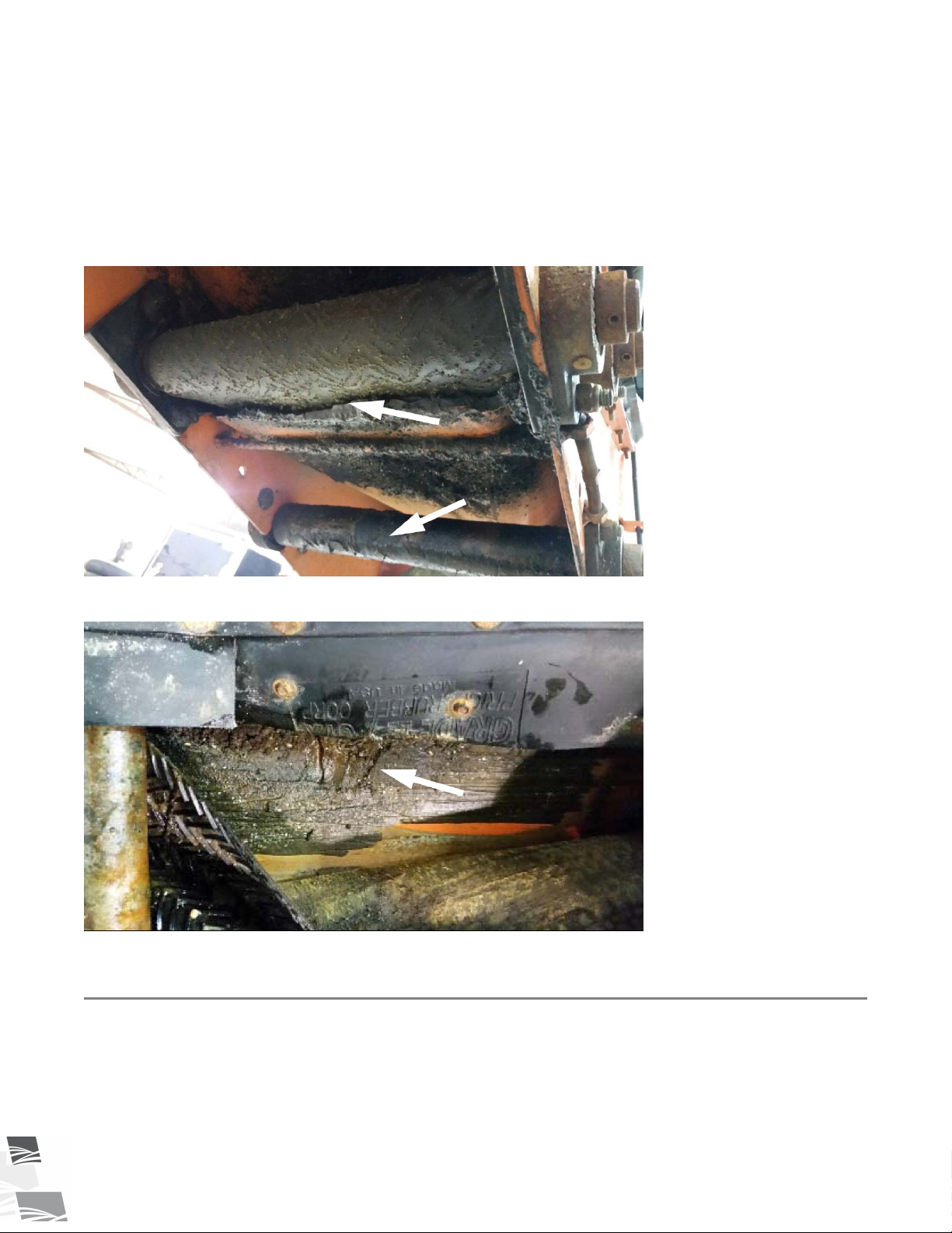
5. If buildup is evident on or under the belt, remove the buildup to ensure proper operation of the conveyor.
When necessary remove fertilizer buildup from under the belt by scraping and washing the belt.
Figure 18. Fertilizer Buildup on Rollers
Figure 19. Fertilizer Buildup at Hopper Transition
6.13. Storage
After the season’s use, the conveyor should be thoroughly inspected and prepared for storage. Repair or replace
any worn or damaged components and perform maintenance as described in the Maintenance Section to
prevent any unnecessary downtime at the start of the next season.
To ensure a long, trouble-free life, this procedure should be followed when preparing the unit for storage.
50 P1512137 R3
Page 51

Æ
S-DRIVE STANDARD CONVEYOR – PORTABLE GRAIN BELT CONVEYOR 6. OPERATION
1. Remove all residual material from the hopper and the tube.
2. Stop the machine with the belt lacing inside the tube. This helps prevent the lacing from rusting.
3. Wash the entire conveyor thoroughly using a water hose or pressure washer to remove all dirt, mud, debris,
or residue.
4. Inspect all moving or rotating parts to see if anything has become entangled in them. Remove any entangled
material.
5. Touch up all paint nicks and scratches to prevent rusting.
6. Check tire pressure and inflate. For inflation pressure, refer to Section 9. – Specifications on page 71.
7. Inspect the conveyor for cracks, tightness of fittings and fasteners, hydraulic hose cracks (if applicable). Have
required repairs performed to replace worn or damaged components.
8. Store in an area that is dry, level, free of debris, and away from human activity. Store inside if possible.
9. Cover the motor with waterproof tarpaulin if stored outside to protect from weather.
10. Chock wheels.
11. Support intake on blocks to eliminate prolonged contact with the ground.
12. PTO Models: Clean and lightly lubricate the spline on the PTO driveline. Cover the PTO driveline with a
plastic bag to protect it from the weather and place it in the transport saddle.
13. Lower the conveyor fully for storage.
P1512137 R3 51
Page 52
7. MAINTENANCE S-DRIVE STANDARD CONVEYOR – PORTABLE GRAIN BELT CONVEYOR
7. Maintenance
Before continuing, ensure you have completely read and understood this manual’s
Safety section, in addition to the safety information in the section(s) below.
7.1. Maintenance Safety
• Keep components in good condition. Follow the maintenance
procedures.
• Ensure the service area is clean, dry, and has sufficient
lighting.
• Do not modify any components without written authorization
from the manufacturer. Modification can be dangerous and
result in serious injuries.
• Shut down and lock out power before maintaining
equipment.
• After maintenance is complete, replace all guards, service
doors, and/or covers.
• Use only genuine Westfield replacement parts or equivalent.
Use of unauthorized parts will void warranty. If in doubt,
contact Westfield or your local dealer.
Before attempting maintenance of any kind:
• Lower the conveyor fully.
• Chock wheels.
• Support tube if performing maintenance on the
undercarriage assembly.
• If equipped with hydraulics: Before applying pressure to a
hydraulic system, make sure all components are tight and
that hoses and couplings are in good condition.
7.2. Maintenance Schedule
Proper maintenance habits mean a longer life, better efficiency, and safer operation. Please follow the
Maintenance Schedule below. Keep good records of the hours the conveyor has been operated and the
maintenance performed.
Daily:
Section 7.3. – Visually Inspect the Equipment on page 53
Section 7.4. – Lubricate the Equipment on page 54
Monthly:
When equipped: Section 7.7. – Inspect Hydraulic Hoses and Fittings on page 55
52 P1512137 R3
Page 53

Æ
S-DRIVE STANDARD CONVEYOR – PORTABLE GRAIN BELT CONVEYOR 7. MAINTENANCE
Section 7.8. – Inspect the Hopper Flashing on page 55
Section 7.9. – Check the Roller Bearings on page 55
Section 7.10. – Check the Roller Lagging on page 56
7.13. Inspect Belt Lacing on page 60
When equipped: Section 7.5. – Check the Gearbox Oil on page 54
Annually:
Section 7.11. – Tension the Conveyor Belt on page 56
Section 7.12. – Align the Conveyor Belt on page 58
Section 7.16. – Clean and Wash the Equipment on page 62
2–3 Years:
7.14. Replace the Belt Lacing on page 60
When equipped: Section 7.6. – Change the Gearbox Oil on page 55
As Required:
When equipped:Section 7.17. – Tension the Drive Belts on page 62
When equipped: Section 7.18. – Align the Drive Belts on page 63
When equipped: Section 7.19. – Replace the Drive Belts on page 63
Section 7.20. – Repack the Wheel Bearings with Grease on page 63
When equipped: Section 7.21. – Check/Adjust the Truss Cables on page 64
7.15. Replace the Conveyor Belt on page 60
Section 7.22. – Pinion Gear Adjustment on page 66
7.3. Visually Inspect the Equipment
Check the following during a visual inspection:
1. Ensure all guards are in place and in good working order.
2. Examine the conveyor for damage or unusual wear.
3. Check tightness of bolts/nuts, fasteners, and hardware (re-torque if necessary).
4. Be sure all safety decals are in place and are legible.
5. Check that the discharge and intake area are free of obstructions.
6. Inspect all moving or rotating parts to see if anything has become entangled in them. Remove any entangled
material.
Lock out power before inspecting.
7. When equipped: Inspect hydraulic hoses and fittings for leaks and wear. Fix or replace where necessary.
8. Check wheel bolts are tight and examine tires for gashes, uneven wear, or loss of air pressure. See Section 9.
– Specifications on page 71 for recommended tire pressure.
P1512137 R3 53
Page 54
Æ
Æ
7. MAINTENANCE S-DRIVE STANDARD CONVEYOR – PORTABLE GRAIN BELT CONVEYOR
9. Check all operating, lifting, and transport components. Replace damaged or worn parts before using the
conveyor.
10. PTO Models: Check the PTO shield & replace if damaged.
11. If equipped with truss cables: Inspect the truss cables for proper tension and possible damage such as
fraying, kinking, or unwinding.
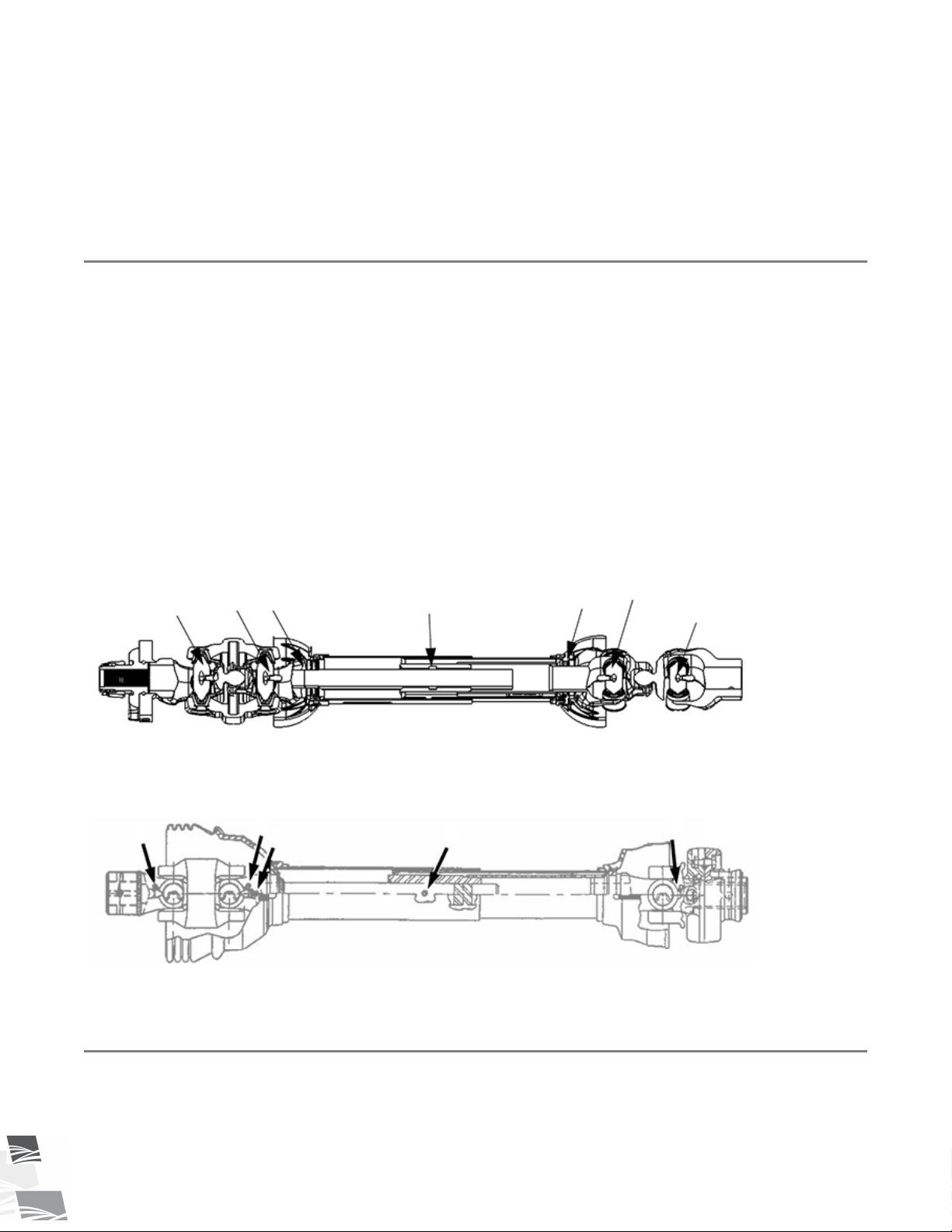
7.4. Lubricate the Equipment
Your equipment can operate at top efficiency only if clean fluids and lubricants are used. Use clean containers
to handle all fluids and lubricants. Store them in an area protected from dust, moisture, and other
contaminants.
1. Wipe the grease fittings with a clean cloth before greasing to avoid injecting dirt and grit.
2. Use a hand-held grease gun for all greasing.
3. If fittings will not take grease, remove and clean thoroughly.
4. Replace fittings if they are broken or will not accept grease.
Use SAE multi-purpose high-temperature grease with extreme pressure (EP) performance. SAE multi-purpose
lithium-based grease is also acceptable.
7.4.1 PTO Driveline
Figure 20. Typical PTO Driveline Grease Points
Figure 21. Typical PTO Driveline Grease Points
7.5. Check the Gearbox Oil
1. Remove fill/vent plug to check gearbox oil level. Insert an improvised dipstick (rolled paper or plastic tie)
into the oil filler hole to determine the oil level.
54 P1512137 R3
Page 55

Æ
S-DRIVE STANDARD CONVEYOR – PORTABLE GRAIN BELT CONVEYOR 7. MAINTENANCE
2. Note the level and the condition of the oil. Maintain oil level at half full (center of cross shaft) with 90W or
equivalent gear oil, adding as necessary or drain and refill if condition is poor.
3. Ensure gearbox is level when checking or refilling.
4. Do not overfill when adding oil.
5. Replace fill/vent plug.
7.6. Change the Gearbox Oil
Use SAE approved 90W or equivalent gear oil.
1. Remove gearbox from the conveyor.
2. Place a pan under the drain plug.
3. Use a wrench and remove the drain plug.
4. Loosen the filler plug so air can enter the gearbox and the oil will drain freely.
5. Allow the oil to drain completely.
6. Replace the drain plug.
7. Add oil until the gearbox is half full (center of cross shaft) and replace filler plug. A flexible funnel may be
required. Gearbox should be level when checking or refilling. Do not overfill.
8. Reinstall the gearbox and guards.
7.7. Inspect Hydraulic Hoses and Fittings
When equipped:
1. Pressurize the system.
2. Using a piece of cardboard or wood, run it along the length of the hose and around all fittings.
Escaping hydraulic fluid under pressure will cause serious injury if it penetrates the skin
surface.
3. Replace the hose or tighten/replace the fitting if a leak is found. For replacement hoses, refer to Section 9. –
Specifications on page 71.
4. Replace any hose that is badly cut, nicked, abraded, or is separating from the crimped end of the fitting.
5. Secure hoses to the machine.
7.8. Inspect the Hopper Flashing
Check hopper flashing for wear and replace any that are worn. Worn flashing will cause hopper leakage.
7.9. Check the Roller Bearings
Check the roller bearings for wear. Any rollers making noise, getting hot while running, or that give should be
replaced.
P1512137 R3 55
Page 56

7. MAINTENANCE S-DRIVE STANDARD CONVEYOR – PORTABLE GRAIN BELT CONVEYOR
7.10. Check the Roller Lagging
Inspect roller lagging to see if it is showing signs of wear.
Operating the conveyor with a damaged roller will result in a damaged conveyor belt.
7.11. Tension the Conveyor Belt
Adjusting your conveyor belt for proper tension helps to ensure trouble-free operation and long belt life.
The conveyor belt only needs to be tight enough to not slip on the drive roller. If the belt is too loose, it will slip
on the drive roller making a noticeable sound, slowing the belt down.
The conveyor belt should not be easy to pull from the hopper transition sides, otherwise the belt will require
tensioning.
Failure to stop using the conveyor with a slipping belt will damage it and/or the drive roller
lagging. In extreme cases, sections of burnt belt will have to be replaced. This type of damage
is not covered by warranty.
To set correct conveyor belt tension:
1. While the conveyor is running empty, fully tighten the nut against the pretensioner (take-up pipe) so that
the edge of the indicator pipe is within the green area, see Figure 22 on page 57.
2. Ensure the take-up roller is tensioned equally by using a tape measure to check the distance “X” on both
sides.
3. After the conveyor belt has been tensioned, check the alignment of all s-drive rollers, see Section 7.12. –
Align the Conveyor Belt on page 58.
4. If the belt is still loose after tensioning, the belt needs to be shortened or replaced (depending on wear).
56 P1512137 R3
Page 57
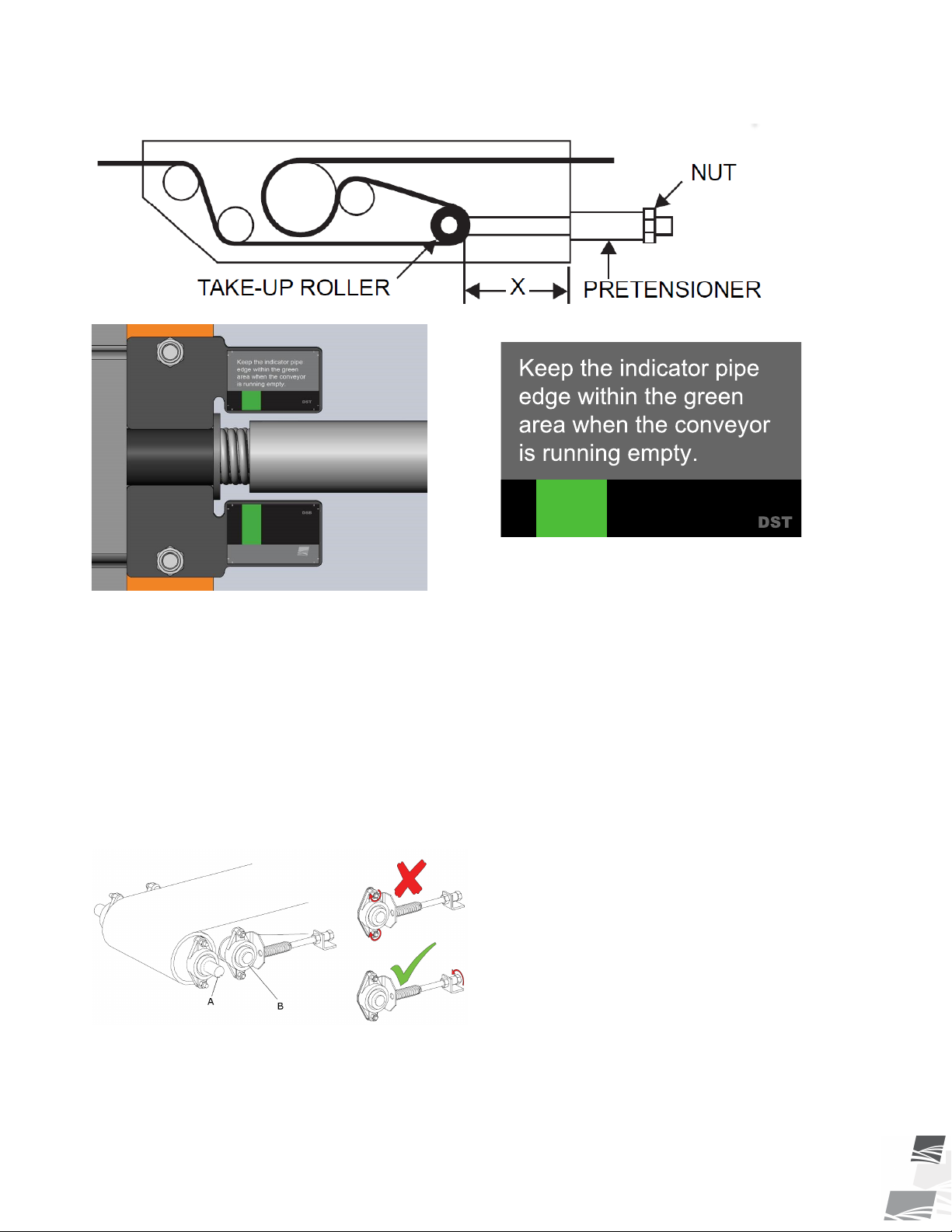
S-DRIVE STANDARD CONVEYOR – PORTABLE GRAIN BELT CONVEYOR 7. MAINTENANCE
Figure 22. S-Drive
7.11.1 S-Drive Pinch Roller
The s-drive pinch roller should always be set with its flange nuts wiggle loose, allowing the spring to push
against and pinch the conveyor belt. This should not normally require adjustment.
1. Do not tighten nuts. Bearing nuts must remain wiggle loose.
2. Tighten pinch spring, if loose.
3. Confirm that the pinch roller and drive roller are flush.
Figure 23. S-Drive Pinch Roller
A — Drive Roller
B — Pinch Roller
P1512137 R3 57
Page 58
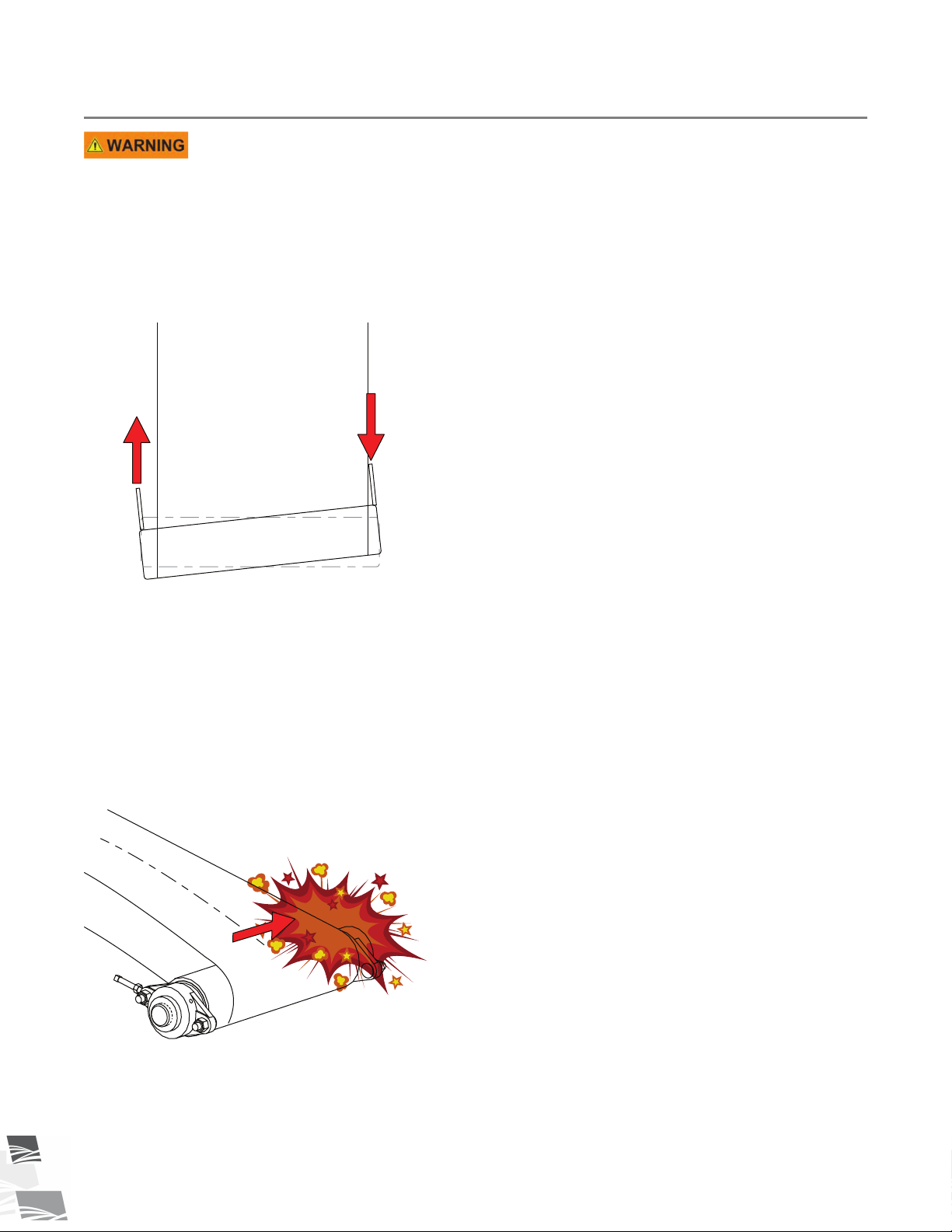
OR
LOOSEN TIGHTEN
7. MAINTENANCE S-DRIVE STANDARD CONVEYOR – PORTABLE GRAIN BELT CONVEYOR
7.12. Align the Conveyor Belt
Failure to lock out power can cause severe injury.
Basic Conveyor Belt Alignment:
The conveyor belt will run straight when all of the rollers are straight.
Loosen or tighten the adjustment bolt(s) to align the conveyor belt. Tighten the side the belt has moved toward,
or loosen the side the belt has moved away from.
Figure 24. Roller out of Alignment
Before Aligning the Belt:
• The conveyor must be empty of all grain.
• Wait until the belt makes a complete revolution before adjusting the rollers. Some belts may have uneven
edges, appearing misaligned.
To Align the Belt:
If your belt is tracking off-center, follow the sections and steps in the order following to center it.
Figure 25. Belt Tracking to One Side
58 P1512137 R3
Page 59
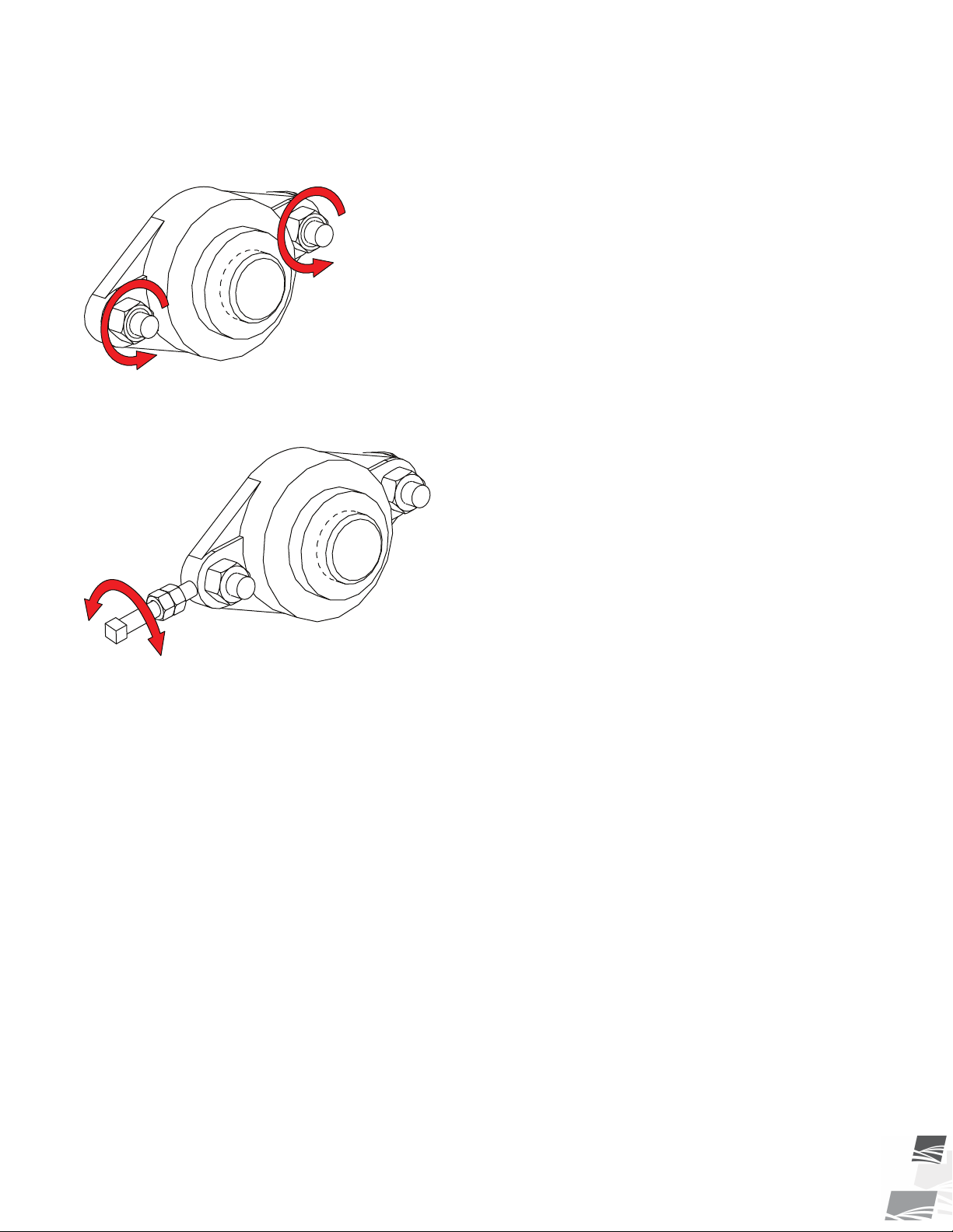
S-DRIVE STANDARD CONVEYOR – PORTABLE GRAIN BELT CONVEYOR 7. MAINTENANCE
7.12.1 Adjust the Rollers
1. Loosen bearing nuts and jam nuts (if equipped).
Figure 26. Loosen the Bearing Nuts
2. Rotate adjustment bolt 1/2 turn.
Figure 27. Rotate the Adjustment Bolt
3. Restart conveyor and run empty for 1 minute.
4. Stop the conveyor and remove ignition key or lock out the power source.
5. If the belt has centered, move to next step. If not, repeat Step 2 to Step 4 until the belt is centered.
6. Tighten the bearing bolts and jam nut (if equipped).
7. Replace any guards that were removed.
7.12.2 Adjust the Belt Return Wear Blocks
1. Adjust the wear blocks by rotating them 90 or 180 degrees. If they are worn down, replace the wear blocks.
P1512137 R3 59
Page 60
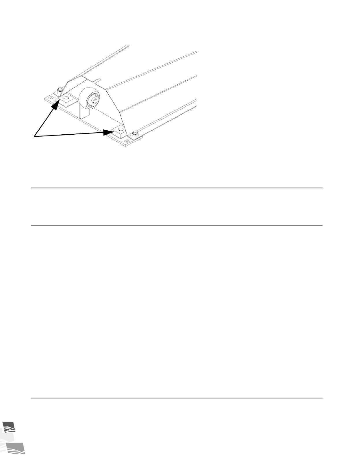
7. MAINTENANCE S-DRIVE STANDARD CONVEYOR – PORTABLE GRAIN BELT CONVEYOR
Figure 28. Belt Return Wear Blocks
2. Replace the guards if removed.
7.13. Inspect Belt Lacing
Inspect the condition of the belt lacing, if any clips are worn through, replace all lacing.
7.14. Replace the Belt Lacing
1. Rotate the conveyor belt until the lacing is by the hopper or is easily accessible.
2. Loosen the conveyor belt and remove the lacing retainer clip and pin.
3. Using a square and sharp knife, cut the lacing off right behind the lacing clips. The cut belt MUST have a
square end.
4. Use a knife to cut Chevron pattern off 1” back from the end of the belt. This ensures that the lacing is
centered and fully seated on the belt.
5. Use a lacing tool to install new lacing clips. Lacing clips are one clip shorter than the belt width. For example:
the lacing for a 15” wide belt is 14 clips. Center the lacing on the belt and install the lacing as per
instructions on the lacing tool.
6. Reattach the conveyor belt ends together. If required, use a ratchet strap clamped to both ends of the belt
to cinch the belting ends together. Figure 29 on page 61.
7. Install the lacing pin and crimp the retainer clips onto each end of the lacing pin. Figure 30 on page 62.
8. Remove the ratchet strap and tighten the conveyor belt (see “Conveyor Belt Tension”).
9. Check and set the belt alignment (see “Conveyor Belt Alignment”).
10. Engage the conveyor drive. Allow the conveyor to run for 30 seconds, then shut down the conveyor and
inspect the lacing.
7.15. Replace the Conveyor Belt
1. Rotate the conveyor belt until the lacing is by the hopper or is easily accessible.
60 P1512137 R3
Page 61
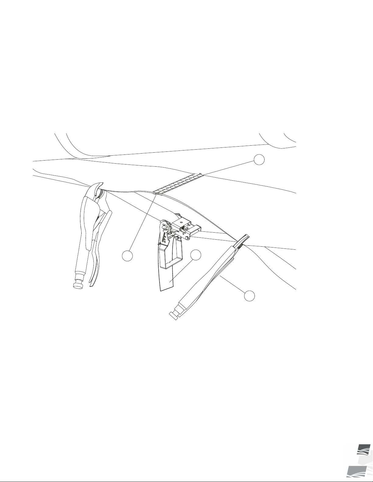
1
3
4
2
S-DRIVE STANDARD CONVEYOR – PORTABLE GRAIN BELT CONVEYOR 7. MAINTENANCE
2. Move the tension roller to its loosest position.
3. Pull all the slack to the lacing area.
4. Remove the lacing retainer clip and pin.
5. Attach one end of the replacement belt to the belt end being removed, closest to the hopper.
6. Pull the old belt out and the new belt will be threaded into place.
7. Disconnect the old belt.
8. Reattach conveyor belt ends together. If required, use a ratchet strap clamped to both ends of belt to cinch
belting ends together. Figure 29 on page 61.
Figure 29. Using the Ratchet Strap
9. Install the lacing pin and crimp the retainer clips onto each end of the lacing pin, see Figure 30.
10. Remove the ratchet strap and tighten the conveyor belt (see “Tension the Conveyor Belt”).
11. Check and set the belt alignment (see “Align the Conveyor Belt”).
12. Engage the conveyor drive. Allow it to run for 30 seconds, then shut down the conveyor and inspect the
lacing.
P1512137 R3 61
Page 62
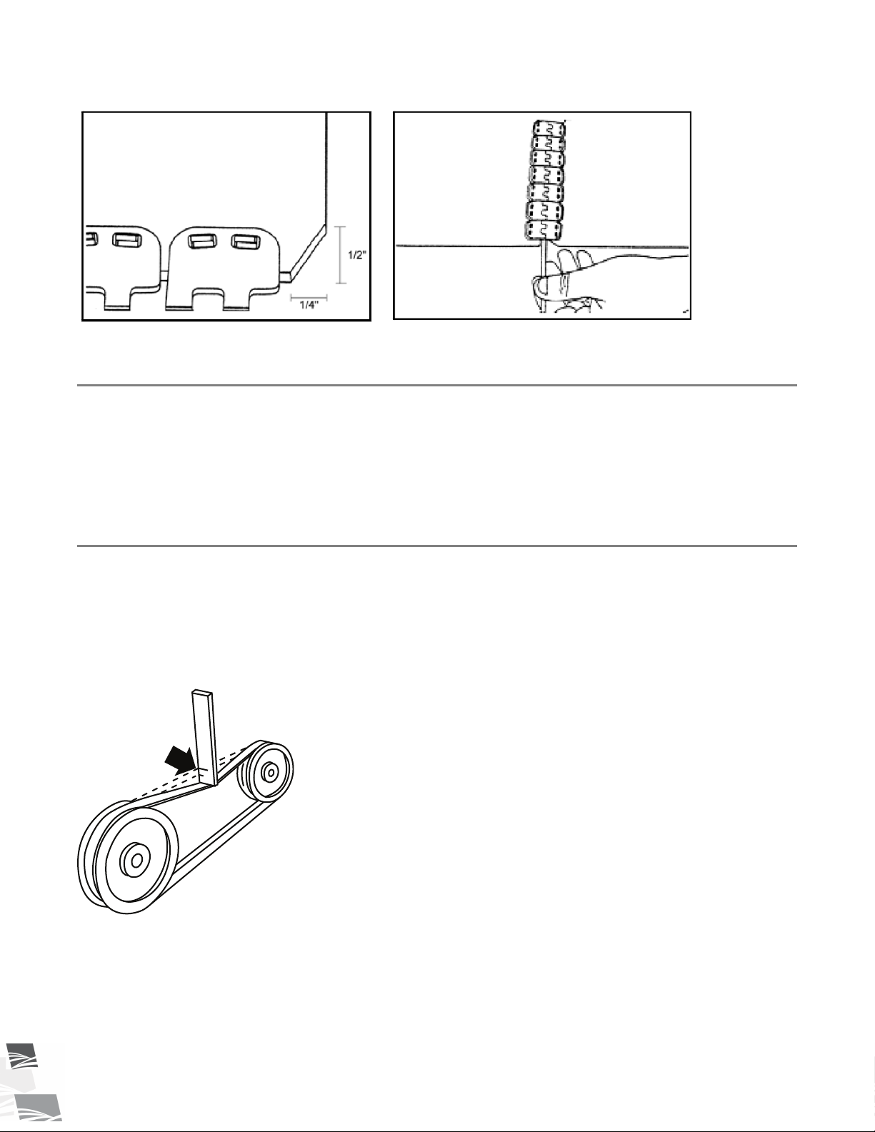
Æ
1 inch
(25 mm)
7. MAINTENANCE S-DRIVE STANDARD CONVEYOR – PORTABLE GRAIN BELT CONVEYOR
Figure 30. Lacing the Conveyor Belt
7.16. Clean and Wash the Equipment
1. Clean out excess grain from all areas of the conveyor.
2. Make sure water can drain from the conveyor tube and intake, then wash the tube with a water hose or
pressure washer until all dirt, mud, debris, or residue is gone.
3. Provide sufficient time for the water to drain from the conveyor.
7.17. Tension the Drive Belts
When equipped:
1. Remove guard and push on the center of the belt span with a force of approximately 5 lb.
2. The belts will deflect approximately 1” (25 mm) when properly tensioned.
Figure 31. Typical Drive Belt Tensioning
3. Tighten or loosen the drive belts (or idler pulley when equipped) to achieve the proper tension.
62 P1512137 R3
Important
The drive belt should be just tight enough to not slip on the drive pulley when operating. If the belt
is too loose, it will slip, possibly causing a squeaking sound and slowing the belt down. If the belt is
too tight, it will cause excess wear.
Page 63

Æ
Æ
S-DRIVE STANDARD CONVEYOR – PORTABLE GRAIN BELT CONVEYOR 7. MAINTENANCE
4. Reattach and secure guard. Start system to ensure proper operation.
7.18. Align the Drive Belts
When equipped:
1. Lay a straight edge across the pulley faces to check the alignment.
2. Use the pulley hub to move the pulley to the required position for alignment.
3. Tighten the hub bolts to secure pulley on the drive shaft.
4. Check the belt tension.
5. Reattach and secure the guard.
7.19. Replace the Drive Belts
When equipped:
1. Remove the guard.
2. Fully loosen the drive belts.
3. Remove and replace the old belts.
4. Tighten the drive belts as described in Belt Tension.
5. Align the drive belts as described in Belt Alignment.
6. Reattach and secure the guard.
7.20. Repack the Wheel Bearings with Grease
1. Block wheels and ensure unit is stable.
2. Remove the wheel bolts and the wheels.
3. Clean wheel and hub mounting surfaces to ensure there is no rust or debris.
4. Remove the wheel bearing and pack with grease. Use SAE multi-purpose high-temperature grease with
extreme pressure (EP) performance. SAE multi-purpose lithium-based grease is also acceptable.
5. Tighten the wheel bolts (diagonal pattern) with a torque wrench to 100 ft-lb (±10 ft-lb) of torque. Inspect to
make sure the wheel is sitting flush with the hub.
P1512137 R3 63
Page 64
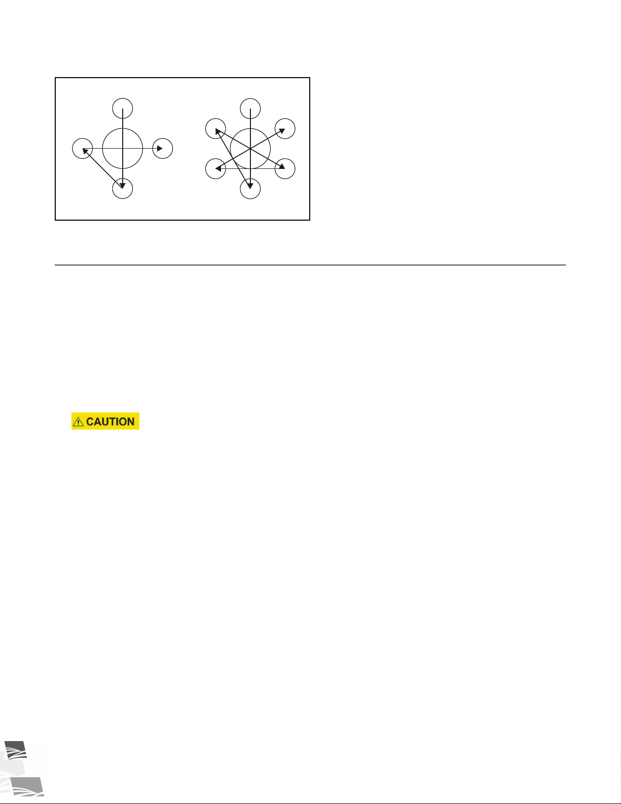
1
2
3 4
1
2
3 6
45
Æ
Æ
7. MAINTENANCE S-DRIVE STANDARD CONVEYOR – PORTABLE GRAIN BELT CONVEYOR
Figure 32. Diagonal Pattern for 4-bolt and 6-bolt Tires
7.21. Check/Adjust the Truss Cables
When equipped with Truss Cables:
Check the Truss Cables:
Check tube for straightness, no slack in the cables, and a just noticeable upward deflection of the discharge end.
During operation, it is normal that for the tube to deflect downward.
If required, adjust cables by following the procedure below:
1. Lift the discharge end of the conveyor with a overhead crane, front end loader, or other proper lifting device
so that the tube has a slight upward deflection at the discharge to give the cable some slack.
The lifting device must be capable of supporting approximately half of the weight of the
conveyor as provided in the Specifications section.
2. When the conveyor has more than one set of cables start from the innermost cables and work your way
out.
3. Loosen cable clamps on cable truss where the cable requires adjustment.
4. Locate the eyebolt anchors for the cable. Refer to Figure 33 on page 65.
5. Tighten cable eyebolts evenly on both sides (use eyebolt nuts to tighten eyebolts) until the discharge end
just starts to angle upward.
• The tube should not deflect to the left or right if tightened evenly.
• Tension should be greater on shorter cables than on longer cables. If the conveyor tubes remain straight
then the cables are tensioned properly.
6. If the proper cable tension can’t be obtained before the eyebolts run out of adjustment, then do the
following:
a. Loosen the eyebolts.
b. At the eyebolts, loosen the cable clamps, shorten the cables until there is tension on the cable, then
tighten the cable clamps fully.
c. Return to step 5.
7. Secure jam nut on cable eyebolt and re-tighten any cable clamps that were loosened.
8. The cables are properly tightened when:
64 P1512137 R3
Page 65
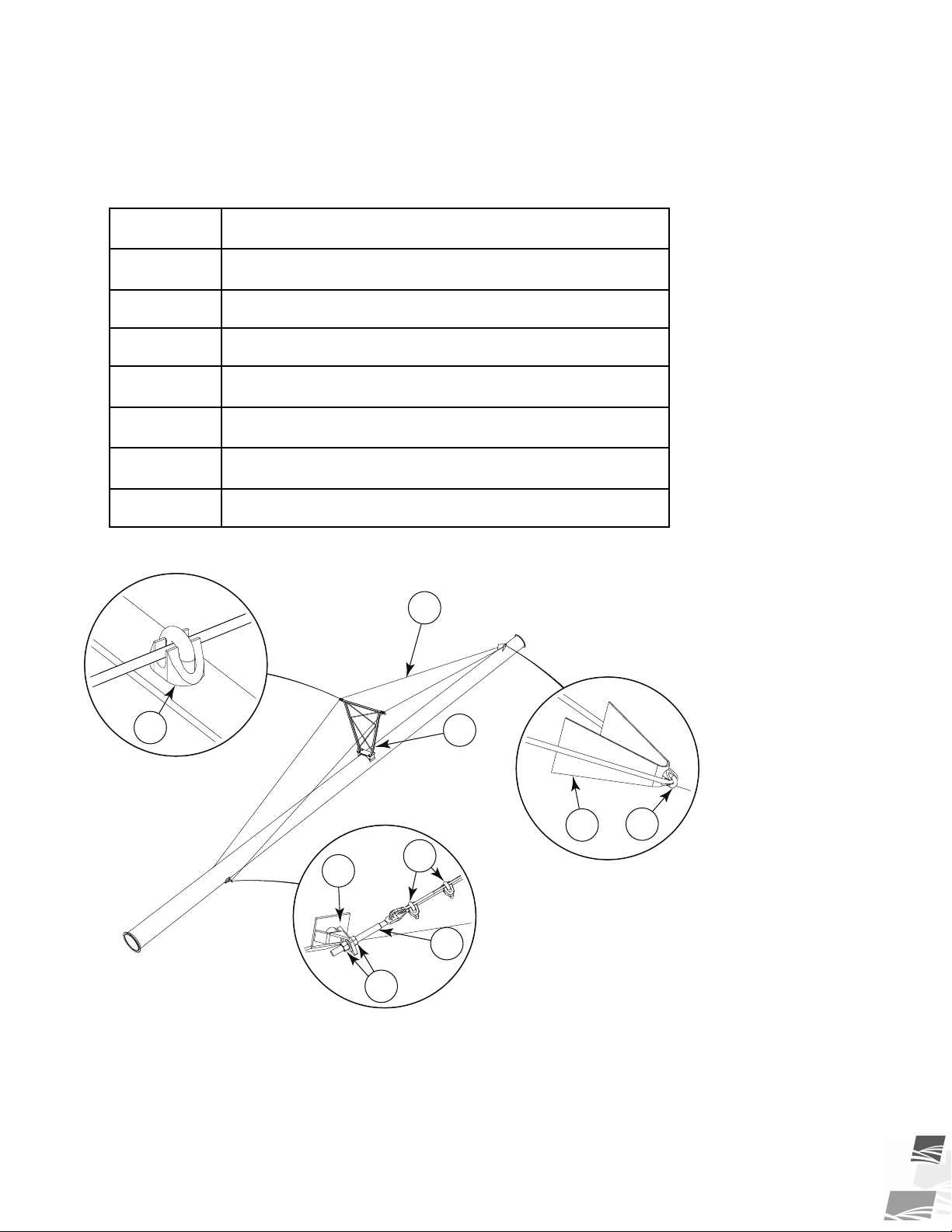
2
7
1
6
1
1
3
4
5
S-DRIVE STANDARD CONVEYOR – PORTABLE GRAIN BELT CONVEYOR 7. MAINTENANCE
• There is no slack in the cables.
• The discharge end is deflected sightly upwards.
• The tube is straight side-to-side.
Table 5. Truss Cable Adjustment
Item
1
2
3
4
5
6
7
Figure 33. Typical Cable Truss Assembly
Description
Cable Clamp
Truss Cable
Cable Return Bracket
Cable Eyebolt
Eyebolt Nuts
Eyebolt Anchor
Cable Truss
P1512137 R3 65
Page 66
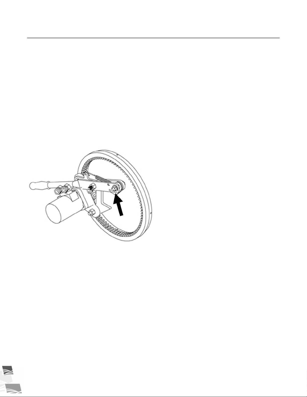
Æ
7. MAINTENANCE S-DRIVE STANDARD CONVEYOR – PORTABLE GRAIN BELT CONVEYOR
7.22. Pinion Gear Adjustment
When Equipped:
The pinion gear should mesh with the ring gear to provide maximum tooth contact. If the pinion gear does not
mesh entirely with the ring gear:
1. Adjust the handle slot bolt (which bolts to the drive mount clamp) so full meshing of the pinion gear is
achieved when the handle is in the over-center position. The pinion gear will need adjustment when gear
teeth bind or are not meshing sufficiently.
• Gear teeth binding: If the handle will not lock into over-center position, loosen the slot bolt nuts and
slide the handle away from the tire.
• Insufficient Meshing: If the pinion gear will barely mesh with the ring gear, loosen the slot bolt jam nuts
and slide the handle towards the tire until the pinion gear teeth mesh with the ring gear teeth without
binding.
Figure 34. Pinion Gear Adjustment Nut
66 P1512137 R3
Page 67

S-DRIVE STANDARD CONVEYOR – PORTABLE GRAIN BELT CONVEYOR 8. TROUBLESHOOTING
8. Troubleshooting
Shut down and lock out all power sources before diagnosing any of the causes or
attempting any of the solutions below.
In the following section, we have listed some causes and solutions to some of the problems you may
encounter.
If you encounter a problem that is difficult to solve, even after having read through this section, please
contact your local dealer or distributor. Before you contact them, please have this operation manual
and the serial number from your machine ready.
Conveyor
Problem
Low conveying
capacity.
Low capacity for some
grains.
Conveyor belt slipping. Conveying belt loose. Tighten and align belt, see Belt Tension
Cause
Conveyor angle is too high. Re-position with lower tube angle, see
Incorrect belt speed. Verify and adjust belt speed to
Conveyor belt slipping. Tighten conveyor belt, see Conveyor Belt
When Equipped:
Drive belts slipping.
Smaller and smoother grains
will slide at shallower angles.
Drive roller lagging worn or
damaged.
Solution
Operation.
appropriate speed, see Belt Speed in
Operation.
Tension in Maintenance.
Tighten belts, see Drive Belt Tension in
Maintenance.
Reduce conveyor height, see Conveyor
Operating Angles in Operation.
and Belt Alignment in Maintenance.
Replace drive roller lagging, see dealer.
When Equipped:
Drive belts loose.
Belt frozen to tube from
operating in high humidity in
cold conditions.
Excessive conveyor
belt edge fraying.
Conveyor belt loose. Belt stretches over time. Re-tension belt, see Belt Tension in
P1512137 R3 67
Belt not aligned. Align belt, see Belt Alignment in
Tighten belts, see Drive Belt Tension in
Maintenance.
Remove conveyor from area of high
humidity and warm belt to de-ice.
Maintenance.
Maintenance.
Page 68

8. TROUBLESHOOTING S-DRIVE STANDARD CONVEYOR – PORTABLE GRAIN BELT CONVEYOR
If belt is fully tensioned, you may need to
shorten belt and re-lace, see Belt Relacing
in Maintenance.
Grain leaking from
conveyor hopper.
Hopper cloth
collapsing under grain.
Grain leaking from
conveyor discharge
between belt and
tube.
Belt not aligned (centered).
Flashing installed incorrectly
or worn.
Hopper cloth worn or
damaged.
When equipped: Transition
filler rings are worn.
Misaligned or broken spring
(s).
Pivot shafts improperly
installed.
Belt not aligned (centered).
Align belt, see Belt Alignment in
Maintenance.
Inspect flashing for wear and replace if
required.
Replace damaged hopper cloth.
Replace transition filler rings.
Check spring installation and repair as
required.
On some machines, switching pivot shafts
left to right will increase hopper tension.
Align belt, see Belt Alignment in
Maintenance.
Grain leaking from
conveyor discharge
Belt speed is too fast, hood
plugging.
between hood and
belt.
U-clamps or brackets
sliding on tube.
U-clamps or brackets not
properly crimped to tube.
Drive
Problem
Drive making noise.
Cause
When Equipped:
Slipping drive belt.
Hot shaft, pulley or bearing. Overheated components indicate a failed
Broken drive roller. Replace damaged component.
Scissor Lift Hydraulics (when equipped)
Decrease belt speed, see Belt Speed in
Operation.
Contact dealer or Westfield to correct
positioning.
Solution
Tighten belts, see Drive Belt Tension in
Maintenance.
bearing that must be repaired.
68 P1512137 R3
Page 69

S-DRIVE STANDARD CONVEYOR – PORTABLE GRAIN BELT CONVEYOR 8. TROUBLESHOOTING
Problem
Valve is leaking.
Cause
Loose/cracked fittings. Tighten/replace fittings.
Worn hose. Replace hose.
Valve spools are worn. Replace valve.
Machine operates
Oil is hot. Check oil level and add if required.
slowly.
Blockage in hydraulic lines. Suction hose blocked or kinked.
Power source is not producing
enough oil volume and/or
pressure.
Hydraulic cylinder
Worn seal. Replace seal.
leaking.
Mover Kit with Scissor Lift Conveyor (when equipped)
Solution
Speed up the engine to produce more
flow/pressure The power unit may not
have enough capacity to operate properly.
Problem
Valve is leaking.
Machine operates
slowly.
Cause
Solution
Loose/cracked fittings. Tighten/replace fittings.
Worn hose. Replace hose.
Valve spools are worn. Replace valve.
Oil is hot.
Check oil level and add oil if required (use
general purpose ISO 32 hydraulic oil).
Blockage in hydraulic lines. Suction hose blocked or kinked.
Power source is not producing
enough oil volume and/or
pressure.
Speed up the engine to produce more
flow/pressure The power unit may not
have enough capacity to operate properly.
Cushion block needs adjusting. Adjust valve on cushion block by turning
inward 1/8 of a turn at a time, refer to
Ram and Travel Speed.
Filter plugged (if equipped). Change filter.
Hydraulic cylinder
Worn seal. Replace seal.
leaking.
P1512137 R3 69
Page 70

8. TROUBLESHOOTING S-DRIVE STANDARD CONVEYOR – PORTABLE GRAIN BELT CONVEYOR
Conveyor doesn’t
drive.
Pinion gear slipping or
binding.
Cushion block needs adjusting. Adjust needle valve by turning clockwise
1/8 of a turn - try and repeat if necessary,
refer to Ram and Travel Speed.
Pinion gear not adjusted
properly.
Adjust the pinion gear. See Pinion Gear
Adjustment.
70 P1512137 R3
Page 71
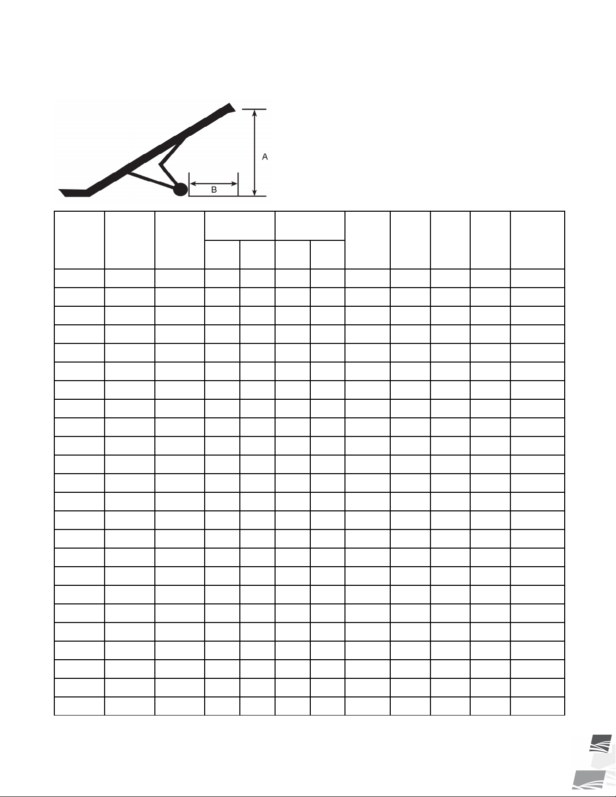
S-DRIVE STANDARD CONVEYOR – PORTABLE GRAIN BELT CONVEYOR 9. SPECIFICATIONS
9. Specifications
Model
1555
1565
1575
1585
1590
15100
1835
1845
1855
2035
2045
2055
2065
Belt
Length
115'3"
135'6
155'
175'
185'
205'
73'9"
93'9"
113'9"
77'10"
97'10"
117'10"
137'10"
Weight
(lbs)
2354 26.3 22.2 14.9 23.6 9 30 HP 10 HP 27 HP
2997 31.4 22.4 11.6 26.1 11 30 HP 15 HP 27 HP
3252 36.6 30.9 12.6 36.2 11 40 HP 20 HP 27 HP
3734 41.7 35.2 14.2 41.7 11.3 40 HP 20 HP 35 HP
3850 44.2 39.5 14.9 46.7 11.3 50 HP 25 HP 35 HP
4450 49 39.7 13.5 48.3 11.3 50 HP 25 HP 35 HP
2246 15.5 15.5 11 17.1 7.5 25 HP 10 HP
2532 21.1 18 12.5 22 7.5 30 HP 10 HP
3076 26.1 23 15.4 24.3 10.3 40 HP 15 HP
2765 16.1 16.9 10.7 17.4 7.5 40 HP 15 HP
3098 20.8 21.4 13 22.7 7.5 40 HP 15 HP
3650 26.1 24.7 13.8 24 10.3 50 HP 20 HP
4826 31.1 22.3 12.2 25.3
Up-Operation
A
(ft)
B
(ft)
Down -
Transport
A
(ft)
B
(ft)
Width
(ft)
*11.6
HP PT0 HP ELEC HP GAS
N/A N/A
N/A N/A
N/A N/A
N/A N/A
N/A N/A
N/A N/A
60 HP 25 HP
N/A N/A
HP HYD.
(Cu.in.)
N/A
N/A
N/A
N/A
N/A
N/A
2075
2085
2095
20105
20110
20120
2465
2475
2485
2495
24105
P1512137 R3 71
157'10"
177'10"
197'10"
217'10"
227'10"
247'10"
141'2"
161'2"
181'2"
201'2"
221'2"
5126 36.3 31.1 13.7 35.3
5868 40.7 32.1 12.7 38.1
6127 46.4 40.7 14.4 48
7990 51.1
8800 54
9430 58.6
5081 32.1 23.4 12.5 26
5396 36.1 32 14.3 35.8
6153 42.3 32.6 13.7 38.6
6630 47.1 41.5 14.9 48.5
8305 52.5
N/A
N/A
N/A
N/A
15.9
17.1
17.4
16.3
N/A
N/A
N/A
N/A
*11.6
*11.6
*11.6
**13.92
**13.92
**13.92
*11.6
*11.6
*11.6
*11.6
**13.92
60 HP 30 HP
70 HP 30 HP
80 HP 40 HP
80 HP 40 HP
90 HP 50 HP
100 HP 50 HP
60 HP 25 HP
70 HP 30 HP
80 HP 30 HP
80 HP 40 HP
90 HP 40 HP
N/A N/A
N/A N/A
N/A N/A
N/A N/A
N/A N/A
N/A N/A
N/A N/A
N/A N/A
N/A N/A
N/A N/A
N/A N/A
Page 72

9. SPECIFICATIONS S-DRIVE STANDARD CONVEYOR – PORTABLE GRAIN BELT CONVEYOR
Model
24110
24120
Belt
Length
231'2"
251'2"
Weight
* Extends out to 14.8’
** Extends out to 16.63’
Up-Operation
(lbs)
9495 53.9
9770 60
A
(ft)
B
(ft)
N/A
N/A
Down -
Transport
A
(ft)
17.1
18.4
B
(ft)
N/A
N/A
Width
(ft)
**13.92
**13.92
HP PT0 HP ELEC HP GAS
100 HP 50 HP
120 HP 50 HP
N/A N/A
N/A N/A
HP HYD.
(Cu.in.)
72 P1512137 R3
Page 73

S-DRIVE STANDARD CONVEYOR – PORTABLE GRAIN BELT CONVEYOR 10. AGI SWIFT CURRENT
LIMITED WARRANTY
10. AGI Swift Current Limited Warranty
This warranty relates to Belt Conveyors (the “Product”) sold by Batco-Rem, (a division of Ag Growth
International Inc., referred to herein as the “Seller”) and applies only to the first user of the Product
(meaning a purchaser directly from the Seller or from an authorized dealer or distributor of the
Product, referred to herein as the “Buyer”).
This warranty shall only be effective if properly registered with the Seller in accordance with
information provided to the Buyer at the time of sale.
1. The Seller warrants to the Buyer that the Product is free from defects in material and workmanship
under normal and reasonable use and in accordance with manufacturer’s manual.
2. This warranty applies only to defects in materials and workmanship and not to damage incurred in
shipping or handling, through normal wear and tear, or damage due to causes beyond the control
of the Seller such as lightning, fire, flood, wind, earthquake, excessive voltage, mechanical shock,
water damage, or damage arising out of abuse, alteration, improper assembly, improper
installation, improper maintenance or improper repair of the Product.
3. The warranty period for the Product shall be two years from delivery of the Product to the Buyer
where the Product is used in a normal farm operation. First year of warranty coverage of parts
and repair labour, second year warranty coverage of parts only. Warranty period for the Product
shall be 90 days from delivery of the Product to the Buyer where the Product is used in a
commercial operation. No warranty is given where the Product was used to convey canola. In
the event that any part incorporated into the Product is manufactured and sold to the Seller by a
third party vendor, such part is only warranted to the extent of the warranty given by that third
party.
4. This warranty does not obligate the Seller to bear costs of travel in replacing defective parts.
5. The obligations set forth in this warranty are conditional upon the Buyer promptly notifying the
Seller of any defect and completing reasonably required documentation and, if required, promptly
making the Product available for correction.
6. The total liability of the Seller on any claim, whether in contract, tort or otherwise, arising out of,
connected with, or resulting from the manufacture, sale, delivery, repair, replacement or use of the
Product or any part thereof shall not exceed the price paid for the Product and the Seller shall not
be liable for any special indirect, incidental or consequential damages caused by reason of the
installation, modification, use, repair, maintenance or mechanical failure of the Product.
Consequential or special damages as used herein include, but are not limited to, lost or damaged
products or goods, costs of transportation, lost sales, lost orders, lost income, increased
overhead, labor and incidental costs and operational inefficiencies.
7. The foregoing warranty is the entire warranty of the Seller to the Buyer and the Buyer shall not be
entitled to rely upon any representation or warranty contained in any marketing material of the
Seller in respect of the Product. The Seller neither assumes, nor authorizes any other person
purporting to act on its behalf to modify or to change this warranty, nor to assume for it any other
warranty or liability concerning the Product.
WARRANTY VOID IF NOT REGISTERED
P1512137 R3 73
Page 74
Shipping: 201 Industrial Drive, Swift Current, Saskatchewan S9H 5R4, CANADA
Mailing: Box 1750, Swift Current, Saskatchewan S9H 4J8, CANADA
Toll-Free: (877) 667-7421 (Canada & USA)
Phone: (306) 773-7779
Fax: (306) 778-2524
Web: www.batcomfg.com
Email: [email protected]
©Ag Growth International Inc. 2018
Printed in Canada
 Loading...