

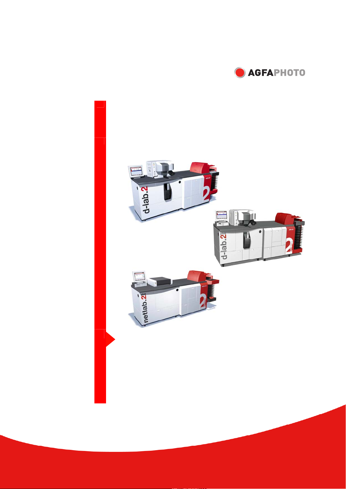
AgfaPhoto d-lab.2 8060/803, d-lab.2 8060/255, d-lab.2plus 8060/261, d-lab.2 8060/804, d-lab.2plus 8060/813 Operation Manual
...Page 1
Operation Manual
Digital Minilabs
d-lab.2plus:
8060/261
8060/813, 8060/814
8060/271, 8060/273
8060/158 + 8060/255
d-lab.2:
8060/260,
8060/803, 8060/804,
8060/270, 8060/272,
8060/157 + 8060/255
netlab.2plus:
8060/505
Operation
Order number DD+18060A162D0
Edition 2005-05-01
Version English, 04092_01
Page 2
Modification History
Version Edition Modifications
04092_00 2004-10-01
04092_01 2005_05_01
Combination of the Operation Manual – Operation
for the machines d-lab.2, d-lab.2plus, and
netlab.2plus;
Update to Software Version 8.0
Update to Software Version 8.5
© 2005 AgfaPhoto GmbH. Alle Rechte vorbehalten.
No part of these instructions may be reproduced, copied, or transmitted in any
form or by any means without prior written permission by AgfaPhoto GmbH.
AgfaPhoto is used under license of Agfa-Gevaert AG
Page 3

d-lab.2, d-lab.2plus, netlab.2plus: Operation Contents
Contents
Introduction........................................................................................................................1-i
1
1.1 Applied Standards and Rules....................................................................................................................................1-1
1.2 Explanations for the Operation and Service Manual.......................................................................................1-2
1.2.1 Available Documentation.......................................................................................................................1-2
1.2.2 Guideline for the User..............................................................................................................................1-3
1.2.3 Conventions.................................................................................................................................................1-4
1.2.3.1 Pictographs......................................................................................................................................1-4
1.2.3.2 Text styles........................................................................................................................................1-4
1.2.3.3 Safety notes.....................................................................................................................................1-5
1.3 Legal Situation ...............................................................................................................................................................1-6
1.3.1 Manufacturer Information......................................................................................................................1-6
1.3.2 Copyright ......................................................................................................................................................1-6
1.3.3 Warranty........................................................................................................................................................1-7
1.3.3.1 Liability of the Owner ..................................................................................................................1-7
1.3.3.2 Warranty and Liability .................................................................................................................1-7
1.3.3.3 Exclusion of Liability ....................................................................................................................1-8
1.3.4 Appropriate Use..........................................................................................................................................1-8
1.3.5 Inappropriate Use ......................................................................................................................................1-8
1.4 Consumables and Spare Parts..................................................................................................................................1-9
1.5 Hotline...............................................................................................................................................................................1-9
1.6 Safety Notes and Rules............................................................................................................................................1-10
1.6.1 General .......................................................................................................................................................1-10
1.6.2 In Operation..............................................................................................................................................1-11
1.6.3 Handling of Chemicals .........................................................................................................................1-11
1.6.4 Service / Repair Routines ...................................................................................................................1-12
1.6.5 Disposal of the Machine......................................................................................................................1-12
1.6.6 Warnings and Information Labels on the Machine ...................................................................1-13
1.7 Transport, Installation, First Operation ..............................................................................................................1-22
1.8 Storage ...........................................................................................................................................................................1-22
1.8.1 Chemicals..................................................................................................................................................1-22
1.8.2 Photographic Paper ...............................................................................................................................1-22
2 General Description, Work Routines and Operation ..............................................................2-i
2.1 General Description......................................................................................................................................................2-1
2.2 Product Description......................................................................................................................................................2-7
2.2.1 Corresponding Film Types and Images .............................................................................................2-7
2.2.2 Image Editing..............................................................................................................................................2-7
2.3 Operation Routines.......................................................................................................................................................2-8
2.3.1 Drive Bay
Applies only to d-lab.2plus, netlab.2plus................................................................................................2-8
2.3.2 Scanner
Applies only to d-lab.2/2plus ....................................................................................................................2-9
2.3.3 Main computer ........................................................................................................................................2-10
2.3.4 Printer .........................................................................................................................................................2-11
2.3.5 Paper Processor.......................................................................................................................................2-12
2.3.6 Sorter...........................................................................................................................................................2-13
2.3.7 Densitometer ...........................................................................................................................................2-14
2.4 Controls on the Minilab...........................................................................................................................................2-15
2.4.1 Keys and Pilot Lamps............................................................................................................................2-15
2.4.2 Touchscreen Monitor ............................................................................................................................2-16
AgfaPhoto 2005-05-01 / PN 04092_01 0-i
Page 4

Contents d-lab.2, d-lab.2plus, netlab.2plus: Operation
2.4.3 Main Breaker and Ground Fault Interrupter................................................................................. 2-17
2.5 Switching the Machine On and Off..................................................................................................................... 2-18
2.5.1 Preparations Prior to Switch-on........................................................................................................2-18
2.5.2 Automatic Switch-On (Timer) ............................................................................................................ 2-18
2.5.3 Switching On with the ON Key ......................................................................................................... 2-19
2.5.4 Switching the Machine On and Off with the Main Breaker................................................... 2-20
2.5.5 System Start.............................................................................................................................................2-22
2.5.6 User Login .................................................................................................................................................2-22
2.5.7 The Start Screen...................................................................................................................................... 2-23
2.5.8 Log-in of Another User .........................................................................................................................2-24
2.5.9 End of Work and Shutdown................................................................................................................2-24
2.5.9.1 Sleep Mode...................................................................................................................................2-25
2.5.9.2 Switching the Machine Off .....................................................................................................2-25
2.6 Screen Layout and Controls on the Screen......................................................................................................2-27
2.6.1 Information Area.....................................................................................................................................2-28
2.6.2 Buttons.......................................................................................................................................................2-30
2.6.3 Pulldown Menus.....................................................................................................................................2-31
2.6.4 Popup Windows ...................................................................................................................................... 2-32
2.6.5 Input Screens........................................................................................................................................... 2-34
2.6.5.1 Entering Text ................................................................................................................................2-34
2.6.5.2 Entering Numbers.......................................................................................................................2-35
2.6.6 Reorder Keyboard
Applies only to d-lab.2/2plus
................................................................................................................. 2-36
2.7 Main Menus .................................................................................................................................................................2-38
2.8 Calling Up Info ............................................................................................................................................................ 2-43
2.8.1 Film Drive Info
Applies only to d-lab.2/2plus
................................................................................................................. 2-45
2.8.2 Printer Info................................................................................................................................................2-46
2.8.3 Paper Processor Info .............................................................................................................................2-47
2.8.4 Order Info ..................................................................................................................................................2-48
2.8.5 Version Info .............................................................................................................................................. 2-49
2.8.6 Displaying the Error List....................................................................................................................... 2-50
2.9 Activating Help ...........................................................................................................................................................2-51
2.10 Ejecting the ZIP ..........................................................................................................................................................2-53
3 Changing Chemicals............................................................................................................ 3-i
3.1 Safety Information ........................................................................................................................................................3-1
3.2 Chemical Sets ................................................................................................................................................................3-3
3.3 Changing Chemical Solutions (MSC/d-lab Chemicals) .................................................................................3-4
3.4 Mixing Replenisher Chemicals (d-lab.2 Easy Paper Box)............................................................................ 3-10
3.5 Settings and Tests for the Chemicals.................................................................................................................3-11
4 Settings and Configurations ................................................................................................4-i
4.1 Overview...........................................................................................................................................................................4-1
4.2 Defining the User Interface, Defining Users, Assigning Rights...................................................................4-5
4.2.1 Defining the User Interface ...................................................................................................................4-5
4.2.2 Defining Users and User Rights ...........................................................................................................4-6
4.2.2.1 Defining a New User ...................................................................................................................4-7
4.2.2.2 Changing the Settings for an Existing User........................................................................ 4-9
4.2.2.3 Overview: Rights, which can be Assigned to a User......................................................4-10
4.2.2.4 Defining a User as Standard User.........................................................................................4-11
4.2.2.5 Changing the User .....................................................................................................................4-11
4.2.3 Deleting a User .......................................................................................................................................4-11
4.3 Defining Paper Width, Surfaces and Cut Lengths .........................................................................................4-12
4.3.1 Defining Paper Widths .........................................................................................................................4-12
0-ii 2005-05-01 / PN 04092_01 AgfaPhoto
Page 5

d-lab.2, d-lab.2plus, netlab.2plus: Operation Contents
4.3.2 Deleting Paper Widths .........................................................................................................................4-14
4.3.3 Defining Paper Surfaces.......................................................................................................................4-14
4.3.4 Renaming Surfaces ................................................................................................................................4-16
4.3.5 Deleting Surfaces ...................................................................................................................................4-16
4.3.6 Paper Codes according to AgfaPhoto Standard .......................................................................... 4-17
4.3.7 Defining Cut Lengths ............................................................................................................................4-18
4.3.8 Overview: Print Sizes ............................................................................................................................4-19
4.3.9 Deleting Cut Lengths............................................................................................................................4-20
4.4 Entering Machine Settings .....................................................................................................................................4-21
4.4.1 Setting Date and Time..........................................................................................................................4-22
4.4.2 Setting the Timer: Start and Shutdown..........................................................................................4-23
4.4.3 Defining the Standard User ................................................................................................................4-26
4.4.4 Installing / Activating Software .......................................................................................................4-27
4.4.4.1 Activating Software ...................................................................................................................4-27
4.4.4.2 Installing Software from CD................................................................................................... 4-29
4.4.5 Printer Settings .......................................................................................................................................4-30
4.4.6 Scanner Settings (Scratch Correction, Scanning Crop)
Applies only to d-lab.2/2plus
.................................................................................................................4-32
4.4.7 Paper Processor Settings.....................................................................................................................4-34
4.4.7.1 Setting the Replenishment Rates........................................................................................4-34
4.4.7.2 Setting the Temperatures and Calibrating the Sensors ...............................................4-36
4.4.7.3 Calibrating the Water Pumps ................................................................................................ 4-38
4.4.8 Other Settings..........................................................................................................................................4-43
4.4.8.1 General settings..........................................................................................................................4-44
4.4.8.2 Settings for negative printing
(only for d-lab.2/2plus)............................................................................................................4-45
4.4.8.3 Settings for digital orders........................................................................................................4-46
4.4.8.4 The dTFS function (digital Total Film Scanning: Image enhancement
in digital print files)................................................................................................................... 4-47
4.4.8.5 Autosave settings.......................................................................................................................4-49
4.5 Adjusting the Production Balance .......................................................................................................................4-50
4.5.1 General Information Regarding the Production Balance ........................................................ 4-53
4.5.2 Setting the Correction Impact (for Color Negatives and Digital).........................................4-54
4.5.3 Setting Sharpness - Edges (for Color Negatives and Digital) ................................................4-55
4.5.4 Setting the Saturation (for Color Negatives and Digital) ........................................................4-56
4.5.5 Setting Sharpness - Grain (for Color Negatives and Digital)..................................................4-57
4.5.6 Area Contrast (for Color Negatives and Digital)..........................................................................4-58
4.5.7 Setting Detail Contrast (for Color Negatives and Digital)....................................................... 4-59
4.5.8 Brightness correction (for color negatives and digital)............................................................4-60
4.5.9 Setting Color and Density Corrections (Digital) .........................................................................4-61
4.5.10 Activating / Deactivating the Contrast Management (only for Color Negative)
Applies only to d-lab.2/2plus
.................................................................................................................4-61
4.5.11 Red-eye correction (for color negatives and digital)................................................................. 4-61
4.5.12 Using TFS (only for Color Negatives)
Applies only to d-lab.2/2plus
.................................................................................................................4-63
4.5.13 Panorama Identification (only for Color Negatives)
Applies only to d-lab.2/2plus
.................................................................................................................4-65
4.5.14 Color / Density Logic (TFS; only for Color Negative)
Applies only to d-lab.2/2plus
.................................................................................................................4-65
4.5.15 Setting TFS Color (only for Color Negatives)
Applies only to d-lab.2/2plus
4.5.15.1 Dominant Parameters...............................................................................................................4-66
4.5.15.2 Parameters for Artificial Light Detection...........................................................................4-68
4.5.15.3 Parameter for Shift Correction...............................................................................................4-70
.................................................................................................................4-66
AgfaPhoto 2005-05-01 / PN 04092_01 0-iii
Page 6

Contents d-lab.2, d-lab.2plus, netlab.2plus: Operation
4.5.16 Setting TFS Density (only for Color Negatives)
Applies only to d-lab.2/2plus
................................................................................................................. 4-71
4.5.17 Setting the Selector Logic (only for Color Negatives)
Applies only to d-lab.2/2plus
................................................................................................................. 4-73
4.5.18 Setting Color and DX Corrections (for Color Negatives)
Applies only to d-lab.2/2plus
4.5.18.1 Color Corrections........................................................................................................................4-75
4.5.18.2 DX Corrections ............................................................................................................................4-76
................................................................................................................. 4-75
4.6 Settings for Network Orders ..................................................................................................................................4-78
4.6.1 Settings for Remote Orders: File Print ...........................................................................................4-79
4.6.2 Settings for Remote Orders: Autosave ........................................................................................... 4-80
4.6.3 Settings for Network Orders............................................................................................................... 4-81
4.6.4 Settings for d-workflow........................................................................................................................ 4-82
4.7 Defining and Editing Print Configurations .......................................................................................................4-84
4.7.1 Defining and Editing Paper Configurations.................................................................................. 4-85
4.7.2 Defining and Editing the Backprint Configurations ..................................................................4-87
4.7.3 Indexprint Configurations....................................................................................................................4-93
4.7.3.1 Importing Indexprint Layouts.................................................................................................4-93
4.7.3.2 Defining and Editing a Indexprint Configuration:...........................................................4-94
4.7.4 Defining and Editing Correction Configurations ........................................................................4-97
4.7.5 Defining and Editing Autosave Configurations.........................................................................4-100
4.7.6 Defining and Editing a Front Print Configuration ....................................................................4-104
4.7.7 Combiprint Configurations ...............................................................................................................4-106
4.7.7.1 Importing Combiprint Layouts............................................................................................ 4-106
4.7.7.2 Defining and Editing a Combiprint Configurations:.................................................... 4-107
4.8 Defining and Editing Order Configurations....................................................................................................4-109
4.8.1 Defining and Editing Order Configurations of the Single Type...........................................4-112
4.8.1.1 Film Mask: 135, 120, 110
Applies only to d-lab.2/2plus............................................................................................. 4-112
4.8.1.2 Film Mask: File Print...............................................................................................................4-113
4.8.1.3 Film Mask: IX240
Applies only to d-lab.2/2plus............................................................................................. 4-115
4.8.1.4 Film Mask: Slide
Applies only to d-lab.2/2plus............................................................................................. 4-117
4.8.2 Defining and Editing Order Configurations of the Package Type ......................................4-118
4.8.3 Defining and Editing Order Configurations of the Combiprint Type.................................4-120
4.8.3.1 Film Mask: 135, 120, 110
Applies only to d-lab.2/2plus............................................................................................. 4-120
4.8.3.2 Film Mask: IX240, Slide
Applies only to d-lab.2/2plus............................................................................................. 4-121
4.8.3.3 Film Mask: File Print...............................................................................................................4-122
4.8.4 Defining and Editing Order Configurations of the Reproduction Type ............................4-123
4.8.5 Defining a Configuration as Standard Configuration..............................................................4-125
4.9 Deleting a Print or Order Configuration ..........................................................................................................4-127
4.10 Pricing Configurations............................................................................................................................................4-128
4.11 Save and Load Settings and Configurations..................................................................................................4-129
5 Tests.................................................................................................................................. 5-i
5.1 Overview...........................................................................................................................................................................5-1
5.2 Printer Tests:Paper Balance Test (PBL) and Master Balance Test (MBL)..................................................5-2
5.2.1 Conditions for Printing an MBL and PBL..........................................................................................5-3
5.2.2 Initial PBL and MBL after the Machine Installation.....................................................................5-4
5.2.3 Daily Calibration with the MBL............................................................................................................5-5
5.2.4 Daily Calibration without MBL (Exception) .....................................................................................5-6
0-iv 2005-05-01 / PN 04092_01 AgfaPhoto
Page 7

d-lab.2, d-lab.2plus, netlab.2plus: Operation Contents
5.2.5 Calibration of a New Paper Configuration in Case of Emulsion Changes
or Changes in a Paper Configuration (not Master Paper)...........................................................5-6
5.2.6 Calibrating a New Paper Configuration or Changing the Emulsion
(Master Paper).............................................................................................................................................5-7
5.2.7 Complete New Calibration.....................................................................................................................5-8
5.3 Printing a PBL Test .......................................................................................................................................................5-9
5.3.1 General Procedure.....................................................................................................................................5-9
5.3.2 PBL Test with Laser Point....................................................................................................................5-11
5.3.3 Copying Laser Points during Calibration of a Paper Configuration.....................................5-12
5.3.4 Default Setting of Maximum Densities and Calibration Factors..........................................5-14
5.3.5 When Should Maximum Densities Be Changed? .......................................................................5-15
5.3.6 Changing the Maximum Densities of a Paper............................................................................. 5-16
5.3.7 Changing the Gray Balance of the Internal Densitometer.....................................................5-19
5.4 Printing an MBL Test.................................................................................................................................................5-20
5.5 Calibrating the Scanner (Pixel Correction, PIKO)
Applies only to d-lab.2/2plus
.....................................................................................................................................5-21
5.6 Checking the Process (Chemical control strip test)......................................................................................5-23
6 Production..........................................................................................................................6-i
6.1 Order Handling – Overview.......................................................................................................................................6-1
6.1.1 Preparations Before Production Start ................................................................................................6-1
6.1.2 Print Modes..................................................................................................................................................6-2
6.1.2.1 Print modes and Possible Film and File Formats ..............................................................6-2
6.1.2.2 Printing without or with Preview.............................................................................................6-4
6.1.2.3 Order Configurations....................................................................................................................6-5
6.1.2.4 Changing to another print mode.............................................................................................6-5
6.1.3 Order Handling ...........................................................................................................................................6-6
6.1.4 Order Tracing............................................................................................................................................6-10
6.1.5 Changing the Order Number..............................................................................................................6-10
6.1.6 Select or Change Configuration........................................................................................................6-11
6.1.6.1 Configuration Types for Print Orders................................................................................... 6-11
6.1.6.2 Display of the Current Configuration..................................................................................6-12
6.1.6.3 Changing the Configuration for the Complete Order....................................................6-16
6.1.6.4 Changing the Configuration for Individual Images of an Order
Applies only to d-lab.2/2plus................................................................................................6-17
6.1.6.5 Selecting Another Configuration for the Complete Order...........................................6-18
6.1.6.6 Selecting Another Configuration for Individual Images of an Order
Applies only to d-lab.2/2plus................................................................................................6-18
6.1.7 Inserting Films and Slides
Applies only to d-lab.2/2plus
.................................................................................................................6-19
6.1.8 End of Order (Automatic / Manual).................................................................................................6-20
6.1.9 Special Print Products and Motif Groups ......................................................................................6-21
6.1.9.1 Black and White Prints.............................................................................................................6-21
6.1.9.2 Sepia Prints and Prints with Color Cast.............................................................................6-23
6.1.9.3 Reorder
Applies only to d-lab.2/2plus of Black/White Films / Films Without
Extended DX Code.....................................................................................................................6-23
6.1.9.4 Portraits..........................................................................................................................................6-24
6.1.9.5 Border Prints ................................................................................................................................6-24
6.2 Preparing the Machine for Different Orders.....................................................................................................6-26
6.2.1 Changing the Paper Magazine and Loading Paper ...................................................................6-26
6.2.1.1 Removing the Paper Magazine.............................................................................................6-27
6.2.1.2 Removing the Paper..................................................................................................................6-27
6.2.1.3 Adjusting the Paper Widths....................................................................................................6-28
6.2.1.4 Loading Paper into the Magazine........................................................................................6-29
AgfaPhoto 2005-05-01 / PN 04092_01 0-v
Page 8

Contents d-lab.2, d-lab.2plus, netlab.2plus: Operation
6.2.1.5 Coding the Paper Magazine ...................................................................................................6-30
6.2.1.6 Inserting a Paper Magazine....................................................................................................6-30
6.2.2 Changing the Mirror Box
Applies only to d-lab.2/2plus
................................................................................................................. 6-31
6.2.3 Changing the Film Carrier
Applies only to d-lab.2/2plus
................................................................................................................. 6-32
6.3 Printing .......................................................................................................................................................................... 6-33
6.3.1 Working with the Autoprint Mode
Applies only to d-lab.2/2plus
6.3.1.1 Activating the Print Mode and Selecting a Configuration..........................................6-33
6.3.1.2 Autoprint without Preview......................................................................................................6-34
6.3.1.3 Autoprint with Preview.............................................................................................................6-35
................................................................................................................. 6-33
6.3.2 Working with Reorder Mode
Applies only to d-lab.2/2plus
6.3.2.1 Activating the Print Mode and Editing a Reorder List ..................................................6-40
6.3.2.2 Reorder without Preview .........................................................................................................6-44
6.3.2.3 Reorder with Preview................................................................................................................6-46
................................................................................................................. 6-40
6.3.3 Working with Manual Positioning Mode
Applies only to d-lab.2/2plus
6.3.3.1 Activating the Print Mode.......................................................................................................6-51
6.3.3.2 Image Editing and Printing.....................................................................................................6-52
................................................................................................................. 6-50
6.3.4 Working with File Print Mode ...........................................................................................................6-55
6.3.4.1 General Information ..................................................................................................................6-55
6.3.4.2 Using dTFS: Automatic Color and Density Corrections.................................................6-57
6.3.4.3 Load Image Files from Storage Media................................................................................6-58
6.3.4.4 Saving Digital Orders ................................................................................................................6-61
6.3.4.5 Loading a Saved Digital Order...............................................................................................6-62
6.3.4.6 Delete the Saved Digital Order .............................................................................................6-64
6.3.4.7 Printing File Prints without Preview....................................................................................6-65
6.3.4.8 Printing File Prints with Preview..........................................................................................6-67
6.3.5 Working with Slide Print Mode
Applies only to d-lab.2/2plus
6.3.5.1 Activating the Print Mode.......................................................................................................6-72
6.3.5.2 Image Editing and Printing.....................................................................................................6-74
................................................................................................................. 6-72
6.3.6 Working with the Slide Film Print Mode
Applies only to d-lab.2/2plus................................................................................................................. 6-76
6.3.6.1 Activating the Print Mode.......................................................................................................6-76
6.3.6.2 Image Editing and Printing.....................................................................................................6-77
6.4 The Functions Image Editing and Special ........................................................................................................ 6-80
6.4.1 Image Editing........................................................................................................................................... 6-81
6.4.1.1 Activation ......................................................................................................................................6-81
6.4.1.2 Making Color and Density Corrections...............................................................................6-82
6.4.1.3 Cropping ........................................................................................................................................6-83
6.4.1.4 Image Improvement..................................................................................................................6-84
6.4.2 Special........................................................................................................................................................6-85
6.4.2.1 Enter and Format Text for the Exposure.............................................................................6-86
6.4.2.2 Setting a Border..........................................................................................................................6-88
6.4.3 Saving an Image as File.......................................................................................................................6-89
6.5 Manual red eyes correction ...................................................................................................................................6-91
6.6 Index prints...................................................................................................................................................................6-95
6.6.1 Index Prints in the Different Print Modes ..................................................................................... 6-96
6.6.2 Sequence and Designations of the Thumbnails......................................................................... 6-97
6.6.3 Quantity, Size, and Aspect Ratio of the Thumbnails ................................................................6-97
6.6.4 Print Index Print Only ........................................................................................................................... 6-98
0-vi 2005-05-01 / PN 04092_01 AgfaPhoto
Page 9

d-lab.2, d-lab.2plus, netlab.2plus: Operation Contents
6.7 Saving Images with Autosave ...............................................................................................................................6-99
6.7.1 Printing and Saving Images ............................................................................................................ 6-100
6.7.2 Save Images Only, Without Printing............................................................................................ 6-101
6.8 Network Orders ........................................................................................................................................................ 6-102
6.8.1 The Minilab in a Network................................................................................................................. 6-102
6.8.2 Manual Start of Network Orders.................................................................................................... 6-104
6.8.3 Automatic Start of Network Orders .............................................................................................. 6-105
6.8.4 Deleting Network Orders.................................................................................................................. 6-106
6.9 Printing Price Labels (Option) ........................................................................................................................... 6-107
6.10 Saving and Displaying Statistics....................................................................................................................... 6-108
6.10.1 Displaying Statistics........................................................................................................................... 6-108
6.10.2 Saving Statistics................................................................................................................................... 6-109
6.11 Clickrate (Option) .................................................................................................................................................... 6-110
7 Troubleshooting..................................................................................................................7-i
7.1 Avoiding Problems........................................................................................................................................................7-1
7.2 Display of Error Messages ..........................................................................................................................................7-2
7.3 Activating Help for Error Messages........................................................................................................................7-3
7.4 Problems During Scanning
Applies only to d-lab.2/2plus
7.5 The Machine Fails to React to Operator Inputs.................................................................................................7-4
7.5.1 Resetting the Machine with the Stop Button................................................................................7-5
7.5.2 Resetting the Machine with the ON key..........................................................................................7-6
7.6 Procedure if an Error Occurs .....................................................................................................................................7-8
7.6.1 General Procedure.....................................................................................................................................7-8
7.6.2 Procedure for Unsolved Errors ..............................................................................................................7-8
7.6.3 Screen Remains Gray for More Than 3 Minutes after Reset .....................................................7-9
7.6.4 Image Processing Errors.......................................................................................................................7-10
7.6.5 Paper Processor and Printer Errors...................................................................................................7-11
7.6.6 Printer Errors.............................................................................................................................................7-12
7.6.7 Other Errors...............................................................................................................................................7-12
7.7 Removing a Paper Jam
Applies to d-lab.2 ..........................................................................................................................................................7-13
7.7.1 General procedure..................................................................................................................................7-13
7.7.2 Paper Jam in the Printer......................................................................................................................7-15
7.7.3 Paper Jam in the Transport Unit (TU)..............................................................................................7-16
7.7.4 Paper Jam in the Transfer Positions Transport Unit (TU) and Print Engine (PE)..............7-20
7.7.5 Paper Jam in the Print Engine (PE) ..................................................................................................7-21
7.7.6 Paper Jam between Transport Unit (TU) and
Lane Distributor (LD)..............................................................................................................................7-23
7.7.7 Paper Jam in the Lane Distributor (LD) ..........................................................................................7-24
7.7.8 Paper Jam between Lane Distributor (LD) and
Sheet Transfer (ST)..................................................................................................................................7-25
7.7.9 Paper Jam in the Paper Processor....................................................................................................7-26
7.7.10 Paper jam between dryer and paper outlet..................................................................................7-27
7.8 Removing a Paper Jam
Applies to d-lab.2plus/netlab.2plus.......................................................................................................................... 7-28
7.8.1 General procedure..................................................................................................................................7-28
7.8.2 Paper Jam in the Printer......................................................................................................................7-30
7.8.3 Paper Jam in the Feeder Unit FU......................................................................................................7-31
7.8.4 Paper Jam in the Transfer Positions between Feeder Unit FU and Print
Machine PM..............................................................................................................................................7-35
7.8.5 Paper Jam in the Print Machine PM ...............................................................................................7-36
........................................................................................................................................7-3
AgfaPhoto 2005-05-01 / PN 04092_01 0-vii
Page 10

Contents d-lab.2, d-lab.2plus, netlab.2plus: Operation
7.8.6 Paper Jam between the Feeder Unit FU and Sheet Distributor SD..................................... 7-38
7.8.7 Paper Jam in the Sheet Distributor SD ..........................................................................................7-39
7.8.8 Paper Jam between Sheet Distributor SD and Sheet Transfer ST........................................ 7-40
7.8.9 Paper Jam in the Paper Processor ................................................................................................... 7-41
7.8.10 Paper Jam between dryer and outlet unit .................................................................................... 7-42
8 Maintenance ...................................................................................................................... 8-i
8.1 Safety Instructions........................................................................................................................................................8-1
8.2 Maintenance Routines – Schedule and Overview...........................................................................................8-2
8.3 Daily Maintenance .......................................................................................................................................................8-8
8.3.1 Cleaning the APS Film Carrier
Applies only to d-lab.2/2plus
....................................................................................................................8-8
8.3.2 Cleaning the Drive Rollers in the Film Carrier
Applies only to d-lab.2/2plus
8.3.2.1 In the Running Machine ..........................................................................................................8-10
8.3.2.2 When the Machine is Off.........................................................................................................8-10
................................................................................................................. 8-10
8.3.3 Cleaning the Film Brushes
Applies only to d-lab.2/2plus
................................................................................................................. 8-11
8.3.4 Running a Process Check in the Paper Processor .....................................................................8-11
8.4 Weekly Maintenance Routines.............................................................................................................................8-12
8.4.1 Cleaning the Film Carrier
Applies only to d-lab.2/2plus
................................................................................................................. 8-12
8.4.2 Cleaning the Film Takeup
Applies only to d-lab.2/2plus
................................................................................................................. 8-12
8.4.3 Cleaning the Film Chute
Applies only to d-lab.2/2plus
................................................................................................................. 8-13
8.4.4 Remove Paper Dust
Applies to d-lab.2 ...................................................................................................................................... 8-14
8.4.4.1 Transport Unit (TU) .....................................................................................................................8-14
8.4.4.2 Single sheet buffer (SR) and sheet bridge (SB)................................................................8-15
8.4.4.3 Print engine (PE): Remove Paper Dust ...............................................................................8-16
8.4.4.4 Lane distributor (LD): Remove Paper Dust and Deposits .............................................8-19
8.4.4.5 Sheet Transfer (ST)......................................................................................................................8-20
8.4.5 Remove Paper Dust
Applies to d-lab.2plus and netlab.2plus............................................................................................... 8-21
8.4.5.1 Feeder Unit (FU) ..........................................................................................................................8-21
8.4.5.2 Sheet Stocker (SR) and Sheet Bridge (SB).........................................................................8-23
8.4.5.3 Print Machine (PM)....................................................................................................................8-24
8.4.5.4 Sheet Distributor (SD): Remove Paper Dust and Deposits ..........................................8-27
8.4.5.5 Sheet Transfer (ST)......................................................................................................................8-28
8.4.6 Paper Processor: Cleaning the CD Feed Unit, Tank Crossovers, and the
Squeegee Unit......................................................................................................................................... 8-29
8.4.7 Checking the Solution Levels............................................................................................................8-33
8.4.8 Cleaning the Chemical Filters...........................................................................................................8-34
8.4.9 Cleaning the Filters in the ASTOR and Water Inlets................................................................. 8-35
8.4.10 Cleaning the Densitometer Calibration Plate ............................................................................. 8-36
8.4.11 Lane shifter (LS): Cleaning the transport belt.............................................................................. 8-38
8.5 Monthly Maintenance Routines........................................................................................................................... 8-39
8.5.1 Cleaning the Exposure Filters
Applies only to d-lab.2/2plus
................................................................................................................. 8-39
8.5.2 Checking and Calibrating the Solution Temperatures............................................................. 8-41
8.5.3 Cleaning or Replacing the Air Filters.............................................................................................. 8-41
8.5.4 Replacing the Scanner Lamp and Resetting the Operation Counter
Applies only to d-lab.2/2plus
................................................................................................................. 8-45
8.5.5 Replacing the Chemical Filters.........................................................................................................8-47
0-viii 2005-05-01 / PN 04092_01 AgfaPhoto
Page 11

d-lab.2, d-lab.2plus, netlab.2plus: Operation Contents
8.5.6 Cleaning the Processing Racks.........................................................................................................8-48
8.5.7 Cleaning the Dryer Rack......................................................................................................................8-51
8.5.8 Clean the paper outlet (PO)................................................................................................................8-53
8.6 Maintenance Routines Every 6 Months.............................................................................................................8-57
8.6.1 Cartridge feeder: Cleaning the Mechanism and Light Barriers
Applies only to d-lab.2/2plus
.................................................................................................................8-57
8.7 Maintenance When Required ................................................................................................................................8-57
8.7.1 Removing the Dust from the Lens
Applies only to d-lab.2/2plus
.................................................................................................................8-57
8.7.2 Back Printer: Replacing the Ink Ribbon.........................................................................................8-58
8.7.3 Emptying the Effluent Tanks ..............................................................................................................8-60
8.8 Spare Parts and Accessories ..................................................................................................................................8-62
9 Technical Data....................................................................................................................9-i
9.1 Machine versions ..........................................................................................................................................................9-1
9.2 Complete System..........................................................................................................................................................9-1
9.3 Main Computer ..............................................................................................................................................................9-5
9.4 Prescanner / Scanner
Applies only to d-lab.2/2plus........................................................................................................................................9-6
9.5 Printer ................................................................................................................................................................................9-7
9.6 Paper Processor .............................................................................................................................................................9-8
9.7 Heat Emission .................................................................................................................................................................9-9
9.8 Operating Conditions................................................................................................................................................9-10
9.9 Storage and Transport ..............................................................................................................................................9-10
9.10 Consumables and Operating Materials..............................................................................................................9-10
10 Environmental Protection and Disposal ..............................................................................10-i
10.1 Handling of Chemicals.............................................................................................................................................10-1
10.1.1 Legal Regulations...................................................................................................................................10-1
10.1.2 Disposal......................................................................................................................................................10-1
10.1.2.1 Exhausted Processing Solutions...........................................................................................10-1
10.1.2.2 Liquid Residues ...........................................................................................................................10-2
10.1.2.3 Chemical Containers.................................................................................................................10-2
10.1.2.4 Chemical Filters..........................................................................................................................10-2
10.2 Energy Saving Hints ..................................................................................................................................................10-2
11 Machine Shutdown............................................................................................................11-i
11.1 Machine Shutdown (Down Time up to 2 Weeks)...........................................................................................11-1
11.2 Machine Shutdown (Down Time longer than 2 Weeks)..............................................................................11-2
11.3 Resuming Operation .................................................................................................................................................11-3
11.4 Final Machine Shutdown.........................................................................................................................................11-4
11.5 Deinstalling the Machine .......................................................................................................................................11-4
12 List of Abbreviations and Glossary ....................................................................................12-1
13 Index...............................................................................................................................13-1
14 Appendix ..........................................................................................................................14-i
14.1 Conformity Declaration............................................................................................................................................. 14-i
AgfaPhoto 2005-05-01 / PN 04092_01 0-ix
Page 12

Contents d-lab.2, d-lab.2plus, netlab.2plus: Operation
■
0-x 2005-05-01 / PN 04092_01 AgfaPhoto
Page 13

d-lab.2, d-lab.2plus, netlab.2plus: Operation Introduction
1 Introduction
1.1
Applied Standards and Rules....................................................................................................................................1-1
1.2 Explanations for the Operation and Service Manual.......................................................................................1-2
1.2.1 Available Documentation.......................................................................................................................1-2
1.2.2 Guideline for the User..............................................................................................................................1-3
1.2.3 Conventions.................................................................................................................................................1-4
1.2.3.1 Pictographs......................................................................................................................................1-4
1.2.3.2 Text styles........................................................................................................................................1-4
1.2.3.3 Safety notes.....................................................................................................................................1-5
1.3 Legal Situation ...............................................................................................................................................................1-6
1.3.1 Manufacturer Information......................................................................................................................1-6
1.3.2 Copyright ......................................................................................................................................................1-6
1.3.3 Warranty........................................................................................................................................................1-7
1.3.3.1 Liability of the Owner ..................................................................................................................1-7
1.3.3.2 Warranty and Liability .................................................................................................................1-7
1.3.3.3 Exclusion of Liability ....................................................................................................................1-8
1.3.4 Appropriate Use..........................................................................................................................................1-8
1.3.5 Inappropriate Use ......................................................................................................................................1-8
1.4 Consumables and Spare Parts..................................................................................................................................1-9
1.5 Hotline...............................................................................................................................................................................1-9
1.6 Safety Notes and Rules............................................................................................................................................1-10
1.6.1 General .......................................................................................................................................................1-10
1.6.2 In Operation..............................................................................................................................................1-11
1.6.3 Handling of Chemicals .........................................................................................................................1-11
1.6.4 Service / Repair Routines ...................................................................................................................1-12
1.6.5 Disposal of the Machine......................................................................................................................1-12
1.6.6 Warnings and Information Labels on the Machine ...................................................................1-13
1.7 Transport, Installation, First Operation ..............................................................................................................1-22
1.8 Storage ...........................................................................................................................................................................1-22
1.8.1 Chemicals..................................................................................................................................................1-22
1.8.2 Photographic Paper ...............................................................................................................................1-22
1
AgfaPhoto 2005-05-01 / PN 04092_01 1-i
Page 14

Introduction d-lab.2, d-lab.2plus, netlab.2plus: Operation
■
1-ii 2005-05-01 / PN 04092_01 AgfaPhoto
Page 15

d-lab.2, d-lab.2plus, netlab.2plus: Operation Introduction
1.1 Applied Standards and Rules
1
The machine is in compliance with the requirements of the standards and rules listed
below:
98/37/EG:
Machine Directives
73/23/EWG:
Directive for Low Voltage
89/336/EWG:
Electromagnetic Compatibility (according to Modifications 91/ 263/EEC and 2/31/EEC)
EN 60950:
Safety of Information Technology Equipment
EN 60825-1:
Safety of Laser Equipment
EN 55022:
Information Technology Equipment – Radio interference – Limits and Methods of
Measurements
EN 55024:
Information Technology Equipment – Immunity Standard - Limits and Methods of
Measurements
EN 61000-6-2:
Electromagnetic Compatibility (EMC) - Part 6-2: Basic Standard; Immunity Standard for
Industrial Areas (IEC 61000-6-2:1999, modified)
EN 61000-3-2:
Electromagnetic Compatibility (EMC) - Part 3-2: Limit Values - Limit Values for Harmonic
Emissions (IEC 61000-3-2:2000, modified)
EN 61000-3-3:
Electromagnetic Compatibility (EMC) - Part 3-3: Limit Values – Limitation of voltage
changes, voltage fluctuations and flicker in public low voltage supply networks for
equipment with a current <= 16 A per conductor, which are not subject to any special
connection conditions (IEC 61000-3-3:1994 + A1:2001)
AgfaPhoto 2005-05-01 / PN 04092_01 1-1
Page 16

Introduction d-lab.2, d-lab.2plus, netlab.2plus: Operation
1.2 Explanations for the Operation and Service Manual
1.2.1 Available Documentation
The complete Operation and Service Manual comprises of several documents (see
table below).
Operation Manuals Owner Photo-
Technician
Assistant
Operation
Installation
●
●
●
Service Manuals Owner Photo-
Technician
Assistant
Repair
Parts List
Circuit Diagrams
Preinstallation
●
●
●
●
●
The customer receives the “Preinstallation” instructions when the machine is ordered.
The Operation Manuals “Installation” and “Operation” are included with the machine
shipment. The “Operation” folder includes a CD with the complete Operation Manual
(except circuit diagrams).
All other sections of the Operation and Service Manual can be ordered from AgfaPhoto.
The Operation Manuals “Installation” and “Operation” must be kept around the machine
to ensure that all users have access to these instructions.
The Operation Instructions section "Operation" applies to the following machines:
Machines with gas laser:
d-lab.2 Type 8060/260
d-lab.2plus Type 8060/261
Machines with solid state laser:
d-lab.2 select Type 8060/803 and Type 8060/804
d-lab.2 basic Type 8060/270 and Type 8060/272
d-lab.2 (70mm) Type 8060/157 + 8060/255
d-lab.2plus select Type 8060/813 and Type 8060/814
d-lab.2plus basic Type 8060/271 and Type 8060/273
d-lab.2plus (70mm) Type 8060/158 + 8060/255
netlab.2plus basic Type 8060/505
1-2 2005-05-01 / PN 04092_01 AgfaPhoto
Page 17

d-lab.2, d-lab.2plus, netlab.2plus: Operation Introduction
1.2.2 Guideline for the User
Operation / Service Manual Contents
1
Preinstallation
Installation The machine is delivered by a forwarding company.
Operation The “Operation” section of the Operation Manual includes all important
The owner takes care of the listed preinstallation measures and returns the
checklist to AgfaPhoto no later than two weeks prior to the installation date.
This “Installation” section of the Operation Manual describes the transport to the
operation site, as well as the installation and implementation of the machine.
The machine is installed by an AgfaPhoto authorized technician and put in
operation.
information required to ensure operation:
Chapter 1:
Notes on the Operation Manual, legal notes, safety notes, transport and storage.
Chapter 2:
Introduction of the components, functions and controls of the machine, help
function and information.
Chapter 3:
Description of the mixing process for chemicals.
Chapter 4:
Prior to production the Minilab must be set up to meet the requirements of the
laboratory (machine settings) and the order handling (print configurations).
Chapter 5:
Description of the tests, which ensure the production quality.
Chapter 6:
Step by step description of the order handling.
Chapter 7:
Description of possible problems, which may be solved by the customer.
Chapter 8:
Description of the required maintenance routines on the machine.
Chapter 9:
Listing of the technical specifications of the Minilab.
AgfaPhoto 2005-05-01 / PN 04092_01 1-3
Page 18
Introduction d-lab.2, d-lab.2plus, netlab.2plus: Operation
Operation / Service Manual
Operation (continued) Chapter 10:
Contents
Description of measures for environmental protection and the disposal of the
machine.
Chapter 11:
Description of measures for closing down a machine.
Chapter 12:
Explanation of the abbreviations and special terms used in these instructions.
Chapter 13:
Key Word Index
Chapter 14:
Appendix
1.2.3 Conventions
1.2.3.1 Pictographs
The symbols used in the instructions have the following meaning:
Operating steps
Result of the operating step
This symbol is used for warning notes.
Special tools
1.2.3.2 Text styles
The following text passages are emphasized by bold print /
1. Screen designations
Example: Pressing OK will validate the displayed text and close the dialog window.
2. Button designations
Example: Press the Reorder button to edit reorders.
3.
Italic print
Example: see paragraphs
pages.
is used for reference to chapters or paragraphs.
Menu Overview
and
Screen Structure
italic print
on the following
in this manual:
1-4 2005-05-01 / PN 04092_01 AgfaPhoto
Page 19
d-lab.2, d-lab.2plus, netlab.2plus: Operation Introduction
1.2.3.3 Safety notes
The following “keywords” are used in these instructions and on machine labels:
1
Note
Indicates additional information on the respective subject or the possibility of operating
errors.
CAUTION!
This indicates a potential danger which may result in medium or minor personal injuries
or property damage.
WARNING!
Indicates a possible risk involved with a product which in case of non-observance may
result in severe personal injuries or even death.
AgfaPhoto 2005-05-01 / PN 04092_01 1-5
Page 20

Introduction d-lab.2, d-lab.2plus, netlab.2plus: Operation
1.3 Legal Situation
The operation of the machines is ruled by the appropriate regulations for the place of
installation in force in the country concerned.
This Operation Manual includes an EU Conformity Declaration (CE) about the applying
harmonized standards (see
The warning notes in these instructions as well as the warnings and instructions on
machine labels must be observed by all means.
Non-observance may be hazardous to your health, and may result in damage on
equipment and buildings: injuries, electric shocks, fire.
Manufacturer and Service will not assume any responsibilities for accidents and damage
resulting from inappropriate operation.
Appendix
).
1.3.1 Manufacturer Information
AgfaPhoto GmbH
PO box 900151
D-81536 München, Germany
1.3.2 Copyright
Copies of photographs, negatives and other pictures must not be made without the
permission of the author. Under normal conditions, the copyright is the property of the
photographer. The person who orders the copy is not always the author of the material.
1-6 2005-05-01 / PN 04092_01 AgfaPhoto
Page 21

d-lab.2, d-lab.2plus, netlab.2plus: Operation Introduction
1.3.3 Warranty
1.3.3.1 Liability of the Owner
1
Warranty and availability clauses are subject to the following conditions:
– The Minilab is only operated by persons who participated in the detailed AgfaPhoto
training and are able to proof this.
– The required power supply for the operation of the Minilab, as well as chemicals and
other consumables must be provided according to the instructions.
–
All instructions regarding the operation and maintenance of the Minilab as given by
AgfaPhoto must be followed.
– Maintenance of the machine must be performed in compliance with the instructions
given by AgfaPhoto.
– The use of other wear and tear parts or spare parts than the original parts by AgfaPhoto
results in immediate termination of warranty, availability and guaranty claims.
1.3.3.2 Warranty and Liability
The equipment has been built and tested in compliance with the standards and rules as
listed in the section
Applied Standards and Rules
, and left the factory in perfect and safe
working condition. To keep this condition and guarantee an operation without any risks,
the user must observe the notes and warnings in this Operation Manual. Owner and user
will be liable and must ensure that all safety features and devices, as well as the
conditions in the machine environment are provided and followed in a suitable measure.
The general terms and conditions of sales and delivery of the AgfaPhoto GmbH apply as a
matter of principle. The owner receives these terms at the time of contract conclusion or
before.
Warranty and liability claims in case of personal injuries and property damage are
excluded if they are the result of one or more of the following causes:
– improper use of the Minilab;
– incorrect assembly, operation, handling or maintenance of the Minilab;
– non-observance of notes in the Operation Manual with respect to transport, storage,
assembly, switch-on, operation, and maintenance of the equipment;
– high-handed changes on the Minilab;
– inadequate monitoring of assemblies of the
Minilab, which are subject to wear and tear;
– incorrectly made repairs;
– catastrophic cases that are due to external impacts and force majeure.
A correct and safe operation of the equipment also requires correct transport, correct
storage, correct installation and assembly, as well as careful operation and service.
Guaranty regulations are up to the countries. For information refer to the sales contract or
the warranty certificate.
AgfaPhoto 2005-05-01 / PN 04092_01 1-7
Page 22

Introduction d-lab.2, d-lab.2plus, netlab.2plus: Operation
1.3.3.3 Exclusion of Liability
AgfaPhoto tested the contents of this Operation Manual regarding the correspondence
with the described hardware and software. However, deviations cannot be excluded
completely and AgfaPhoto will not accept a guarantee for complete correspondence. The
information in this Operation Manual is checked and revised in regular intervals and the
required corrections will be included in the following editions.
We reserve the right to technical changes.
1.3.4 Appropriate Use
Applies to d-lab.2/2plus
The d-lab.2/2plus is a digital minilab
– to print negative films, slides, and images from digital sources on photographic paper,
and
– to save digital data on digital storage media.
Applies to netlab.2plus
The netlab.2plus is a digital minilab
– to print images from digital sources on photographic paper, and
– to save digital data on digital storage media.
The Minilab must only be used for purposes described in these instructions and in
combination with the components and consumables recommended and/or admitted by
AgfaPhoto. Further use outside these specifications is considered as inappropriate use.
AgfaPhoto will not be liable for any damage resulting from inappropriate use.
The appropriate use also includes:
– the observance of all notes in the Installation and Operation Instructions;
– the performance of inspection and maintenance routines.
The equipment must only be operated by qualified professional staff. Qualified personnel
in accordance with this Operation Manual are persons specially trained by AgfaPhoto for
the operation of the equipment.
1.3.5 Inappropriate Use
Inappropriate use (misuse) will be:
– any application not corresponding to the afore mentioned appropriate use or use
outside the specifications;
– the nonobservance of the instructions in the Operation Manual;
– the nonobservance of the safety rules;
– if problems which may affect the safety are not immediately solved before normal
operation is resumed (operation of the machine in a condition, which is not correct
regarding functional and safety aspects);
– any unauthorized changes on the equipment.
1-8 2005-05-01 / PN 04092_01 AgfaPhoto
Page 23

d-lab.2, d-lab.2plus, netlab.2plus: Operation Introduction
1.4 Consumables and Spare Parts
1
Consumables and spare parts are available via the Sales Organization responsible for the
country in which the Minilab is operated. A listing of addresses is enclosed with the
shipment of the Minilab and can be called up in the Internet
(http://www.AgfaPhoto.com).
1.5 Hotline
During installation of the Minilab the AgfaPhoto Service Technician will also inform the
customer about the hotline number of the country in which the Minilab is operated.
AgfaPhoto 2005-05-01 / PN 04092_01 1-9
Page 24

Introduction d-lab.2, d-lab.2plus, netlab.2plus: Operation
1.6 Safety Notes and Rules
1.6.1 General
A principle condition for safe handling and correct operation of the Minilab is the
understanding of safety notes and safety rules. This manual includes the important
information for safe operation of the equipment. The Operation Instructions, especially the
safety notes must be observed by all persons working on the Minilab.
Furthermore all rules and regulations regarding the prevention of accidents at the
operation site must be followed.
The minilabs are available with the following laser types:
Machines with gas laser:
d-lab.2 Type 8060/260
d-lab.2plus Type 8060/261
Machines with solid state laser:
d-lab.2 select Type 8060/803 and Type 8060/804
d-lab.2 basic Type 8060/270 and Type 8060/272
d-lab.2 (70mm) Type 8060/157 + 8060/255
d-lab.2plus select Type 8060/813 and Type 8060/814
d-lab.2plus basic Type 8060/271 and Type 8060/273
d-lab.2plus (70mm) Type 8060/158 + 8060/255
netlab.2plus basic Type 8060/505
In order to prevent damage caused by the laser beam, the latter is encapsulated in the
machine so that the whole machine can be classified as Laser Class 1 Product.
The laser beam cannot hit the operator when the Minilab is operated under normal
conditions, not even when the machine doors are open.
Structure of the laser classification within the machine:
Complete machine: Laser Class 1
Argon laser or solid state laser respectively: Laser Class 2
Color laser recorder: Laser Class 2
Print Engine, PE (d-lab.2) or
Print Machine, PM (d-lab.2plus, netlab.2plus)
respectively: Laser Class 2
The above-mentioned components have labels attached (see
Machine Labels
WARNING!
Never remove or open covers on the machine as this may be dangerous.
A laser beam of class 2 may be accessible after the removal of covers.
in this chapter).
Warnings and Notes on
1-10 2005-05-01 / PN 04092_01 AgfaPhoto
Page 25
d-lab.2, d-lab.2plus, netlab.2plus: Operation Introduction
1.6.2 In Operation
1
Do not operate the machine without the covers and panels. Persons who open or remove
covers expose themselves to dangerous voltages or run other risks.
Do not cover or block the venting openings in the housing: this may result in overheating
of individual components.
No objects or liquids should get into the machine through the venting openings: this may
result in fire or electric shocks.
Do not squeeze the power cable, and install it in such a way that no one can step on the
cable.
Avoid excessive generation of dust as this may damage the internal components.
1.6.3 Handling of Chemicals
CAUTION!
In the working area of the machine there are some slightly poisonous, irritating
and caustic substances. Observe the following rules:
The owner (employer)
– has to elaborate operation instructions for the handling of dangerous substances, and
− provides for the instruction of his staff at least once a year;
– ensures sufficient ventilation: The air in industrial workrooms should be exchanged at
least eight to ten times per hour.
All photographic developers contain substances, which may irritate the skin, the mucous
membrane and the eyes, and which may cause allergic skin reactions affecting very
sensitive persons. For this reason, avoid long or repeated skin contact, especially with
developer solutions.
For all jobs where photographic processing solutions may splash, e.g. preparing and
pouring chemical solutions, cleaning processing racks:
− Wear protective gloves and change them every day, if possible; rinse all solutions that
get on your skin with plenty of fresh water.
– Wear an apron / protection clothes and clean them after use.
− Wear protection goggles: If in spite of this, splashes do get into your eyes, wash them
immediately with plenty of water, pulling apart the eyelids. Then consult an oculist!
Store chemicals and mixed processing solutions in a safe place.
Collect leaking chemicals immediately and dispose of these chemicals. The above
regulations must be observed.
Mind chemical residues in the boxes (Easy Paper Box).
AgfaPhoto 2005-05-01 / PN 04092_01 1-11
Page 26

Introduction d-lab.2, d-lab.2plus, netlab.2plus: Operation
1.6.4 Service / Repair Routines
WARNING!
Observe the following points before starting service and repair work:
– Replace fuses only by the same type of fuse (value, switch-off characteristics).
– Please respect the country-specific safety precautions.
– Be sure to switch off the machine before starting any service and repair work.
− The machine is equipped with high-voltage carrying and fragile components. For this
reason, the following work must only be performed by authorized service technicians:
− repairs on electrical components,
− maintenance jobs / removal of parts and covers not described in the operation
folder.
− Use original AgfaPhoto spare parts: only these parts have been tested for their safety
and usability.
− When replacing electrical components: observe the data given in the circuit and
wiring diagrams.
− At the end of all service / maintenance work: check the general function of the
machine as well as the correct condition of the safety devices.
1.6.5 Disposal of the Machine
The machine must be disposed of as industrial waste.
Consumables, chemicals, and spare parts must be disposed of in compliance with the
applying country-specific regulations.
1-12 2005-05-01 / PN 04092_01 AgfaPhoto
Page 27
d-lab.2, d-lab.2plus, netlab.2plus: Operation Introduction
1
1.6.6 Warnings and Information Labels on the Machine
Make sure the following labels are attached and are clearly visible. Replace missing
labels or those which are hard to read.
The warning labels and notes 1 to 4 (see figures below) are visible after opening the
Printer side door and pulling out the exposure station (d-lab.2: print engine, PE; dlab.2plus/netlab.2plus: print machine, PM).
d-lab.2 with gas laser (Type 8060/260)
Legend:
89, 10
2
1
3
4
6, 7
5
Label inside
Label outside
2
G_GG201_4g
11
14
4
12, 13
AgfaPhoto 2005-05-01 / PN 04092_01 1-13
Page 28
Introduction d-lab.2, d-lab.2plus, netlab.2plus: Operation
d-lab.2 with solid state laser
d-lab.2 select: Type 8060/803 and Type 8060/804
d-lab.2 basic: Type 8060/270 and Type 8060/272
d-lab.2 (70mm): Type 8060/157 + 8060/255
Legend:
89, 10
2
1
6, 7
Label inside
Label outside
3
G_GG201_4f
11
2
4
14
12, 13
1-14 2005-05-01 / PN 04092_01 AgfaPhoto
Page 29
d-lab.2, d-lab.2plus, netlab.2plus: Operation Introduction
1
d-lab.2plus with gas laser (Type 8060/261)
Legend:
89, 10
Label inside
Label outside
2
1
11
3
4
2
G_GG101_4g
6, 7
5
15
14
4
12, 13
AgfaPhoto 2005-05-01 / PN 04092_01 1-15
Page 30
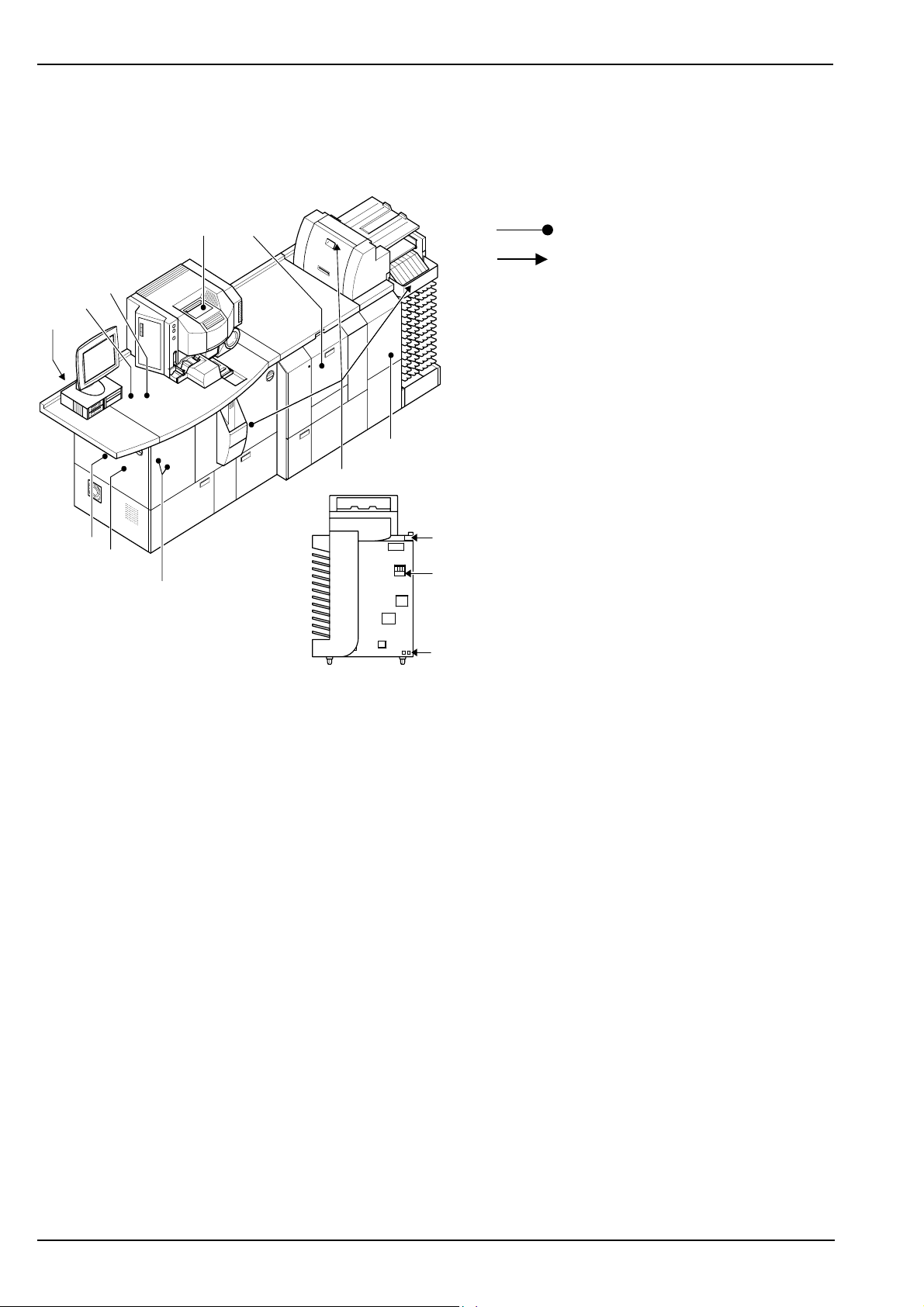
Introduction d-lab.2, d-lab.2plus, netlab.2plus: Operation
d-lab.2plus with solid state laser
d-lab.2plus select Type 8060/813 and Type 8060/814
d-lab.2plus basic Type 8060/271 and Type 8060/273
d-lab.2plus (70mm) Type 8060/158 + 8060/255
Legend:
89, 10
Label inside
Label outside
2
1
11
6, 7
5
3
G_GG101_4f
15
2
14
4
12, 13
1-16 2005-05-01 / PN 04092_01 AgfaPhoto
Page 31

d-lab.2, d-lab.2plus, netlab.2plus: Operation Introduction
1
netlab.2plus with solid state laser (Typ 8060/505)
Legend:
8
Label inside
Label outside
2
1
11
6, 7
5
3
2
G_GG101_4fb
15
14
4
12, 13
AgfaPhoto 2005-05-01 / PN 04092_01 1-17
Page 32

Introduction d-lab.2, d-lab.2plus, netlab.2plus: Operation
No. Label Meaning
This label warns the user from exposure to laser radiation. It
gives the technical specifications of the laser used in the
machine (output intensity, wavelength, and laser class).
1
G_SH202
This label warns the user about opening the laser module and
exposure to laser radiation.
The laser beam which may escape from the open laser module
can be dangerous for the eyes.
2
G_SH201
1-18 2005-05-01 / PN 04092_01 AgfaPhoto
Page 33

d-lab.2, d-lab.2plus, netlab.2plus: Operation Introduction
No. Label Meaning
1
Machines with gas laser:
d-lab.2 Type 8060/260
d-lab.2plus Type 8060/261
G_SH204g
Machines with solid state laser:
d-lab.2 select
Type 8060/803 and Type 8060/804
d-lab.2 basic
Type 8060/270 and Type 8060/272
3
d-lab.2 (70mm)
Type 8060/157 + 8060/255
d-lab.2plus select
Type 8060/813 and Type 8060/814
This label warns the user not to look into the laser beam.
Laser class as well wavelength and power of the laser radiation
are specified.
d-lab.2plus basic
Type 8060/271 and Type 8060/273
d-lab.2plus (70mm)
Type 8060/158 + 8060/255
netlab.2plus basic
Type 8060/505
G_SH204f
This label warns the user about opening the laser module and
4
G_SH203
thus lose the adjustment.
The laser module is a pre-adjusted unit. Once the laser module
is out of adjustment, the machine is out of order.
AgfaPhoto 2005-05-01 / PN 04092_01 1-19
Page 34

Introduction d-lab.2, d-lab.2plus, netlab.2plus: Operation
No. Label Meaning
This label warns the user about the risk of injuries by rotating
components (pulling, squeezing).
5
G_SH205
Do not touch these components when the machine is on and
keep the door closed.
This label indicates that the dryer assembly is hot during
operation and must not be touched before it has cooled down.
6
G_SH211
This label indicates that the dryer assembly is quite heavy. Do
not drop it on your feet. Watch your fingers during removal and
installation to avoid squeezing and bruising.
7
8
9
G_SH212
This label warns the user about sharp blade which may cut the
user when touched.
Do not reach into the cutting unit during operation. Do not
touch the cutting blades either when the machine is off.
G_SH206
This label indicates that the scanner lamp gets very hot during
operation and must not be touched before it has cooled down.
Risk of burning!
G_SH213
1-20 2005-05-01 / PN 04092_01 AgfaPhoto
Page 35

d-lab.2, d-lab.2plus, netlab.2plus: Operation Introduction
No. Label Meaning
This label indicates that the lamp switch must not be pressed
if the scanner lamp is not in operating position. Nonobservance may result in damage or even destruction of the
exposure filters.
10
G_SH214
Type label with CE certification
The type of the minilab is listed as the type number:
Machines with gas laser:
d-lab.2 Type 8060/260
d-lab.2plus Type 8060/261
Machines with solid state laser:
G_SH_TYP260 (d-lab.2)
11
d-lab.2 select Type 8060/803 and Type 8060/804
d-lab.2 basic Type 8060/270 and Type 8060/272
d-lab.2 (70mm) Type 8060/157 + 8060/255
d-lab.2plus select Type 8060/813 and Type 8060/814
d-lab.2plus basic Type 8060/271 and Type 8060/273
d-lab.2plus (70mm) Type 8060/158 + 8060/255
1
netlab.2plus basic Type 8060/505
The CE certification means that the machine is in compliance
with all applying EC Regulations.
The given voltage-, fuse- and frequency values for single-phase
and three-phase connections are listed.
This label informs the user to read the installation instructions
before connecting the machine to power.
12
G_SH208
Installation errors may result in personal injuries by electric
shock or in machine damage when the machine is connected
to power.
This label warns the user about the risk of injuries by electric
shock in case of open covers.
13
G_SH210
This label identifies the main switch or main breaker.
14
G_SH209
AgfaPhoto 2005-05-01 / PN 04092_01 1-21
Page 36

Introduction d-lab.2, d-lab.2plus, netlab.2plus: Operation
No. Label Meaning
This label refers to the Operating Instructions (this
documentation) regarding the type plate position (see position
11).
15
1.7 Transport, Installation, First Operation
Transport, installation, as well as first operation should be organized and handled by an
AgfaPhoto authorized Service Technician.
See separate “Installation“ instructions for detailed information for individual subjects.
1.8 Storage
1.8.1 Chemicals
Chemicals should be stored and prepared according to the manufacturer’s information
and advice.
1.8.2 Photographic Paper
All photographic papers must always be stored in a cool and dry place.
The best storage temperature is between +2 ºC and +10 ºC.
Opened packages have to be stored at a relative humidity of 50-60%.
Storage at 20 ºC for several days is possible without any problems.
Storage temperatures above 30 ºC should be avoided as they will cause visible changes
after only a few days.
■
1-22 2005-05-01 / PN 04092_01 AgfaPhoto
Page 37

d-lab.2, d-lab.2plus, netlab.2plus: Operation General Description, Work Routines and Operation
2 General Description, Work Routines and Operation
2.1
General Description......................................................................................................................................................2-1
2.2 Product Description......................................................................................................................................................2-7
2.2.1 Corresponding Film Types and Images .............................................................................................2-7
2.2.2 Image Editing..............................................................................................................................................2-7
2.3 Operation Routines.......................................................................................................................................................2-8
2.3.1 Drive Bay
Applies only to d-lab.2plus, netlab.2plus................................................................................................2-8
2.3.2 Scanner
Applies only to d-lab.2/2plus ....................................................................................................................2-9
2.3.3 Main computer ........................................................................................................................................2-10
2.3.4 Printer .........................................................................................................................................................2-11
2.3.5 Paper Processor.......................................................................................................................................2-12
2.3.6 Sorter...........................................................................................................................................................2-13
2.3.7 Densitometer ...........................................................................................................................................2-14
2.4 Controls on the Minilab...........................................................................................................................................2-15
2.4.1 Keys and Pilot Lamps............................................................................................................................2-15
2.4.2 Touchscreen Monitor ............................................................................................................................2-16
2.4.3 Main Breaker and Ground Fault Interrupter .................................................................................2-17
2.5 Switching the Machine On and Off .....................................................................................................................2-18
2.5.1 Preparations Prior to Switch-on ........................................................................................................2-18
2.5.2 Automatic Switch-On (Timer).............................................................................................................2-18
2.5.3 Switching On with the ON Key .........................................................................................................2-19
2.5.4 Switching the Machine On and Off with the Main Breaker ...................................................2-20
2.5.5 System Start .............................................................................................................................................2-22
2.5.6 User Login..................................................................................................................................................2-22
2.5.7 The Start Screen...................................................................................................................................... 2-23
2.5.8 Log-in of Another User..........................................................................................................................2-24
2.5.9 End of Work and Shutdown ................................................................................................................2-24
2.5.9.1 Sleep Mode...................................................................................................................................2-25
2.5.9.2 Switching the Machine Off.....................................................................................................2-25
2.6 Screen Layout and Controls on the Screen ......................................................................................................2-27
2.6.1 Information Area.....................................................................................................................................2-28
2.6.2 Buttons .......................................................................................................................................................2-30
2.6.3 Pulldown Menus .....................................................................................................................................2-31
2.6.4 Popup Windows ......................................................................................................................................2-32
2.6.5 Input Screens ........................................................................................................................................... 2-34
2.6.5.1 Entering Text................................................................................................................................2-34
2.6.5.2 Entering Numbers ...................................................................................................................... 2-35
2.6.6 Reorder Keyboard
Applies only to d-lab.2/2plus
2.7 Main Menus..................................................................................................................................................................2-38
2.8 Calling Up Info ............................................................................................................................................................ 2-43
2.8.1 Film Drive Info
Applies only to d-lab.2/2plus
2.8.2 Printer Info ................................................................................................................................................2-46
2.8.3 Paper Processor Info..............................................................................................................................2-47
2.8.4 Order Info...................................................................................................................................................2-48
2.8.5 Version Info...............................................................................................................................................2-49
2.8.6 Displaying the Error List.......................................................................................................................2-50
.................................................................................................................2-36
.................................................................................................................2-45
2
AgfaPhoto 2005-05-01 / PN 04092_01 2-i
Page 38

General Description, Work Routines and Operation d-lab.2, d-lab.2plus, netlab.2plus: Operation
2.9 Activating Help ........................................................................................................................................................... 2-51
2.10 Ejecting the ZIP ..........................................................................................................................................................2-53
■
2-ii 2005-05-01 / PN 04092_01 AgfaPhoto
Page 39

d-lab.2, d-lab.2plus, netlab.2plus: Operation General Description, Work Routines and Operation
2.1 General Description
Applies to d-lab.2
1
2
2
The d-lab.2 comprises of four main components:
1 Main Computer
(separate, but integrated in the scanner
housing), controls the general work process
and generates the image exposure data.
The monitor (touchscreen) for the operation of
the machine is connected on the main
computer.
2 Scanner
digitizes the negatives and slides and
transmits corrections and exposure values.
3 Printer
prepares the paper and transports it to the
print engine (PE) and to the Paper Processor.
The integrated laser exposes the paper, the
back printer provides for the printing of
various data on the back of the paper.
4 Paper Processor with Dryer and Sorter
develops and dries the paper and stacks the
finished prints in the connected sorter or on
the tray for large print formats.
3
4
G_GG204
AgfaPhoto 2005-05-01 / PN 04092_01 2-1
Page 40

General Description, Work Routines and Operation d-lab.2, d-lab.2plus, netlab.2plus: Operation
9
10
8
6
11
5
3
2
12
7
4
22
1
G_GG201_2 (Fig. shows d-lab.2)
21
1 Door to power supplies
2 Touchscreen
3 Main computer
4 Film feeder with a cleaning brush
5 Scanner lamp and filter wheel
6 Film take-up
7 Film carrier
8 Wet section with racks, crossovers, chemical filters
9 Paper outlet (PO) with integrated densitometer
10 Tray for large print formats
11 Main breaker
12 Order sorter
13 Dryer
20
13
14
15
16
17
18
19
14 Right hand door on the Paper Processor (snap lock),
central water tank, shut-off taps / filter for water and
ASTOR tank
15 Lower panel of the Paper Processor; replenisher tanks
16 Docking station
17 Lower left hand door on the Paper Processor; drain taps
for chemicals (machine tanks) and overflow tanks
18 Printer front door; lens / CCD, transport unit (TU), lane
distributor (LD) with chemical control strip box
19 Door for right hand paper magazine
20 Film collecting box
21 Door for left hand paper magazine
22 Printer side door; print engine (PE) and laser module
2-2 2005-05-01 / PN 04092_01 AgfaPhoto
Page 41

d-lab.2, d-lab.2plus, netlab.2plus: Operation General Description, Work Routines and Operation
Applies to d-lab.2plus
The d-lab.2plus comprises of four main
components:
1
1 Main Computer
2
(separate, but integrated in the scanner
housing), controls the general work process
and generates the image exposure data.
The monitor (touchscreen) for operation of
machine and drive bay for loading digital
image files of different storage media are
connected on the main processor.
2 Scanner
digitizes the negatives and slides and
transmits corrections and exposure values.
2
3 Printer
prepares the paper and transports it to the
print machine (PM) and to the Paper
Processor. The integrated laser exposes the
paper, the back printer provides for the
printing of various data on the back of the
paper.
4 Paper Processor with Dryer and Sorter
develops and dries the paper and stacks the
finished prints in the connected sorter or on
the tray for large print formats.
3
4
G_GG104
AgfaPhoto 2005-05-01 / PN 04092_01 2-3
Page 42

General Description, Work Routines and Operation d-lab.2, d-lab.2plus, netlab.2plus: Operation
9
10
8
6
11
5
3
2
1
7
12
4
13
14
15
16
17
22
G_GG101_2 (Fig. shows d-lab.2plus)
21
1 Drive bay
2 Touchscreen
3 Main computer
4 Film feeder with a cleaning brush
5 Scanner lamp and filter wheel
6 Film take-up
7 Film carrier
8 Wet section with racks, crossovers, chemical filters
9 Paper outlet (PO) with integrated densitometer
10 Tray for large print formats
11 Main breaker
12 Order sorter
13 Dryer
20
18
19
14 Right hand door on the Paper Processor (snap lock),
central water tank, shut-off taps / filter for water and
ASTOR tank
15 Lower panel of the Paper Processor; replenisher tanks
16 Docking station
17 Lower left hand door on the Paper Processor; drain taps
for chemicals (machine tanks) and overflow tanks
18 Printer front door; lens / CCD, feeder unit (FU), sheet
distributor (SD) with chemical control strip box
19 Door for right hand paper magazine
20 Film collecting box
21 Door for left hand paper magazine
22 Printer side door; print machine (PM) and laser module
23 Door to power supplies
2-4 2005-05-01 / PN 04092_01 AgfaPhoto
Page 43

d-lab.2, d-lab.2plus, netlab.2plus: Operation General Description, Work Routines and Operation
Applies to netlab.2plus
The netlab.2plus comprises of three main
components:
1
1 Main Computer
2
controls the general work process and
generates the image exposure data.
The monitor (touchscreen) for operation of
machine and drive bay for loading digital
image files of different storage media are
connected on the main processor.
2 Printer
prepares the paper and transports it to the
print machine (PM) and to the Paper
Processor. The integrated laser exposes the
2
paper, the back printer provides for the
printing of various data on the back of the
paper.
3 Paper Processor with Dryer and Sorter
develops and dries the paper and stacks the
finished prints in the connected sorter or on
the tray for large print formats.
3
G_GG104b
AgfaPhoto 2005-05-01 / PN 04092_01 2-5
Page 44

General Description, Work Routines and Operation d-lab.2, d-lab.2plus, netlab.2plus: Operation
5
6
4
7
3
2
1
8
9
10
11
12
13
17
18
G_GG101b _2 (Fig. shows netlab.2plus)
16
1 Drive bay
2 Touchscreen
3 Main computer
4 Wet section with racks, crossovers, chemical filters
5 Paper outlet (PO) with integrated densitometer
6 Tray for large print formats
7 Main breaker
8 Order sorter
9 Dryer
10 Right hand door on the Paper Processor (snap lock), central
water tank, shut-off taps / filter for water and ASTOR tank
14
15
11 Lower panel of the Paper Processor; replenisher tanks
12 Docking station
13 Lower left hand door on the Paper Processor; drain taps
for chemicals (machine tanks) and overflow tanks
14 Printer front door; feeder unit (FU), sheet distributor (SD)
with chemical control strip box
15 Door for right hand paper magazine
16 Door for left hand paper magazine
17 Printer side door; print machine (PM) and laser module
18 Door to power supplies
2-6 2005-05-01 / PN 04092_01 AgfaPhoto
Page 45

d-lab.2, d-lab.2plus, netlab.2plus: Operation General Description, Work Routines and Operation
2.2 Product Description
2.2.1 Corresponding Film Types and Images
The following film types and images can be printed quickly and simply on a Minilab:
d-lab.2/2plus:
netlab.2plus: – Digital images of the formats: ".jpg" (also JPEG2000 and progressive
Digital images can be transmitted to Minilab via the following means:
– via storage media: diskette, Zip, CD-ROM/DVD or memory cards (PCMCIA, Compact
Flash, SmartMedia, Memory Stick, SD/MMC memory card)
– via network (Workstation)
Note
The customer is responsible for the organization of network and/or workstations and
for the connection.
– Black/white and color negative films, formats 135, 120, 110, APS;
APS only color negative films
– Black/white and Color slides (mounted, 5 x 5 cm)
– Reversal film strips, formats 135, 120/220, Black/white and Color
(optional)
– Digital images of the formats: ".jpg" (also JPEG2000 and progressive
compression), ".bmp" or ".tif" (also with LZW compression)
compression), ".bmp" or ".tif" (also with LZW compression)
2
2.2.2 Image Editing
Apart from this, the Minilab offers a great variety of image editing options:
– Color and density corrections
– Cropping
– Image improvement:
– Area contrast, detail contrast
– Sharpness
– Saturation
– Special: colored text and borders
– Red eye correction (option)
All modifications are calculated in the main computer. The image on the screen is
refreshed immediately (does not apply to red eye correction).
AgfaPhoto 2005-05-01 / PN 04092_01 2-7
Page 46

General Description, Work Routines and Operation d-lab.2, d-lab.2plus, netlab.2plus: Operation
2.3 Operation Routines
The operator enters the required settings and inserts a film or slide or loads the image
data to be printed.
The Minilab then activates the following routines:
– Applies only to d-lab.2/2plus
Scanning of the image (prescan and mainscan, for negatives and slides; not required
for digital images)
– Image editing, if requested
– Calculation of the exposure data
– Paper cutting
– Paper transport
– Paper exposure
– Distribution of the paper to the tracks of the Paper Processor
– Paper development
– Paper drying
– Paper stacking in the sorter or on the tray for large print formats
2.3.1 Drive Bay
Applies only to d-lab.2plus, netlab.2plus
G-GG133
The drive bay includes several drives for the loading of digital files from storage media:
– Zip diskette
– CD-ROM/DVD
– Memory cards (PCMCIA, Compact Flash/MicroDrive, Smart Media, Memory Stick, SD
MMC memory card)
2-8 2005-05-01 / PN 04092_01 AgfaPhoto
Page 47

d-lab.2, d-lab.2plus, netlab.2plus: Operation General Description, Work Routines and Operation
2.3.2 Scanner
Applies only to d-lab.2/2plus
After making all necessary settings for a the print order the operator inserts the film
through the film feeder into the negative carrier.
1 Lamp 4 Film drive
2 Exposure filters 5 Lens
3 Mirror box 6 CCD area
2
dalbr133
While the film is transported through the negative carrier and into the film takeup, the
prescanner determines the exposure data for each negative of the film (prescan).
After the main computer has calculated the correction data, the negatives are digitized:
The film is pulled out of the film takeup and the negatives are positioned one by one in
the negative carrier and exposed. Three color separations per negative are exposed on the
CCD by means of the color filter wheel (mainscan; approx. 2,000 x 3,000 pixels). A fourth
exposure with infrared light is used for the scratch correction.
The processing of slides is similar with the following differences:
– Mounted slides are individually inserted via slide carrier, reversal film strips are
inserted via the film carrier of the corresponding size negative film (135, 120/220).
– The color filters used for slide scanning are different from the negative filters.
Slides are automatically detected
– in case of mounted slides when the slide carrier is mounted,
– and in case of reversal film strips when the print mode Slide (see
with slide print mode
in Chapter 6) is selected.
Working
In both cases the minilab automatically switches to the slide filters.
Note
The slide carrier for mounted slides and slide filters are available as an option.
AgfaPhoto 2005-05-01 / PN 04092_01 2-9
Page 48

General Description, Work Routines and Operation d-lab.2, d-lab.2plus, netlab.2plus: Operation
2.3.3 Main computer
G_GG212_1 (Fig. shows d-lab.2)
1
G_PC713_1 (Fig. shows netlab.2plus)
The main computer calculates exposure data for the image based on digitized image data
and prescan data (of negative films and slides; only d-lab.2/2plus) and image data (digital
images), as well as corrections, if applicable, and sends this data to the Printer.
2-10 2005-05-01 / PN 04092_01 AgfaPhoto
Page 49

d-lab.2, d-lab.2plus, netlab.2plus: Operation General Description, Work Routines and Operation
2.3.4 Printer
Applies to d-lab.2
1 Paper magazine left (8 inch magazines)
2 Paper magazine right (12 inch magazines)
3 Sheet gear (SG)
4 Single sheet buffer (SR)
5 Sheet bridge (SB)
6 Transport unit (TU)
7 Print engine (PE)
8 Laser
9 Lane distributor (LD)
10 Sheet transfer (ST)
Applies to d-lab.2plus/netlab.2plus
1 Paper magazine left (12 inch magazines)
2 Paper magazine right (12 inch magazines)
3 Switching Gear (SG)
4 Sheet Stocker (SR)
5 Sheet Bridge (SB)
6 Feeder Unit (FU)
7 Print Machine (PM)
8 Laser
9 Sheet Distributor (SD)
10 Sheet Transfer (ST)
6
8
7
G_GG209 (Fig. shows d-lab.2)
6
10
9
5
3
2
1
4
10
2
9
5
3
8
7
G_GG109e (Fig. shows netlab.2plus)
4
2
1
The Printer cuts the paper and transports it to the exposure station (print engine or print
machine, 7), there the laser beam exposes the paper, which then continues through the
transport section (transport unit or feeder unit, 6) to the lane or sheet distributor (9). There
the back print is applied.
The lane or sheet distributor (9) distributes the prints on the tracks of the Paper Processor.
AgfaPhoto 2005-05-01 / PN 04092_01 2-11
Page 50

General Description, Work Routines and Operation d-lab.2, d-lab.2plus, netlab.2plus: Operation
2.3.5 Paper Processor
1
2
G-GG702 (Fig. shows d-lab.2)
The exposed paper runs through the machine tanks (1) of the Paper Processor, which
contain the chemical solutions developer (DEV), bleach-fix (BX), and stabilizer (STB), and
afterwards through the dryer (2).
2-12 2005-05-01 / PN 04092_01 AgfaPhoto
Page 51

d-lab.2, d-lab.2plus, netlab.2plus: Operation General Description, Work Routines and Operation
2.3.6 Sorter
3
1
2
2
G_GG214 (Fig. shows d-lab.2)
After drying, the prints up to a certain size (see below) exit via the print chute (1) into the
sorter (2) where they are sorted by orders and stacked in buckets. Larger prints are put on
the tray for large prints formats (3).
Maximum sizes for deposit in sorter buckets:
10“ Sorter: prints up to 254 mm (10") in length
6“ Sorter: prints up to 152 mm (6") in length
Special cases:
– If an order exceeds the capacity of a bucket (55 prints for sizes up to 13x18 cm (5x7"),
43 prints for sizes bigger than 13x18 cm), the sorter moves on to the next bucket, i.e.
the prints of one order may be in two or more buckets.
– Splices in the paper rolls are cut separately and the respective pieces of paper are
deposited in the print order stack.
AgfaPhoto 2005-05-01 / PN 04092_01 2-13
Page 52

General Description, Work Routines and Operation d-lab.2, d-lab.2plus, netlab.2plus: Operation
Splices in paper rolls
Note
For technical reasons some of the paper rolls come with splices. In compliance with
ISO 1009 the maximum number of splices in a roll length of
– 79 / 91,5 m: 1 splice
– 158 / 183 m: 2 splices
This information applies to Sensatis (Splendix) paper. The relations for other papers are
similar. Only lengths used in the d-lab family are listed here.
To compensate for the paper loss due to splices 30 cm of paper are added per splice. In
AGFACOLOR paper rolls the splices are marked with oblong holes which initiates the
required blank paper transports in the Printer.
2.3.7 Densitometer
1
G_GG116 (Fig. shows d-lab.2plus)
The densitometer (1), installed above the dryer, is used for automatic machine and paper
calibration. For this purpose it measures the MBL and PBL tests printed in the machine
(see
Tests
, Chapter 5).
2-14 2005-05-01 / PN 04092_01 AgfaPhoto
Page 53

d-lab.2, d-lab.2plus, netlab.2plus: Operation General Description, Work Routines and Operation
2.4 Controls on the Minilab
2.4.1 Keys and Pilot Lamps
1
2
3
G-GG212_2 (Fig. shows d-lab.2)
Applies to d-lab.2/2plus
1 ON key
2 Timer lamp
3 STOP key (film stop key))
Applies to netlab.2plus
1 ON key
2 Timer lamp
2
1
2
G-PC713_2 (Fig. shows netlab.2plus)
ON key (1)
If the machine is shut down by the menu command End of work > Shutdown, it remains
in timer mode until the next automatic startup. If you want to work before the timer starts
the machine again automatically, press the ON key to switch on (see
Switching the Machine Off
in this chapter, as well as
Setting the Timer
End of Work and
in Chapter 4).
Furthermore the ON key can be used for a reset while the machine is running (see
Reset via the ON key
in Chapter 7).
Timer lamp (2)
The timer lamp lights up if the machine is in timer mode after shutdown via End of
work > Shutdown.
STOP key (film stop 3; only d-lab.2/2plus))
If a film jam occurs or you assume a film jam, you can press the film stop key to stop the
scanner immediately. Film scanning stops, the order is canceled, and the machine is
reset. The reset popup is shown on the screen with the button Yes. Press this button only
if there is no more paper in the Printer (otherwise this may cause a paper jam).
See
Problems During Scanning
in Chapter 7.
AgfaPhoto 2005-05-01 / PN 04092_01 2-15
Page 54

General Description, Work Routines and Operation d-lab.2, d-lab.2plus, netlab.2plus: Operation
2.4.2 Touchscreen Monitor
G_GG113
The operation of the Minilab is menu-supported via touchscreen monitor. All functions
are activated by pressing the touch-sensitive buttons
(See
Screen Layout and Controls on the Screen
on the screen.
in this Chapter.)
Specifications:
– 15 inch screen
– SVGA resolution 1,024 x 768 pixels
– Screen-refresh frequency > 75 Hz
The customer can choose between an LCD Monitor (flat panel monitor, type 8060/341)
and a CRT Monitor (type 8060/340; see
Ordering Aid
in the Pre-Installation section of
the Service Manual).
2-16 2005-05-01 / PN 04092_01 AgfaPhoto
Page 55

d-lab.2, d-lab.2plus, netlab.2plus: Operation General Description, Work Routines and Operation
2.4.3 Main Breaker and Ground Fault Interrupter
1
2
2
G_GG220 (Fig. shows d-lab.2)
Main breaker (1) and ground fault interrupter (2) are located on the side of the Minilab
next to the sorter.
Both switches remain always on for normal operation of the Minilab. The main breaker
must only be switched off
– for some maintenance work (see
– for various routines when changing the chemicals (see
Maintenance
, Chapter 8),
Changing Chemicals
,
Chapter 3),
– for complete shutdown of the machine (see
Machine Shutdown
, Chapter 11).
The ground fault interrupter (GFI) remains always on.
AgfaPhoto 2005-05-01 / PN 04092_01 2-17
Page 56

General Description, Work Routines and Operation d-lab.2, d-lab.2plus, netlab.2plus: Operation
2.5 Switching the Machine On and Off
There are several ways to switch on the Minilab:
– automatically via the integrated timer:
The machine switches on automatically at the set time (see
Setting the Timer
in
Chapter 4) (standard method).
– manually via the ON key (if the machine is off and in timer mode)
– manually via the main breaker (if the machine was switched off via the main breaker)
The machine can be switched off:
– manually via End of work > Shutdown; the machine is then in timer mode (standard
method)
– automatically, if no inputs are made within an adjustable time after switching on
(included for incorrect timer settings, e.g. startup on holidays; the automatic switch-off
function is disabled as soon as an input is made after switch-on).
– manually via the main breaker (exception; only in emergencies or if required for
operational reasons; see
Switching the Machine On and OFF with the Main Breaker
in this chapter)
2.5.1 Preparations Prior to Switch-on
– Insert loaded paper magazines.
– Only applies to d-lab.2/2plus
Insert film carrier and mount the matching mirror box.
Otherwise the machine cannot start up correctly, and an error message may be displayed.
2.5.2 Automatic Switch-On (Timer)
The Minilab starts automatically at certain times if
– these staring times have been defined in the timer settings (see
in Chapter 4),
– the machine has been switched off via End of work > Shutdown (see
and Shutdown
– the main breaker has not been switched off.
in this chapter),
Setting the Timer
End of work
2-18 2005-05-01 / PN 04092_01 AgfaPhoto
Page 57

d-lab.2, d-lab.2plus, netlab.2plus: Operation General Description, Work Routines and Operation
2.5.3 Switching On with the ON Key
1
G_GG212_3 (Fig. shows d-lab.2)
If the machine is switched off and if it is in timer
mode (see
Setting the Timer
in Chapter 4), it
can be switched on with the ON key:
Press the ON key (1).
2
G_PC713_3 (Fig. shows netlab.2plus)
1
AgfaPhoto 2005-05-01 / PN 04092_01 2-19
Page 58

General Description, Work Routines and Operation d-lab.2, d-lab.2plus, netlab.2plus: Operation
2.5.4 Switching the Machine On and Off with the Main Breaker
CAUTION!
Only use the main breaker in emergencies to switch off the machine.
In normal operation always use the routine End of work > Shutdown to switch
off the machine (see
off the main breaker (1)!
If for technical reasons it is necessary to switch off the machine completely, e.g. for
longer down times (see Chapter 11), for some maintenance routines (see Chapter 8)
or for changing the chemicals (see
machine first as described in
off the main breaker.
If the machine is switched off with the main breaker without shutdown, this may
– (applies only to d-lab.2 with gas laser, Type 8060/260 and d-lab.2plus with gas laser, Type
8060/261)
reduce the service life of the blue/green laser considerably (failure of after-cooling).
– cause problems with the main computer; the operating system may have to be
reinstalled,
– cause paper jams if not all prints have left the Paper Processor.
If the machine was switched off via the main breaker wait at least one minute before you
switch on again. Otherwise the hard disc of the main computer may get damaged.
End of Work and Shutdown
Changing chemicals
End of Work and Shutdown
in this chapter); do not switch
in Chapter 3), shut down the
in this chapter, and then switch
2-20 2005-05-01 / PN 04092_01 AgfaPhoto
Page 59

d-lab.2, d-lab.2plus, netlab.2plus: Operation General Description, Work Routines and Operation
Switch on the machine:
Switch on the main breaker (1)
Switch off the machine:
Shut down the machine as described in
of Work and Shutdown
Do not switch off the main breaker (1).
The ground fault interrupter (2) remains
always on.
1
2
in this chapter.
End
2
G_GG220 (Fig. shows d-lab.2)
AgfaPhoto 2005-05-01 / PN 04092_01 2-21
Page 60

General Description, Work Routines and Operation d-lab.2, d-lab.2plus, netlab.2plus: Operation
2.5.5 System Start
After manual or automatic switch-on the chemical solutions and the dryer are heated up.
During this phase various windows screen pop up on the screen; they indicate:
– progress of warm-up (actual and nominal temperatures of solutions and dryer)
– remaining time until the individual modules are ready for operation
– various information about the progress of the machine initialization
– error messages, if applicable
(see Chapter 7,
Troubleshooting
, for remedies for occurring errors)
The machine is ready for operation after the chemical solutions and the dryer have
reached the nominal temperatures.
2.5.6 User Login
If a standard user with automatic login has been defined in the machine settings
(see
warm-up the start screen is displayed (see next section
Otherwise the Login screen is displayed.
If an operator, who has to enter his or her Password, has been defined as standard user in
the machine settings, the name is already shown but the password must still be entered.
If no operator has been entered as standard user in the machine settings, the user name
must be selected and the password must be entered:
Defining a Standard User
in Chapter 4), user login is not necessary here: After the
Start Screen
).
Select user name if necessary
Type the password if necessary
The start screen will be displayed.
2-22 2005-05-01 / PN 04092_01 AgfaPhoto
Page 61

d-lab.2, d-lab.2plus, netlab.2plus: Operation General Description, Work Routines and Operation
2.5.7 The Start Screen
m0
After automatic or manual login of a user the start screen is displayed. A menu bar with
five main menus is displayed along the lower edge (see
Main Menus
in this chapter).
2
AgfaPhoto 2005-05-01 / PN 04092_01 2-23
Page 62

General Description, Work Routines and Operation d-lab.2, d-lab.2plus, netlab.2plus: Operation
2.5.8 Log-in of Another User
072
Press End of work in the menu bar.
Press Change user.
The Change user login screen is displayed.
Press Logout.
The present user is logged out.
Note:
After Logout was pressed the machine can
only be operated again with login of a user. By
this function the machine can be protected
form unauthorized use, e.g. during breaks.
Press the name of the respective user in the
list of names (use the arrow keys to scroll, if
necessary).
Press Password and type the password (four
characters).
Press Login:
If the new user has another language
assigned in the machine settings, all texts
will now be displayed in this language (see
Defining Users and Assigning Rights
Chapter 4).
in
2.5.9 End of Work and Shutdown
Depending on the set-up in machine settings, the machine can be
– completely switched off or
– partly switched off (set to sleep mode) via menu command (see
below
).
Note
The Minilab switches off automatically if no further entries were made within an
adjustable time after startup (see
Setting the Timer
in Chapter 4).
2-24 2005-05-01 / PN 04092_01 AgfaPhoto
Page 63

d-lab.2, d-lab.2plus, netlab.2plus: Operation General Description, Work Routines and Operation
2.5.9.1 Sleep Mode
In sleep mode scanner, Printer and Paper Processor are switched off, the main computer
remains on for the set time. This allows e.g. checking of statistics (on site or via remote
access).
2
The sleep mode can be activated for any weekdays as desired (see
Chapter 4).
2.5.9.2 Switching the Machine Off
Setting the Timer
in
Note
Applies only to d-lab.2/2plus
Any negative carrier may be in the machine
when it is switched off.
Press End of work in the menu bar.
Press Shutdown.
The Shutdown screen opens.
The preset settings for the next automatic switch-on (date, time) for this day are shown on
the top right, and for switch-off top left (see
(Timer)
in Chapter 4).
Setting startup and shutdown times
If the displayed settings should not be valid
for the next automatic switch-on (startup):
041
Press Change Timer.
In the following screen enter date and
time for the next start, if necessary
switch the timer on or off and confirm
with OK.
Press Next Login.
Select the user for the next login from
the listing.
If the sleep mode should be deactivated for the
next automatic switch-off:
Press Sleep mode
Note
The time for the automatic shutdown cannot
be changed here. If the Sleep mode has been
activated in the presettings, it cannot be
activated here.
These settings can be changed in the Startup
settings screen (press the buttons Settings >
Machine settings > Startup; see
startup and shutdown times (Timer)
Chapter 4).
Setting
in
AgfaPhoto 2005-05-01 / PN 04092_01 2-25
Page 64

General Description, Work Routines and Operation d-lab.2, d-lab.2plus, netlab.2plus: Operation
Note
These modifications apply to the next start
only. Permanent modifications can be made
via the machine settings (see
Timer
in Chapter 4).
If the sleep mode is activated, the Minilab is shut down but the main computer remains
on until the set switch-off time. The switch-off time for the main computer is displayed.
If any prompts come up, answer them:
Applies only to d-lab.2/2plus
In case of unfinished APS orders answer the
query whether they should be saved. Orders
that are not saved are lost.
In case of orders that are not priced confirm
the warning messages. Finished orders will
also be saved if they have not been priced.
Performing daily maintenance
(see
8 and refer to the note below).
Press OK.
Daily Maintenance Work
Setting the
in Chapter
If the sleep mode has not been activated, the Minilab will be shut down and switched off.
CAUTION!
Do not switch off the machine with the main breaker (see
Machine On and Off with the Main Breaker
in this chapter).
Switching the
Note
To avoid problems during the next startup we
recommend the following procedure:
After switching off
check if there is enough water in the
water tank.
check the effluent tanks and empty
them if necessary.
2-26 2005-05-01 / PN 04092_01 AgfaPhoto
Page 65

d-lab.2, d-lab.2plus, netlab.2plus: Operation General Description, Work Routines and Operation
2.6 Screen Layout and Controls on the Screen
2
046a
The screen is divided into different areas:
Information area (1):
This includes:
– (1-1) the area for messages
– (1-2) the buttons i, ?, Stop
– (1-3) the status bar
Active screen (2):
Depending on the function that has been called up, the screen shows buttons, image
views and/or information blocks.
Menu bar with five main menus (3)
Note
The term button in these instructions refers to the touch-sensitive field on the
touchscreen. Pressing on the buttons starts the respective function.
AgfaPhoto 2005-05-01 / PN 04092_01 2-27
Page 66

General Description, Work Routines and Operation d-lab.2, d-lab.2plus, netlab.2plus: Operation
The areas (1) and (3) are displayed in every screen; the menu bar (3), however, is disabled
in some work situations (e.g. if a problem occurred which must be solved before work can
be continued).
Note
Only one screen is active at a time; it is not possible to open several screens at the
same time.
2.6.1 Information Area
infobar
The information area includes several buttons, the status bar, and a message area.
Buttons:
Displays the Status information screen
Displays context related help function for all screens and error messages (see
Up Help
If the machine no longer reacts to operator inputs, a software reset can be initiated via
this button (see
The buttons
be reached any time.
in this chapter).
Reset With the Stop Button
i, ?, Stop are always accessible during operation. Info and help screens can
(see
in Chapter 7).
Calling Up Info
in this chapter).
Calling
2-28 2005-05-01 / PN 04092_01 AgfaPhoto
Page 67

d-lab.2, d-lab.2plus, netlab.2plus: Operation General Description, Work Routines and Operation
paperinfo1
paperinfo2
The status bar shows:
– Name of the current screen.
– Remaining length, width, and surface of the paper in the inserted magazines
– Information if the same laser point has been adjusted for both papers or if they are
different (see
Copying of laser points for calibration of a paper configuration
in
Chapter 5). If the same laser point is adjusted for both papers an equal sign is
displayed in the paper roll symbol
– Date and time
The message area displays:
– Information, warnings, requests
– Error messages
Note
All information, warnings, prompts, and error messages are saved in the error listing.
Access to the error listing is provided by pressing the buttons i and Error list (see
section
Error List Display
in this chapter).
2
Depending on the type of message ist appearance may have different consequences:
− The operator can continue working without confirmation or action.
− An error must be repaired before working can be continued
(see
Troubleshooting
, Chapter 7).
− Some messages can be ignored several times until the machine forces the operator to
react.
AgfaPhoto 2005-05-01 / PN 04092_01 2-29
Page 68

General Description, Work Routines and Operation d-lab.2, d-lab.2plus, netlab.2plus: Operation
2.6.2 Buttons
Depending on the type of button pressing them starts the following actions:
i, ? and Stop
see above, section
in the menu bar: call up the submenu
others: to start, interrupt or stop an action
open the pulldown menu (see below,
open the input screen to enter texts or numbers (see below,
switching on or off, or
activating or deactivating a function
scrolling through the pulldown menus
– entries selected in a pulldown menu can be shifted to another menu (select
entry/press, then press arrow button)
Information Area
Pulldown Menus
)
Input Screens
)
– The sequence of entries in a pulldown menu can be changed (select entry/press and
move it up or down with the arrow keys)
– Change values step by step (e.g. corrections for image processing)
move all entries included in a pulldown menu to another menu
2-30 2005-05-01 / PN 04092_01 AgfaPhoto
Page 69

d-lab.2, d-lab.2plus, netlab.2plus: Operation General Description, Work Routines and Operation
2.6.3 Pulldown Menus
When the operator touches a button that allows a selection, a pull-down menu opens. If
the complete list of entries is too long to show, the arrow keys are displayed for scrolling.
Select an entry:
Press the respective entry in the menu.
311
2
022_type
Confirm the selection (only required if the ok
button is displayed above the pulldown
menu; see screen on the left):
Press ok.
AgfaPhoto 2005-05-01 / PN 04092_01 2-31
Page 70

General Description, Work Routines and Operation d-lab.2, d-lab.2plus, netlab.2plus: Operation
2.6.4 Popup Windows
Popup windows are opened in the active screen if a confirmation or an action by the
operator is required:
– Reset popup (only d-lab.2/2plus)
Comes up after the film stop key (STOP key on the scanner housing) has been pressed.
(See
– Error popup
Problems During Scanning
in Chapter 7.)
Appears in case of wrong operator entries, consistency errors and system errors. These
errors must be repaired immediately to be able to continue working (see
Error Messages
in Chapter 7).
Display of
If several errors occur at the same time, the error popup windows shows arrow buttons
which allow scrolling through the messages.
054
– Warning popup
Comes up if data could be lost, e.g. if changes were made in a screen and the screen is
then left with Clear.
– Info popup
Operator prompting; queries when changing to a different screen, indication of still
running processes.
2-32 2005-05-01 / PN 04092_01 AgfaPhoto
Page 71

d-lab.2, d-lab.2plus, netlab.2plus: Operation General Description, Work Routines and Operation
– Question popup
Safety prompt; appears e.g. if a configuration is to be deleted. Depending on the
question different buttons may be displayed.
066
2
AgfaPhoto 2005-05-01 / PN 04092_01 2-33
Page 72

General Description, Work Routines and Operation d-lab.2, d-lab.2plus, netlab.2plus: Operation
2.6.5 Input Screens
2.6.5.1 Entering Text
047
If the operator presses a button, which requires the input of text (alphanumeric
characters), an input screen opens automatically showing a
− Keyboard layout
Inputs by pressing the keys
The language for the character set (special national characters) can be set up
individually for each user (see
− Display area (blue field) and if applicable a button above the keyboard layout. Here the
entered characters are displayed. This way the user can check right away how much of
the entered text will appear in a pulldown menu (width of the display area) or in a
button.
− OK key to terminate the input and return to the previous screen.
Defining Users and User Rights
in Chapter 4).
2-34 2005-05-01 / PN 04092_01 AgfaPhoto
Page 73

d-lab.2, d-lab.2plus, netlab.2plus: Operation General Description, Work Routines and Operation
2.6.5.2 Entering Numbers
600
2
If the operator presses a button, which requires the input of numbers an input screen
opens automatically showing a
– Numeric keypad layout
Input by pressing the keys
– Display field
– OK key to terminate the input and return to the previous screen.
AgfaPhoto 2005-05-01 / PN 04092_01 2-35
Page 74

General Description, Work Routines and Operation d-lab.2, d-lab.2plus, netlab.2plus: Operation
2.6.6 Reorder Keyboard
Applies only to d-lab.2/2plus
011
Reorder lists can be entered via the image of a reorder keyboard on the touchscreen (see
Working in Reorder Print Mode
explained in the following table.
Keys Functions
YMCD Color / density corrections: Yellow, Magenta, Cyan, Density
ACT, DCT, SHP Corrections: Area contrast (ACT), Detail contrast (DCT), Sharpness (SHP)
SAT , Correction: Saturation (SAT)
Comma to separate the frame numbers
0 to 9 Entry of numbers
- For the input of negative corrections: Minus
For the input of frame numbers: Hyphen
A, X Letters for DX code
OK Completing an input in a reorder list
DEL Deletes one position in the frame number field, e.g. 1A-3A, 13A
Column-wise navigation in the reorder list
In reorder list: line-wise navigation
After pressing a line in the configuration column: scrolling through the list of configurations
Pulldown menu during configuration: accept selection and close the pulldown menu
Deletes the complete number in the PpF field (prints per frame)
Inactive in the configuration field and in the correction field. Wrong entries in the correction
field are corrected by reentry; if no correction is desired, 0 must be typed in.
in Chapter 6). The function of the individual keys is
2-36 2005-05-01 / PN 04092_01 AgfaPhoto
Page 75

d-lab.2, d-lab.2plus, netlab.2plus: Operation General Description, Work Routines and Operation
dlabb005
2
To speed up the handling of reorders and corrections (YMCD), it is recommended to use
the optional reorder keyboard: type 8070/700 (ABC Code 5KXZN).
AgfaPhoto 2005-05-01 / PN 04092_01 2-37
Page 76

General Description, Work Routines and Operation d-lab.2, d-lab.2plus, netlab.2plus: Operation
2.7 Main Menus
m0
The main menus are activated via the menu bar at the bottom of the screen. The menu
bar is displayed on all screens. The main menus can always be called up with the
following exceptions:
– a popup window is open
– the help screen is open
Menu functions which cannot be accessed are faded (gray) in the screen. Menu functions
cannot be accessed if
– the logged-in user is not permitted to use this function (see
User Rights
– the required additional software has not been installed or enabled (e.g. pricing).
– the respective function is not available in the minilab.).
in Chapter 4),
Defining Users and
2-38 2005-05-01 / PN 04092_01 AgfaPhoto
Page 77

d-lab.2, d-lab.2plus, netlab.2plus: Operation General Description, Work Routines and Operation
m1
– The menu Print mode offers access to all available functions for image editing and
printing (see
Production,
Chapter 6) (grayed out functions are inactive).
2
m2
– Via the Settings menu country and user-specific parameters, machine settings and
settings for digital orders can be entered, print and order configurations can be defined
and prices can be entered for the pricing of orders. Settings can be saved and loaded
again (see
Settings and Configurations,
Chapter 4).
AgfaPhoto 2005-05-01 / PN 04092_01 2-39
Page 78

General Description, Work Routines and Operation d-lab.2, d-lab.2plus, netlab.2plus: Operation
m3
− View the Test menu various tests for machine testing and calibration can be started
before and during production (see
This menu also provides access to the service functions (see
“Repair”
).
Tests
, Chapter 5).
Service Manual
2-40 2005-05-01 / PN 04092_01 AgfaPhoto
Page 79

d-lab.2, d-lab.2plus, netlab.2plus: Operation General Description, Work Routines and Operation
m4
− The Pricing menu allows pricing of orders and printing of price labels if the pricing
software has been enabled and the label printer connected (available as option, see
Pricing Settings
operating instructions included with the label printer).
Furthermore statistic programs can be called up via this menu (daily counter and total
counter for prints, index prints, orders, scanned negatives (only d-lab.2/2plus), paper
consumption; see
in Chapter 4,
Printing Price Labels (Option)
Saving and Displaying Statistics
in Chapter 6, as well as the
in Chapter 6).
2
AgfaPhoto 2005-05-01 / PN 04092_01 2-41
Page 80

General Description, Work Routines and Operation d-lab.2, d-lab.2plus, netlab.2plus: Operation
m5
– Via the End of work menu the machine is switched off completely or partly (sleep
mode) (see
End of Work and Shutdown
in this chapter).
Furthermore another user can log in via this menu (see
Login of Another User
in this
chapter).
Further menus can be called up with
− Status information (see
– Help (see
Calling Up Help
Calling Up Info
in this chapter)
i and ?:
in this chapter)
2-42 2005-05-01 / PN 04092_01 AgfaPhoto
Page 81

d-lab.2, d-lab.2plus, netlab.2plus: Operation General Description, Work Routines and Operation
2.8 Calling Up Info
Information can be called up in all screens with the i button:
Press the
The screen Status information opens.
i button in the information area:
2
052_dlab (Fig. shows d-lab.2)
052_netlab (Fig. shows netlab.2plus)
AgfaPhoto 2005-05-01 / PN 04092_01 2-43
Page 82

General Description, Work Routines and Operation d-lab.2, d-lab.2plus, netlab.2plus: Operation
Applies to d-lab.2/2plus
The screen shows the operating hours of the scanner lamp and the machine (computer)
(counter reset for operating hours of the scanner lamp: see
Lamp and Counter Reset
Applies to netlab.2plus
in Chapter 8).
Replacing the Scanner
The screen shows the operating hours the machine (computer).
Further information is shown in separate screens:
– Film drive Info (only d-lab.2/2plus), Printer Info and Paper Processor Info
are called up by touching the respective assembly in the figure
– Order Info, Version Info, Error list
are called up by pressing the buttons with the respective names
(see following pages).
Note
If the user logged in as user Service one more button is displayed: Service.
If an error occurred the affected module is shown in red.
Press the button on the module to localize
the error more precisely:
The following screen then shows the
defective component in red (see example
on the left).
Press Back to exit the screen.
067_red (Fig. shows d-lab.2/2plus)
2-44 2005-05-01 / PN 04092_01 AgfaPhoto
Page 83

d-lab.2, d-lab.2plus, netlab.2plus: Operation General Description, Work Routines and Operation
2.8.1 Film Drive Info
Applies only to d-lab.2/2plus
2
Call up:
Press the button on the film drive module in
the Status Information screen:
The Film drive Info screen opens.
064
Displayed are:
− Graphic representation of the film drive
− If an error occurred the affected part of the film drive is shown in red.
Press Back to exit the screen.
AgfaPhoto 2005-05-01 / PN 04092_01 2-45
Page 84

General Description, Work Routines and Operation d-lab.2, d-lab.2plus, netlab.2plus: Operation
2.8.2 Printer Info
067 (Fig. shows d-lab.2/2plus)
Call up:
Press the button on the Printer module in
the Status Information screen: The Printer Info screen opens.
Displayed are:
− Graphic representation of the paper drive with the number of prints in the individual
stations.
− Information about the paper in the paper magazines: paper configuration, width,
remaining length.
− If an error occurred the affected part of the Printer is shown in red.
Press Back to exit the screen.
2-46 2005-05-01 / PN 04092_01 AgfaPhoto
Page 85

d-lab.2, d-lab.2plus, netlab.2plus: Operation General Description, Work Routines and Operation
2.8.3 Paper Processor Info
065 (Fig. shows d-lab.2)
Call up:
2
Press the button on the Paper Processor
module in the Status Information screen:
The Paper Processor Info screen opens.
Displayed are:
− Graphic representation of the solution tanks and the dryer, also showing the number of
prints currently running through.
− Order numbers of the orders in the Paper Processor.
− Time remaining until the last print is exited.
− Actual / nominal temperatures of the solutions and the dryer.
− If an error occurred the affected part of the Paper Processor is shown in red.
Press Back to exit the screen.
AgfaPhoto 2005-05-01 / PN 04092_01 2-47
Page 86

General Description, Work Routines and Operation d-lab.2, d-lab.2plus, netlab.2plus: Operation
2.8.4 Order Info
069
Applies to d-lab.2/2plus
Display of the number of orders not yet printed:
Call up:
Press the Order Info button in the Status
Information screen. The Order Info screen opens.
– APS reorders
– Network orders
− Orders stored for file prints (backup)
Press Back to exit the screen.
2-48 2005-05-01 / PN 04092_01 AgfaPhoto
Page 87

d-lab.2, d-lab.2plus, netlab.2plus: Operation General Description, Work Routines and Operation
2.8.5 Version Info
2
Call up:
Press the Version Info button in the Status
Information screen:
The Versions Info screen opens.
063
Displayed are:
− Current versions of the installed software
− Current versions of the installed firmware
− Serial number of the hardware
− License ID of the machine
Press Back to exit the screen.
AgfaPhoto 2005-05-01 / PN 04092_01 2-49
Page 88

General Description, Work Routines and Operation d-lab.2, d-lab.2plus, netlab.2plus: Operation
2.8.6 Displaying the Error List
All messages displayed in the information field are saved in the error list.
062
Press in this order:
i
Error list
The Error list screen opens.
Refer to Chapter 7
Troubleshooting
If the error list should only display the errors,
which occurred after the last start or reset:
Deactivate Show all errors.
If a message in the error list is not shown
completely:
Touch the message.
The complete text appears in the field below
the error list.
Deactivate Show all errors.
If a message should be removed from the list:
Select the message and press Remove
selection.
Press Back to exit the screen.
for the repair of errors.
2-50 2005-05-01 / PN 04092_01 AgfaPhoto
Page 89

d-lab.2, d-lab.2plus, netlab.2plus: Operation General Description, Work Routines and Operation
2.9 Activating Help
The help function can be called up in all screens with the ? button:
Press the ? button in the information field:
The Help screen opens.
2
051
The help screen shows a presentation of the screen in which the ? button was pressed, as
well as other buttons.
Using the help function for the activated screen
In the screen press the subject for which you
want help (button, field, list, etc.).
The help text is displayed.
Press the arrow () in the help text to go
back to the original screen.
Press the arrow right of the help text to
scroll through the help text.
AgfaPhoto 2005-05-01 / PN 04092_01 2-51
Page 90

General Description, Work Routines and Operation d-lab.2, d-lab.2plus, netlab.2plus: Operation
Further help
In the help screen
Press Help index to call up the help index.
The press the keyword in the alphabetical
listing to call up the corresponding help text.
Press Error Help Index to call up the
alphabetic list of the error messages.
Documentation
offers access to the Operation section of the
Operation Manual (not yet implemented)
Exit from the Help screen
Press Close
to go back to the screen in which ? was
pressed.
Note
In the help window, i and Stop are accessible, but not the menu bar.
2-52 2005-05-01 / PN 04092_01 AgfaPhoto
Page 91

d-lab.2, d-lab.2plus, netlab.2plus: Operation General Description, Work Routines and Operation
2.10 Ejecting the ZIP
A ZIP disc inserted in the drive can be ejected when the ejection button on the ZIP drive
is pressed or by input of the respective command.
Can be called up from any screen:
Press the
The screen Status information opens.
Press Eject Zip:
The ZIP disc is ejected.
Press Back to exit the screen.
i button in the information area:
2
052_dlab (Fig. shows d-lab.2)
AgfaPhoto 2005-05-01 / PN 04092_01 2-53
Page 92

General Description, Work Routines and Operation d-lab.2, d-lab.2plus, netlab.2plus: Operation
■
2-54 2005-05-01 / PN 04092_01 AgfaPhoto
Page 93

d-lab.2, d-lab.2plus, netlab.2plus: Operation Changing Chemicals
3 Changing Chemicals
3.1
Safety Information ........................................................................................................................................................3-1
3.2 Chemical Sets.................................................................................................................................................................3-3
3.3 Changing Chemical Solutions (MSC/d-lab Chemicals)..................................................................................3-4
3.4 Mixing Replenisher Chemicals (d-lab.2 Easy Paper Box)............................................................................3-10
3.5 Settings and Tests for the Chemicals.................................................................................................................3-11
3
AgfaPhoto 2005-05-01 / PN 04092_01
3-i
Page 94

Changing Chemicals d-lab.2, d-lab.2plus, netlab.2plus: Operation
■
3-ii 2005-05-01 / PN 04092_01 AgfaPhoto
Page 95

d-lab.2, d-lab.2plus, netlab.2plus: Operation Changing Chemicals
3.1 Safety Information
CAUTION!
Less poisonous, irritating, and caustic substances.
All photographic developers contain substances, which may irritate the skin, the mucous
membrane and the eyes, and which may cause allergic skin reactions affecting very
sensitive persons. For this reason, avoid long or repeated skin contact, especially with
developer solutions.
Whenever you work with chemicals:
– Wear protection gloves und if possible change them daily.
– Wear an apron / protection clothes and clean them after use.
– Wear protection goggles.
– Wash any chemicals which splashed on your skin immediately with fresh water.
– If, in spite of these precautions, splashes do get into your eyes, wash them
immediately with plenty of water, pulling apart the eyelids. Then consult an oculist!
– Observe the safety instructions on the chemical packages.
Store new chemicals in a safe place, the same applies to exhausted chemicals until their
disposal. Mind chemical residues in the boxes (Easy Paper Box).
Observe the regulations for environmental protection (consider the disposal information
on the chemical packages; also see
Chapter 10
).
3
Collect leaking chemicals immediately and dispose of these chemicals. The above
regulations must be observed.
Remove chemical splashes on the covers of the Minilab immediately (they may cause
stains).
AgfaPhoto 2005-05-01 / PN 04092_01 3-1
Page 96

Changing Chemicals d-lab.2, d-lab.2plus, netlab.2plus: Operation
For some steps in during the changing of chemicals, the tank section cover of the Paper
Processor must be opened.
CAUTION!
Risk of injuries if you unlock the opened cover accidentally or carelessly (by
pressing PUSH) and the cover closes.
The tank section cover must only be opened if required by the work situation!
When opening the cover make sure it engages in the open position.
To avoid paper jams only open the cover if there is no paper in the Paper Processor (for
information whether there is paper in the Paper Processor or not, press the i button – see
Paper Processor Info
in Chapter 2).
Open the cover:
Open the top cover until it engages (only
engages in vertical position).
Close the cover:
Support the cover with one hand.
Press (PUSH) to unlock the cover.
Close the cover
dlab2595 (Fig. shows d-lab.2/2plus)
3-2 2005-05-01 / PN 04092_01 AgfaPhoto
Page 97

d-lab.2, d-lab.2plus, netlab.2plus: Operation Changing Chemicals
3.2 Chemical Sets
The minilabs d-lab.2, d-lab.2plus, and netlab.2plus work with the following two chemical
kits:
– Chemicals for first or new mixing of chemical processing solutions: MSC/d-lab
chemicals
– Color Developer (CD)
– Bleach-fix (BX)
– Stabilizer (SB)
The MSC/d-lab chemicals are delivered as concentrated solutions and must be mixed
first (diluted) by the operators. The tanks for these processing solutions (machine
tanks) are located in the Paper Processor below the top cover of the tank section.
– Replenisher chemicals: They are used to replenish automatically the above mentioned
chemicals during production.
The replenisher chemicals are offered in the d-lab.2 Easy Paper Box. The box is inserted
in the machine and the mixing process then starts automatically.
Two types of the d-lab.2 Easy Paper Box are available (see below).
The MSC/d-lab processing solutions in the machine must be changed
– after longer down periods of the machine (several weeks and longer);
– in case of production problems, which are the result of chemical problems, e.g.
contamination of the processing solutions.
The replenisher chemicals must be replaced when they have been used up. One
preparation is sufficient for about 100 m
corresponds to approx. 65 prints, size 10x15 (4x6”)).
2
of color negative paper (1 m2 of paper
3
Note
AgfaPhoto papers and AgfaPhoto chemicals are adapted to produce optimum results.
Therefore we recommend to use only AgfaPhoto papers and MSC/d-lab chemicals.
Order numbers (ABC Codes) for MSC/d-lab chemicals
MSC/d-lab tank CD for 2 x 18.5 liters:
contains concentrate for two CD tank fillings
MSC/d-lab tank BX for 2 x 18 liters:
contains concentrate for two BX tank fillings
MSC/d-lab tank SB for 12 x 11-12.5 liters:
contains concentrate for three SB tank fillings
Order number (ABC code) for the d-lab.2 Easy Paper Box:
d-lab.2 Easy Paper Box for 110 m² (2 boxes) 5KPGL
5HX5G
5HX7L
5HX8N
AgfaPhoto 2005-05-01 / PN 04092_01 3-3
Page 98

Changing Chemicals d-lab.2, d-lab.2plus, netlab.2plus: Operation
3.3 Changing Chemical Solutions (MSC/d-lab Chemicals)
1 Wet section
1
6
5
4
3
2
2 LED docking station
3 Drain taps for machine tanks
4 Docking station
5 Replenisher tanks
6 Water tanks
G_GG201_3 (Fig. shows d-lab.2)
Note
Mixing the MSC/d-lab chemicals for first machine operation is explained in the
Installation folder. If the machine is put back in operation after a longer down time
(more than two weeks, see Chapter 11) mix the chemicals also as described in the
Installation folder.
CAUTION!
Whenever you work with chemicals observe the
Safety Information
at the
beginning of this chapter!
The chemical tank solutions (developer – CD, bleachfix – BX, stabilizer – SB) are changed
in several steps:
1. Prepare the machine tanks (drain the old chemicals, clean the tanks, and check the
hoses).
2. Remove the chemical filters.
3. Mix the MSC/d-lab chemicals.
4. Insert the new chemical filters.
Afterwards
– the replenisher chemicals must be mixed (see
(d-lab.2 Easy Paper Box))
– various settings must be entered or checked
(see
– tests must be made (see
Settings and Tests for Chemicals
in this chapter);
in this chapter);
Settings and Tests for Chemicals
Changing Replenisher Chemicals
in this chapter).
3-4 2005-05-01 / PN 04092_01 AgfaPhoto
Page 99

d-lab.2, d-lab.2plus, netlab.2plus: Operation Changing Chemicals
WARNING!
Only work with liquids if the machine is switched off (main breaker off). This is to
avoid short circuits and electric shock by splashing or leaking chemicals, and
splashing or leaking water.
When you change chemicals only switch on the machine if this is required for the
type of work.
Only operate the machine with closed Paper Processor cover.
1. Preparation of machine tanks
Note
When working on the machine tanks (open Paper Processor cover): To make sure that
no chemistry splashes on the machine, we recommend to fasten the plastic covers
(splash guard) of the accessory box on the machine. Remove possible chemical
splashes on the covers of the Minilab immediately (they may cause stains).
Keep containers, which can be closed, for
collecting the old chemicals and the
cleaning water (capacity 2 x 20 liters each
for developer – CD and bleachfix – BX,
50 liters for stabilizer – SB).
Shut down the machine as described in
of Work and Shutdown
switch off the main breaker.
3
End
in Chapter 2 and
dlab2601
Open the door bottom left side on the Paper
Processor.
Connect a hose on all taps on the right (1),
one after the other, open the tap and drain
the old solution into the container.
Close all taps (1), close the door.
AgfaPhoto 2005-05-01 / PN 04092_01 3-5
Page 100

Changing Chemicals d-lab.2, d-lab.2plus, netlab.2plus: Operation
G_GG703
Remove the bottom panel in the middle of
the Paper Processor (loosen the screw).
Fill the replenisher tank with water until the
lower level sensors are covered to avoid the
request for Easy Paper Box connection.
Open the cover of the tank section; make
sure that the cover engages in vertical
position.
1
Remove all crossovers and put them aside.
Do not stack the crossovers so as not to
damage the rollers and paper guide surfaces.
Check if the lock of the racks (on the rear
edge of the tank section) is closed.
Then fill all machine tanks (1) with warm
water (approx. 30 °C) until the solution level
reaches the level of the overflow.
Insert the crossovers again:
Mind their positions (colored markings).
Close the tank section cover:
Support the cover with one hand.
Press (PUSH) to unlock the cover.
Close the cover.
Check the hose positioning (behind the
Paper Processor doors or panels bottom left,
bottom center, and top left):
no leakage, sharp bends or squeezing.
The hoses must be free of air bubbles
(bubbles in the hoses result in incorrect
calibration of the pumps and thus in
problems in the production).
Switch on the machine (main breaker) and
run it for approx. 10 minutes to rinse the
circulation system and flush out any possible
chemical remainders.
Shut down the machine via End of work >
Shutdown and switch off the main breaker.
3-6 2005-05-01 / PN 04092_01 AgfaPhoto
 Loading...