

AGERE D2517G, D2517D, D2511G, D2511D, D2502G Datasheet
Data Sheet
February 2000
1.5 µ m D2500-Type Digital
Isolated DFB Laser Module
Features
■
Integrated optical isolator
■
SONET/SDH compatible up to OC-48/STM-16
■
High-performance, multiquantum-well (MQW), distributed-feedback (DFB) laser
■
Low dispersion penalty for long-reach and
extended-reach applications
■
Industry-standard, 14-pin butterfly package
■
Characterized at 2.488 Gbits/s (NRZ)
■
Wide operating case temperature range of
–40 ° C to +70 ° C
■
InGaAs, PIN photodetector back-facet monitor
■
Low threshold current
■
High reliability
■
High optical power available
■
The 1.5 µ m D2500-Type Laser Module is offered in a 14-pin,
hermetic, butterfly package.
Qualified to meet the intent of
gies
* 468
*
T elcordia Technologies
Research, Inc.
is a trademark of Bell Communications
Telcordia Technolo-
Applications
■
Telecommunications:
— SONET/SDH
— Long reach
— Interexchange
■
Digital video
1.5 µ m D2500-Type Digital
Isolated DFB Laser Module
Data Sheet
February 2000
Description
The D2500-Type Digital Isolated DFB Laser Module
contains an internally cooled, InGaAsP, MQW, distributed-feedback (DFB) laser designed for 1.5 µ m applications. The laser is designed to be used in OC-12/
STM-4 (622 Mbits/s) and OC-48/STM-16 (2.488 Gbits/
s) for long-reach and extended-reach applications. It is
also capable of low dispersion penalties (<2 dB) for use
with fiber spans exceeding 170 km (3000 ps/nm).
The device is av ailable with an a verage output po wer of
0 dBm (3 dBm peak), which meets the SONET/SDH
standard. To eliminate the need for optical amplifiers in
some applications, the module can also be ordered
with higher output powers.
Controlled Feedback
The module contains an internal optical isolator that
suppresses optical feedback in laser-based, fiber-optic
systems. Light reflected back to the laser is attenuated
a minimum of 30 dB.
Controlled T emperature
An integral thermoelectric cooler (TEC) provides stable
thermal characteristics. The TEC allo ws for heating and
cooling of the laser chip to maintain a temperature of
25 ° C for case temperatures from –40 ° C to +70 ° C.
The laser temperature is monitored by the internal thermistor, which can be used with e xternal circuitry to control the laser chip temperature.
Controlled Power
An internal, InGaAs, PIN photodiode functions as the
back-facet monitor. The photodiode monitors emission
from the rear facet of the laser and, when used in conjunction with control circuitry, can control optical power
launched into the fiber. Normally, this configuration is
used in a feedback arrangement to maintain the average laser output power.
The minimum pigtail length is 39.4 in. (100 cm); the
minimum bend radius is 1.18 in. (30 mm).
The pigtail is a 900 µ m tight buffer fiber. Various connector and pigtail options are available.
Lucent Technologies Microelectronics Group optoelectric components are qualified to rigorous internal standards that are consistent with
Telcordia T echnologies
TR-NWT-000468. All design and manufacturing operations are
ISO
* 9001 certified. The module is fully quali-
fied for central office applications.
*
ISO
is a registered trademark of The International Organization for
Standardization.
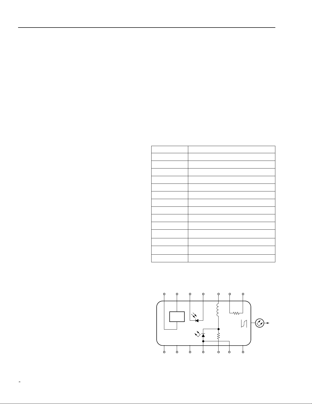
Pin Information
Pin Name
1 Thermistor
2 Thermistor
3 Laser dc Bias (cathode) (–)
4 Back-facet Monitor Anode (–)
5 Back-facet Monitor Cathode (+)
6 Thermoelectric Cooler (+)*
7 Thermoelectric Cooler (–)*
8 Case Ground
9 Case Ground
10 Case Ground
11
Laser Anode (+)
12 RF Laser Input Cathode (–)
13
Laser Anode (+)
14 Case Ground
* A positive current through the thermoelectric heat pump cools the
laser.
†Both leads should be grounded for optimum performance.
7654 321
–++ – –
L1
160 nH
TEC
†
†
TH
10 kΩ
Standard Package
The laser module is fabricated in a 14-pin, hermetic,
metal/ceramic butterfly package. The package also
incorporates a bias tee that separates the dc-bias path
from the RF input. The RF input has a nominal 25 Ω
PACKAGE
GROUNDS
8 9 10 11 12 13
Top view.
+–+
R1
20 Ω
ISOLATOR
14
1-567
impedance. The laser module is equipped with a single-mode fiber with an 8 µ m core and 125 µ m cladding.
Figure 1. Circuit Schematic
22 Lucent Technologies Inc.
°
°
1.5 µ m D2500-Type Digital
Isolated DFB Laser Module
Data Sheet
February 2000
Absolute Maximum Ratings
Stresses in excess of the absolute maximum ratings can cause permanent damage to the device. These are absolute stress ratings only. Functional operation of the device is not implied at these or any other conditions in excess
of those given in the performance characteristics of the data sheet. Exposure to absolute maximum ratings for
extended periods can adversely affect device reliability.
Parameter Symbol Min Max Unit
Laser Reverse Voltage V
dc Forward Current I
Operating Case Temperature Range T
Storage Case Temperature Range* T
Photodiode Reverse Voltage V
Photodiode Forward Current I
* Does not apply to shipping container.
RLMAX
FLMAX
C
stg
RPDMAX
FPDMAX
—2 V
— 150 mA
–40 70
–40 85
—
10 V
C
C
—1mA
Handling Precautions
Power Sequencing
To avoid the possibility of damage to the laser module
from power supply switching transients, follow this turnon sequence:
1. All ground connections
2. Most negative supply
3. Most positive supply
4. All remaining connections
Reverse the order for the proper turn-off sequence.
Electrostatic Discharge
CAUTION:This device is susceptible to damage as
a result of electrostatic discharge. Take
proper precautions during both handling
and testing. Follow guidelines such as
JEDEC Publication No. 108-A (Dec.
1988).
Lucent employs a human-body model (HBM) for ESDsusceptibility testing and protection-design evaluation.
ESD voltage thresholds are dependent on the critical
parameters used to define the model. A standard HBM
(resistance = 1.5 k Ω , capacitance = 100 pF) is widely
used and, therefore, can be used for comparison purposes. The HBM ESD threshold presented here was
obtained using these circuit parameters:
Mounting Instructions
The minimum fiber bend radius is 30 mm (1.18 in.).
To avoid degradation in performance, mount the mod-
ule on the board as follows:
1.Place the bottom flange of the module on a flat heat
sink at least 0.5 in. x 1.180 in. (12.7 mm x 30 mm) in
size. The surface finish of the heat sink should be
better than 32 µ in. (0.8 µ m), and the surface flatness
must be better than 0.001 in. (25.4 µ m). Using thermal conductive grease is optional; however, thermal
performance can be improved by up to 5% if conductive grease is applied between the bottom flange and
the heat sink.
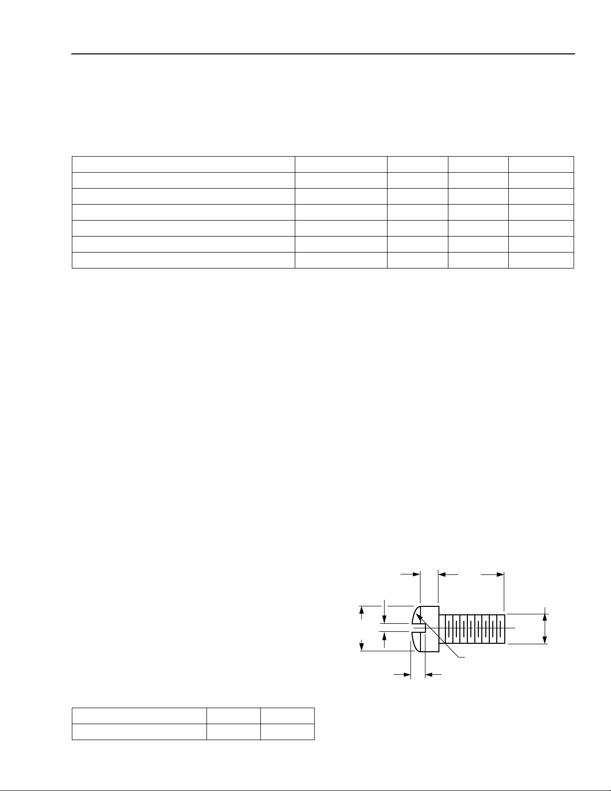
2.Mount four #2-56 screws with Fillister heads
(M2-3 mm) at the four screw-hole locations (see Outline Diagram). The Fillister head diameter must not
exceed 0.140 in. (3.55 mm). Do not apply more than
1 in.-lb. of torque to the screws.
0.062 (1.58)
0.031 (0.79)
0.140
(3.56)
Note: Dimensions are in inches and (millimeters).
0.118
(3.00)
0.129 (3.28) R
0.041 (1.04)
0.086
(2.18)
1-532
Parameter Value Unit
Figure 2. Fillister Head Screw
Human-body Model >400 V
Lucent Technologies Inc. 3
 Loading...