

AGERE D171C004CAN, D171C004BAF, D171C004BAA Datasheet
Advance Data Sheet
March 1999
D171-Type
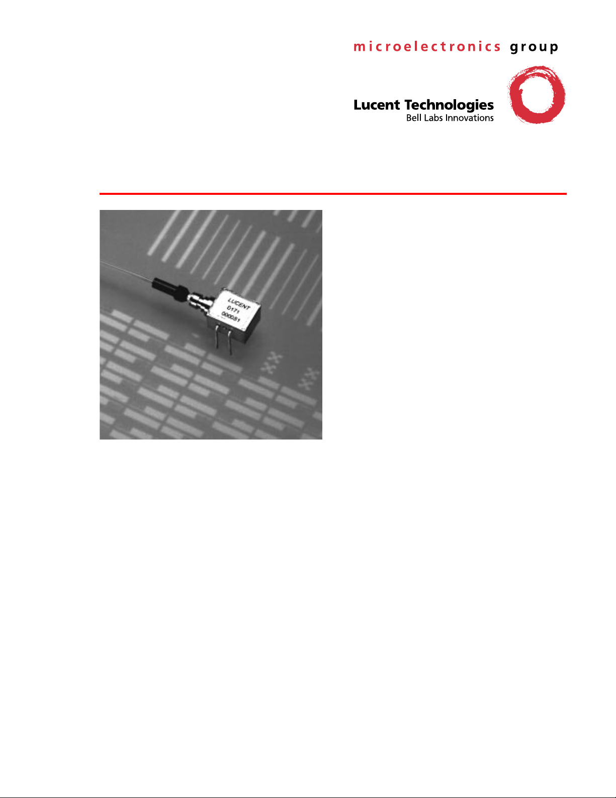
The D171-Type PIN Photodetectors feature a rear-illuminated
planar diode structure with a low-capacitance 4-mil active
area for maximum responsivity and speed.
FastLight
™
PIN Photodetectors
Features
Low-profil e, 4-lead mini-DIL pa ckage
■
— Suitable for SONET applications
High per formance
■
— High speed (<0.5 ns typical rise and fall time)
— High responsivity (0.85 A/W typical)
— Low dark current
Planar st ructure for high reliability
■
Wavelength : 1.1 µm—1.6 µm
■
50 µm core multimode fiber
■
Wide operating temperature range :
■
–40 °C to +85 °C
Wide bandwidth
■
Qualification program : Bellcor e TA-NWT-983
■
Applications
Long-reach SONET OC-3/OC-12 systems and
■
SDH STM-1/STM-4 systems
Secure digital data systems
■
Benefits
Compact si ze
■
Easily board mounted
■

D171-Type
FastLight
Advance Data Sheet
PIN Photodetectors March 1999
Description
The D171-Type Photodetector consists of a PIN coupled to a multimode fiber pigail. The device is available
in a 4-pin mini-DIL configuration (see Figure 3 and/or
Table 1) and is ideal for long-reach (SONET) and other
high-speed digital applications.
The D171-Type PIN Photodetector is a rear-illuminated
planar diode structure with a low-capacitance active
area for maximum responsivity and speed.
This device incorporates the new Laser 2000 manufacturing process from the Optoelectronics Products unit
of Lucent Technologies Microelectronics Group. Laser
2000 is a low-cost platform that targets high-volume
manufacturing and tight product distributions on all
optical subassemblies. This platform incorporates an
advanced optical design that is produced on Opto’s
highly automated production lines. The Laser 2000
platform is qualified for central office and uncontrolled
environments, and can be used for applications requiring high perfomance and low cost.
PIN 2
10 V
N
P
LOAD
LN
RN
N
P
RP
Notes:
This equivalent circuit is intended for modeling the package
capacitance. Minimum capacitance is achieved by connecting the Nside to ground, applying a negative voltage to the P-side, and allowing
the package to float (i.e., not connected to ground).
Typical values are as follows:
CO = 0.3 pF to 0.5 pF.
LN, LP = 3.0 nH.
RN, RP = 5 Ω.
CN = 0.4 pF.
CP = 0.1 pF.
CN
CO
CP
LP
PIN 2
PIN 3
LOAD
LOAD
1-697
Figure 2. Equivalent ac Circuit for Digital
Applications
12
RBIAS
PIN 3
Figure 1. Typical Bias Connection
43
1-902.a
Figure 3. D171-Type PIN Photodetector Schematic
(T op View)
Table 1. Pin Descriptions
Pin Number Description
1NC
2 Photodiode Cathode
3 Photodiode Anode
4 Case Ground
22
Lucent Technologies Inc.
 Loading...