


 Loading...
AFP
X-Ray Film Processors
"Mini-Medical" Series
Installation, Operation,
Service & Parts Manual
|
|
|
|
|
|
|
|
|
|
|
|
|
|
|
|
|
|
|
|
|
|
|
|
|
|
|
|
|
|
|
|
|
|
|
|
|
|
|
|
|
|
|
|
|
|
|
|
|
|
|
|
|
|
|
|
|
|
|
|
|
|
|
|
|
|
|
|
|
|
|
|
|
|
|
|
|
|
|
|
|
|
|
|
|
|
|
|
|
|
|
|
|
|
|
|
|
|
|
|
|
|
|
|
|
|
|
|
|
|
|
|
|
|
|
|
|
|
|
|
|
|
|
|
|
|
|
|
|
|
|
|
|
|
|
|
|
|
|
|
|
|
250 Clearbrook Rd. |
|
|
||||||||||||||||||||||||||||||
|
Elmsford, N.Y. 10523 |
|
|
|||||||||||||||||||||||||||||||
December 15, 2001 |
(914) 592-6100 |
|
|
|
|
|
|
|
|
|
|
|
|
0000061122 REV 04 |
||||||||||||||||||||

WARRANTY
AFP Imaging Corporation warrants to the original purchaser that each newAFP product is free from defects in workmanship and material for 12 months from date of installation or 18 months from date of sale, whichever occurs first. If no warranty card is returned to AFP within 30 days of installation, the maximum warranty period will be 13 months from date of shipment from AFP’s warehouse. In the event any product or component of equipment is replaced by AFP
under this warranty, such item is covered by this same warranty for the remainder of the original period or ninety days
from the date of installation, whichever is longer. AFP’s obligation during this warranty period is expressly limited to repair or, at its discretion, replacement of non-expendable original equipment or components which it finds defective.
Upon authorization from AFP, a proper party asserting a claim under this warranty shall prepay all transportation costs and return the equipment to a location specified by AFP. That party shall also bear all reasonable service and labor charges incident to any warranty claim. This warranty does NOT APPLY (1) to any expendable parts including, but not
limited to lamps, photocells, or consumable supplies (2) to any AFP product or component which has been repaired or altered with parts or by persons not approved in writing by AFP, provided, however, that such approval is not to be
unreasonably withheld, or (3) to any product on which the serial number or name has been altered, defaced, or removed. This warranty also shall NOT APPLY to any AFP product whose unsatisfactory performance or condition is due to:
-Instability of sensitized materials or chemical concentrations
and replenishing rates of chemical and wash water immersions or sequences;
-Lack of applied adequate quality production control procedures as recommended by the sensitized material and chemical suppliers;
-Changes in characteristics or process procedures made by suppliers of
sensitized materials or chemicals after delivery of the AFP product to the purchaser;
-Lack of sufficient volume of sensitized materials for economical AFP product operation;
-Failure to follow the installation, maintenance, venting, or safety procedures recommended for AFP product operation;
-Unusual physical or electrical stress;
-Accident, neglect, misuse, failure of electric power, air conditioning,
humidity control, transportation or causes other than ordinary use in the purposes for which the product was intended;
THE ABOVE EXPRESS LIMITED WARRANTY IS IN LIEU OF ALL OTHER WARRANTIES, EXPRESSED OR IMPLIED AND THERE ARE NO WARRANTIES BEYOND THOSE STATED IN THIS DOCUMENT. THE IMPLIED WARRANTIES OF MERCHANTABILITY AND FITNESS FOR A PARTICULAR PURPOSE AND ALL OTHER WARRANTIES, EXPRESSED OR IMPLIED, OR INFERABLE FROM THE COURSE OF DEALING OR USAGE OF TRADE, ARE EXCLUDED AND SHALL NOT APPLY TO THIS PRODUCT.
THE PROVISIONS FOR REPAIR OR REPLACEMENT OF DEFECTIVE PARTS PROVIDED IN THIS WARRANTY SHALL BE THE EXCLUSIVE AND SOLE REMEDY OF THE PURCHASER. AFP SHALL NOT BE LIABLE FOR ANY OTHER DAMAGES (WHETHER IN TORT, DUE TO NEGLIGENCE OR OTHERWISE) INCLUDING BUT NOT LIMITED TO, LOSS OF LABOR, TIME, MATERIALS, CUSTOMER PROFITS, GOODWILL, OR ANY OTHER INDIRECT, SPECIAL, INCIDENTAL OR CONSEQUENTIAL DAMAGES IN CONNECTION WITH THE FURNISHING, OPERATION OR FAULTY PERFORMANCE OF THIS PRODUCT. THIS EXCLUSIVE REMEDY SHALL NOT BE DEEMED TO HAVE FAILED OF ITS ESSENTIAL PURPOSE SO LONG AS AFP IS WILLING AND ABLE TO REPAIR OR REPLACE DEFECTIVE PARTS IN THE PRESCRIBED MANNER
THIS WRITING CONSTITUTES THE FINAL COMPLETE AND EXCLUSIVE EXPRESSION OF THE TERMS OF WARRANTY AND REMEDY AS AGREED TO BY THE PARTIES TO THIS SALE. AFP NEITHER AUTHORIZES NOR ADOPTS ANY STATEMENT MADE BY ANY REPRESENTATIVE WHICH DIFFERS FROM THE TERMS OF THIS WRITING AND ALL SUCH STATEMENTS ARE SUPERSEDED BY THIS DOCUMENT.
AFP IMAGING CORP. 250 Clearbrook Road, Elmsford, N.Y. 10523
0000061122

REVISION RECORD
Title: AFP X-Ray Film Processors "Mini-Medical Series"
Document Number: 0000061122
Revision |
Effective Date |
Description |
|
|
|
01 |
August 1, 1992 |
Initial Release |
02 |
January 1, 1997 |
Total Publication Revision |
03 |
April 26, 2001 |
Warranty Page Revised |
04 |
December 15, 2001 |
Total Publication Revision |
|
|
|

Index
AFP Mini-Medical
X-Ray Film Processor
Table Of Contents
Section 0 - Safety Information
Section 1 - Introduction
Content |
1-1 |
Description |
1-1 |
Operation |
1-2 |
Capabilities |
1-2 |
Transport System |
1-2...4 |
Developer System |
1-4 |
Fixer System |
1-4 |
Developer & Fixer Replenishment |
1-5 |
Anti-Crystallization |
1-5 |
Wash System |
1-5 |
"No Plumbing" System (Optional) |
1-5 |
Dryer System |
1-6 |
Cover Interlock Switches |
1-6 |
General Specifications |
1-7...8 |
Accessories |
1-9 |
Section 2 - Installation
Introduction |
2-1 |
Pre-Installation |
2-1 |
Location |
2-1 |
Dimensions & Weight |
2-2 |
Through-the-Wall Installation |
2-2 |
Ventilation |
2-2 |
Electrical |
2-2 |
Plumbing |
2-3 |
"No Plumbing" System Option |
2-3 |
Installation |
2-4 |
Set Up |
2-4 |
Assemble Stand |
2-4 |
Position Processor |
2-4 |
Connect Replenishment |
2-4 |
Replenish Mode |
2-5 |
Batch Mode |
2-6 |
Connect Plumbing |
2-7 |
"No Plumbing" Option |
2-7 |
Control Panel Position |
2-8 |
|
|
0000061122 |
I |
|
Mini Med Series

Index
Section 2 - Installation (Continued)
Processor Checkout |
2-9 |
Operational Checkout |
2-9...10 |
Transport Film |
2-11 |
Complete Checkout |
2-11 |
Processor Set Up Checklist |
2-12 |
Operational Checklist |
2-13 |
Notes |
2-14 |
Section 3 - Operation
Controls and Indicators |
3-1 |
User Controls |
3-1 |
Power Switch |
3-1 |
Manual Replenishment Switch |
3-2 |
Power ON LED |
3-2 |
Dev Temp LED |
3-2 |
Wait LED |
3-2 |
Low Dev LED |
3-2 |
Drain Valves |
3-2 |
Overflow Lines |
3-2 |
Top Cover Interlock Switch |
3-2 |
Loading Chemicals |
3-3 |
Daily Start Up |
3-4 |
Processor ON, Fill Wash Tank |
3-4 |
Check Developer and Fixer Levels |
3-4 |
Check Drive |
3-4 |
Processing Film |
3-5 |
Shutdown and Daily Cleaning |
3-5 |
Drain Wash Tank |
3-5 |
Clean Top Cover, Guides & Rollers |
3-5 |
Wipe Off Processor |
3-5 |
Quality Control |
3-6 |
Developer |
3-6 |
Fixer |
3-6 |
Replenishment |
3-7 |
Checklists for Daily Use |
3-8 |
Startup |
3-8 |
Operation |
3-8 |
Shutdown and Daily Cleaning |
3-8 |
Mini Med Series |
0000061122 |
II

Index
Section 4 - Maintenance
Maintenance Program |
4-1 |
Maintenance Records |
4-1 |
Cleaning |
4-1 |
Mini-Medical Processor Maintenance Schedule |
4-2 |
Daily |
4-2 |
Weekly |
4-2 |
Monthly |
4-2 |
Yearly |
4-2 |
Mini-Medical Processor Maintenance Log |
4-3 |
Weekly Cleaning |
4-4 |
Monthly Cleaning |
4-5 |
Clean Tanks |
4-6 |
Inspect Processor |
4-6 |
Prepare Fresh Chemicals |
4-7 |
Lubrication |
4-7 |
Annual Maintenance |
4-7 |
Removing Old Lubricants |
4-8 |
Lubrication Points |
4-8 |
Section 5 - Service
Content |
|
|
5-1 |
Troubleshooting |
|
|
5-1 |
Service Procedures |
|
|
5-2 |
Service Procedures Index |
5-2 |
||
Schematics |
|
|
5-2 |
Troubleshooting Processor Problems |
5-3...5 |
||
Service Procedure 5-1, Main Drive Belt |
5-6 |
||
Service Procedure 5-1A, |
Film Sensors/Adjustments |
5-7...8 |
|
Figure 5-1, |
Film Sensor Location Configurations |
5-8 |
|
Service Procedure 5-2, Servicing Circulation Pumps |
5-9...11 |
||
Figure 5-2, |
Recirculation Pump Head, Early Style |
5-11 |
|
Figure 5-3, |
Recirculation Pump, Later Style |
5-11 |
|
Service Procedure 5-3, Servicing Replenisher Pumps |
5-12 |
||
Service Procedure 5-4, Circuit Descriptions & |
|
||
|
Calibration Procedures |
5-13...17 |
|
Developer Temperature Control |
5-13 |
||
Developer Temperature Calibration |
5-14 |
||
Dryer Temperature Control |
5-14 |
||
Over Temperature Protection |
5-15 |
||
Dryer Temperature Calibration |
5-15 |
||
Replenishment Operation |
5-16 |
||
Replenishment Calibration |
5-16 |
||
Triacs & SCR's |
|
5-17 |
|
Outputs |
|
|
5-17 |
Fuses |
|
|
5-17 |
0000061122 |
III |
|
Mini Med Series

Index
Section 5, Service (Cont'd)
Service Procedure 5-5, Theory of Operation |
5-18...5-19 |
Solution Temperature Control |
5-18 |
Dryer Temperature Control |
5-18 |
Solution Level Sensor |
5-19 |
Automatic Shut-Off |
5-19 |
AC Interface Board |
5-19 |
Waveforms & Voltages |
5-20...5-21 |
Schematics & Wiring Diagrams |
5-22...5-30 |
Main Wiring Diagram |
5-22 |
Dryer Rack Wiring Diagram |
5-23 |
AC Interface Board Schematic |
5-24 |
Logic Board Schematic |
5-25 |
Logic Board Layout |
5-26 |
AC Interface Board Layout |
5-27 |
Ready Tone Generator Layouts & Schematics |
5-28...5-29 |
LED Board Layout & Schematic |
5-30 |
Mini Med Series |
0000061122 |
IV

Index
Section 6 - Parts
Introduction |
6-1 |
How Parts Are Listed |
6-1 |
When Ordering Parts |
6-1 |
Maintenance Kit |
6-1 |
Documentation |
6-1 |
Part Listings |
|
General Assembly |
6-2 |
Figure 6-1, General Assembly |
6-3 |
Figure 6-2a, Feed Tray & Control Chassis Assembly |
6-4 |
Figure 6-2b, Feed Tray & Control Chassis Assembly |
6-5 |
Figure 6-3, Drive System |
6-6 |
Figure 6-4, Tank/Frame Assembly |
6-7 |
Figure 6-5, Recirculation Pumps |
6-8 |
Recirculation Pump Parts (For P/N 0000021145) |
6-8 |
Wet Rack Assembly |
6-9 |
Figure 6-6, Wet Rack Assembly, Top Roller Group |
6-10 |
Figure 6-7, Wet Racks, Bottom Roller Group |
6-11 |
Figure 6-8, Wet Racks, Film Guide Group |
6-12 |
Figure 6-9, Wash Rack, Squeegee Roller Group |
6-13 |
Dryer Assembly, Front Exit |
6-14 |
Figure 6-10, Dryer Assembly, Full View |
6-15 |
Figure 6-11, Dryer Assembly, Side View |
6-15 |
Dryer Assembly, Rear Exit |
6-16 |
Figure 6-12, Dryer Assembly, Rear Exit, Full View |
6-17 |
Figure 6-13, Dryer Assembly, Rear Exit, Side View |
6-17 |
Plumbing Schematic (Early Style Parts Listing) |
6-18 |
Figure 6-14, Plumbing Schematic (Early Style) |
6-19 |
Plumbing Schematic, (Later Style Parts Listing) |
6-20 |
Figure 6-15, Plumbing Schematic (Later Style) |
6-21 |
Notes |
6-22 |
Section 7 - Accessories
Processor Support Stand |
7-1 |
Support Stand Parts |
7-2 |
Stand Turning Kit |
7-3 |
Mounting Options Utilizing Turning Kit |
7-4 |
Side Plumbing Kit |
7-5 |
Through-the-Wall Installation Kit, Front Exit |
7-6 |
Through-the-Wall Installation Kit, Rear Exit |
7-7 |
Notes |
7-8 |
0000061122 |
V |
|
Mini Med Series
Section 0
Safety Information
- General Index -
Section 0 - Safety Information
Section 1 - Introduction
Section 2 - Installation
Section 3 - Operation
Section 4 - Maintenance
Section 5 - Service
Section 6 - Parts
Section 7 - Accessories
|
AFP Mini-Medical |
0000061122 |
X-Ray Film Processors |

IMPORTANT SAFETY INFORMATION
TO REDUCE THE RISK OF INJURY OR ILLNESS, READ, UNDERSTAND, AND HEED THE INFORMATION ON THIS SHEET, ALL PRECAUTIONARY LABELS ON THE EQUIPMENT, AND ALL INSTRUCTIONS INCLUDED WITH THE EQUIPMENT BEFORE ATTEMPTING INSTALLATION, USE, OR MAINTENANCE.
WARNING: SERIOUS BODILY INJURY can result from improper handling or usage.
WARNING: NEVER move the equipment without enough help and/or lifting tools.
WARNING: ALWAYS use care when opening the shipping carton. Strapping bands can snap and injure you.
WARNING: NEVER operate the equipment without its protective panels and guards installed. Beware of rotating gears and belts, rollers, and chains, and keep from becoming entangled in them.
DANGER: POTENTIALLY FATAL VOLTAGES ARE PRESENT IN THIS EQUIPMENT.
CAUTION: NEVER make electrical connections to the equipment unless you are a qualified electrician.
WARNING: ALWAYS route power supply wiring through a nearby disconnect device.
WARNING: NEVER attempt electrical service on the equipment unless you are a qualified electronics technician.
CAUTION: ALWAYS shut off power at the disconnect device before making electrical connections or servicing electrical components.
CAUTION: ALWAYS replace fuses with those of the same type and rating.
WARNING: NEVER touch supply voltages; THEY CAN BE LETHAL.
CAUTION: NEVER operate the equipment until it is reliably electrically grounded, NOT through the water system.
CAUTION: "DEV" indicates "developer solution".
PROCESSORS AND PROCESSOR ACCESSORIES
DANGER! POISON! PROCESSING CHEMICALS MAY BE HARMFUL OR FATAL IF SWALLOWED. KEEP OUT
OF REACH OF CHILDREN. Always review and follow the hazard warnings and the ventilation, use, and disposal instructions of the chemicals manufacturer. Install all fluids correctly before operating.
CAUTION: TO AVOID POSSIBLE DRINKING WATER CONTAMINATION, make certain that all plumbing complies with local codes.
WARNING: PROCESSING CHEMICALS CAN CAUSE SEVERE BURNS. Do not get in eyes, on skin, or on clothing. Avoid breathing vapor, mist or dust, and use only with adequate ventilation. ALWAYS FOLLOW THE SAFETY RECOMMENDATIONS OF THE CHEMICALS
MANUFACTURER.
|
LITERATURE |
|
The following publications relate to safety in film processing. |
||
|
|
|
PUBLICATION |
|
AVAILABLE FROM |
|
|
|
ANSI.PH 4.37 Photographic Processing Effluents |
|
American National Standards Institute |
|
|
1430 Broadway |
|
|
New York, N.Y. 10018 |
Technical Data Sheet, Photographic Processing Wastes ( 6 pages) |
|
E.I. DuPont DeNemours and Co., Inc. |
|
|
Photo Products Dept. |
|
|
Wilmington, Delaware 19898 |
J4: Safe Handling of Photographic Chemicals |
|
Eastman Kodak Co. |
J28: Disposal of Photographic Processing Effluents and Solutions |
|
343 State Street |
J43: A Simple Waste-Treatment System |
|
Dept. 412-L |
J50: Sampling and Flow-measurement Methods |
|
Rochester, N.Y. 14650 |
J52: Disposal of Small Volumes of Photographic Processing Solutions |
|
|
K13: Photolab Design |
|
|
S39: Water Conservation in Photographic Processing |
|
|
|
|
|
The preceding information is presented as a guide to precautions associated with photographic processing. No claim is made as to the currency, accuracy or completeness of the listed information. Please do not fail to contact your chemicals supplier to obtain additional advice and assistance.
0000061122
Section 1
Introduction
- General Index -
Section 0 - Safety Information
Section 1 - Introduction
Section 2 - Installation
Section 3 - Operation
Section 4 - Maintenance
Section 5 - Service
Section 6 - Parts
Section 7 - Accessories
|
AFP Mini-Medical |
0000061122 |
X-Ray Film Processors |

Introduction
Figure 1-1, AFP Mini-Medical Series X-Ray Film Processor
Content
This manual contains instructions for installing, using and maintaining the three different models of the AFP Mini-Medical Series of X-Ray film processors. This series includes the Mini-Medical, the Mini-Medical/90 and the Mini-Medical/EP processors. With the exception of pre-set processing speed and developer temperatures, these three processors are identical in appearance, operation, maintenance and service. Differences, where existing, will be noted in the text of this manual.
Description
The Mini-Medical system includes the processor, with daylight tight film feed tray, support stand, replenishment tanks, necessary hoses and this manual.
Major processor sections and components are shown in Figure 1-1.
0000061122 |
1-1 |
Mini Med Series |
|
|

Introduction
Operation
The processor is operated from the control panel. Basic processor functions are described in the following paragraphs. Figure 1-2 is a diagram of the transport system.
Capabilities
Mini-Medical processors develop, fix, wash and dry exposed RP type medical X-ray films of all sizes, from 4" X 4" (10 X 10 cm) to 14" X 36" (35 X 91 cm).
Hourly production capacity of 14" X 17" (35 X 45 cm) sheets of film, at the indicated, preset, lead edge in to lead edge out time, is:
Model |
Lead-to-Lead |
Productivity |
Mini-Medical |
130 sec |
55 sheets per hour |
Mini-Medical/90 |
90 sec |
85 sheets per hour |
Mini-Medical/EP |
180 sec |
42 sheets per hour |
Transport System
Four removable roller rack modules transport the material being processed through the developer, fixer, wash and dryer sections.
The developer, fixer and wash sections make use of “Deep Tank” racks to maintain developing quality and improve productivity. The dryer section includes a long path length vertical dryer to assure material drying at short developing times, reduce space requirements and return the film to the operator’s position for ease of pick-up.
All racks and rollers in the wet sections and dryer are driven from a common drive shaft by a fractional horsepower ac motor.
For ease of use, and accuracy of processing, developing times and developing temperatures are factory set at the following values:
Model |
Dev. Time |
Developer Temp. |
Mini-Medical |
29 sec |
90 Degrees f (32 C.) |
Mini-Medical/90 |
22 sec |
95 Degrees f (35 C.) |
Mini-Medical/EP |
44 sec |
95 Degrees f (35 C.) |
Mini Med Series |
1-2 |
0000061122 |
|
|
Introduction
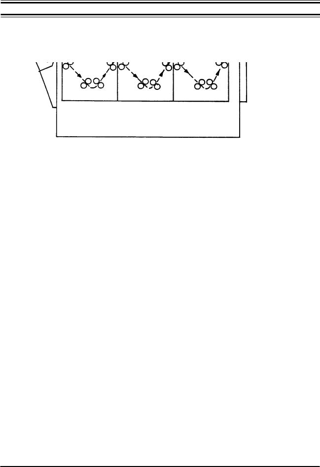
Transport System, (Cont'd)
Figure 1-2, Transport System
Before processing film, the processor must first be turned ON and allowed to bring the developer up to operating temperature.
As the processor warms up, it runs for one (1) process cycle (approximately 5 minutes) and then remains in the Stand-By mode. In this mode, only the developer heater, one dryer blower and the circulation pumps operate.
Film being fed into the processor is detected by a dual film sensor assembly located in the feed slot. When film is sensed, the Wait lamp will illuminate and stay illuminated until shortly after the trailing edge of the film has passed the sensor(s).
The above activation of the film feed sensor(s) also places the processor into Process mode, starting the transport system, the dryer heaters and blowers and, as long as the feed switch is tripped, operating the replenishment system.
Shortly after the Wait lamp extinguishes, an audible signal will sound, indicating to the operator that additional film may be fed into the processor.
An electronic holding circuit will keep the processor in Process mode for approximately 4 minutes after the feed switch is released. This will allow complete processing of the film, after which time the processor will return to the Stand-By mode to conserve energy, water and wear on the processor.
0000061122 |
1-3 |
Mini Med Series |
|
|

Introduction
Transport System,
Cont'd)
Film is pulled into the processor by the input roller set on the developer rack. The film then passes through the recirculating developer bath. As it leaves the developer, excess chemicals are squeegeed off by the exit rollers. This process is repeated in the fix, wash and dryer sections.
Processed and dried film is then deposited in the film delivery area on top of the processor.
Developer System
As the film passes through the developer tank, developer is continuously circulated and agitated around the rollers in the developer rack.
This developer circulation and agitation is provided by the developer chemistry being drawn down into the developer circulation pump, located in the base of the tank, and then being pumped back through the side of the tank, at a rate of approx. 2 gallons per minute.
The developer is replenished during operation by chemicals being drawn from the replenishment tank by a pump controlled by the replenishment circuit. This circuit operates the pump continuously, with the actual output rate, in ml/minute, being electronically controlled by the processor’s circuitry.
Developer heat is provided by a 500 watt heater located in a heat-exchanger below the tank.
Developer temperature is sensed by a temperature sensor, located in the bottom of the developer tank.
Developer temperature is factory set at the values shown on Page 1-2, and may be readjusted by the installing technician to temperature values from ambient to 115 degrees f (46 C.)
Fixer System
The film is fixed in the fix tank. Fixer is agitated, circulated and replenished in the same manner as the developer. The fixer is not heated.
Mini Med Series |
1-4 |
0000061122 |
|
|
Introduction
Developer & Fixer
Replenishment
Mini-Medical Series processors are designed to operate in either “Batch” or “Replenishment” mode. As such, replenishment chemicals may be replenished as necessary, with tank overflow being directed into a drain or collection container for disposal, or recycled until exhausted, then discarded and fresh chemicals installed. For additional information refer to the Operation and Maintenance sections of this manual.
Anti-Crystallization
To prevent the build-up of chemicals on the processing rollers, an anti-crystallization or “Jog” feature is built into all Mini-Medical processors.
This feature automatically runs the drive system at process speed for 20 seconds every 4 minutes, allowing fresh chemistry to be washed over the air-exposed rollers, effectively preventing crystallization of chemistry on the roller surfaces.
Wash System
The film being processed is washed in the wash tank before entering the dryer. The wash water solenoid is actuated during the processing cycle and refreshes the water in the wash tank with tempered water from an external source.
“No Plumbing’’
System (Optional)
The available “No Plumbing” wash water recirculation system P/N 9992305003 (115 VAC) or P/N 9992305004 (230VAC) allows the installation of Mini-Medical processors without external plumbing connections.
When using this option, wash water is recirculated from a 7 gallon reservoir, to the processor, and then back into the 7 gallon reservoir.
Processing chemistry (developer & fixer) is recirculated through each respective processing tank and replenishment container until its activity level is no longer satisfactory, at which time it is drained and replaced.
0000061122 |
1-5 |
Mini Med Series |
|
|

Introduction
Dryer System
As film passes through the dryer, it is subjected to warm air from two linear infrared quartz heating elements and a pair of fans.
Upon leaving the dryer the film is deposited in the receiving bin.
Cover Interlock Switch
To prevent accidental injury from moving parts, a mechanical safety switch is interlocked with the processor’s top cover. If the top cover is removed, the processor automatically shuts down.
Mini Med Series |
1-6 |
0000061122 |
|
|

Introduction
General Specifications
Films
RP type medical X-Ray films and compatible chemicals designed for RP type processing.
Film Size
Minimum Size: |
4" X 4" (10 X 10 cm) |
Maximum Size: |
14" X 36" (35.6 C 91.4 cm) |
Base thicknesses |
0.004 - 0.008" |
Developing Time
Factory set as follows:
Model |
Dev. Time |
Linear Speed |
Mini-Medical |
29 sec |
20" per minute |
Mini-Medical/90 |
22 sec |
36" per minute |
Min-Medical/EP |
44 sec |
10" per minute |
Developer, Fix, & Wash
Systems
Capacity: 1.9 gallons (7.2 L.).
Temperature Control:
Developer: Factory Set as follows:
Mini-Medical |
90 Degrees f. (32 C.) |
Mini-Medical/90 |
95 Degrees f. (35 C.) |
Mini-Medical/EP |
95 Degrees f. (35 C.) |
Fixer Ambient |
|
Wash: Controlled by incoming water supply, .25 GPM (.95 LPM) during process and anticrystallization cycle. There is no water flow in standby mode.
Dryer System
Temperature: Factory set at 120 degrees f. (49 C.).
0000061122 |
1-7 |
Mini Med Series |
|
|

Introduction
General Specifications,
Continued
Environmental Conditions
Temperature: |
40-80 Degrees f. |
Humidlty: |
40% - 60% RH. |
Electrical Requirements |
|
120 VAC, 15 amps, 60 Hz.
230 VAC, 7.5 amps, 50 Hz. (Optional)
Dimensions
Width 22" (56.1 Cm) |
Stand Only: |
Width 22.875" |
Height: 24.5" (62.2 Cm) |
|
Height 29.5" |
Length: 33" (84.1 Cm) |
|
Length 22.125" |
(Including feed tray) |
Allow 1" (approximately) for leveling |
|
Weight
Approximate Shipping Wt.: 110 lbs.
Approximate Operating Wt.: 160 lbs.
Air Conditioning Heat Load (Approximate)
Total Heat @ 60Hz |
Process Mode |
Standby Mode |
|
2800 B.T.U./Hour |
1800 B.T.U./Hour |
Darkroom venting is required. Use a blower and vent combination that allows for approximately 300 CFM air flow through the darkroom.
Component Power Requirements
Component |
Amperage @ 115VAC |
Solenoid |
0.10 |
Developer Heater |
4.55 |
Recirculation Pumps (2) |
0.22 Ea. |
Replenisher Pumps (2) |
0.35 Ea. |
Dryer Lamps (2) |
2.17 Ea. |
Fan Motors (2) |
0.44 Ea. |
Drive Motor |
0.76 |
Total: |
11.77 Amps |
Mini Med Series |
1-8 |
0000061122 |
|
|

Introduction
Accessories
Stand Turn Kit (Allows sideways positioning of processor on stand for access to replenisher containers) P/N 9992305001.
Side Plumbing Kit (Moves plumbing from front to side of processor) P/N 9992305002.
“No Plumbing’ Wash Water Recirculation Kit. P/N 9992305003 (115 VAC)
P/N 9992305004 (230 VAC)
Specifications are subject to change without prior notice.
0000061122 |
1-9 |
Mini Med Series |
|
|

Introduction
Mini Med Series |
0000061122 |
Section 2
Installation
- General Index -
Section 0 - Safety Information
Section 1 - Introduction
Section 2 - Installation
Section 3 - Operation
Section 4 - Maintenance
Section 5 - Service
Section 6 - Parts
Section 7 - Accessories
|
AFP Mini-Medical |
0000061122 |
X-Ray Film Processors |
Attention:
When testing or operating the processor with water (as opposed to chemistryj), there will be a
LOW LEVEL condition in effect which will disable the solution heater. This is due to the fact that water by itself cannot conduct well enough. To prevent this, add 1-2 tablespoons of salt or a cup of used or fresh developer to the developer tank.
Mini Med Series |
0000061122 |
Loading...