

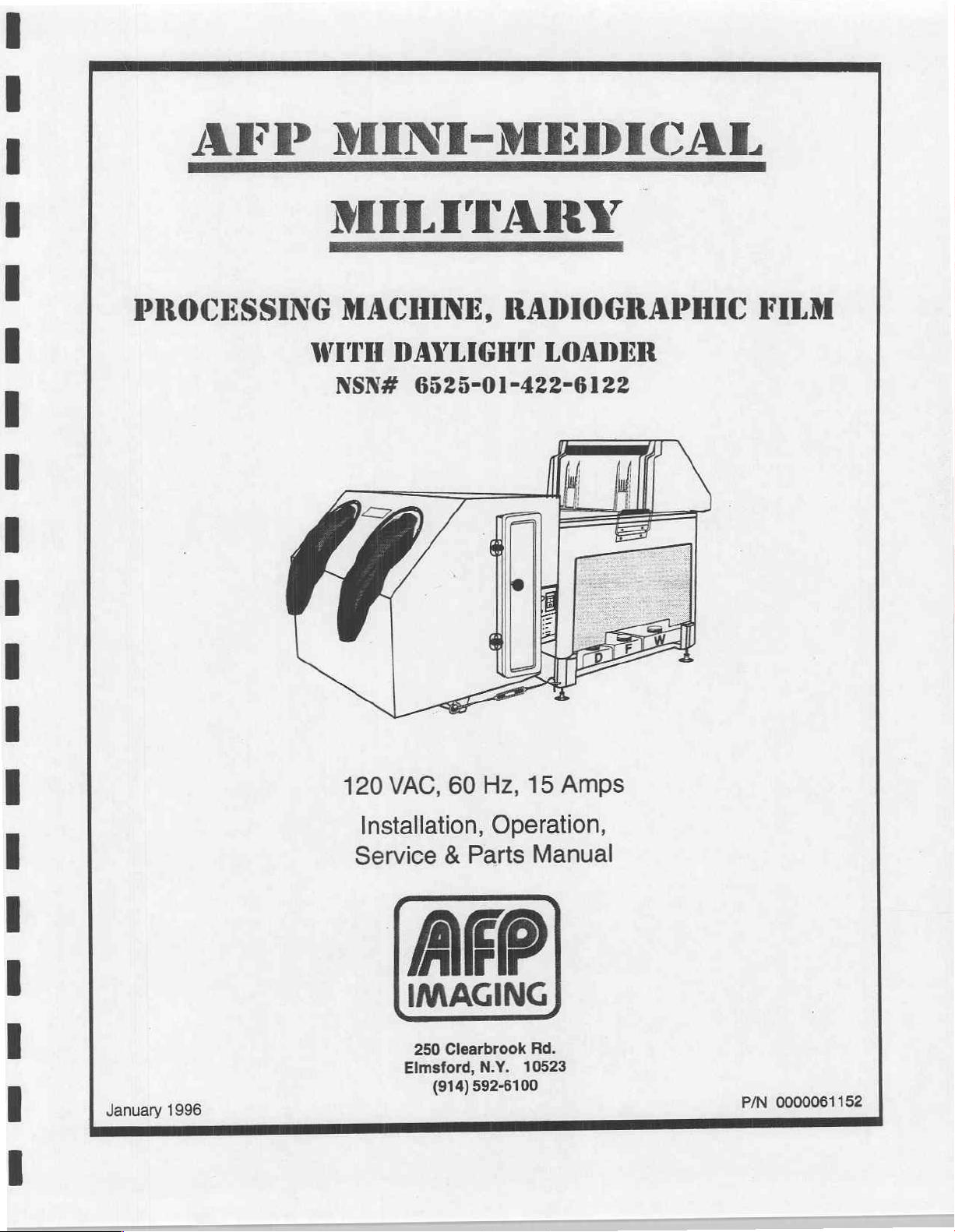
Page 1
AFP
PROCESSING
MINI-MEDICAL
MILITARY
MACHINE,
WITH
NSN#
DAYLIGHT
6525-01-422-6122
RADIOGRAPHIC
LOADER
FILM
January
1996
120
VAC,
Installation,
Service & Parts
60
Hz,
Operation,
IMAGING
250
Clearbrook
Elmsford,
(914)
N.Y.
592-6100
15
Amps
Manual
Rd.
10523
0000061152
P/N
Page 2
IMAGING
AFP
IMAGING
workmanship
within
product
the
remainder
this
warranty
components
prepay
reasonable
parts
including,
been
repaired
not
to
be
removed.
CORPORATION
and
material
30
days
of
installation,
or
component
of
the
period
which
all
transportation
service
but
or
altered
unreasonably
This
warranty
=
=
-
Instability
and
Lack
recommended
Changes
sensitized
for
of
equipment
original
is
expressly
it
finds
defective.
costs
and
labor
not
limited
with
withheld,
also
of
replenishing
of
applied
in
materials
warrants
12
months
date
of
period
or
limited
and
return
charges
to
lamps,
parts
or
or
(3)
shall
NOT
sensitized
rates
adequate
by
the
characteristics
to
of
normal
shipment
is
replaced
ninety
to
repair
Upon
authorization
the
incident
photocells,
by
persons
to
any
APPLY
materials
of
chemical
quality
sensitized
or
or
chemicals
days
equipment
to
product
WARRANTY
the
original
usage,
from
AFP
by
AFP
from
or,
in
any
warranty
or
not
approved
on
to
any
or
chemical
and
production
material
process
after
purchaser
from
the
warehouse
under
this
the
date
of
its
discretion,
from
AFP,
to
a
location
claim.
consumable
in
writing
which
the
AFP
product
concentrations
wash
water
control
and
chemical
procedures
delivery
of
that
each
new
AFP
date
of
installation.
will
be
used
to
warranty,
installation,
replacement
a
This
supplies
serial
whose
immersions
made
the
such
proper
party
specified
warranty
(2)
by
AFP,
number
unsatisfactory
procedures
suppliers;
by
suppliers
AFP
product
item
whichever
of
by
AFP.
to
provided,
or
or
product
Tf
begin
is
is
no
warranty
warranty
covered
is
longer.
free
by
non-expendable
asserting
does
any
sequences;
as
That
NOT
AFP
name
has
performance
a
claim
party
APPLY
product
however,
been
of
to
the
purchaser;
from
defects
card
is
period.
this
same
AFP’s
obligation
original
under
this
shall
also
(1)
to
or
component
that
such
altered,
or
condition
in
returned
In
the
to
event
warranty
during
equipment
warranty
bear
all
any
expendable
which
approval
defaced,
or
is
due
AFP
any
for
or
shall
has
is
to:
-
-
-
=
THE
IMPLIED
AND
WARRANTIES
WARRANTIES,
AREEXCLUDED
THE
PROVISIONS
THE
EXCLUSIVE
AGES
(WHETHER
LABOR,
TIME,
CONSEQUENTIAL
THIS
PRODUCT.
SOLONG
THIS
AND
AS
WRITING
REMEDY
STATEMENT
SUCH
STATEMENTS
Lack
of
Failure
to
recommended
Unusual
Accident,
humidity
for
which
ABOVE
EXPRESS
THERE
ARE
OF
MERCHANTABILITY
EXPRESSED
AND
SHALL
FOR
REPAIR
AND
SOLEREMEDY
IN
TORT,
MATERIALS,
DAMAGES
THIS
EXCLUSIVE
AFP
IS
WILLING
CONSTITUTES
AS
AGREED
MADE
BY
ANY
ARE
sufficient
follow
physical
neglect,
control,
for
the
product
the
or
volume
AFP
electrical
misuse,
transportation
LIMITED
NO
WARRANTIES
OR
IMPLIED,
NOT APPLY
OR
REPLACEMENT
DUE
TO
NEGLIGENCE
CUSTOMER
IN
CONNECTION
REMEDY
AND
ABLE
THE
FINAL
TO
BY
THE PARTIES
REPRESENTATIVE
SUPERSEDED
of
sensitized
maintenance,
product
operation;
stress;
failure
of
or
was
intended;
WARRANTY
BEYOND
AND
FITNESS
OR
INFERABLE
TO
THIS
OF
THE
PURCHASER.
PROFITS,
WITH
SHALL
TO
REPAIR
COMPLETE
TO
WHICH
BY
THIS
DOCUMENT.
materials
venting,
electric
causes
IS
IN
THOSE
for
or
safety
power,
other
than
LIEU
economical
procedures
air
conditioning,
ordinary
OF
ALL
OTHER
STATED
IN
FOR A PARTICULAR PURPOSE
FROM
THE
COURSE
PRODUCT.
OF
DEFECTIVE
OR
OTHERWISE)
GOODWILL,
THE
FURNISHING,
NOT
BE
OR
REPLACE
AND
THIS
SALE.
DIFFERS
PARTS
AFP
SHALL
INCLUDING
OR
ANY
DEEMED
DEFECTIVE
EXCLUSIVE
AFP
NEITHER
FROM
PROVIDED
NOT
OTHER
OPERATION
TO
HAVE
EXPRESSION
THE TERMS
AFP
use
in
WARRANTIES,
THIS
DOCUMENT.
OF
DEALING
BELIABLEFOR
BUT
INDIRECT,
FAILED
PARTS
AUTHORIZES
product
the
purposes
AND
IN
THIS
NOT
LIMITED
OR
FAULTY
OF
IN
THE
OF
THE
OF
THIS
operation;
EXPRESSED
THE
IMPLIED
ALL
OTHER
OR
USAGE
WARRANTY
ANY
OTHER
TO,
SPECIAL,
INCIDENTAL
PERFORMANCE
ITS
ESSENTIAL
PRESCRIBED
TERMS
NOR
ADOPTS ANY
WRITING
OF
TRADE,
SHALL
LOSS
PURPOSE
MANNER,
OF
WARRANTY
AND
OR
BE
DAM-
OF
OR
OF
ALL
AFP
IMAGING
CORP.
250
Clearbrook
Road,
Elmsford,
N.Y.
10523
Page 3

Warranty
Information
Section 1 -
AFP
Mini-Medical
X-Ray
Table
Introduction
Figure
with
Content
Description
Operation
Capabilities
Transport
Figure
Developer
Fixer
Developer & Fixer
Anti-Crystallization
Wash
Dryer
Cover
General
Specifications
1-1,
Daylight
1-2,
System
System
System
Interlock
Film
115VAC
Of
Contents
AFP
Mini-Medical
Loader, Storage
System
Transport
System
System
Replenishment
Switch
Military
Processor
X-Ray
and
Film
Transport
Processor
case
#1
1-1
1-2
1-2
1-2
1-2
1-2
1-3
1-4
1-4
1-5
1-5
1-5
1-5
1-5
1-6.
Section 2 -
Installation
Unpacking & Setup
Unpacking & Setup
Introduction
Pre-Installation
Figure
Location
Dimensions
Weight
Ventilation
Electrical
Plumbing
Installation
Set
Figure
Set
2-1,
Up
Unpack
Position
2-2,
Up
(Cont'd)
Instructions
Instructions
Processor & Stand
Processor
Packing
for
for
Crates
Transport
Transport
I
Case
Case
Dimensions
#1
#2
EDR
DD DE
D D
©
©
D
AMIN:
D
D
ň
©
DA
è
iù
pep
Mini
Medical
Military
Page 4
Index
Section 2 -
Set
Set
Replenish
Batch
Processor
Test
Transporting
Final
Processor
Operational
Notes
Installation
Processor
Figure
Figure
Figure
Up
(Cont'd)
Daylight
Figure
Up
(Cont'd)
Figure
Daylight
Replenishment
2-3,
2-4,
2-5,
2-6,
2-7,
(Cont'd)
Assembly
Placing
Dryer
Film
Loader
Mounting
Mounting
Loader
Mode
Figure
Mode
Figure
Checkout
Cleaning
Figure
Figure
2-8,
“Replenish”
2-9,
"Batch"
Inspection
Film
With
Before
Water
Before
Set
Up
Checklist
2-10,
Set
Test
Checklist
2-11,
Operational
Operation
Processor
Power
Storage
Assembly
Daylight
Film
Set
Up
Mode
Adding
in
Tanks
Up
Checklist
onto
Packing
Receptacle
Box
and
Cover
Loader
Storage
Mode
Box
Operation
Operation
Chemicals
as a Processor
Checklist
to
Case
#1
2-6
2-6
2-7
2-7
2-7
2-7
2-8
2-8
2-9
2-9
2-10
2-10
2-11
2-11
2-12
2-13
2-14
2-14
2-15
2-15
2-16
2-16
2-17
Section 3 -
Medical
Mini
Military
Operation
Figure
Controls
Loading
Daily
Processing
and
Indicators
User
Controls
Chemicals
Up
Start
Processor
Check
Check
Film
Daylight
3-1,
Control
Power
Manual
Power
Dev
Wait
Low
Drain
Switch
Replenishment
ON/OFF
Temp
Lamp
Dev
Valves
Overflow
Top
Cover
Fill
ON,
Developer
Drive
Loader
Operation
Panel
Lamp
(3)
Lines
Interlock
Tank
Wash
and
Fixer
II
Switch
Levels
3-
3-
3-1..
3-
3-2
3-2
3-2
3-2
3-2
3-2
3-2
3-2
3-3
3-4
3-4
3-4
3-4
3-5
3-5
Page 5
Section 3 -
Section 4 -
Operation
Shutdown
Quality Control
Checklists
(Cont'd)
and
Daily
Cleaning
Drain
Wash
Clean
Top
Cover,
Wipe
Off
Processor
Developer
Fixer
Replenishment
Manual
Replenishment
Automatic
for
Daily
Use
Startup
Tank
Guides & Rollers
Pushbutton
Operation
Shutdown
and
Daily
Cleaning
Maintenance / Storage
Maintenance
Maintenance
Cleaning
Mini-Medical
Mini-Medical
Weekly
Monthly
Annual
Special
Long
Term
Removing
Lubrication
Program
Records
Processor
Daily
Weekly
Monthly
Yearly
Figure
Or After
4-1,
Processor
Figure
Cleaning
4-2,
Cleaning
Maintenance
Maintenance
Storage & Inspection
Old
Lubricants
Points
Figure
4-3,
Maintenance
Long
Maintenance
Maintenance
Maintenance
or
Before
or
After
Notes
Lubrication
Term
Transport
90
and
(Reset
Switch)
Schedule
Storage
Schedule
Log
Log
or
Storage
Day
Plus
Storage
Information
Points
for
Periods
ひひ
WW WW
ひひ
ココ
ココ
コ
WWW WWW
WW
PEW
oooooeoeo
==
5
1
D
D
PREPRESS
D
卡
D
不
D
D
下
下
&
卡
d
下
i
下
O
aga
ser
4-7
IN
Mini
Medical Military
Page 6
Section 5 -
Service
Content
Troubleshooting
Test
Equipment
for
Service
Service
Schematics...(list
Procedures.
Troubleshooting
Service
Service
Procedure
Inspecting,
Procedure
Film
Illustration
Film
Service
Procedure
Servicing
Installation
Illustration
Service
Service
Procedure
Cleaning
Illustration
Procedure
Circuit
i
Service
Procedure
Theory
Waveforms & Voltages
Figure
Figure
Figure
Figure
Figure
Figure
Figure
Figure
and
and
Repair
Processor
Sensors
Sensors
Removal,
Descriptions & Calibration
Developer
Developer
Dryer
Dryer
Overtemperature
Replenishment
Replenishment
Triacs & Scr's
Outputs
Fuses
of
Solution
Dryer
Solution
Automatic
AC
5-1,
5-2,
5-3,
5-4,
5-5,
5-6,
5-7,
5-8,
Tool
Kit
List
Required
(list
of)
of)
Problems
5-1
Adjusting & Changing
5-1A
and
Adjustments
A.
Film
Sensor
and
Adjustments
Configuration
5-2
Circulation
B,
Pumps
Disassembly & Cleaning,
Recirculation
Pump
5-3
and
Servicing
C,
Disassembly
Replenisher
of
5-4
Temperature
Temperature
Temperature
Temperature
Control
Calibration
Protection
Operation
Calibration
5-5
Operation
Temperature
Temperature
Level
Shut-Off
Interface
Main
Wiring
Dryer
Rack
AC
Interface
AC
Interface
Logic
Board
Logic
Board
Tone
Ready
Board
LED
Control
Sensor
Board
Diagram
Wiring
Board
Board
Layout
Schematic
Generator
Schematic
the
Main
Pumps
Replenisher
Procedures
Control
Calibration
Control
Diagram
Layout
Schematic
Layout
Drive
Belt
Assembly
Pump
Schematic
&
an
nn
qo
A
a
a
ta
da
a
SU
-O0
Ga GA
вый
A
tn
GQ
Ga
q
e
GA En
ーー
En
E)
GA
ニニ
+19
Un
0moIUaauRARUVVUUNNN-
En
ニニ
と
と
En
on
Un
と
En
こと
OOo
En
„21
En
らい
Un En
らら
や
ROBA
En
©
Un
©
En
©
SRG
GA
5-28
5-29
Mini
Medical
Military
IV
Page 7
Section 6 -
Introduction
How
When
Documentation
General
Figure
Daylight
Film
Illustration
Illustration
Figure
Figure
Figure
Figure
Wet
Figure
Figure
Figure
Dryer
Figure
Figure
Figure
Plumbing
Figure
Notes
Parts
Parts
Ordering
Assembly
6-1,
Loader
Box
Assembly
6-2,
6-3,
6-4,
6-5,
Transport
6-6,
6-7,
6-8,
Assembly,
6-9,
6-10,
6-11,
Schematic
6-12,
Are
Listed
Parts
General
A,
B,
Feed Tray & Control Chassis
Drive
Tank/Frame
Wash
Wet
Wet
Wet
Dryer
Dryer
Recirculation
Plumbing
Assembly
Assembly
(parts
Daylight
Film
Loader
Box
System
Assembly
Transport,
Assembly
Transport
Transport
Transport
Front
Exit
Assembly,
Assembly,
(parts
Schematic
(parts
listing)
listing)
Assembly
Assembly
Squeegee
(Parts
Listing)
Assembly,
Assembly,
Assembly,
(parts
Full
View
Side
Pump
listing)
Top
Bottom
Film
Listing)
View
Assembly
Roller
Group
Roller
Guide
Group
Roller
Group
Group
の
ひひ
の
ひひ
の
の
ひひ
の
の
ひひ
ひひ
の
ひひ
の
の
の ひ
の
ひひ
の
の
ひひ
の
ひひ
ひみ
の
二
ー ら
らい
の
いよ
ひ
さぶ
Mini
Medical
Military
Page 8
List
of
Illustrations
Figure
Figure
Figure
Figure
Figure
Figure
Figure
Figure
Figure
Figure
Figure
Figure
Figure
Figure
Figure
Figure
Figure
Figure
Illustration
Illustration
Illustration
Waveforms & Voltages
Figure
Figure
Figure
Figure
Figure
Figure
Figure
Figure
Figure
Illustration
Illustration
Figure
Figure
Figure
Figure
Figure
Figure
Figure
Figure
Figure
Figure
Figure
1-1,
with
1-2,
2-1,
2-2,
2-3,
2-4,
2-5,
2-6,
2-7,
2-8,
2-9,
2-10,
2-11,
3-1,
4-1,
4-2,
4-3,
5-1,
5-2,
5-3,
5-4,
5-5,
5-6,
5-7,
5-8,
6-1,
6-2,
6-3,
6-4,
6-5,
6-6,
6-7,
6-8,
6-9,
6-10,
6-11,
6-12,
AFP
Mini-Medical
Daylight
Loader,
Transport
System
Processor & Stand
Packing
Placing
Dryer
Cases
Processor
Power
Positioning
Mounting
Mounting
"Replenish"
"Batch"
Setup
Operational
Control
Maintenance
Daylight
Film
Mode
Checklist
Panel
Maintenance
Lubrication
A,
Film
Sensor
B,
Recirculation
C,
Disassembly
Main
Wiring
Dryer
Rack
AC
Interface
AC
Interface
Logic
Board
Logic
Board
Ready
LED
General
A,
B,
Feed
Tone
Board
Assembly
Daylight
Film
Box
Tray & Control
Drive
System
Tank/Frame
Wash
Transport
Wet
Transports,
Wet
Transports,
Wet
Transports,
Dryer
Assembly,
Dryer
Assembly,
Recirculation
Plumbing
Military
Storage
(Daylight
Dimensions
onto
Receptacle
the
Film
Storage
Loader
Storage
Mode
Operation
Operation
Checklist
Schedule
Log
Points
Configuration
Pump
of
Replenisher
Diagram
Wiring
Board
Board
Diagram
Layout
Schematic
Layout
Schematic
Generator
Schematic
Loader
Assembly
Assembly
Chassis
Assembly
Squeegee
Top
Roller
Bottom
Film
Full
View
Side
Pump
Schematic
X-Ray
and
Transport
Packing
Box
Film
Case
Loader
Box
to
System
Case
#1
Support Bracket
Daylight
Processor
Loader
Pump
Layout & Schematic
Assembly
Roller
Group
Group
Roller
Group
Guide
Group
View
#1.
not
shown)
Page
=
いこ
D =
と
D
1
ひい
D
ささ
1
6
ぷ
1
や
も
D
と
1
ここ
こと
D
ここ
uno
e
tom
BR
Un
do
On Un
re
21
Un
(D
D
En
D
Un
D
Ca
D
1
Un En
En
En
BRIRRBOSDOR—
SS
vn
©
©
©
À
h
299999
Dia
nn
Medical
Mini
Military
VI
Page 9
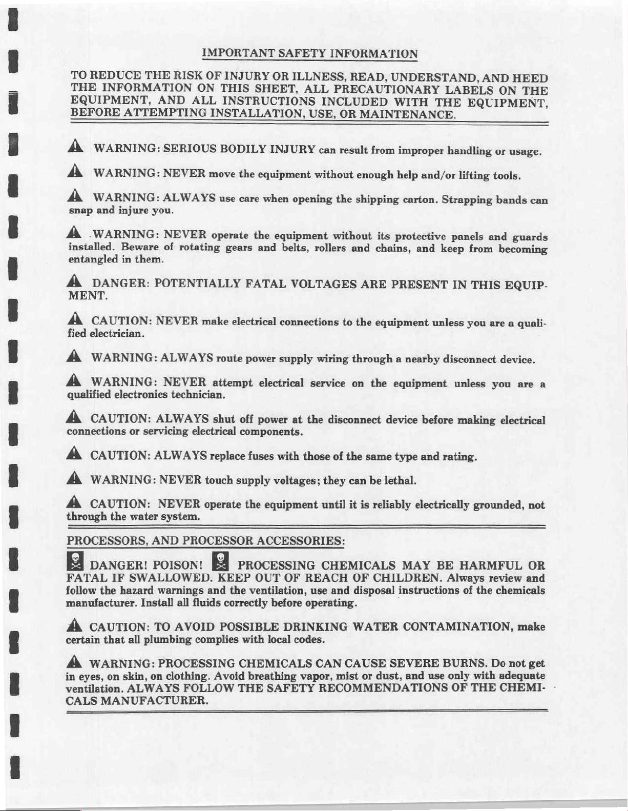
TO
REDUCE
THE
INFORMATION
EQUIPMENT,
BEFORE
Á
WARNING:
A
WARNING:
A
WARNING:
snap
and
Á
WARNING:
installed.
entangled
À
DANGER:
MENT.
A
CAUTION:
electrician.
fied
THE
AND
ATTEMPTING
SERIOUS
NEVER
ALWAYS
injure
you.
NEVER
Beware
in
of
them.
POTENTIALLY
NEVER
IMPORTANT
RISK
OF
ON
ALL
move
rotating
make
SAFETY
INJURY
THIS
OR
SHEET,
INSTRUCTIONS
INSTALLATION,
BODILY
the
use
care
operate
gears
INJURY
equipment
when
the
eguipment
and
FATAL
electrical
connections
ILLNESS,
ALL
USE,
opening
belts,
VOLTAGES
INFORMATION
READ,
PRECAUTIONARY
INCLUDED
OR
MAINTENANCE.
can
result
without
enough
the
shipping
without
rollers
and
ARE
to
the
UNDERSTAND,
WITH
from
improper
help
carton.
its
protective
chains,
PRESENT
equipment
THE
and/or
Strapping
and
keep
unless
AND
LABELS
EQUIPMENT,
handling
lifting
panels
from
IN
THIS
you
HEED
ON
or
usage.
tools.
bands
and
guards
becoming
EQUIP-
are
a
quali-
THE
can
A
WARNING:
A
WARNING:
qualified
A
connections
A
A
A
through
electronics
CAUTION:
or
CAUTION:
WARNING:
CAUTION:
the
water
PROCESSORS,
DANGER!
FATAL
follow
IF
the
hazard
SWALLOWED.
manufacturer.
A.
CAUTION:
certain
that
all
ALWAYS
NEVER
technician,
ALWAYS
servicing
ALWAYS
NEVER
NEVER
system.
AND
PROCESSOR
POISON!
warnings
Install
TO
all
AVOID
plumbing
route
power
attempt
shut
off
electrical
components.
replace
touch
supply
operate
the
PROCESSING
KEEP
and
the
fluids
correctly
POSSIBLE
complies
with
supply
electrical
power
fuses
at
with
those
voltages;
equipment
ACCESSORIES:
OUT
OF
REACH
ventilation,
before
operating.
DRINKING
local
codes.
wiring
service
the
disconnect
of
they
until
CHEMICALS
use
and
through a nearby
on the
the
can
it
is
equipment
device
same
type
be
lethal.
reliably
and
electrically
MAY
OF
CHILDREN.
disposal
WATER
instructions
CONTAMINATION,
disconnect
before
rating.
BE
Always
unless
making
grounded,
HARMFUL
of
the
device.
you
are
electrical
review
chemicals
and
make
a
not
OR
A
WARNING:
in
eyes,
on skin, on
ventilation.
CALS
ALWAYS
MANUFACTURER.
PROCESSING
clothing.
FOLLOW
Avoid
THE
CHEMICALS
breathing
SAFETY
CAN
CAUSE
vapor,
mist
or
RECOMMENDATIONS
SEVERE
dust,
and
BURNS.
use
only
OF
with
THE
Do
not get
adequate
CHEMI.
-
Page 10
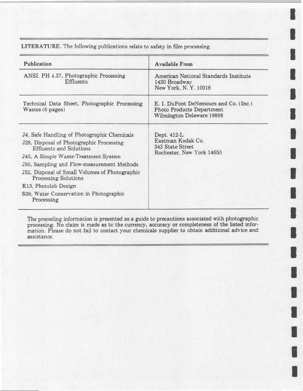
LITERATURE.
The
following
publications
relate
to
safety
in
film
processing.
Publication
ANSI.
Technical
Wastes
J4,
J28,
J43, A Simple
J50,
J52,
K13,
S39,
PH
(6
Safe
Handling
Disposal
Effluents
Sampling
Disposal
Processing
Photolab
Water
Processing
4.37,
Photographic
Effluents
Data
Sheet,
pages)
of
Photographic
of
Photographic
and
Solutions
Waste-Treatment
and
Flow-measurement
of
Small
Solutions
Design
Conservation
Volumes
Processing
Photographic
Chemicals
Processing
System
of
Photographic
in
Photographic
Processing
Methods
Available
American
1430
New
E.
I.
Photo
Wilmington
Dept.
Eastman
343
State
Rochester,
From
National
Broadway
York,
DuPont
N.
Products
412-L
Kodak
Street
New
Standards
Y.
10018
DeNemours
Department
Delaware
Co.
York
and
19898
14650
Institute
Co.
(Inc.)
The
preceding
processing. No
mation.
assistance.
Please
information
claim
do
not
is
made
fail
is
presented
as
to
to
contact
as a guide
the
currency,
your
to
accuracy
chemicals
precautions
or
completeness
supplier
to
associated
obtain
additional
with
photographic
of
the
listed
advice
infor-
and
Page 11
Section
1
Introduction
-
General
Index
-
Section
Section
Section
Section
Section
Section
1
-
Introduction
2
-
Installation
3
-
Operation
4
-
Maintenance
5
-
Service
6
-
Parts
/
Storage
AFP
Mini-Medical
X-Ray
Film
Military
Processor
Page 12
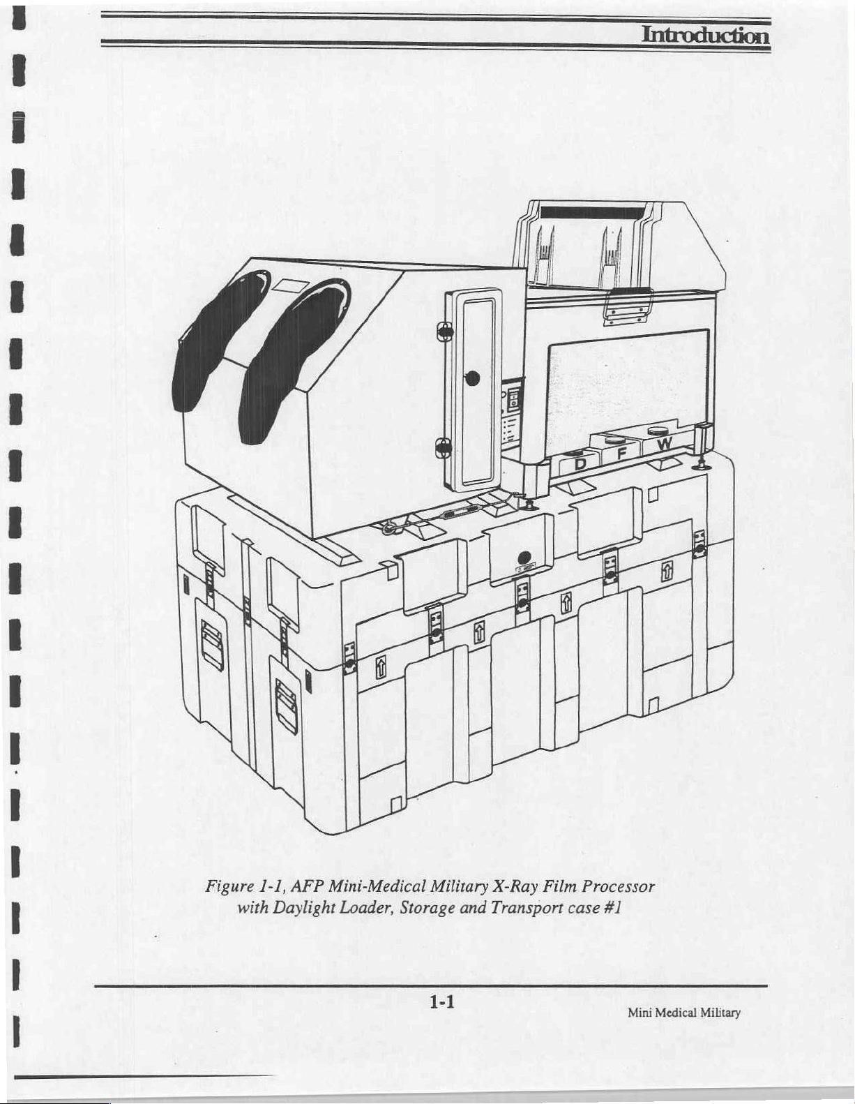
Figure
1-1,
with
AFP
Mini-Medical
Daylight
Loader,
Military
Storage
1-1
X-Ray
and
Transport
Film
case
Processor
#1
Mini
Medical
Military
Page 13
Introduction
Content
This
AFP
Description
The
loader,
necessary
The
Operation
manual
Mini-Medical
Mini-Medical
processor
contains
transport
hoses
and
is
shown
instructions
Military
system
/support
this
manual.
in
X-Ray
includes
case
(stand),
Figure
for
unpacking,
film
processor
the
processor,
replenishment
1-1.
installing,
with
with
operating
Daylight
daylight
tanks,
film
and
Loader,
tight
(Zero
storage
maintaining
Light)
bin,
film
hardware,
the
The
in
Capabilities
The
medical
Hourly
set,
time
Transport
System
Four
developer,
The
developing
vertical
and
All
shaft
processor
the
following
Mini-Medical
production
lead
for a single
removable
developer,
return
transports
is
X-ray
films
edge
in
fixer,
quality and
dryer
to
the
film
and
paragraphs.
to
roller
fixer
assure
by a fractional
operated
capacity
14" X 17”
wash
rollers
from
Military
of
all
lead
edge
transport
and
and
wash
improve
film
to
the
operator's
in
horsepower
the
control
Figure
processor
sizes,
of
out
sheet
dryer
drying
the
1-2
will
from
4" X 4"
14" X 17" (35 X 45
time
of
of
film
modules
sections.
sections
productivity.
wet
AC
make
at
short
position
sections
motor.
panel.
is a diagram
90
is
transport
Basic
develop,
(10 X 10
cm)
seconds,
120
seconds.
use
of
The
dryer
developing
for
ease
and
dryer
processor
of
the
film
fix,
wash
cm)
to
sheets
of
is
85
sheets
the
film
being
“Deep Tank”
section
times,
of
pickup.
are
driven
functions
transport
and
14" X 36"
film,
per
includes a long
reduce
system.
dry
exposed
(35 X 91
at
the
indicated,
hour.
The
processed
transports
space
from a common
are
described
RP
type
cm).
pre-
dry
to
dry
through
to
path
requirements
the
maintain
length
drive
For
ease
of
use,
and
accuracy
are
factory
Mini
Medical
Military
set
at
22
seconds
of
processing,
at
95
degrees.
1-2
developing
times
and
developing
temperatures
Page 14
Introduction
Transport
(Cont'd)
Control
With
Panel
Indicator
Lamps
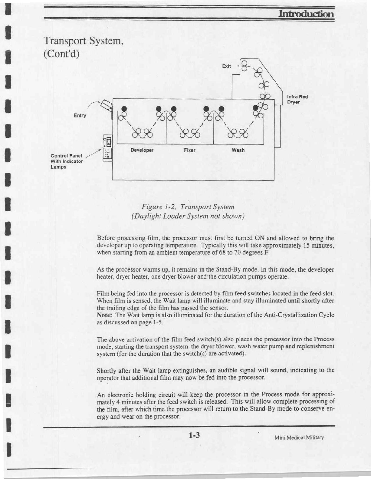
System,
LY
ラク
[E]
ES
м
LX RS
Developer
Figure
(Daylight
Loader
1-2,
Fixer
Transport
System
Exit
2%
System
not
shown)
Wash
&
do
Infra
Dryer
Red
Before
developer
when
As
heater,
Film
When
the
Note:
as
The
mode,
system
Shortly
operator
An
mately 4 minutes
the
ergy
processing
up
starting
the
processor
dryer
being
fed
film
is
trailing
discussed
above
edge
The
Wait lamp
activation
starting
(for
the
after
that
electronic
film,
after
and
wear
film,
to
operating
from
an
ambient temperature
warms
heater,
sensed,
into
of
one
the
processor
the
the
film
is
on
page
1-5.
of
the
the
transport
duration
the
Wait lamp
additional
holding
which
on
film
circuit
after
the
time
the
processor.
the
processor
temperature.
up,
it
remains
dryer
blower
Wait lamp
has
also
illuminated
film feed
system,
that
the
and
is
detected
will
passed
switch(s)
the
switch(s)
extinguishes,
may
now
will
keep
feed
switch
the
processor
must
first
Typically
of
68
in
the
Stand-By
the
circulation
by
film
illuminate
the
sensor.
for
the
duration
also
dryer
blower,
are
activated).
an
audible
be
fed
into
the
processor
is
released.
will
return
be
turned
this
will
to
70
degrees
mode.
feed
and
stay
of
places
wash
signal
the
processor.
in
This
will
to
the
ON
and
allowed
take
approximately
F.
In
this
mode,
pumps
switches
operate.
located
illuminated
the
Anti-Crystallization
the
processor
water
pump
will
sound,
the
Process
allow
complete
Stand-By
in
until
into
and
indicating
mode
mode
to
replenishment
to
bring
15
minutes,
the
developer
the
feed
slot.
shortly
after
Cycle
the
Process
to
for
approxi-
processing
conserve
the
the
of
en-
1-3
j
Mini
Medical
Military
Page 15
Introduction
Transport
(Cont'd)
Developer
System,
Film
is
pulled
being
processed
developer,
the
fix,
wash
Processed
System
As
the
film
circulated
This
developer
down
into
pumped
per
The
ishment
pump
trolled
back
minute.
developer
tank
continuously
by
into
then
excess
and
and
the
the
chemicals
and
dryer
dried
being
processed
agitated
circulation
developer
through
is
replenished
by a pump
processor’s
the
processor
passes
sections.
film
around
the
controlled
with
by
the
through
are
stripped
is
then
deposited
passes
through
the
rollers
and
agitation
circulation
bottom
during
the
circuitry.
and
by
actual
pump,
operation
output
input
roller
the
recirculating
off
by
the
in
the
the
developer
in
the
developer
is
provided
located
side
of
the
by
the
replenishment
rate
set
on
the
developer
exit
rollers.
film
delivery
by
the
developer chemistry
in
the
tank
at a rate
chemicals
circuit.
(in
ml/minute)
developer
bath.
This
process
area
on top
tank,
developer
transport.
base
of
the
of
approximately 2 gallons
being
drawn
This
being
transport.
As
of
tank
from
circuit
electronically
The
it
leaves
is
repeated
the
processor.
is
continuously
being
drawn
and
then
the
replen-
operates
film
the
in
being
the
con-
Fixer
Developer
Developer
developer
Developer
to
potentiometer
System
The
temperature
film
the
in
ished
changer
well.
as
heat
is
provided
temperature
tank.
temperature
values
located
processed
being
manner
same
passes
it
by a 500
is
sensed
is
factory
from
80
on
the
control
fixed
is
as
through
watt
heater
by a temperature
set
for
95
to
115
degrees f (46
panel.
fix
the
in
developer.
the
the
rubber
jacket
located
degrees
Fixer
tank.
fixer
The
installed
in a thermal
sensor,
and
may
C)
using
agitated,
is
heated
is
around
well
below
located
be
in
the
bottom
readjusted
the
temperature adjustment
by
outside
the
by a technician
in
of
and
the
circulated
transfer
the
tank.
of
replen-
heat
a
thermal
the
ex-
Mini
Medical
Military
1-4
Page 16
Developer & Fixer
Replenishment
The
Mini-Medical
mode.
flow
recycled
discarded
Operation
ered
Anti-Crystallization
To
“Jog”
When
20
rollers,
As
such,
being
back
and
and
in
the
prevent
feature
the
power
seconds
effectively
directed
into
fresh
Maintenance
replenishment
the
buildup
is
every 4 minutes,
processor
replenishment
is
into a drain
the
replenisher
chemicals
sections
configuration.
of
chemicals
built
into
the
Mini-Medical
is
on,
this
feature
allowing
preventing
crystallization
designed
chemicals
or
collection
holding
are
installed
of
this
on
automatically
fresh
to
operate
may
be
container
tank
installed
(batch).
manual.
the
processing
processor.
runs
chemistry
of
chemistry
in
either
“Batch”
replenished
as
for
disposal
inside
For
additional
Units
are
rollers,
the
drive
to
be
washed
on
the
Introduction
or
“Replenishment”
necessary
the
machine
information
assembled,
an
system
roller
with
(replenishment),
until
tested
anti-crystallization
at
process
over
the
surfaces.
tank
over-
or
exhausted,
refer
to
the
and
deliv-
or
speed
for
air-exposed
Wash
Dryer
Cover
System
The
water
water
System
As
film
heating
Upon
Interlock
prevent
To
with
cally
oper
cover
Note:
during
Support
C
film
being
pump
is
from
the
passes
elements
leaving
Switch
accidental
processor’s
the
down
shuts
dryer
and
will
allow
clamping
A
service
the
Kits.
processed
actuated
wash
water
through
and a pair
dryer
the
dryer
logic
all
heaters
the
machine
tool
and
is
washed
during
replenisher holding
the
dryer
of
film
the
from
injury
cover.
board
the
and
to
provided
routine
in
film
feed
it
is
blowers.
being
moving
If
controlled
blower
operate
to
maintenance
the
wash
and
refreshes
tank
subjected
processed
the
mounted
to
parts,
cover
dryer
functions
to
normally.
machine
allow
the
of
tank
before
the
water
located
warm
air
deposited
is
magnetic
a
removed,
is
such
dryer
the
operation
processor
entering
in
the
inside
the
from
two
linear
receiving
the
in
switch
safety
the
drive
the
as;
transport.
with
provided
is
the
dryer.
wash
tank
machine.
infrared
bin.
is
processor
motor,
Replacing
covers
the
A,
the
in
The
wash
with
fresh
quartz
interlocked
automati-
devel-
the
dryer
the
removed
&
B2
Bl,
1-5
Medical
Mini
Military
Page 17

Introduction
General
Materials
Material
Developing
Developer,
Specifications
RP
type
medical
Size
Minimum
Maximum
thicknesses
Base
Time
Factory
Model
Mini-Medical
set
Fix, & Wash
Capacity:
1.9
Size:
Size:
as
follows:
Military
gallons
X-Ray
(7.2
films
and
compatible
4"
X
4"
14"
X
-
0.004
Dev.
Time
22
sec.
Systems
L.).
(10
36"
(35.6
0.008"
K
10
chemicals
cm)
X
91.4
cm)
Linear
36"
designed
Speed
(91.5
cm)
for
per
RP
type
minute
processing.
Wash:
feed
Integral
Dryer
Replenisher
Two
one
processor
tanks
processor
System
Twin
thermostat.
Temperature:
Temperature
Developer
Control
Fixer
approximates
Ambient
cycle.
(1)
There
(2) 1 gallon
2.2
gallon
and
by
means
and
Infrared
Control:
is
Factory
Panel
variable
the
temperature;
no
is
System
(3.76
(8.27
are
an
of
three
as
such,
lamps
Factory
Set
as
from
developer
water
L.)
replenisher
L.)
replenisher
integral
with
part
self-priming
are
an
integral
air
circulation
set
at
130
follows:
80
to
temperature
Volume
in
flow
of
the
degrees
110
degrees
equivalent
standby
bottle
pumps.
part
mode.
bottles,
one
for the
machine.
of
the
blowers
f.
(54.5
F.
(26.8 - 37.7
to
developer
each
for
Wash
are
Solutions
These
are
machine.
and
overtemperature
C).
C)
replenishment
the
Developer
located
are
delivered
also
located
inside
in
the
safety
during
and
the
to
the
base
cutoff
Fixer
base
working
of
film
and
of
the
the
Mini
Medical
Military
Page 18
Introduction
General
(Cont'd)
Daylight
Environmental
Electrical
Dimensions
Specifications
Loader
A
rigid,
zero-light
-
dual
arm
-
cassette
-
removable,
(each
compartment
Operating
Temperature:
Humidity:
Requirements
120
VAC,
15
enclosure
holes
entry
door
2
compartment
amps,
60
with:
film
has
a
capacity
Conditions
40-90
Degrees
40% - 60%
Hz.
bin
of
RH.
with
50
films
F.
light
-
tight
14"x
cover
17"
maximum
size)
Table
top
operation:
Width
28" (71.2
Height:
Total
27"
Length:
Footprint:
Cm)
(68.6
Cm),
44.25"
28"x36"
(112.4
(7
square
with
dryer
Cm),
feet)
Weight - Processor
Approximate
Approximate
Approximate
Approximate
Shipping
Operating
Shipping
Shipping
Wt.:
Wt.:
weight
weight
Transport / Storage / Support
Case # 1 - 42.75"
Case # 2 - 30"
L. x 31"
L. x 30"
W. x 27.125"
W. x 34.375"
cover
including
110
Ibs.
160
Ibs.
in
transport
in
transport
Stand
in
Cases
H. ( for
H.
place
daylight
(without
(with
case
#1:
case
#2:
processor
(
for
daylight
loader
chemical
chemical
200
Ibs.
87
Ibs.
)
loader
solutions)
solutions)
(processor)
(daylight
loader)
)
Mini
Medical Military
Page 19
Section
2
Installation
-
General
Index
-
Section
Section
Section
Section
Section
Section
1
-
Introduction
2
-
Installation
3
-
Operation
4
-
Maintenance
5
-
Service
6
-
Parts
/
Storage
AFP
Mini-Medical
X-Ray
Film
Military
Processor
Page 20
==
Dev
ME
377353
ーー
+
les!
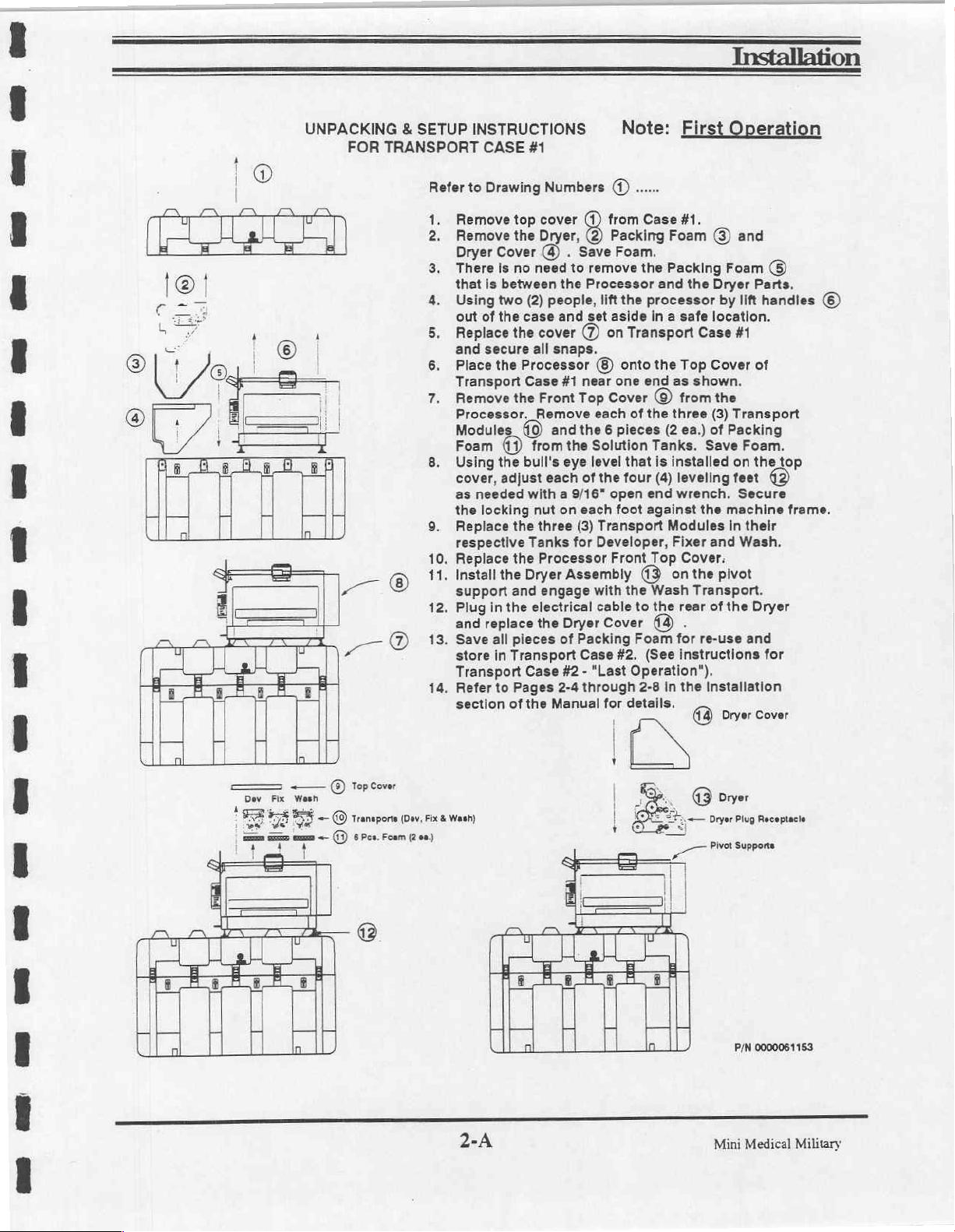
UNPACKING & SETUP
FOR
TRANSPORT
ーー
⑨
E
—O
repcew
transport
Pen
Foam
Fix
Wash
Refer
1.
È
3.
10.
11.
12.
13.
.
(Dav,
Fix & Wash)
(200)
INSTRUCTIONS
CASE
#1
to
Drawing
Remove
Remove
Dryer
There
that
Using
out
Replace
and
Place
Transport
Remove
Processor.
Modules
Foam
Using
cover, adjust
as
the
Replace
respective
Replace
Install
support
Plug
and
Save
store
Transport
Refer
section
top
the
Cover
is
no
is
between
two
of
the
the
secure
the
the
(11)
the
needed
locking
the
the
the
and
in
the
replace
all
pieces
in
Transport
to
Pages
of
need
(2)
case
all
Processor
Case
Remove
(9
from
bull's
with a 9/16"
nut
Tanks
Dryer
electrical
Case
the
Numbers
cover
Dryer,
@) . Save
the
people,
and
cover © on
snaps.
#1
Front
and
eye
each
on
three
Processor
(1)
from
(2) Packing
Foam.
to
remove
Processor
lift
set
aside
near
one
Top
Cover © from
each
the 6 pieces
the
Solution
level
of
the
open
each
foot
(3)
Transport
for
Developer,
Front
Assembly
engage
the
with
cable
Dryer
of
Packing
Case
#2 - "Last
2-4
through
Manual
Cover
for
i
+
|
Note:
......
Case
#1.
Foam
the
Packing
and
the
processor
in a safe
Transport
onto
the
Top
end
as
of
the
three
(2
ea.)
Tanks.
that
is
installed
four
(4)
leveling
end
wrench.
against
Modules
Fixer
Top
Cover.
(13
on the
the
Wash
to
the
rear
dd
Foam
for
#2.
(See
instructions
Operation").
2-8
in
the
details.
№
Eir:
@)
Foam
the
Dryer
by
location.
Case
#1
Cover
shown.
the
(3)
Transport
of
Packing
Save
on
feet
the
machine
in
and
pivot
Transport.
of
the
re-use
Installation
(3)
Dryor
43
dryer
ーー
pwr
Plug
eration
and
(8)
Parts.
lift
handles
of
Foam.
the
top
Secure
frame.
their
Wash.
Dryer
and
for
Cover
Receptacle
©)
P/N
0000061153
Mini
Medical Military
2-A
Page 21
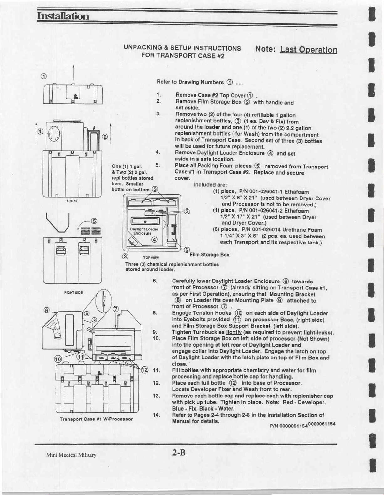
Installation
o
FRONTI
|
-
UNPACKING
One
(1)
1
&
Two
(2)
repl
bottles
here.
Smaller
bottle
on
bottom.
EI
Daylight
S
©
Three
stored
FOR
gal.
2
gal.
stored
se
ES
nr
ToP
(3)
around
&
SETUP
TRANSPORT
Refer
to
2
3.
4.
5.
©
Loader
©
view
chemical
replenishment
loader.
INSTRUCTIONS
CASE
Drawing
Remove
Remove
set
Remove
replenishment
around
replenishment
In
back
will
Remove
aside
Place
Case
cover.
]
Case
Film
aside.
two
the
of
used
be
Daylight
in
a
all
Packing
#1
in
Included
Film
Numbers
loader
Transport
for
safe
Transport
Storage
bottles
#2
@
#2
Top
Storage
(2)
of
the
bottles,
and
bottles
future
Loader
location.
Foam
are:
(1)
piece,
1/2"
and
(1)
piece,
1/2"
and
(8)
pieces,
114"X3"X6"
each
Box
Cover
(D
Box
(2)
with
four
(4)
refillable
@
(1
ea.
one
(1)
(for
Case.
replacement.
of
Wash)
Second
Enclosure
pieces
Case
X
Processor
X17"
Dryer
©)
#2.
Replace
P/N
001-026041-1
6"
X
21"
P/N
001-026041-2
X21"
Cover.)
P/N
001-026014
Transport
Note:
.
handle
Dev
&
the
two
from
set
@
removed
(used
is
not
(used
(2pcs.
and
its
Last
Operation
and
1
gallon
Fix)
from
(2)
2.2
the
of
and
gallon
compartment
three
(3)
set
from
and
secure
Ethafoam
between
to
between
ea.
respective
Dryer
be
Fatal)
Ethafoam
Urethane
used
bottles
Transport
Cover
Dryer
Foam
between
tank.)
RIGHT
Transport
Medical
Mini
SIDE
Case
#1
Military
|
|
W/Processor
6.
Carefully
front
as
(© on
front
Engage
into
and
Tighten
Place
into
engage
of
close.
Fill
processing
Place
Locate
Remove
with
of
Processor
per
First
Loader
of
Processor
Tension
Eyebolts
Film
Storage
Turnbuckles
Film
the
opening
collar
Daylight
*
bottles
each
Developer
each
pick
lower
up
Blue - Fix,
Refer
to
Pages
Manual
for
2-B
Daylight
Operation),
fits
(7)
over
Loader
(already
ensuring
Mounting
Y)
Hooks
provided
Storage
at
into
Loader
with
appropriate
and replace
full
bottle
bottle
tube.
Black - Water.
2-4
details.
Box
Support
Jightly
Box
on
left
rear
Daylight
with
the
bottle
42
Fixer
and
cap
Tighten
through
(0)
(7)
and replace
Enclosure
sitting
that
on
each
on
processor
Bracket,
(as
required
left
side
of
Daylight
Loader.
latch
plate
chemistry
cap
into
base
Wash
front
in
place.
2-8
in
the
©
towards
on
Transport
Mounting
Case
Bracket
Plate © attached
side
of
Daylight
Base,
(right
(left
side).
to
prevent
of
processor
Loader
Engage
on
top
and
water
tor
handling.
of
Processor.
to
rear.
each
with
Note;
Red - Developer,
Installation
P/N
0000061
light-leaks).
(Not
and
the
latch
of
Film
for
film
replenisher
Section
1540000061154
to
Loader
side)
Shown)
on
top
Box
#1,
and
cap
of
Page 22
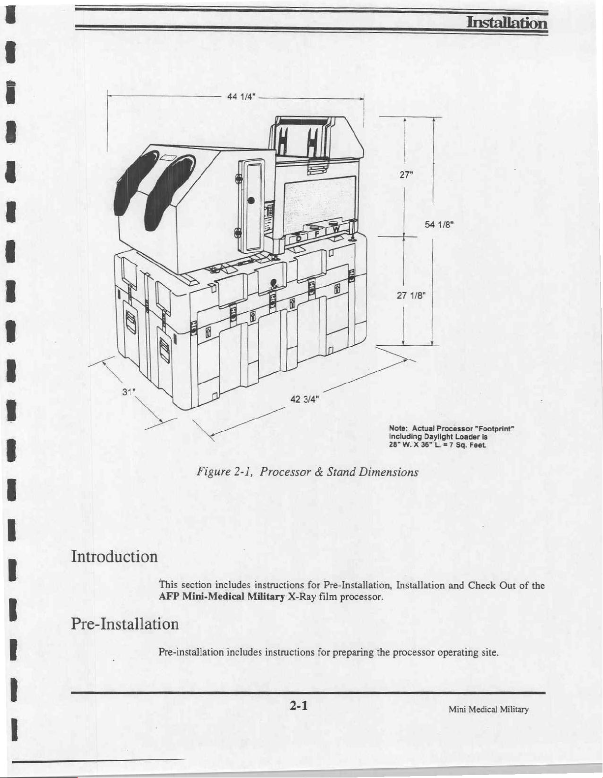
oe
Installation
44
1/4"
2
が
|
μαι
m
e
cp
Bs
Ee
1
a
—
2
Figure
3
2-1,
Processor & Stand
B
Dimensions
27
1/8"
|
Note:
Actual
Including
28"
W. X 36"
54
1/8"
|
|
Processor
Daylight
L.
= 7
"Footprint"
Loader
Sq.
Feet
is
ww EE
ww
—
Introduction
This
section
AFP
Mini-Medical
Pre-Installation
Pre-installation
includes
instructions
Military
includes
for
X-Ray
instructions
film
for
2-1
Pre-Installation,
processor.
preparing
Installation
the
processor
and
Check
operating
Mini
Medical
Out
of
site.
Military
the
Page 23

Installation
Location
Dimensions
AFP
Mini-Medical
is
made
possible
sor.
Packing
level
surface.
by
Case
Military
the
Daylight
#1
is
intended
processors
Loader
for
may
Assembly
use
as
be
operated
the
processor
ina
mounted
stand,
daylight
to
the
feed
and
should
environment.
end
of
be
placed
the
proces-
This
on
a
Mini-Medical
print)
the
unit
“front”
Packing
Weight
The
Mini-Medical
mately
To
support
Ventilation
WARNING:
tems
provide
Provide
cessor
confined
ditions.
Processors
of
work
for
of
the
Case
space.
routine
processor
#1
The processor
cleaning
is
of
sufficient
Military
160
lbs.
when
operating.
this
weight
Some
when
used
for
at
least
adequate
generates a moderate
space.
Packing
processing
in a poorly
ten
complete
ventilation
Daylight
occupy
and
below
the
size
Processor
Case
chemical
ventilated
for
proper
amount
Loader
approximately
should
preventive
feed
to
be
maintenance.
tray
must
be
used
weighs
#1
is
used
fumes
area.
If
changes
allows
of
machine
of
heat
for
air
when
flexibility
7.0
square
positioned
as
the
approx.
as a stand.
may
the
processor
per
operation
to
be
routed
support
110
irritate
hour.
operating
in
selecting
feet
allow
Drain
to
be
stand
lbs.
when
See
figure
eyes
is
to
and
operator
and
(28" x 36"
easy
access
tubes,
leading
readily
for
processor
empty,
2-3.
and/or
operate
in a confined
comfort.
must
not
processor
actual
foot-
to
all
sides
out
of
accessible.
operation.
and
approxi-
respiratory
area,
The
be
placed
site
and
con-
of
the
The
sys-
pro-
in
a
Electrical
Medical
Mini
Military
Electrical
sor
dot)
connections
plugs
into a standard
grounded
plug
must
120
assembly
include a ground
VAC,
60
Hz,
15
is
provided.
2-2
and
conform
amp., 3 wire
to
military
outlet. A hospital
codes.
The
grade
proces-
(green
Page 24
Pre-Installation,
(Cont'd)
Plumbing
WARNING:
mended
The
Military
1. A water
2. A sink
safety
following
Processor:
or
cleaning
3. A drain
Caution:
photographic
or
In
Obey
all
precautions
plumbing
source
film
for
tub,
with
transport
collection
some
situations,
processing
instructions
when
handling,
requirements
wash
water
and
running
tempered
modules.
system
suitable
regulations
wastes
other
of
the
chemical
using
are
recommended
for
cleaning
water,
for
may
than
in
manufacturer,
and
disposing
for
the
approximately
disposing
require
the
of
the
sanitary
and
of
chemicals.
installation
processor.
12" X 16",
photographic
capturing
sewer
system.
follow
of
the
Mini-Medical
for
chemical
and
safe
all
recom-
use
when
wastes.
disposal
of
2-3
©
Mini
Medical
Military
Page 25
Installation
Installation
Set
Up
NOTE:
container
Contents:
1.
2.
3.
4.
Contents:
1.
2.
3.
Do
for
Main
Processor
Wash
attached
is
Top
Front
Infrared
Manuals
Daylight
Film
Storage
Replenishment
&
transport
Note:
not
unpack
evidence
Packing
installed
Packing
Three
in
with
in
the
to
Cover
transport
Dryer
(2)
Loader
Box
Chemistry
of
solutions.
(3)
the
Processor
replenishment
the
processor
damage.
of
Case
#1
Assembly
the
Processor
Processor
(1)
(1);
Case
#2
Assembly
with
hinged
Containers
containers
Base
until
(Will
serve
(includes
Base
Dryer
(1)
are
solution
three
solution
Pan.
cover
cover
and
to
be
for
use
and
filled
during
you
have
as
the
processor
[3]
film
sections).
-
(1)
security
(6),
with
with
processing
held
ready
thoroughly
stand
transports
The
Film
straps
solid
for
later
reusable
(1)
screw
and
(Includes
(8)
replenishment
inspected
during
for
Developer,
Storage
foam
caps
for
solutions
three
(3)
use.
the
shipping
operation)
Fixer
Support
are
Bracket
packing
safe
storage
and
installed
to
be
filled
and
pad.)
Unpack
Position
1.
Open
2.
Carefully
Carefully
and
Processor.
cate
proximity
Processor
Position
supply.
3.
Using
Using
ing
feet
directions.
4.
Identify
Transports.
spect
from
use
when
after
Packing
set
aside
Packing
Packing
Use a trenching
two
the
each
under
its
Case
lift
and
lift
and
in a safe
Close
Case
to
120VAC
Case
people,
bull's
eye
with
the
Tighten
and
remove
Inspect
of
the
each
packing
contents
#1
remove
remove
Packing
#1
#1
tool
carefully
level
9/16"
the
from
all
racks
transport
for
are
removed.
and
identify
the
the
location.
Case
in
the
desired
60HZ
on a flat,
if
necessary
position
that
open-end
locking
the
components
for
loose
in
the
Processor
Rear
Cover
Remove
#1
(This
position
power
source
level
surface
to
the
is
installed
wrench
nuts
against
Processor
at
parts
its
respective
redeployment.
contents
Assembly
and
the
two
case
for
and
within 4 feet
prepare
processor
on
the
provided
the
Assembly
this
time
or
screws.
tank.
Store
all
referenced
using
Dryer
Transport.
(2)
Manuals
serves
as
the
processing
solution
the
surface.
on
Packing
top
cover,
until
machine
the
Developer,
for
any
Remoye
Retain
packing
material
above.
the
two
provided
Stand
X-Ray
waste
collection
of a 120
Case
adjust
the
processor
frame.
visible
the
foam
the
packing
handles provided.
Unwrap
for
the
shipping
in
the
next
operation).
films.
VAC
Fixer and
Packing
Consider
point.
60
#1 ( See
four
(4)
is
level
damage.
packing
material
HZ
Fig.
Case
transport
to
the
power
level-
in
Wash
material
for
Lo-
2-3
).
both
In-
later
#2
Medical
Mini
Military
2-4
Page 26
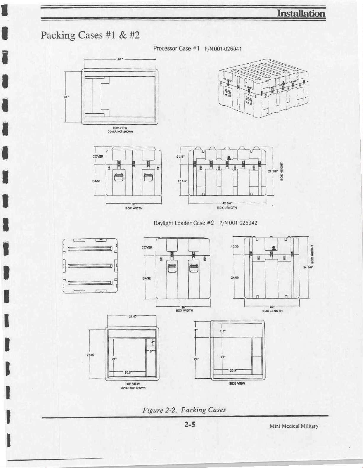
Packing
Cases
#1 & #2
Fa
Processor
Case
#1
P/N001-026041
Figure
2-2,
Packing
2-5
Cases
Mini
Medical
Military
Page 27
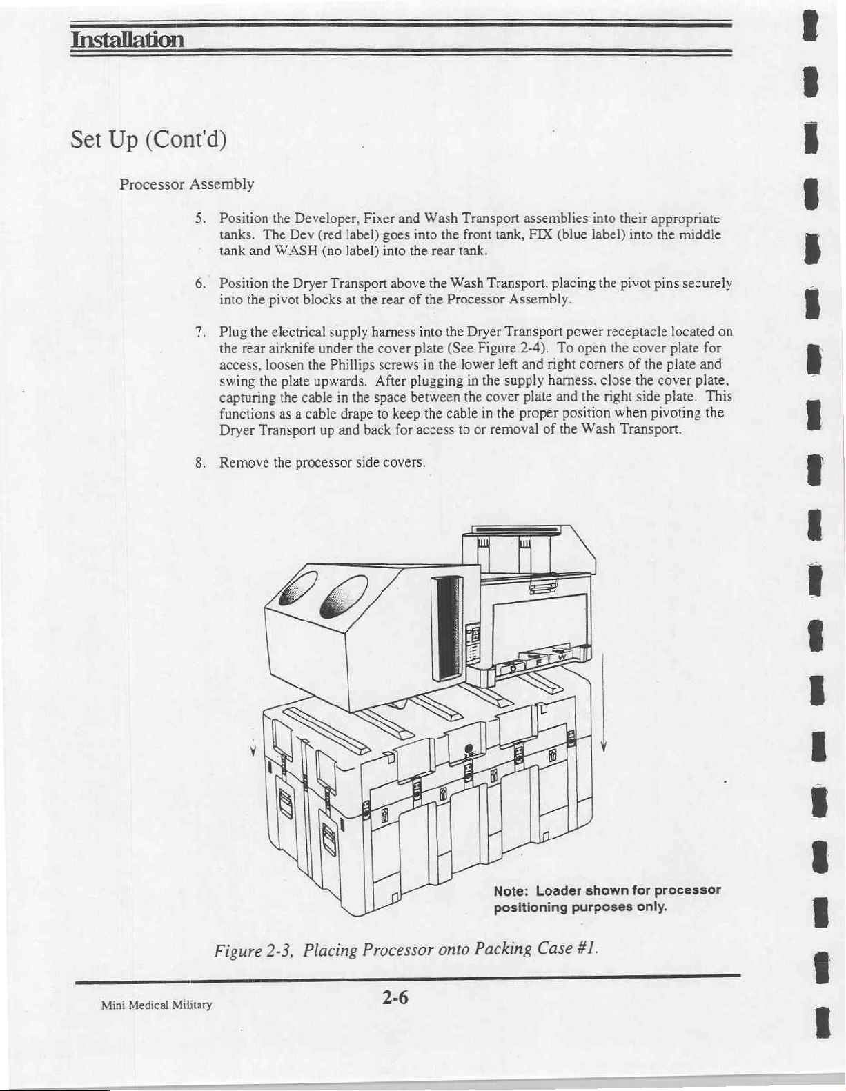
Set
Up
(Cont'd)
ww
Processor
Assembly
5.
Position
tanks.
tank
6.
Position
into
the
7.
Plug
the
rear
access,
swing
capturing
functions
Dryer
8.
Remove
the
Developer,
The
Dev
and
WASH
the
Dryer
pivot
the
electrical
airknife
loosen
the
plate
the
as a cable
Transport
the
processor
(red
(no
Transport
blocks
supply
under
the
Phillips
upwards.
cable
in
up
and
Fixer
label)
label)
at
the
harness
the
After
the
space
drape
back
side
and
goes
into
into
the
above
rear
of
cover
plate
screws
plugging
between
to
keep
for
covers.
Wash
the
rear
the
Wash
the
Processor
into
the
(See
in
the
the
cable
access
Transport
front
tank,
tank.
Transport,
Assembly.
Dryer
Transport
Figure
lower
left
in
the
supply
the
cover
in
the
to
or
removal
assemblies
FIX
(blue
placing
power
2-4).
To
open
and
right
corners
harness,
plate
and
the
proper
position
of
the
Wash
into
their
label)
into
the
pivot
receptacle
the
cover
of
close
the
right side
when
Transport.
appropriate
the
middle
pins
securely
located
plate
for
the
plate
and
cover
plate,
plate.
This
pivoting
the
on
su
Medical
Mini
Figure
Military
2-3,
Placing
Processor
2-6
onto
Note:
positioning
Packing
Loader
purposes
Case
shown
#1.
for
processor
only.
nan
w
ceo
um
UB
=
Page 28

Installation
Set
TOP
FOR
WITH
FILM
Up
(Cont'd)
LOCK
PLATE
ENGAGEMENT
TOP
LATCH
BOX
DOOR
Figure
Figure
2-4,
2-5,
Dryer
Film
Power
LOWER
ENGAGEMENT
Storage
Receptacle
STEEL
POSITIONING
Box
and
LATCH
WITH
Cover.
PLATE
ANGLE
DAYLIGHT
FOR
LOADER
a
o
_
|
9.
Open
Packing
in a safe
repacking
Daylight
Loader
10.
The
the
the
11.
Mount
Note:
Assembly
Daylight
processor
front
the
Arm
Case
location.
for
Store
redeployment.
Loader
by
four
of
the
processor
Daylight
holes
face
#2.
Remove
all
processor
Assembly
(4)
1/4-20
by
Loader
Assembly
forward
contents
Mounting
screws.
three
(3)
in
front
2-7
(referenced
packing
Plate
The
Film
8-32
screws.
to
the
Mounting
of
the
Processor
on
materials
is
in
supplied
Feed
Tray
Plate
Assembly.
page
4)
this
case
secured
is
supplied
(See
Mini
and
put
for
later
to
the
Figure
Medical
aside
use
when
front
of
secured
2-6).
Military
to
Page 29
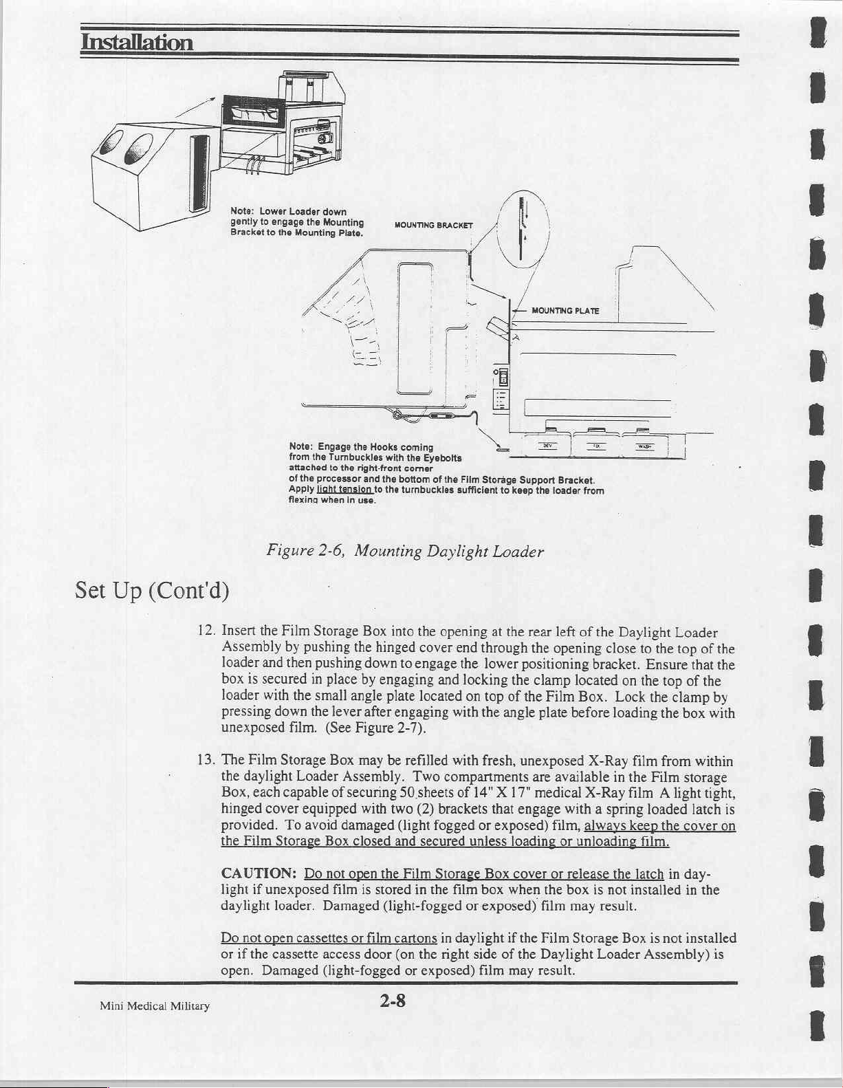
Note:
Lower
Loader
down
the
Mounting
Mounting
Note:
Engage
from
the
Turnbuckles
attached
to
of
the
processor
Apply
light
flexina
tension
when
2-6,
Plate.
the
Hooks
the
right-front
and
the
to
in
use.
Mounting
MOUNTING
BRACKET
A
coming
with
the
Eyebolts
corner
bottom
of
the
turnbuckles
the
Daylight
sufficient
Set
Up
(Cont'd)
gently
to
engage
to
Bracket
Figure
the
[
Film
X
À
i
<
Storage
Support
to
keep
Loader
Bracket.
the
loader
P%
from
12.
Insert
the
Film
Storage
pushing
Assembly
loader
box
loader
pressing
unexposed
13.
The
the
Box,
hinged
provided.
the
CAUTION:
light
daylight
Do
not
or
if
Mini
Medical
Military
open.
by
then
and
secured
is
the
with
down
film.
Film
Storage
daylight
each
capable
cover
To
Film
Storage
if
unexposed
loader.
open
the
cassette
Damaged
pushing
in
small
the
Loader
equipped
avoid
Do
cassettes
Box
into
hinged
the
to
down
engaging
by
place
plate
angle
engaging
after
lever
Figure
(See
Box
Assembly.
of
securing
damaged
Box
closed
not
open
film
Damaged
or
access
(light-fogged
2-7).
may
be
refilled
50
with
two
(light
and
the
Film
is
stored
(light-fogged
film
cartons
door
(on
or
2-8
the
opening
end
cover
engage
and
located
with
with
Two
compartments
sheets
of
(2)
brackets
fogged
secured
Stora:
in
the
film
in
daylight
the
right
exposed)
at
the
through
lower
the
locking
of
top
on
angle
the
fresh,
14" X 17"
that
or
exposed)
unless
ox
box
or
exposed)
if
side
of
film
rear
left
opening
the
positioning
clamp
the
Film
the
plate
unexposed
are
available
medical
engage
loading
cover
when
the
the
may
with a spring
film,
or
or
rel
the
box
film
Film
Daylight
result.
of
the
Daylight
close
bracket.
Lock
loading
X-Ray
in
X-Ray
always
is
not
result.
Loader
on
Box
located
Box.
before
unloading
may
Storage
Loader
top
the
to
Ensure
the
the
film
the
Film
film A light
loaded
keep
film.
e
latch
installed
is
Assembly)
that
of
top
clamp
box
the
from
storage
latch
the
cover
in
day-
in
not
installed
the
of
the
the
by
with
within
tight,
is
on
the
is
=
es
un
=e
Page 30
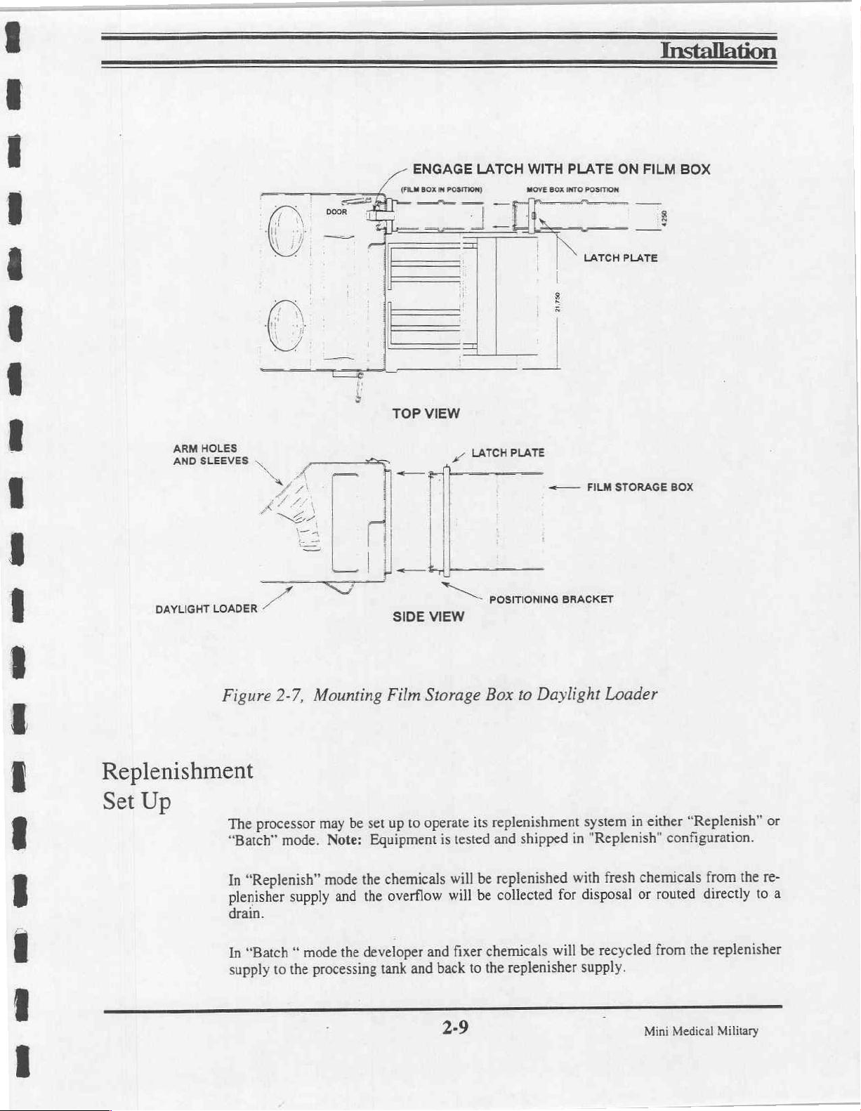
ARM
HOLES
AND
SLEEVES
DAYLIGHT
LOADER
О
O
一
一
、
Ll,
s
—
~
==,
一
一
è
=
|
“ld
Va
(FILM
6
1
호
는
一
-一
TOP
p
i
il
Я
SIDE
ENGAGE
BOX
mM
POSITION)
——
VIEW
e
|
|
|
|
|
==
VIEW
LATCH
—
—
πα
A
Ph
一 = me-
LATCH
PLATE
POSITIONING
WITH
MOVE
BOX
x
a
PLATE
INTO
POSITION
N
LATCH
Mg
=—
BRACKET
i
FILM
ON
FILM
в
PLATE
STORAGE
BOX
후
BOX
Figure
Replenishment
Set
Up
The
“Batch”
“Replenish”
In
plenisher
drain.
“Batch
In
supply
2-7,
Mounting
processor
mode.
supply
mode
“
to
the
processing
may
Note:
mode
and
the
Film
up
set
be
Equipment
chemicals
the
overflow
the
developer
tank
Storage
operate
to
is
and
and
back
2-9
Box
its
tested
be
will
be
will
fixer
to
the
to
Daylight
replenishment
shipped
and
replenished
collected
chemicals
replenisher
for
will
Loader
system
in
with
disposal
be
supply.
in
"Replenish"
fresh
or
recycled
"Replenish”
either
configuration.
chemicals
routed
from
Mini
from
directly
replenisher
the
Medical
Military
the
to
or
re-
a
Page 31

Installation
Replenish
Mode
In
“Replenish”
processing
overflow
manner,
operation.
as
follows.
1.
Place
the
Note
Attach
replenisher
tainer.
Route
overflow
Attach
isher
Route
overflow
mode,
tank.
Excessive
port
and
into
constant
To
the
corresponding
identification
the
pump
the
processing
install
three
the
screw
pump
red
developer
container
the
screw
(middle
blue
container
the
(3)
cap
cap
fixer
fresh
replenisher
chemicals
either a container
chemical
processor
Replenishment
tanks
in
the
labels;
(front
or
or
Developer,
on
the
position)
drain
drain
on
the
position)
drain
hose
drain
for
Chemistry
Base
red
developer
hose
line.
blue
fixer
to
the
and
line.
in
"Replenish"
to
will
be
pumped
the
processing
for
disposal
strength
Pan
of
the
Fixer,
replenisher
the
fitting
and
red
overflow
replenisher
fitting
on
blue
overflow
from
tank
or
an
may
be
maintained
mode
replenishment
Containers
Processor
Wash.
pickup
on
the
developer
hose
pickup
the
fixer
hose
the
replenisher
will
flow
out
appropriate
in
their
Assembly
from
hose
replenishment
from
drain
for
longer
operation,
proper
(See
hose
from
replenishment
the
processor
from
the
the
processor
supply
of
the
positions
Figure
the
fixer
container.
to
tank
line.
In
periods
proceed
under
2-8).
developer
con-
to
replen-
to
an
at
this
an
the
an
of
Attach
water
replenisher
container.
Place
the
processor
CAUTION:
that
such
connections
drain
NOT
DO
reactions
will
the
screw
clear
to
the
you
If
the
quickly
cap
on
the
pump
(rear
wash
water
overflow
are
are
processor
damage
OVERFLOW
Waste
container
draining
in
accordance
into
TO
ORAM)
clear
position)
drain
hose
your
any
the
pipes.
NOTE:
‘TRE
wash
water
to
the
and
clear
or
drain.
processor
with
codes.
lines
drain
(Fa
replenisher
fitting
wash
directly
are
that
on
the
water
into
made
pickup
wash
overflow
sanitary
a
copper
of
hose
water
LI
DRAIN
VALVES
ENDS
OF
DRAM
LOCATED
HOSES
roruus
AT
(HOT
SHOWN)
from
the
wash
replenishment
hose
from
the
certain
pipe
be
chemical
as
sewer,
Mini
Medical
Military
Figure
2-8,
"Replenish"
2-10
Mode
Operation
Page 32

Installation
=
ag
Se
de
πω
Se
M
Batch
Mode
In
“Batch”
cessing
recycled
tank
disposed
To
install
(See
Figure
1,
Route
to
the
2.
Route
same
3.
Route
fixer
4.
Route
container
mode
the
replenisher
and
will
then,
again.
As
the
chemical’s
of
and
new
chemistry
the
processor
2-9)
the
red
developer
developer
the
container
the
replenishment
the
replenishment
red
developer
as
the
blue
fixer
blue
fixer
as
the
fixer
will
via the
tank
processing
installed.
for
“Batch”
replenisher
container
drain
hose
developer
replenisher
container
drain
filled
line
and
replenisher
be
recycled
overflow
strength
mode
replenishment
pickup
hose
filled
and
red
overflow
replenisher
pickup
hose
with
blue
overflow
pickup
fixer
hose
from
the
port,
return
becomes
from
the
with
developer
hose
pickup
from
tube,
the
fixer
replenisher.
hose
from
replenisher
to
the
replenisher
depleted,
operation
developer
proceed
chemistry.
from
the
replenisher
the
processor
supply
processor
to
the
supply
the
entire
batch
as
follows:
replenisher
to
pump
to
to
the
pro-
to
be
pump
the
the
same
is
2
am
ewe
μαι
©
©
5.
6.
NOTE:
DRAIN
HERE
AND
(NOT
SHOWN)
TO
ALLOW
Route
the
pump
to
the
Route
the
processor
Note:
overflow
HOSES
ARE
ARE
USE
In
hose.
(NOT
24"
IN
REMOTED
WITH
THE
clear
wash
wash
clear
wash
to
the
same
all
of
the
SHOWN)
LENGTH.
THE
TO
DAYLIGHT
water
water
water
container
above
EXIT
DRAIN
THE
END
LOADER.
replenisher
replenisher
drain
wash
cases, a 7/8"
THE
MACHINE
VALVES.
OF
THE
HOSES
pickup
container
hose
and
the
water
replenisher
diameter
σ
М
7
NOTE:
INSTEAD
TO
GO
TO
THEY
SEPARATE
ARE
REPLENISHMENT
ROUTED
hose
from
containing
clear
wash
pickup
hole
must
Fm
OF
OVERFLOW
CONTAINERS
INTERNALLY
CHEMISTRY
CONTAINERS.
the
wash
clean
water
be
added
=
HOSES
OR
BACK
TO
water
wash
water.
overflow
hose.
to
accept
pos
ae
EXITING
HERE
DRAIN(S),
THE
replenisher
from
the
the
παω
ama
Figure
2-9,
"Batch"
2-11
Mode
Operation
Mini
Medical
Military
Page 33
Installation
Processor
Inspection
Following
CAUTION:
READING
WARNING:
the
wall
plug.
Inspect
1.
2.
3.
4.
and
Open
tanks.
valves.
Inspect
hose
at
Check
Check
Before
set
up,
DO
THE
During
clean
the
drain
Use
warm
all
hoses
one
end,
and
tighten
that
processor
inspect
NOT
POUR
NEXT
this
the
processor
valves
water
to
check
flush
if
Adding
the
processor
CHEMISTRY
PAGE.
inspection,
tanks,
on
the
front
to
rinse
for
foreign
with
water
necessary,
is
level
from
Chemicals
as
described
INTO
be
sure
that
film
transports
of
the
processor
each
tank
clear
matter.
and
reconnect.
loose
hose
clamps
front-to-rear
below
THE
PROCESSOR
the
processor
and
hoses
for
of
dust
To
remove
and/or
and
side-to-side.
to
make
power
as
the
developer,
and
debris.
debris
hardware
sure
it
is
ready
TANKS
is
disconnected
described
fixer
Close
if
found,
on
the
Correct
for
use.
UNTIL
below:
and
wash
all
drain
disconnect
processor.
as
necessary.
at
Medical
Mini
Military
2-12
Page 34

Installation
Test
Checkout
Read
Developer
WARNING:
1.
2.
3.
4.
5.
6.
7.
With
these
Close
If
not
Carefully
the
from
Water
instructions
or
Fixer
Never
the
tank
already
pour
plastic
the
bottom.
PURPOSES
Replace
Remove
With
Caution:
Switch
the
the
top
top
Power
Never
solutions
drain
done,
about
fill
mark
ONLY.
front
front
Switch
Power
in
Tanks
completely
in
operate
the
valves.
remove
1.5
gallons
located
Do
Not attempt
FILM
cover
and
cover
and
OFF,
attempt
Switch
to
to
before
the
tanks
processor
the
three
of
warm
on
the
inside
to
fill
WILL
NOT
check
bull's
install
all
plug
in
operate
ON.
the
starting
or
replenisher
without
film
the
three
the
the
an
transports
water
into
of
the
tank
tank
BE
PROCESSED
eye
level.
film
power
processor
processor.
containers.
electrical
and
set
each
of
wall
on
to
the
overflow.
Re-level
transports
cord.
without
For
ground
aside.
the
solution
the
non-drive
OR
FIXED.
the
unit
in
their
liquid
in
testing,
connection.
do
tanks.
side,
THIS
IS
FOR
if
necessary.
appropriate
the
tanks.
not
use
Fill
4"
up
TEST
tanks.
to
8.
The
the
recirculation
9.
Inspect
10.
Carefully
necessary.
11,
Operate
developer,
12.
Activate
and
the
sensor.
13.
Set
14.
When
metallic
temperature
temperature
transport
all
rack
inspect
the
Manual
fixer
either
every
few
In a few
the
Temperature
the
Dev
thermometer.
does
as
system
will
pumps
modules
the
underside
Replenishment
and
wash
Film
Feed
seconds
seconds
Potentiometer
Temp
not
outlined
run
at
will
operate
to
verify
tanks
switch
the
replenishment
the
lamp
turns
not
is
it
If
agree
with
in
Section
Process
of
are
and
that
they
the
processor
switch
full
of
speed
the
water
with a piece
pumps
Wait
light
located
OFF,
check
correct
the
for
potentiometer
5,
Service.
for
the
dryer
heaters
are
turning
for
to
run
the
to
the
of
material,
will
will
go out
on
the
control
the
temperature
film
the
duration
any
replenishment
overflow
cycle.
of
and
freely.
signs
of
The
Remove
and
the
panel
fans
Wait
of
be
will
you
dial
setting,
one
processing
will
leakage.
pumps
port.
light
beeper
to
95
the
developer
using
adjust
be
activated.
Correct
until
will
the
film
will
sound.
degrees
the
if
or
the
cycle,
the
turn
from
F.
with
actual
if
ON
a
2-13
Mini
Medical
Military
5
Page 35
Installation
Transporting
Transport
necessary,
1.
19
3.
Final
Cleaning
Film
Film
Feed
seconds
switch.
As
the
another
The
processor
film feed
Drift
or
it
drifts,
Be
certain
that
the
Drying.
may
still
Before
several
correct
Wait
pieces
for
the
switch operation,
after
the
trailing
light
tums
piece
of
film.
will
remain
switch
Skewing.
skews
processor
Be
be
is
or
wrinkles,
you
are
sure
the
slightly
released.
The
feeding
is
Operation
of
film
of
your
following:
The
edge
of
off,
an
audible
in
the
film
should
check
the
film
level.
dryer
is
operating
tacky
or
damp
as a Processor
usual
Wait
lamp
the
film
beeper
process
feed
through
the
racks
in
straight
properly.
when
size(s)
should
being
processed
will
mode
for
for
proper
before
exiting
through
sound
the
Film
the
the
processor.
stay
on
continuously
is
clear
of
the
indicating
approximately 4 minutes
processor
seating
checking
processor.
or
processed
it
is
in a straight
loose
assembly
racks.
Check
in
water
Inspect
and
until a few
Film Feed
safe
to
feed
after
line.
screws.
to
ensure
alone
if
in
the
If
1.
Tum
2.
Drain
the
developer,
3)
Wipe
The
processor
structed
in
the
Power
test
water
any
excess
is
Section
Switch
from
fix
‘and
water
now
ready
3,
OPERATION.
OFF.
each
of
the
wash
replenishment
from
the
to
be
Unplug
charged
the
processing
film
transports
power
cord.
tanks
and
systems. Close
and
tanks.
with
fresh
Developer,
the
replenishment
all
drain
Fixer
containers
valves.
and
water
as
for
in-
Medical
Mini
Military
2-14
Page 36
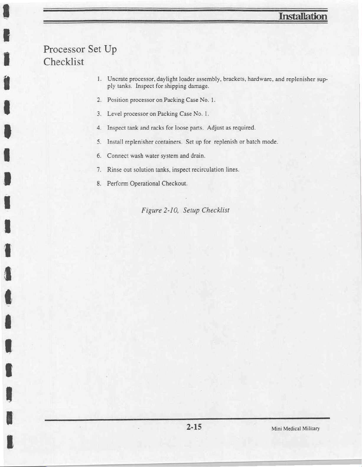
m5
на
Processor
Checklist
Set
Up
Uncrate
ply
tanks.
Position
Level
Inspect
Install
Connect
Rinse
Perform
processor,
Inspect
processor
processor
tank
replenisher
wash
out
solution
Operational
for
on
on
and racks
containers.
water
tanks,
Figure
daylight
shipping
Packing
Packing
for
loose
system
inspect
Checkout.
2-10,
loader
assembly,
damage.
Case
No.
Case
No.
parts.
Set
up
and
drain.
recirculation
Setup
Checklist
1.
1.
Adjust
for
replenish
brackets,
as
lines.
hardware,
required.
or
batch
and
mode.
replenisher
sup-
ююз
©
MB
©
MB
SB
em
2-15
Mini
Medical
Military
Page 37
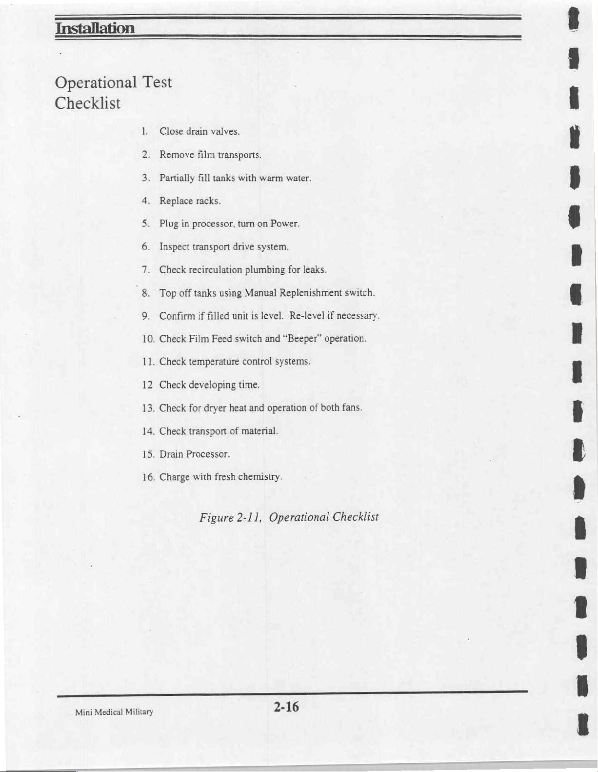
Installation
Operational
Checklist
Test
Close
Remove
Partially
Replace
Plug
Inspect
Check
Top
Confirm
.
Check
.
Check
drain
valves.
film
transports.
fill
tanks
racks.
in
processor,
transport
recirculation
off
tanks
using
if
filled
Film
Feed
temperature
with
turn on
drive
system.
plumbing
Manual
unit
is
switch
control
warm
water.
Power.
for
Replenishment
level.
Re-level
and
“Beeper”
systems.
leaks.
if
operation.
switch.
necessary.
Check
.
Check
.
Check
.
Drain
.
Charge
developing
for
dryer
heat
transport
Processor.
with
of
fresh
Figure
time.
and
operation
material.
chemistry.
2-11,
Operational
of
both
Checklist
fans.
Mini
Medical
Military
2-16
Page 38

D D
Installation
=
az
αυ
>
a
we
Notes:
M
€
O
=»
we
gp
e
e
2-17
a
Mini
Medical
Military
Page 39
Section
3
Operation
-
General
Index
-
Section
Section 2 -
Section 3 -
Section
Section 5 -
Section 6 -
1
4
-
-
Introduction
Installation
Operation
Maintenance
Service
Parts
/
Storage
AFP
Mini-Medical
X-Ray
Film
Military
Processor
Page 40
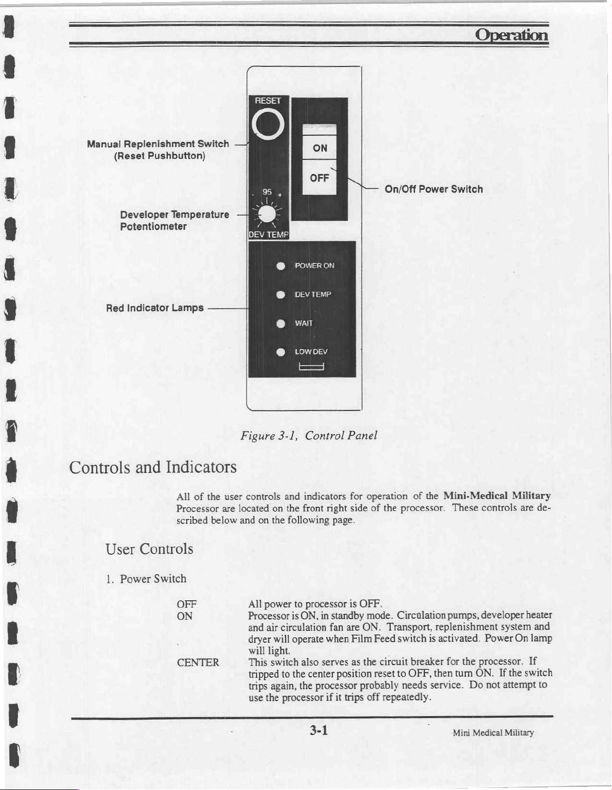
Manual
Red
Replenishment
(Reset
Pushbutton)
Developer
Potentiometer
Indicator
Switch
Temperature
Lamps
—
—
POWER
DEV
WAIT
LOW
ii
TEMP
DEV
ON
P—
On/Off
Power
Switch
Controls
User
1.
Power
and
Indicators
All
Processor
scribed
Controls
Switch
OFF
ON
CENTER
of
the
user
are
below
Figure
controls
located
and
on
All
power
Processor
and
air
dryer
will
light.
This
tripped
trips
use
the
3-1,
Control
and
indicators
on
the
front
the
following
to
processor
is
ON,
circulation
will
operate
switch
again,
also
to
the
center
the
processor
3-1
Panel
for
right
side
page.
is
in
standby
fan
are
when
Film
serves
as
position
processor
if
it
trips
operation
of
the
OFF.
mode.
ON.
Transport,
Feed
the
circuit
reset
probably
off
repeatedly.
of
the
Mini-Medical
processor.
Circulation
switch
breaker
to
OFF,
needs
pumps,
replenishment
is
activated.
for the
then
service.
These
turn
Do
Mini
Medical
ON.
Military
controls
developer
Power
processor.
not
are
system
On
If
the
switch
attempt
heater
lamp
If
Military
de-
and
to
Page 41
Operation
User
Controls,
(Cont'd)
2.
Manual
3.
4.
5.
Power
Dev.
Wait
ON/OFF
Temp.
Lamp
replenishment
Provides
turn
for
over
chemistry
Lamp
Lights
when
Lamp
Lights
day.
Illuminates
To
the
when
prevent
side
door
when
fogging
(Reset
Power
developer
of
manual
Film
of
the
Daylight
Switch)
operation
when
Switch
activity
heater
Feed
film,
of
is
ON.
is
ON.
switch
wait
until
Loader.
replenishment
levels
have
dropped.
Wait
for
light
is
activated
lamp
goes
and
OFF
pumps.
to
cycle
during
or
Use
to
“top
off”
OFF
before
Anti-Crystallization
beeper
sounds
first
before
tanks
use
cycle.
opening
or
to
each
6.
Low
7.
Drain
8.
Overflow
9
Top
Dev.
Valves
Cover
Lamp
ON
the
processor,
exists.
(3)
One
(1)
Lines
Drain
lines
Interlock
To
prevent
processor's
shuts
down.
down
bracket
Caution:
overridden.
indicates
the
each
to
from
Switch
accidental
dryer
This
provided
DO
NOT
that
developer
developer
drain
the
Developer,
developer,
injury
cover.
interlock
under
attempt
heat
fix & wash
from
If
the
dryer
may
be
the
feed
to
process
is
too
low
function
Fixer,
overflow
moving
parts, a safety
cover
overridden
tray.
film
for
is
turned
Wash
is
removed,
in
this
safe
operation.
OFF
tanks
ports.
for
service
unit
To
when
a
and
recirculation
switch
when
the
processor
use
only
the
is
interlock
prevent
low
interlocked
by
damage
level
condition
pumps.
with
automatically
using
the
is
to
the
hold
Mini
Medical
Military
3-2
Page 42

Operation
Loading
Chemicals
Always
normal
With
the
described
WARNING:
mixing,
taminate
To
prevent
carefully.
1)
Close
processor.
2)
If
not
3)
Cover
from
accidental
ppm)
is
processor
flushed
begin
with a clean
course
of
installation
developer
below:
Read
using and
the
developer
and/or
disposing
chemical
the
tank
drain
already
the
done,
developer
splashes
sufficient
first
out
to
so
that
before
the
processor.
or
fixer
and
heed
safety
of
solution.
splashing
remove
tank
and
valves
the
with a sheet
of
fixer.
contaminate
any
splashes
addition
The
processor
maintenance.
tank
cleaned
precautions
processing
the
on
the
three
solutions.
risk
of
ends
of
film
of
Caution:
the
developer
into
the
of
developer.
should
and
drained,
given
by
add
č
the
Do
contamination
the
hoses
coming
transports
film,
Minute
paper
amounts
and
or
solution.
developer
have been
processing
chemical
not
allow
follow
from
set
aside.
other
material
of
Always
tank
can
cleaned
chemicals
manufacturer
the
fixer
these
instructions
the
front
to
protect
fixer
chemical
add
fixer
be
wiped
in
to
of
to
up
the
as
in
con-
the
it
(5
the
or
4)
Carefully
plastic
bottom).
insure
5)
accidental
6)
tank
side
7)
fill
flow.
8)
or
that
worm
9)
supply
fill
mark
Do
that
no
Cover
the
splashes
Carefully pour
the
to
up
(4"
from
Carefully
located
mark
Replace
overflow.
tank
main
the
gears
Attach
containers.
pour
about
located
Not
attempt
fixer
has
fixer
tank
of
about
plastic
bottom).
about
pour
similarly
transports.
film
the
Check
drive gears
main
the
on
screw
the
1.5
gallons
on
the
inside
to
fill
the
splashed
or
with a sheet
developer.
1.5
gallons
located
mark
fill
Do
Not
attempt
gallons
1.5
the
to
Lower
correct
for
the
on
shaft.
drive
on the
caps
of
fixer
of
the
tank
to
the
spilled
of
other
into
film
or
of
developer
the
on
to
fill
warm
of
two.
them
seating
transport
replenisher
drive
working
tank
wall
overflow.
it.
Wipe
paper,
working
inside
the
tank
into
water
attempt
Not
Do
the
into
locating
the
on
shafts
hoses
solution
on
the
Inspect
up
or
or
other
material,
solution
tank
the
of
to
the
wash
the
to
slowly
tanks
pins
properly
are
fittings on
the
to
into
the
fix
non-drive
the
developer
flush
out
to
into
on
wall
overflow.
tank
tank
the
fill
prevent
to
driveshaft.
and
engaged
tank
side
if
fixer
protect
the
developer
non-drive
the
the
to
up
to
replenisher
the
up
to
the
(4"
from
tank
to
is
found.
it
from
plastic
over-
the
splashing
Verify
the
with
Power
the
Turn
10)
replenishment
drain
tubes.
pumps
Switch-ON.
developer,
the
until
3-3
Operate
Manual
the
fixer
and
Replenishment
water
wash
switch
the
in
seen
are
Mini
Medical Military
the
run
to
overflow
Page 43
Operation
Daily
Processor
Fill
Start
Up
Wash
The
daily
start
up
ON,
Tank
1)
Close
the
wash
into
the
wash
tank
from
the
bottom
overflow.
2)
Switch
mode
3)
Allow
cycle
Caution:
ing
correctly.
without
Caution: A kink
the
processor.
the
and
run
the
OFF).
Always
dips
Power
for
developer
Check
All
or
procedure
tank
up
on
the
Switch
approximately 4 minutes.
for
inspect
drain
loops
that
or
twist
is
as
drain
valve.
to
the
plastic
non-drive
to
the
to
warm
leaks
around
to
see
that
tubes
must
can
cause
in a drain
follows:
Carefully
fill
side
of
ON
up
to
all
all
be
airlocks.
tube
pour
mark
located
the
unit..
position.
operating
hose
drain
routed
can
The
fittings.
tubes
in a continuously
cause a serious
about
1.5
on
the
inside
Do
Not
attempt
processor
temperature
are
properly
chemical
gallons
will
(Dev
positioned
of
of
the
to
fill
start
Temp
downward
or
warm
tank,
the
tank
in
the
process
light
and
drain-
direction,
water
spill
water
4"
up
to
the
will
in
Check
Fixer
and
Levels
Check
Dev
eloper,
Wash
If
adequate
plenishment
Drive
With
mesh
freely,
Bull's
necessary
Water
not
previously
solution.
the
Power
properly
without
Eye
done,
Prepare
switch,
level
top
Switch
and
turn
interference
provided
check
the
fresh
off
each
in
the
ON
without
or
to
ensure
developer,
replenisher
tank
with
position,
binding.
binding.
Replace
that
fix
and
if
necessary
chemistry
check
all
Make
sure
the
the
machine
wash
tanks
and using
to
the
turning
the
transport
lower
is
level.
to
see
overflow
drive
gears
rollers
front
cover
Make
that
they
contain
the
Manual
port.
to
see
that
are
turning
and
check
adjustments
Re-
they
the
as
Mini
Medical
Military
Page 44

Processing
Daylight
Film
Loader
The
front
arms
(located
box. A similar
cassettes
A typical
Ensure
of
the
the
cassette
tightly
recommended
the
Film
pressing
disengage
bending
the
film
Caution:
light
Operation
of
the
Daylight
are
inserted.
in
the
front
door-is located
are
fed
into
cassette
that
the
Film
loader.
shut.
fog
Insert
recess
Put
jewelry,
Storage
the
stainless
the
two
it
to
the
is
in
position,
Close
Film
damage
Box,
right
Film
left
corner
and
loading
Storage
film
in
the
bottom
arms
through
etc.,
located
steel
(2)
steel
and
close
Storage
to
stored
Loader
may
be
loaded
of
on
removed
sequence
Box
door
cassette
of
the
be
removed
in
the
plate
inward
snaps.
place
it
the
cassette.
Box
film.
has
two
(2)
into
the
loader),
the
right side
from
the
loader
is
as
follows:
is
securely
(14" X 17"
the
loader
sleeved
holes
first)
left
rear side
on
the
Carefully
between
door
the
before
arm
holes
and
accessed
by
opening
of
through
shut.
maximum
and
close
in
front
and
open
of
the
right side
pull a film
two
halves
removing
through
from
the
door
the
loader.
this
Open
the
size
),
the
door.
of
the
the
cassette.
Daylight
of
the
box
towards
of
the
arms
which
the
Film
on
Boxes
door.
door
on
hinged
Make
loader
Open
Loader
(See
you
open
cassette.
from
loader
the
operator's
Storage
the
front
of
film
the
right
side
down
sure
the
(Note:
the
Assembly
Figure
while
to
Box
of
the
and
side
into
door
is
It
is
door
to
by
2-5)
to
gently
When
avoid
Open
the
After
exposure,
tom
of
the
loader
sleeves
it
90
degrees
Caution:
placed
film
The
sor.
film
cassette
against
sensors
machine
Once
and
ro)
1)
has
cleared
After
the
By
mode
door
on
the
return
Daylight
and
open
and
bend
When
feeding
the
is
activated
will
go
the
film
is
reload
goes
processor
awaiting
ent
the
the
이
and
entry
the
right
side
the
cassette
Loader
Assembly
the
film
it
forward
film
right
or
left
and
into
the
accepted
cassette.
right
GET
the
rollers
completes
next
film.
of
loader
cassette.
into
sizes 8" X 10"
inside
to
maintain a straight
process
and
is
Do
side
u
and
its
processing
and
hinged
and
Pull
the
edge
mode
feeding
remov
of
the
i
indicating
is
safe
remove
edge
close
the
film
or
of
and
into
"WAIT"
from
cycle
down
feed
the
potential
the
to
the
the
door
film
upward
tray.
smaller,
feed
tray
film
begin
to
the
processor,
loader
or
remove
that
the
it
will
automatically
cassette
cassette
tightly.
from
make
sure
to
ensure
path.
pull
the
it
is
the
locate
trailing
light
fogging.
to
be
recess
Put
the
film
safe
Film
edge
into
exposed.
in
the
arms
into
cassette,
that
that
to
Storage
return
the
one
the
let
go
of
to
the
rotate
film
of
proces-
of
Stand-
bot-
the
is
the
the
t
Bo:
r
film
3-5
Mini
Medical
Military
Page 45

Shutdown
Drain
Clean
Guides & Rollers
Wipe
and
Wash
Daily
Basic
work,
Tank
Open
tank
Top
Cover,
Using a separate
transport.
Caution:
contaminate
off
Processor
Thoroughly
a
damp
prevent
Cleaning
care
of
the
allow
15
the
wash
with
fresh
Do
the
wipe
cloth.
condensation
processor
minutes
tank
warm
not
drain
wet
use
to
water,
cloth
the
developer.
the
inside
Replace
the
of
chemistry
goes
clean
valve
then
for
developer
same
and
top
and
cover,
hand-in-hand
the
processor
allow
the
close
the
drain
and
cloth
for
fixer
outside
surfaces
leaving a slight
vapors.
with
its
as
described
wash
water
valve.
fixer,
wipe
and
developer
of
the
operation.
below.
to
drain.
the
exposed
transports.
top
cover
opening
over
Following
Rinse
out
rollers
and
side
the
drive
each
the
on
Fixer
panels
shaft
day’s
wash
each
may
with
to
Mini
Medical
Military
Page 46

Quality
Control
Developer
Fixer
A
good
quality control
It is
recommended
maintained
Following
your
tance.
Developer
monitoring
Exhausted
appear
processing.
Exhausted
quently
to
are
film
and
activity
of
fixer
immediately
fixer
prevent
program
that a quality
assure
the
some
suggestions
chemistry
can
be
your
production
will
usually
after
can
also
proper
drying
is
essential
control
quality
of
your
for
technical
representative
monitored
work.
result
in
processing
contribute
from
taking
program
output.
those
by
use
dark
or
may
to
transport
place,
to
the
production
for the
areas
that
for
additional
of
pre-exposed
streaks
not
appear
problems
in
resulting
processor
should
control
your
film’s
until
hours
such
in
sticky
of
quality
be
established
be
monitored.
information
strips
emulsion
or
even
as
jams
film
radiographs.
and
Contact
and
assis-
or
by
careful
that
may
days
after
and
will
fre-
surfaces.
The
general
istry.
When
immerse
on
the
limit,
NOTE:
processor.
Replenishment
Manual
(Reset
Pushbutton
Switch)
The
depressed,
it
a
Medical
water
ishment
Manual
released,
is
process
quality
pH
is
too
pH
test
strip.
If
discard
the
Only
terminal-type
Do
Pushbutton
including
the
cycle,
Military
with
tanks
the
by
of
your
fixer
high,
films
may
strips
in
the
fixer
the
pH
rises
toward
old
fixer
and
silver
not
try
to
reuse
(Reset
developer,
the
machine
after
Processor
fresh
timing
it
which
consists
working
replenishment
can
be
jam
in
and
read
the
replace
recovery
fixer
after
Switch)
fixer
functions
returns
to
of
solution
system,
triggered
determined
the
wash
tank
its
pH
value
chemical
with
manufacturer's
fresh
chemicals.
systems
silver
has
activates
wash
and
initiated
are
standby.
“topping”
start
the
at
by
by
monitoring
and
the
from
are
recommended
been
removed.
functions
all
replenishment
water
the
and
Manual
off
of
film
replenishment
developer,
the
shift
each
presence.
the
dryer.
the
resultant
recommended
the
in
machine
and
pH
of
the
To
determine
color
for
use
with
machine
pumps.
through
goes
the
in
and
fixer
automatic
chem-
pH,
change
upper
this
when
When
Mini-
wash
replen-
3-7
Mini
Medical
Military
Page 47

Operation
.
Quality
-
(Cont'd)
Replenishment
(Cont'd)
Automatic
Control
Automatic
which,
cian
film
replenishment
in
turn,
actuates
set
adjustments,
feeding
to
replenish
is
accomplished
the
electronic
the
developer,
the
working
by
the
replenishment
fixer
and
wash
solution
in
film
tripping
circuitry.
pumps
their
respective
will
cycle
the
Film
Feed
Depending
on
and
tanks.
Switch
on
techni-
off
during
Manual
1)
2)
3)
NOTE:
are
switch
the
ishment.
Replenishment
To
top
off
To
restore
To
compensate
Chemistry
processing.
to
add
replenishment
the
tanks
chemical
for a basic
requirements
If
you
fresh
chemistry,
control
may
be
required
at
start-up.
strength
find
after
several
under-replenishment
vary
by
that
you
must
it
is
recommended
circuits
as
required
for
one
of
days
the
type
of
frequently
that
to
allow
three
reasons.
of
shut
down.
condition.
work
and
average
use
the
you
have
for
adequate
They
(See
NOTE
Manual
your
technician
automatic
are:
below)
size
of
films
Replenishment
you
adjust
replen-
Mini
Medical
Military
3-8
Page 48
Checklists
Start-up
Operation
Shutdown
for
Daily
.
Check
Top
off
.
Power
allow
.
Clean
.
Check
.
Feed
.
Wait
W
Daylight
Film
Storage
and
Daily
Use
solution
processing
Switch
15-30
feed
developer
film
until
to
minutes
tray,
to
start
Wait
Loader
Box
Cleaning
levels.
tanks
and
ON,
check
warm
receiving
activity,
processing
Lamp
goes
or
opening
from
the
fill
wash
drive
up.
bin.
fixer
pH.
cycle.
out
or
the
side
Loader.
tank.
gears
Tone
door
for
meshing;
sounds
on
the
before
removing
Daylight
Loader
arms
from
or
removing
the
the
.
Switch
.
Drain
-
Clean:
a)
b)
Wipe
.
panels.
Leave
.
tion.
NOTE:
power
and
rinse
Roller
surfaces,
Splashes
outside
cover
top
Duplicate
off.
wash
transport
from
inside
surfaces
and
these
tank.
Close
and
top
cover.
processor,
the
of
Daylight
checklists
Loader
valve.
tank
post
and
area.
inside
door
side
them
surfaces
slightly
near
of
open
processor.
the
feed
to
and
tray
prevent
side
both
condensa-
3-9
Mini
Medical Military
Page 49
Section
4
Maintenance
-
General
Section 1 -
Section 2 -
Section 3 -
Section 4 -
Section 5 -
Section 6 -
Index
Introduction
Installation
Operation
Maintenance / Storage
Service
Parts
/
Storage
-
AFP
Mini-Medical
X-Ray
Film
Military
Processor
Page 50
Maintenance
Maintenance
Cleaning
Program
Maintenance
operations,
has a set
quality
Records
Good
cessor.
formed
Figure
nance
Figure
Make
Cleaning
late
on
affect
routinely
maintenance
performance.
preventive
Keeping
when
4-1
is a Maintenance
intervals.
4-2
is a Maintenance
additional
is
the
processor
production
of
the
Mini-Medical
performed,
program,
maintenance
on-going
scheduled.
copies
most
and
important form
parts
they
and
output
Military
to
keep
with
is
essential
records
of
Schedule
Log
for
post
near
can
cause
quality.
Processor
the
processor
specific
operations
to
assure a long
maintenance
that
lists
tasks
keeping
the
of
monthly
processor.
maintenance.
corrosion
consists
operating
will
to
be
records
If
or
other
of
cleaning
correctly.
responsible
and
trouble
help
assure
performed
of
maintenance
chemicals
damage
are
and
The
for
maintenance
free
life
that
the
at
prescribed
allowed
which
may
adjustment
processor
of
the
pro-
work
is
per-
mainte-
performed.
to
accumu-
seriously
of
Perform
shutdown
Weekly
cleaning.
portation
Do
cleaning,
not
replace
daily
cleaning,
procedure.
should
Additional
and
storage.
items
as
outlined
take
about
cleaning
removed
schedule
for
on
the
thirty
daily
Maintenance
minutes
should
cleaning
be
performed
until
Schedule,
following
before
after
weekly
Figure
the
last
disassembly
cleanup
4-1,
as
shutdown
has
part
and
for
been
of
the
daily
trans-
com-
pleted.
abrasive
harsh
use
scrub
Never
pads
such
as
"'Scotchbrite"
Caution:
use
material
on
to
rollers.
Mini
processing
or
racks
clean
tanks.
Medical
Never
Military
4-1
Page 51

Maintenance
Daily
Weekly
NOTE:
DISASSEMBLY
THE
MONTHLY
FOR
Mini-Medical
Clean:
Developer
Top
Feed
Check:
Chemical
Replenisher
Processor
Clean:
Developer
Fix
Rack
Wash
Wash
Tank
MAINTENANCE
TRANSPORT
Rollers
Covers,
Tray,
Receiving
Levels
Level
Rack
Rack
Tank
Exteriors
Maintenance
Side
Panels
Bin
Levels
OR
STORAGE.
Military
SCHEDULE
Processor
Schedule
SHOULD
BE
PERFORMED
BEFORE
Monthly
Yearly
Or
Clean:
Developer
Replenishment
Fixer
Replenishment
Wash
Check:
Hose
Rack
Lubrication
After
Clean:
Developer
Check:
Drive
Drive
Lubrication
Tank,
Circulation
System
Tank,
Circulation
System
Tank,
Drain & Overflow
Clamps & Plumbing
Bearings
Points
Long
Term
& Fixer
Belt
Motor
Circulation
Brushes
Points
&
&
System
Storage
Pumps
|
Mini
Medical
Military
Figure
Maintenance
4-1,
4-2
Schedule
Page 52

Mini-Medical
Military
Maintenance
HRS | DATE
MONTHLY
9
10
11
12
13
14
15
16
17
18
19
20
1
22
23
24
25
26
27
28
29
30
31
Note:
it
Processor
1s
run
80
hours
or
more a week.
+
perform
maintenance
YEARLY
LUBRICATION
twice
MAINTENANCE
CLEAN
CLEAN
CLEAN
CHECK
CHECK
MAINTENANCE
CLEAN
CHECK
CHECK
CHECK
DRIVE
TRANSPORT
DRIVE
as
ohen.
Processor
Log
OPERATION
DEVELOPER
FIXER
SYSTEM
WASH
SYSTEM
HOSE
CLAMPS
LUBRICATION
FIX 8 WASH
DRIVE
BELT
MOTOR
BRUSHES
LUBRICATION
SHAFT
BRGS
BEARINGS
SHAFT
GEARS
1.
Duplicate
2.
Perform
3.
List
4.
Retain
*
Where
SYSTEM
DIAGRAM
PUMPS
DIAGRAM
(MONTHLY)
(MONTHLY)
(MONTHLY)
this
copy
to
operations
as
operating
hours
at
completed
log
applcanie
provide a supply
instructed
each operation
sheets
ot
log
in
Users
Manual
and
intial
for
continuing
history
sheets
Figure
4-2,
Maintenance
Log
Mini
Medical
Military
Page 53

Maintenance
Weekly
Cleaning
1)
Remove
tamination,
Clean
each
traces
of
NOTE:
non-metallic,
damage
2)
and
dry
3)
non-metallic
Caution:
rust
4)
5)
Soft
the
Inspect
baffles
while
Clean
to
form
Clean
Replace
the
developer,
wash
off
roller
over
adhesives.
scrub
scrub
roller
surface.
each
transport
are
properly
you
are
cleaning
the
outside
scrub
pad.
Never
the
on
the
dryer
all
removed
use
rollers
fixer
each
assembly
its
entire
pads,
such
pads such
thoroughly.
in
place.
the
surfaces
steel
wool
metallic
and
transports
and
wash
transport
separately
surface.
as
nylon
net
as
"Scotchbrite",
Verify
Carefully
rest
of
the
processor,
of
the
processing
on
any
part
parts
of
the
transport
and
parts
other
assemblies.
with
clean,
Use
isopropyl
over
sponge,
must
that
the
rollers turn
set
each
transport
tank,
using
of
the
processor
processor.
with a damp
parts.
lint-free
alcohol
work
not
be
warm
cloth
To
prevent
cloths
if
necessary
well
on
rollers.
used
on
rollers
freely
assembly
water
as
its
residue
and
wipe
chemical
and
warm
water.
to
remove
Metallic,
as
they
and
that
all
guides
aside
to
drain
with a sponge
may
cause
dry.
con-
or
will
and
or
Mini
Medical
Military
4-4
Page 54
Monthly
As
must
thoroughly
NOTE:
1)
tanks
fixer
sidual
the
chemistry
machine
Caution:
(54
2)
3)
The
developer
Dissolve
neutralizing
Cleaning
film
is
processed,
be
removed
This
Open
the
and
recirculation
and
wash
chemistry
solid
caps onto
and
is
When
degrees
Rinse
out
Systems
use
of
and
any
by
clean
the
cleaning
drain
valves,
replenishment
or
water
going
to
filling
C).
each
tank
Cleaning.
Developer
fixer
powdered
and
rinsing
or
Before
by-products
regular
developer,
cleaning.
will
replace
drain
systems
water
that
the
containers
and replace
continue
or
rinsing
and
then
Systems
system.
chemicals
steps
Transport
are
released
Every
fixer
and
wash
the
scheduled
and
dispose
to
drain
completely.
bottles,
may
to
be
Carefully
recommended
remain.
if
they
into
the
used.
the
close
and
Fixer
in
water
remove
are
machine
processor
the
drain
follow
into
month,
systems.
Weekly
of
the
used
the
Rinse
going
with
tanks,
valves
Systems
the
before
by
the
or
Storage
the
developer,
schedule
developer,
Remove
bottles
all
replenishment
to
be
the
and
Cleaners
two
hours
Cleaning
fixer
the
pickup
from
the
stored
or
transported.
appropriate
use
water
fill
the
wash
are
recommended
manufacturer's
adding
systems
to
the
tank.
cleaner
fix
and
wash
systems.
of
processor
due
on
the
same
and
wash
water.
tubes
from
machine
bottles
pickup
no
and
thoroughly.
tube
hotter
tank
with
pour
OR
assemblies
than
warm
for
instructions
Be
sure
and
to
accomplish
manufacturer.
These
downtime
date.
Allow
the
the
developer,
out
any
re-
Replace
Fill
with
fresh
if
the
120
degrees
water.
cleaning
the
precautions.
the
to
F
WARNING:
sor
with
its
4)
After
the
tank
with
fresh
the
transport
5)
Systems
blies.
For
additional
A)
Remove
Clean
B)
Appropriate
C)
"Scotchbrite"
has
been
Inspect
D)
Bearing
bearings
should
piates
Inspect
6)
brush
or
pad
and
drain.
Beware
access
panels
developer
warm
and
recirculation
cleaning
will
cleaning
the
transport
developer
the
Systems
type
cleaned.
transport
all
differs
wear
wear
to
tend
checked
be
empty
the
warm
and
of
all
rotating
removed.
and
fixer
systems
water
and
install
systems
remove
most,
and
from
fix
and
Cleaner
roller
on
pads
assembly
according
quickly
more
more
clean
to
tank
processing
water
gears,
inspection,
the
transports
may
surfaces.
end
the
to
frequently
the
are
the
transport
to
run
if
not
tank.
be
plates
solution
the
in
foreign
for
tank
shafts
thoroughly
for
all,
proceed
without
used
Rinse
fixer
for
interior.
and
drive
cleaned,
assemblies.
about
15
minutes
of
the
chemical
as
outlined
disassembling
remove
to
transport
the
wear.
for
which
in
solution,
wear.
matter
and,
Flush
belts
neutralized
Switch
residue
below:
stubborn
thoroughly
sure
Be
transport
the
fixer
the
necessary,
if
tank
the
when
operating
processor
as a final
from
them.
deposits.
rollers
the
used.
is
transport
use
warm
with
and
rinsed,
rinse.
the
transport
Never
after
turn
Since
end
soft
a
water
the
proces-
fill
ON
and
assem-
use
it
freely.
scrub
each
allow
Mini
Medical
Military
4-5
Page 55
Maintenance
on
Monthly
7)
pump
Caution:
8)
as
Annual
Cleaning
Check
Refer
indicated.
for
the
leaks.
Do
to
or
hose
clamps
Secure
not
over-tighten
Figure
Be
4-2,
sure
to
Maintenance
Once a year
cleaning,
1)
Inspect
sively
2)
Refer
drive
3)
Refer
Developer
additional
or
perform
the
worn
or
to
Service
belt.
to
Service
pumps
servicing.
Before
on
the
as
necessary.
clamps.
Maintenance
clean
off
or
After
after
extended
the
following
drive gears
damaged.
Procedure
Procedure
are
usually
Transport
developer,
Log
all
old
90
(90
on
each
5-2.
cleaned
fixer
This
can
and
Figure
lubricants
Day
day
plus)
tasks
on
the
transport
5-1.
Inspect,
Inspect
adequately
or
Storage
and
wash
cause
leakage
4-3,
Lubrication
and
any
Plus
storage
Storage
periods
processor:
assembly
and
adjust
and
clean
by
pumps
excessive
the
systems
and
or
damage
and
and replace
or
replace
fixer
and
(Cont'd)
the
base
of
each
to
the
pump
Points
new
and
lubricate
lubricants.
Periods
following a routine
any
gears
that
are
if
necessary,
wash
circulation
cleaning
and
do
not
heads.
monthly
exces-
the
main
pumps.
require
Special
Long
Term
4)
Refer
to
Service
Procedure
pumps.
5)
Refer
to
Figure
as
indicated.
Be
sure
to
clean
Maintenance
4-2,
off
all
Notes
Storage & Inspection
be
processor
The
tioning
from
to
or
precipitation
calibration
Certain
projected
a
time
interval
These
parts
Item
may
temperature
other
by
other
or
life
shelf
and
are
listed
items,
replaced
elastomer
for
Location
5-3.
Maintenance
old
lubricants
and
stored
Information
indefinitely,
controls.
waterproof
settings
tarpaulin
are
specifically
months.
60
if
necessary.
below:
Inspect
Log
and
and
and any
as
Outdoor
or
required
during
O-rings
should
They
clean
the
Figure
4-3,
excessive
for
shipped,
storage
other
and
indoors
would
comparable
storage.
replenishment
examined
be
Qty\Unit
developer
and
Lubrication
new
lubricants.
without
require
covering.
pump
loss
for
fixer
replenishment
Points
and
requiring
be
units
the
No adjustment
poppet
resiliency
of
P/N
AFP
lubricate
condi-
air
protected
valves
have
this
at
O-Ring
O-Ring
O-Ring
Poppet
Mini
Medical
Military
Valve
Dev.
Chemical
Chemical
Chemical
Recirc.
Recirc.
Pump
Pump
Replen.
Pump
Sensor
Temp
2
8
2
2
0000045805
0000045822
0000045825
0000083915
4-6
Page 56

Section
Service
-
General
Index
5
-
Section 1 -
Section 2 -
Section 3 -
Section 4 -
Section 5 -
Section 6 -
Introduction
Installation
Operation
Maintenance / Storage
Service
Parts
AFP
Mini-Medical
X-Ray
Film
Military
Processor
Page 57

WARNING:
any
electrical
adjustment
a
qualified
technician
technician.
Never
attempt
troubleshooting,
or
service
electrician,
or
factory
trained
to
perform
unless
you
electronics
service
are
Page 58
Content
This
section
Medical
contains
Military
information
Processor.
on
trouble-shooting
and
repairing
the
AFP
Mini-
Always
fore
Even
plain
consult
calling a service
if
you
the
problem
WARNING:
with
the
power
several
Following
repair
Also
applicable
and
NOTE:
event
Attempting
exchange
points.
the
procedures
in
this
schematics
equipped
The
of a component
credit
the
Troubleshooting
representative.
do
not
plan
to
to a service
Be
extremely
on.
Dangerous,
Troubleshooting
that
may
be
section
is a description
and a wiring
for
electronics
circuit
cards
in
failure,
to
repair
them
could
value
that
some
Chart
before
service
the
processor
representative.
careful
when
potentially
Charts
required
of
are
to
the
diagram.
trouble-shooting
lethal,
instructions
keep
control
These
trouble-shooting
this
processor
should
invalidate
cards
are
be
replaced.
any
may
have.
not
attempting
yourself,
electrical
the
processor
electronics
will
to
trace
failures
considered
remaining
service
the
chart
or
servicing
voltages
for
performing
functioning.
enable
in
field
warranty,
or
repair,
will
help
the
are
adjustment
in
the
processor,
users
who
the
electronics.
repairable
or
may
or
be-
you
ex-
processor
present
at
and
with
are
trained
and
in
the
cancel
tae
Troubleshooting
The
on
diminishing
right-hand
Test
for
Equipment
Service
and
Repair
Multimeter,
Oscilloscope,
Portable
Portable
Tool
Dryer
Troubleshooting
symptom,
under
left,
the
of
order
column,
and
Tool
Kit
Digital
Dual
Densitometer
Sensitometer
Kit,
Medical
Cover
Equipment.
Hold-Down
Charts
are
problem
a
likelihood,
Remedy,
provides
List
Trace
Storage
Bracket
divided
are
into
that
Probable
the
three
sounds
corrective
Required
Repairman
5-1
columns.
yours.
like
Causes
action(s)
for
for
To
use
either
middle
the
In
symptom.
a
such
probable
each
Mini
Medical Military
chart.
find
column,
The
cause.
in
Page 59
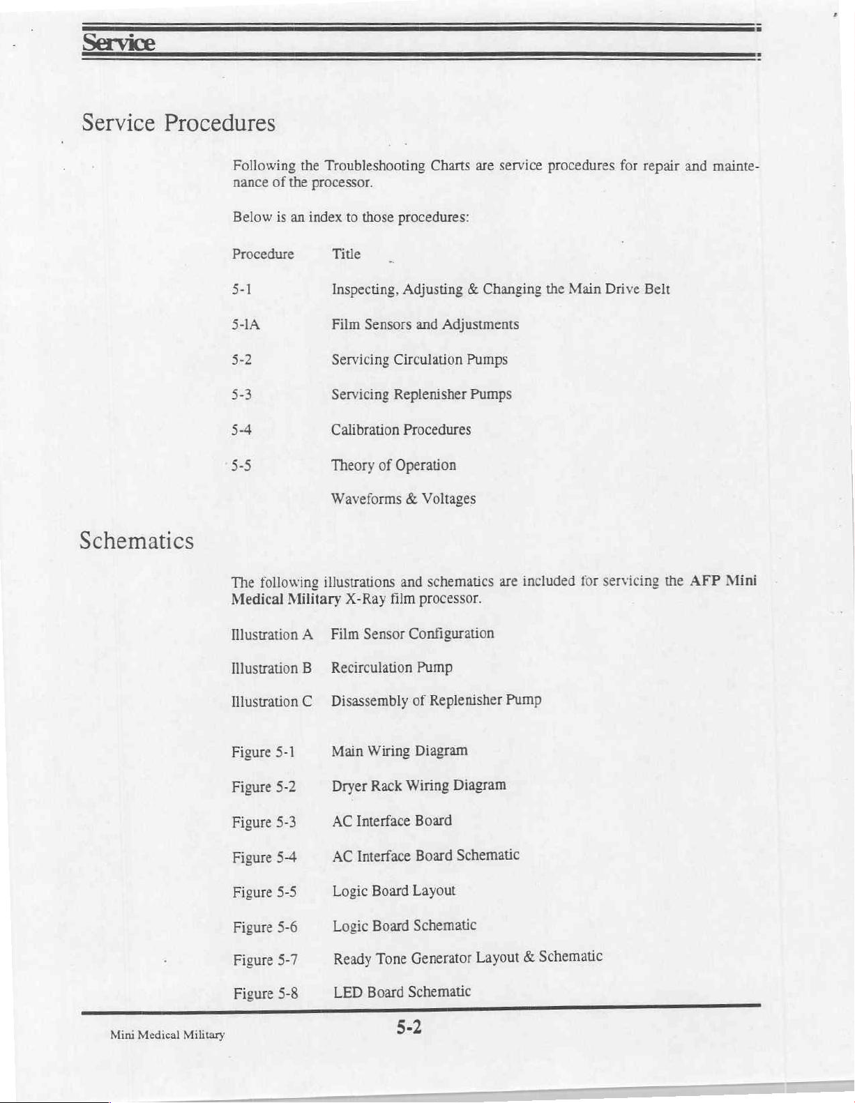
Service
Service
Procedures
Following
nance
Below
Procedure
5-1
of
is
the
an
the
Troubleshooting
processor.
index
to
those
procedures:
Title
Inspecting,
Film
Servicing
Servicing
Calibration
Theory
Waveforms & Voltages
Adjusting & Changing
Sensors
Circulation
Replenisher
Procedures
of
Operation
Charts
and
Adjustments
Pumps
are
service
Pumps
procedures
the
Main
Drive
for
repair
and
Belt
mainte-
Schematics
The
following
Medical
Illustration
Illustration
Illustration
Figure
Figure
Figure
Figure
Figure
Figure
Military
A
B
C
5-1
5-2
5-3
5-4
5-5
5-6
illustrations
X-Ray
Film
Recirculation
Disassembly
Main
Dryer
AC
Interface
AC
Interface
Logic
Logic
and
film
Sensor
Wiring
Rack
Board
Board
Configuration
Wiring
schematics
processor.
Pump
of
Replenisher
Diagram
Diagram
Board
Board
Schematic
Layout
Schematic
are
included
Pump
for
servicing
the
AFP
Mini
Mini
Medical
Military
Figure
Figure
5-7
5-8
Ready
LED
Tone
Board
5-2
Generator
Schematic
Layout
Schematic
&
Page 60

Troubleshooting
Processor
Symptom
1.
Developing
constant.
2.
Solution
too
high.
3.
Solution
too
low.
4.
Dryer
low.
5.
Dryer
high.
6.
Film
temperature
temperature
jams.
Problems
time
not
temperature
temperature
too
too
Probable
A.
Excessive
B.
Solution
A.
Temperature
B.
Shorted
C.
Defective
(Open)
D.
Logic
A.
Heater
B.
Heater
C.
Temperature
D.
Shorted
E.
Logic
A.
Failed
B.
Open
C.
Shorted
A.
Open
B.
Blower
C.
Logic
A.
Film
not
B.
Improper
too
high,
fixer
replenisher.
Cause
load
on
drive
motor.
levels
heater
low.
control
setting
triac.
temperature
sensor.
moved.
failure.
failed
triac
failed.
temperature
failure
heating
overtemp
temperature
temperature
failure.
(Open)
control
setting
sensor.
element.
switch
sensor.
sensor.
on
dryer.
moved.
failure. C.
fed
in
squarely.
fixing,
or
improperly
fixer
too
mixed
old,
pH
fixer
A.
seated
B.
required.
A.
B.
C.
sensor.
D.
A.
B.
C.
D.
E.
A.
B.
Inspect
running,
C.
A.
B.
A.
leading
rollers.
B.
above
or
fresh.
instructions
Remedy
Check
Add
Restore
Replace
Replace
Replace
Replace
Replace
Restore
Replace
Replace
Replace
Will
Replace
Replace
Replace
Replace
Feed
Check
that
and
turn freely.
chemicals
reset
for
cause;
dirt
film
edge
pH.
5.0,
dump
Follow
racks
are
as
correct
heater
temperature
logic
setting.
triac.
board.
heater.
heater
correct
sensor.
logic
element.
triac.
setting.
board.
when
cool.
fan
not
build-up,
etc.
sensor
sensor.
blower.
logic
board.
in
carefully,
parallel
the
exactly.
If
pH
and
mfg's
to
is
mix
Mini
Medical
Military
Page 61

—
==:
Service
Troubleshooting
Processor
Continued
Symptom
7.
Films overlap
become
transport.
8.
curled
9.
10.
emulsion.
skewed
Filmis
tacky,
when
Dirt
particles
Scratches
Problems,
or A.
during
wetor
leaving
dryer.
on film.
on
film
Probable
Bound
Rack
Missing
Improper
A.
Dryer
B.
A.
Foreign
squeegee
B.
Algae
C.
Foreign
roller(s).
A.
Dirt
Chemicals
B.
of
top
C.
Dirt
rollers.
D.
Roller
E.
Dirty
rollers
end
temperature
particles
rollers.
deposits
particles
on
feed
fiml
guides.
or
silver
in
feed
Cause
plate
bearings
rack
springs.
fixing.
too
in
dryer
on
film.
on
rollers
crystallized
accumulation
rack
not
turning.
tray
surface.
worn.
low.
or
on
squeegee
underside
on
on
Remedy
A.
Clean
check
binding.
B.
Replace
C.
Replace
A.
See
B.
Check
operation.
A.
Run
sheets
B.
Clean
racks
brush
Drain
night.
C.
Clean
roller(s).
A.
Clean
B.
Clean
C.
Clean
nylon
water,
systems
developer
systems
racks.
D.
operation;
required.
E.
Clean
for
5B.
several
of
unexposed
with
and
wash
scrub
or
developer
cleaner
cleaner
Check
each
causes
dryer
wash
nylon
warm
squeegee
feed
film
rollers
racks/fixer
all
repair
feed
roller;
of
bearings.
springs.
for
proper
outdated
film.
tanks
&
scrub
water.
tank
each
rollers.
guides.
using
pad and
warm
for
for
fix
rollers
for
as
tray.
a
Mini
Medical
Military
Page 62

=
Troubleshooting
ls
—
Service
Processor
Continued
Symptom
Increase
11.
density.
Problems,
image
in
Probable
is
Film
A.
B.
Developer
C.
Excessive
mechanical
D.
New
developer
E.
Developer
haywire,
Cause
exposed.
over
temperature
developing
binding.
improperly
temperature
too
high
time
due
to
mixed.
completely
Remedy
Coordinate
A.
developing
with
B.
Have
service
adjust
temperature.
C.
D.
following
instructions
E.
temperature.
developer
See
symptom
Dump
and
mfg's
Check
solution
exactly.
exposure
time.
technician
1.
mix
fresh
12.
Decrease
density.
13.
Over
14.
No
in
image
replenishing.
functions.
A.
Film
is
under
B.
Developer
exhausted.
C.
Developer
D.
Developer
E.
New
developer
A.
Shorted
B.
Shorted
switch.
C.
Pendulum
the
up
position.
D.
Logic
A.
Interupter
B.
Interupter
failure.
exposed.
under replenished
temperature
time
too
too
short.
improperly
film
presence
manual
magnet
switch
switch
switch.
replenishment
weak
or
not
activated.
defective.
or B.
low
mixed.
stuck
in
A.
Coordinate
with
developing
Change
Check
C.
D.
low
E.
mix
A.
B.
С.
replenishment
See
Symptom
Check
level.
Dump
fresh.
Replace
Replace
Clean
or
pendulum.
D.
Replace
A.
Put
top
B.
Replace
exposure
time.
developer.
3.
developer
developer
and
switch.
switch.
replace
logic
board.
cover
in
place.
switch.
rates.
for
Note:
The
either
utilizing
Jumping
interupter
the
the
pins
hold
on
switch
down
J-14
on
may
tool
the
5-5
be
bypassed
(P/N
logic
board
for
troubleshooting
0000021801)
is
an
alternate
to
keep
method.
the
Mini
Medical
purposes
switch
Military
only
by
activated.
Page 63
Service
Service
Inspecting,
the
Inspection
Adjustment
Procedure
Adjusting & Changing
Main
Drive
The
main
with
The
belt
conditions
1)
Excessive
2)
Frayed
3)
Missing
5-1
Belt
drive
normal
should
are
or
or
belt
use.
be
found:
slack
badly
damaged
requires
inspected
that
worn
only
cannot
edges.
drive
minimal
yearly.
be
corrected.
lugs
on
maintenance
Replacement
the
belt
surface.
and
is
indicated
normally
if
any
lasts
of
the
many
years
following
Adjusting
Adjust
1)
2)
the
3)
4)
5)
Replacement
The
1)
2)
3)
processor.
slots
in
the
following
Unplug
Loosen
processor,
Slide
Tighten
If
all
the
the
the
motor
the
slack
below
cannot
following
Unplug
Remove
.Loosen
the
all
the
Move
to
tension
processor from
motor
four
to
four
screws.
procedure
processor
four
four
the
manner:
the
dryer.
make
removed,
be
racks
drive
motor
the
mounting
the
to
is
from
(dev,
motor
to
drive
its
power
plate
belt
just
the
followed
be
its
power
wash
fix,
mounting
remove
belt
outlet.
snug.
belt
outlet.
the
are
provided
screws.
excessively
worn
is
replacing
when
dryer)
&
attaching
plate
belt.
drive
in
These
carefully
and
the
motor
accessible
are
and
worn
a
set
screws
mounting
on
should
drive
aside.
the
on
the
replaced.
be
belt:
rear of
plate.
back
of
the
Mini
Medical
4)
Military
Remove
the
cotter
holding
pin
5-6
the
drive
belt
pulley
to
the
driveshaft.
Page 64
Service
Drive
Procedure
Belt
Replacement,
5)
Slide
the
end
6)
Install
7)
Adjust
5-1
the
of
the
the
the
Continued
driveshaft
driveshaft.
new
new
belt
belt
pulley
in
as
forward
the
reverse
described
far
enough
order.
above.
to
allow
removal
of
the
belt
around
Medical Military
5-7
Mini
Page 65

,
Service
Procedure
5-1A
Film
Sensors
The
form
three
magnetic
in
conjunction
Activation
the
sembly
Illustration A shows
and
Adjustments
Mini-Medical
of
two
hall-effect
inches
dual
in
pendulum
of
either
switch
is
P/N
from
with
arrangement
21876.
Military
the
assemblies
these
switch
the
processor
magnetic
iriner
sensors.
will
(The
part
vertical
digital
right
and
(P/N
21893),
put
the
is
to
accommodate
numbers
sensor
features
left
machine
configuration
dual
sensors
sides
located
into
smaller
given
above
(P/N
of
switch
the
the
film
21878)
feed
above
the
process
size
are
for 1 each
currently
sensing.
located
tray.
There
feed
mode.
films.
bein
This
is
approximately
are
now
tray,
that
are
The
purpose
The
feed
tray
of
the
parts.)
used.
in
the
two
used
as-
of
Mini
Medical Military
Illustration
Sensor
Film
adjustment.
need
not
1)
adapter;
tray
feed
2)
machine
the
machine
the
sensor
in
Adjustment:
Loosen
Locate
question
the
the
each
remains
the
into
until
A,
Film
However,
screw
sensors
sensor
standby.
in
process
it
does.
Sensor
These
should
each
on
may
upward
Raising
mode.
Configuration
adjusted
sensors
be
are
adjustment
bracket
small
moved
If
up
enough
close
either
does
this
required,
be
securing
down.
or
to
magnet
occur
not
factory
the
at
the
magnet
the
inserting
by
in
and
follow
sensors
opposing
a
either
normally
procedure:
this
the
to
it
should
film
lower
case,
do
molded
that
so
put
the
Page 66
Section
Parts
-
General
Index
6
-
Section 1 -
Section 2 -
Section
Section 4 -
Section 5 -
Section 6 -
3-
Introduction
Installation
Operation
Maintenance / Storage
Service
Parts
AFP
Mini-Medical
X-Ray
Film
Military
Processor
Page 67

General
Item
1
2
3
4
5
6
7
8
9
10
11
12
13
14
15
16
17
18
19
20
21
22
23
24
25
26
27
28
29
30
31
32
Assembly
Part
Number
0000021
0000021
257-2
421-1
0000022025
0000084469-1
0000022029
0000022029-1
0000021700
0000086709-1
0000086709
801-049281
801-049291
801-049291-1
0000021801
0000021845
0000021846
0000021865
0000022003-1
0000021876-1
0000022142
0000044501
0000022053
0000037112
0000037283
0000080000
0000037051
0000046251-C
0000049004
9526062640
9527062640
9528062640
9902001201
9902001202
Description
Tank/Frame
Side
Cover
Cover,
Fan
Assembly,
Darkwall
Darkwall
Panel,
Water
Bottle, 1 Gal.
Assembly,
Assembly,
Assembly,
Int.
Front
Rear
2-Piece
listed
Foot,
Film
Feed
Level,
Wrench,
Manual
Switch/Circuit
Leveling
Interrupter
Elbow,
Ball
Tubing,
Tubing,
Tubing,
»Daylight
Film
Drain
Tank,
Switch
Top
Top
above)
Plastic,
Feed
Tray
Circular
Valve,
Box
Unit
(Not
Electronics,
Panel,
Foam
2.2
Replenisher
Developer
Fixer
Wash
Hold
Cover
Cover
Top
Cover
Modified,
Tray,
Cover
9/16" X 13mm
Replenishment/Reset
Breaker,
Foot
Switch
1/2"
Drain
1.D.
1/2"
1.D.
1/2"
I.D.
1/2"
Loader
Assembly
Shown)
Military
Daylight
Daylight
Seal
Gal.
(1
Pickup
Pickup
Pickup
down
Bull's
tool
Set
MM,
Military
Eye
(Not
Shown)
11/16"
X
11/16"
X
11/16"
X
Assembly
Loader,
Loader,
used/1
(2
(Not
(includes 2 covers
Military
(Not
(level
15
Amp
O.D.
O.D.
O.D.
Mil
Mil
spare)
ea
dev/fix)
Shown)
shown)
foot)
Switch
Clear
Red
Blue
No.
Used
SE
REO
2
total
4
total
a:
Ak
ris
rs
DO
Mini
Medical Military
Page 68

Introduction
This
section
Medical
corresponding
is
Military
lists
each.
an
illustrated
processor.
give
the
catalog
Illustrations
part
of
repair
number,
show
description
and
replacement
the
locations
and
parts
of
replaceable
quantity
per
Parts
for
the
parts
assembly
Mini-
and
for
How
When
Parts
Are
Ordering
Documentation
Listed
Most
parts
shown
repeated
description
Attaching
on
the
and
parts,
Parts
Give
the
part
model
Mini
and
serial
Medical
in
the
accompanying
quantity
when
listed,
number,
Military
description
number
Manual,
illustrations
of
the
are
of
the
are
parts
list(s).
parts.
shown
processor
P/N
below
and
quantity
0000061152
identified
The
the
with
list(s)
listing
required
for
which
the
reference
will
include
for
that
part
for
each
parts
are
needed.
numbers
the
part
or
assembly.
part.
Give
which
number,
also
are
the
Mini
6-I
Medical
Military
Page 69

Parts
*Note:
remoted
the
attached
Ball
to
valves
the
ends
hoses
are
of
Figure
6-1,
General
6-1
Assembly
Mini
Medical
Military
Page 70

Daylight
Item
1
2
3
4
5
6
7
8
9
10
11
12
13
14
15
16
17
18
19
20
21
Loader
Part
Assembly
Number
0000022023
0000022021-1
0000022032
0000022044
0000022026
0000022027-1
0000022027-2
000-01108-AW-R
0000022038
0000022039
0000022040
000-01116-BS-B
000-05400-AA-H
0000044760
0000044759
0000047806
0000022041
0000044773
0000045451
0000044043
0000048262
P/N
9902001201
Description
Box,
Daylight
Cover,
Hinge,
Shim,
Door,
Modified
Door
Sleeve,
Clamp
Clamp
Screw,
Ring,
Ring,
Thumb,
Hanger,
Shim,
Shim,
Eye
Nut,
Hanger,
Hinge,
Bolt,
Hex,
Arm
Load
Daylight
Hinge,
Outer
Inner
1/4-20 X 1/2"
Daylight
Load
Daylight
Daylight
1/4-20 X 1"
1/4-20
SST
Turnbuckle 4 RH/LH
Gate
Hook,
Catch
Door
Latch,
Latch,
Label,
Knob,
Stand-Off
5 In.
Spring
Door,
Southco,
Male
Caution:
Door
Assembly
97-60-320-11
Film
Loader
Box
Load
Load
or
right
Nylon
Box
Box
Left
No.
Used
1
1
1
1
2
2
2
12
1
1
1
2
2
2
2
2
2
1
1
1
2
Film
Item
1
2
3
4
5
6
7
8
9
10
11
12
13
Mini
Box
Medical
Assembly
Number
Part
0000022022
0000022021-2
0000022032
0000022044
0000022031
14083390002
0000044006
0000022045
0000022046
0000047833-1
0000022030
0000022049
0000022048
Military
P/N
9902001202
Description
Film
Cover,
Hinge,
Shim,
Divider,
Fastener,
Storage
Door,
Modified
Door
Film
Handle,
Latch
Latch
Spring,
Seal,
Mount,
Retainer,
Case
Bar,
Catch,
Compression,
Film
Angle,
Film
6-2
Box
Film
Hinge,
Box,
Black
F1-10-106-12
Box
Film
Film
Storage
Film
Box
Box
MMed
MMed
Box
Modified
Box
Box
Military
Military
Military
(Not
Door
(Not
Shown)
(Not
Shown)
Shown)
No.
Used
1
1
1
1
1
4
1
1
2
2
1
1
1
Page 71

HD:
13702)
(A
dB
c
a“
Illustration
B,
Film
6-3
Box
Assembly
Mini
Medical
Military
Page 72
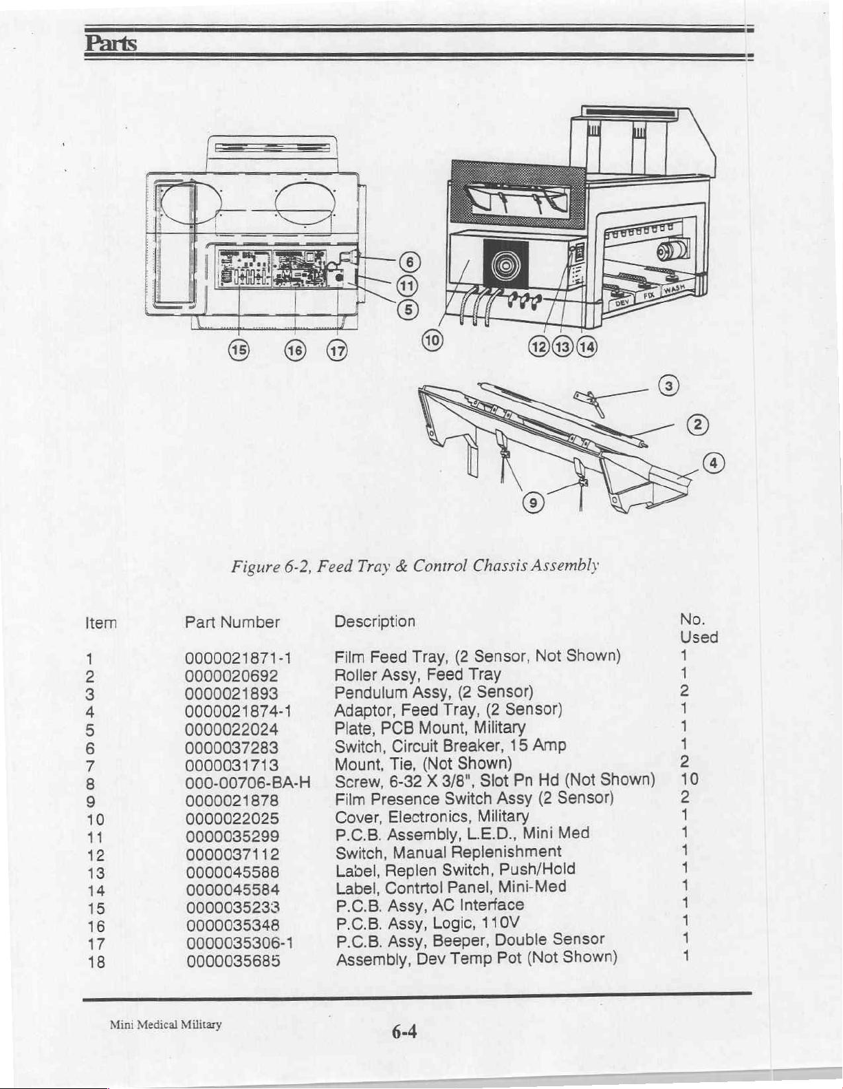
Figure
6-2,
Feed
Tray & Control
Chassis
Assembly
Item
1
2
3
4
5
6
7
8
9
10
11
12
13
14
15
16
17
18
Part
Number
0000021871-1
0000020692
0000021893
0000021874-1
0000022024
0000037283
0000031713
000-00706-BA-H
0000021878
0000022025
0000035299
0000037112
0000045588
0000045584
0000035233
0000035348
0000035306-1
0000035685
Description
Film
Feed
Tray,
Roller
Pendulum
Adaptor,
Plate,
Switch,
Mount,
Screw,
Film
Cover,
P.C.B.
Switch,
Label,
Label,
P.C.B.
P.C.B.
P.C.B.
Assembly,
Assy,
Assy,
Feed
PCB
Mount,
Circuit
Tie,
6-32
Presence
Electronics,
Assembly,
Manual
Replen
Contrtol
Assy,
Assy,
Assy,
Dev
(2
Sensor,
Feed
(Not
X
Tray
(2
Sensor)
Tray,
Breaker,
3/8",
Switch,
AC
Logic,
Beeper,
(2
Military
Shown)
Slot
Switch
Replenishment
Panel,
Temp
Assy
Military
L.E.D.,
Interface
110V
Double
Pot
Not
Sensor)
15
Amp
Hd
Pn
(2
Sensor)
Med
Mini
Push/Hold
Mini-Med
Sensor
(Not
Shown)
Shown)
(Not
Shown)
6
gi
5
A
SEU)
Data
DO
ANSA
nad
A
hı
a
Mini
Medical
Military
6-4
Page 73
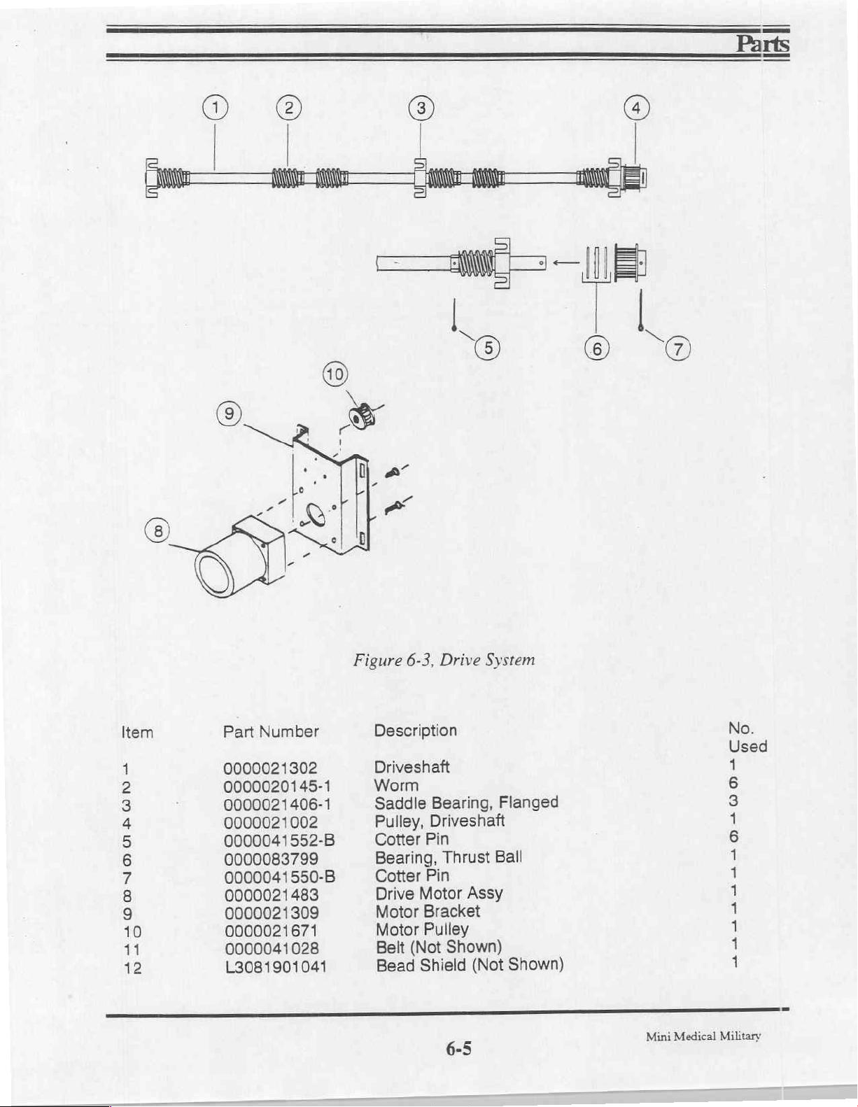
Item Part
1
2
3
4
5
6
7
8
9
10
11
12
Number
0000021302
0000020145-1
0000021406-1
0000021002
0000041552-B
0000083799
0000041550-B
0000021483
0000021309
0000021671
0000041028
L3081901041
Figure
6-3,
Description
Driveshaft
Worm
Saddle
Pulley,
Cotter
Pin
Bearing,
Cotter
Drive
Motor
Motor
Belt
Bead
Pin
Motor
Bracket
Pulley
(Not
Shield
Drive
Bearing,
System
Flanged
Driveshaft
Thrust
Ball
Assy
Shown)
Shown)
(Not
6-5
Mini
Medical
No.
Used
1
6
3
1
6
1
1
1
1
1
i
1
Military
Page 74
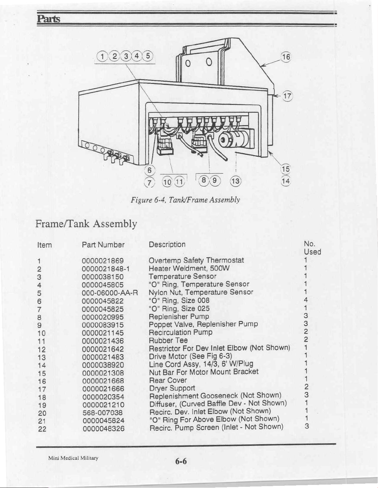
(a)
©
Frame/Tank
Item
1
2
3
4
5
6
4
8
9
10
11
12
13
14
15
16
v
18
19
20
21
22
Part
0000021869
0000021848-1
0000038150
0000045805
000-06000-AA-R
0000045822
0000045825
0000020995
0000083915
0000021145
0000021436
0000021642
0000021483
0000038920
0000021308
0000021668
0000021666
0000020354
0000021210
568-007038
0000045824
0000048326
Figure
Assembly
Number
6-4,
Tank/Frame
Description
Overtemp
Heater
Temperature
Ring,
"O"
Nylon
"O"
Ring,
"O"
Ring,
Replenisher
Poppet
Recirculation
Rubber
Restrictor
Drive
Line
Bar
Nut
Rear
Dryer
Replenishment
Diffuser,
Recirc.
Ring
"O"
Recirc.
Safety
Weldment,
Temperature
Nut,
Temperature
Size
Size
Valve,
Tee
For
Motor
Cord
Cover
Support
(See
Assy,
Motor
For
(Curved
Dev.
For
Pump
Sensor
Pump
Pump
Inlet
Above
Assembly
Thermostat
500W
Sensor
Sensor
008
025
Replenisher
Elbow
Inlet
Dev
6-3)
Fig
W/Plug
6'
14/3,
Mount
Gooseneck
Baffle
Elbow
Screen
Dev
(Not
Elbow
(Inlet
Pump
(Not
Bracket
Shown)
(Not
Not
-
Shown)
Shown)
(Not
Not
-
Shown)
Shown)
Shown)
No.
Used
AA
SN
ュー
ユニ
Mini
Medical
Military
6-6
Page 75
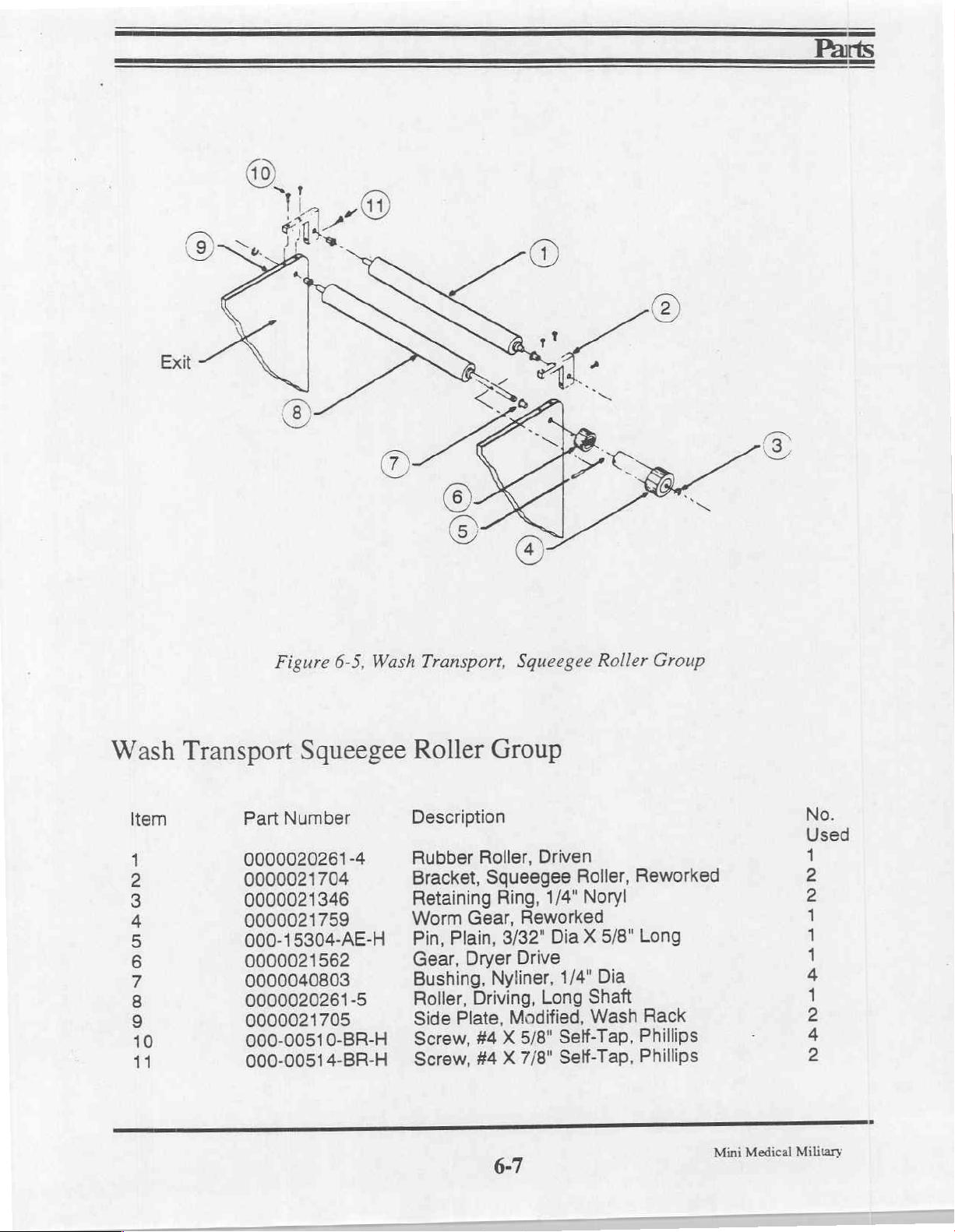
Exit
Wash
ぎ
WIN
O1
JO
©
(0
—
—
EX
Transport
3
Part
0000020261-4
0000021704
0000021
0000021759
000-15304-AE-H
0000021562
0000040803
0000020261-5
0000021705
000-00510-BR-H
000-00514-BR-H
Figure
6-5,
Squeegee
Number
346
Wash
Transport,
Roller
Description
Rubber
Bracket,
Retaining
Worm
Pin,
Gear,
Bushing,
Roller,
Side
Screw,
Screw,
Group
Roller,
Squeegee
Ring,
Gear,
Plain,
3/32"
Dryer
Nyliner,
Driving,
Plate,
X
#4
X
#4
Squeegee
Driven
Roller,
1/4"
Noryl
Reworked
Dia X 5/8"
Drive
1/4"
Long
Shaft
Modified,
5/8"
7/8"
Wash
Self-Tap,
Self-Tap,
Roller
Reworked
Long
Dia
Rack
Phillips
Phillips
Group
No.
Used
一
Nm
一
一
一
下
一
mA
Mini
Medical
Military
Page 76

Parts
Wet
Item
1
2
3
4
5
6
7
8
9
10
11
12
13
14
15
16
17
18
19
20
21
22
23
24
24
25
26
27
28
29
30
31
32
33
34
35
36
37
38
39
40
Transport
Assembly
Part
000-15304-AE-H
0000040803
000-00808-BQ-H
0000047802
0000021468
0000020474
0000020433
000-09500-AA-H
0000048205
0000020576
568-007004-1
0000021306-K
0000021467
0000021085
0000047701
000-09200-AF-H
000-00706-AM-H
0000020654
0000021346
0000048204
0000021796
0000021797
0000021238-1
0000021546
0000021546
0000021602
0000021603-1
0000021705
0000020652
000-05100-AA-H
0000020577
0000021493-2
000-00808-AM-H
000-0081
0000021616
000-00810-AM-H
0000021492-2
503-000746
503-000747
0000021658
0000020664
Number
6-BL-H
Description
Pin,
Plain,
Bushing,
Drive
Spring,
Driveshaft
Roller,
Bushing,
Washer,
Spacer,
Exit,
Dev
Gear,
Washer,
Worm
Gear,
Gear,
Ring,
Washer,
Screw,
Idler
Post
Ring,
Spacer,
Only)
Gear,
Gear,
Roller,
Group,
Film
Guide,
Film
Guide,
Diffuser
Side
Plate
Side
Plate
Shaft,
Nut,
Hex,
Guide,
Guide,
Screw,
Screw,
Rack
Screw,
Handle,
Lable,
Lable,
Key,
Key,
3/32" X 5/8"
Nyliner
Screw 8 X 1/2"
Extension
3/4"
Rubber
Grooved
Flat,
1/4"
and
Drive,
Retaining,
Gear
Drive,
Idler,
24P,
Retaining,
#6
6-32 X 3/8"
Retaining,
1/4"1.D. X .084
Idler,
54T
Idler,
60T
3/4"
Dia.
Wash
(Dev
(Dev & Fix)
(Wash
Film
Guide
8-32
Film
Film
8-32 X 1/2",
8-32 X 1",
Support,
8-32 X 5/8"
Extruded
Dev
Rack
Fix
Rack
Rack
Rack
Locater,
Locater,
Long
1/4"
1/4"
(Exit,
Wash
1.D. X 3/8"
Fix)
24P,
18T D Bore
24P,
24T
18T
5/16"
Split
Lock,
1/4"
Polyurethane
Rack
Entrance/Exit,
Entrance/Exit
Rack
Only)
Philips
Molded
Handle
Handle
O.D.
.640
Dia
Noryl
S.S.
Phil
Pan
Noryl
(Entrance,
Only)
(Fix)
Only)
Philips
Pan
Philips
2-Hole,
1-Hole,
(Dev & Wash)
Pan
Pan
Only)
(Entrance
Head
Wash
(Bottom
Head
Head
Head
Drive
Non
Drive
Side
&
Roller
Side
No.
Used
AN
00 00
00
©
—
o
D
D
020
0000060
08888
그
D
一
D
=
D
NN
2
=
oo
p
2
o
NB
D
1
nu
ュ
ュ
ユ
ユ
mmmmm
DD
DOD
Mini
Medical
Military
6-8
Page 77
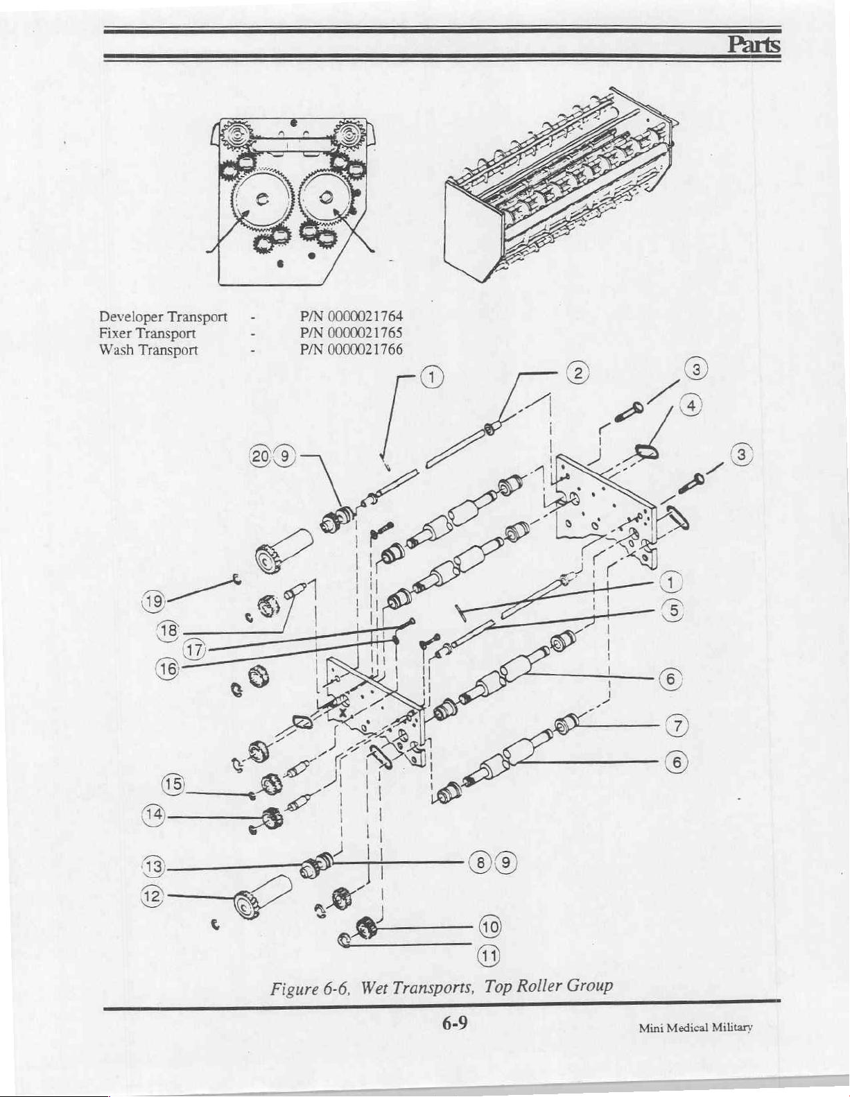
P/N
Developer
Fixer
Transport
Wash
Transport
Transport
0000021764
P/N
0000021765
P/N
0000021766
©
수
2
©
1
|
|
|
|
1
I
T
レン
o
a
る
NN
|
©)
κ
A
00
©
OS
BA
Figure
6-6,
ン
Transports,
Wet
6-9
Top
Roller
Group
Mini
Medical
Military
Page 78
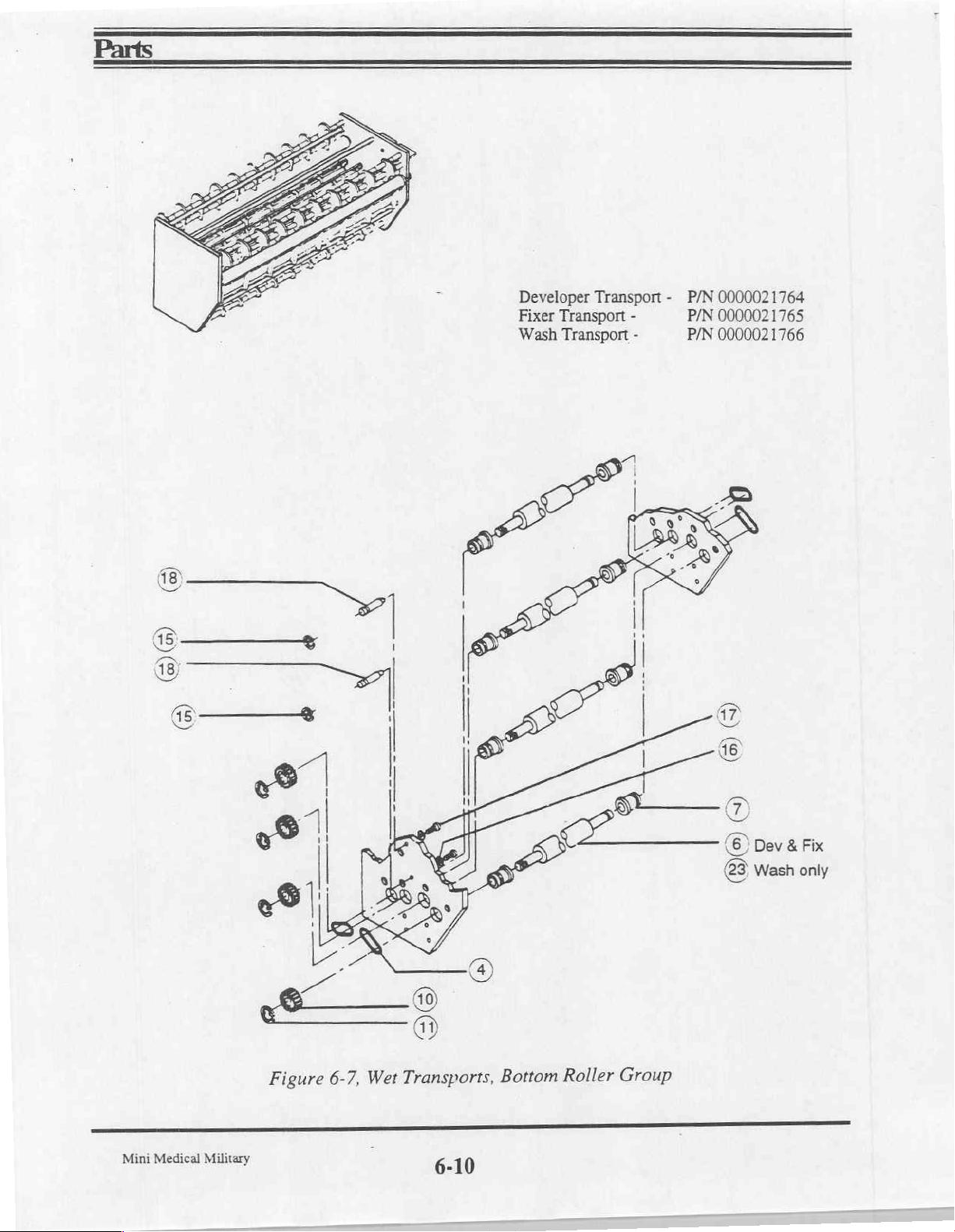
(5)
©
|
(©
|
Developer
Fixer
Transport
Wash
Transport
Transport - P/N
-
-
P/N
P/N
0000021764
0000021765
0000021766
Mini
Medical
Figure
Military
6-7,
Transports,
Wet
i
6-10
Bottom
Roller
Group
Page 79
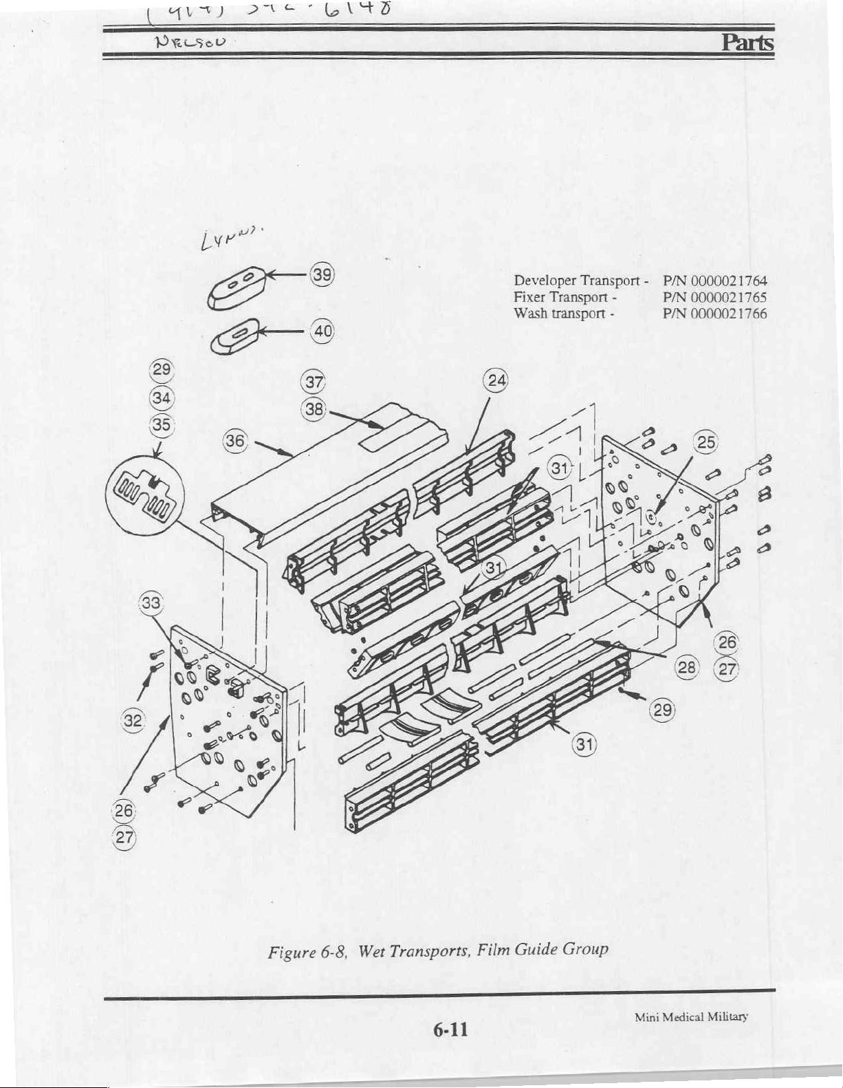
(RO
Prese
DD
Developer
Fixer
Transport
Wash
transport
Transport - P/N
-
-
P/N
P/N
0000021764
0000021765
0000021766
Figure
6-8,
Transports,
Wet
6-11
Film
Guide
Group
Mini
Medical
Military
Page 80
Dryer
Item
1
2
3
4
5
6
7
8
9
10
11
12
13
14
15
16
17
18
19
20
21
22
23
24
25
26
27
28
29
30
31
32
33
34
35
36
37
38
39
40
41
42
43
44
Assembly,
Part
Number
0000020572
0000047802
568-007095
0000021678
0000021
0000021175-1
0000021684
0000021726
0000021728
0000088981
0000081993
575-007028
0000037800
0000021781
0000021734
0000032676
0000021690
0000021675
0000037760
0000020260-2
000-01108-AW-R
0000021463
0000021579
0000020417-1
0000021564
086-000228
0000021563
0000021365
0000020575
0000020654
0000021086-3
0000021686
0000021730
0000021569
0000021582
0000021669
0000021231
0000021679
0000021
0000041550-B
0000021464
0000021467
000-00805-AQ-H
0000047701
Front
493-2
493-1
Exit,
P/N
Description
Bushing,
Spring,
Spacer,
Block,
Guide,
Lamp
Wire,
Reflector
Bracket,
Terminal
Strip
Marker,
Cover,
Thermostat,
Sensor,
Bracket,
Harness,
Air
Knife
Duct,
Jumper
Roller,
Screw,
Side
Plate
Pivot
Bearing,
Gear,
Ring
(Collar),
Gear,
Idler,
Gear,
Gear,
Stud,
Gear,
Air
Knife
Bracket,
Dryer
Coupler,
Vertical
Roller
Coupler
Guide,
Pin,
Cotter,
Plate,
Gear,
Screw,
Retaining,
Clip,
0000021767
Spring
Extension,
Film
Dryer
1-Piece
Assy,
Film
Assy
Air
Strip
Terminal
Dryer
Connector
Dryer
Assy,
Plenum
Rubber
Thumb
Stud,
Roller,
Driving
24P,
Idler,
Idler
24P,
Assy,
Blower
Assy
Fan
Rear
Duct
Assy
Duct,
1-Piece
|.R.
Mounting
Drive,
8-32 X 5/16",
Groove,
Guide
Adjustment
Film,
I.R.,
Guide
Knife
MS601-0
Strip
Dryer,
Rack
Rear
1/4-20 X 1/2"
Dryer
3/8"
Hub
24P,
24T
60T
24P,
48T
24T
Front
Mount
(2
Blower
Fan
Film,
1/16" X 1"
24P,
5/16"
Racks
Dryer
14",
High
Tap,
Per
Dryer
24T
3/8"
275W,
Limit
8/32"
Machine,
Soc.
Set
Noryl
115V
1
Per
Dryer)
No.
Used
=
№
人
N
Mini
Medical
Military
6-12
Page 81
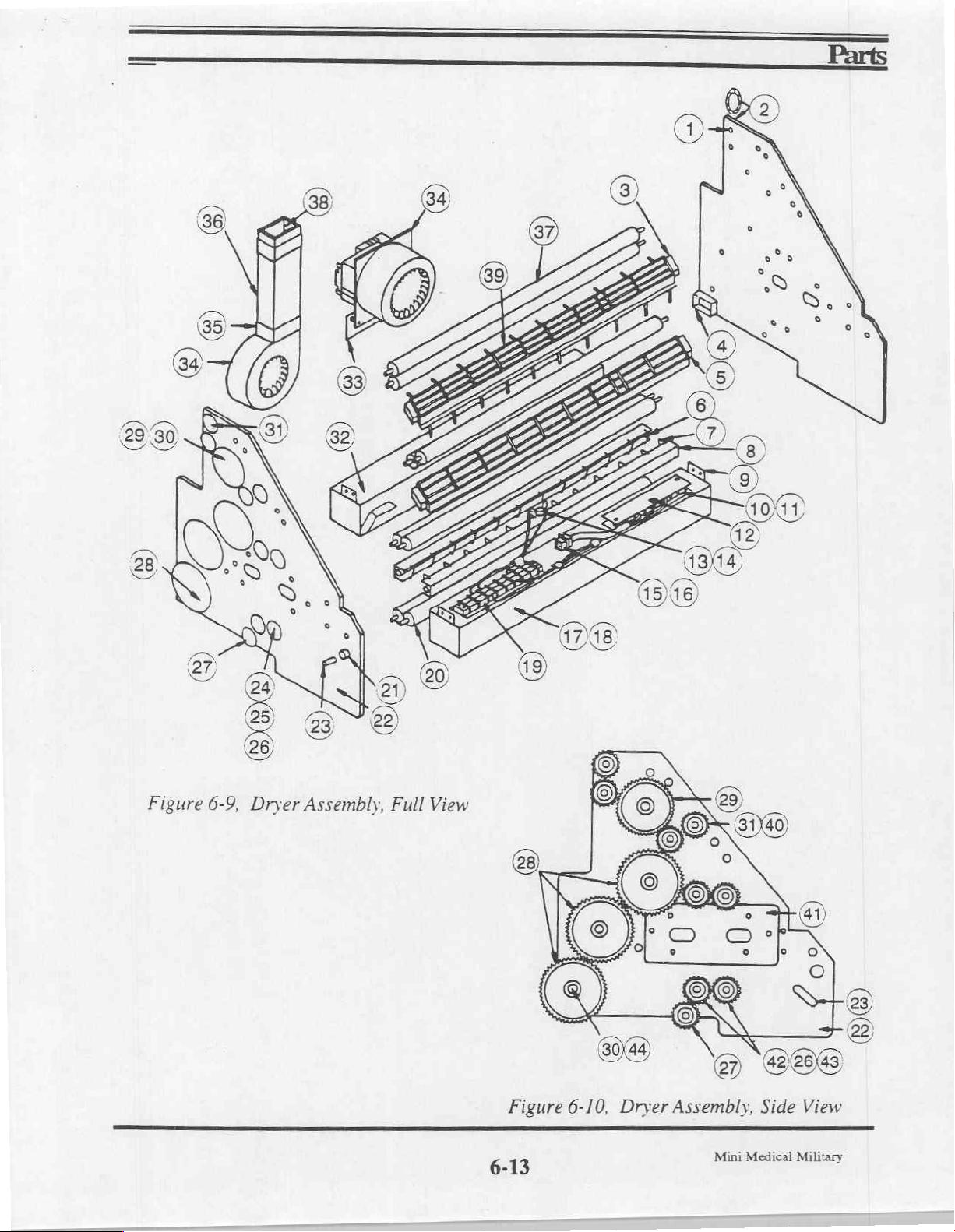
OO
S
v
Si
©
Q
o
>
k,
o
x
<
a
a
8
=
5
u
=
>
È
=
Figure
6-10,
Dryer
Assembly,
Side
View
6-13
Mini
Medical
Military
Page 82

Not
available
assembly,
order
P/N
separately.
P/N
0000021145.
0000021525).
Order
(For
complete
220VAC,
Recirculation
Item
WP
ONOuB
Pump
Part
0000045830
0000091099
0000091100
0000091101
0000091102
0000045826
0000091923
Number
Figure
P/N
6-11,
Recirculation
0000021145
-Description
"O"
Ring,
Housing,
Shaft,
Washer,
Impellor
"O"
Ring,
Cover
March
1/2
Impellor
Rear
Magnet
Size
Adapter
Pump
027
Pump
EP
70,
No.
Used
Duro
Mini
Medical
Military
6-14
Page 83

Plumbing
Schematic,
Item Part
1
2
3
4
5
6
7
8
9
10
11
12
13
14
15
16
17
18
19
20
21
22
0000035316
0000021483
0000021145
0000020995
0000021436
0000021904
0000021569
0000021903
0000041405
0000046251-C
800-070391
0000021880
0000021848-1
0000021869
0000021851
0000049004
0000046251-C
0000046191-E
0000046303-C
0000021051
0000021700
0000041449
Number
(Figure
Description
P.C.B
Main
Drive
Recirulation
Replenisher
Tee
Fitting,
Clamp,
Fan
Assy,
Nipple,
Clamp,
Elbow,
Clamp,
Jacket,
Heater,
Sensor
Bracket,
Valve,
Elbow,
Nipple,
Spring,
Hanger,
Drain
Clamp,
6-12)
Assy,
Drain,
Panel
Main
Motor
Pump
Pump
Rubber
SNP
22
Lower
Heat
Exchanger
Hose,
1/2"
SNP
Heat
500W,
Assy,
Worm
Barb
28
Exchanger
110V
Overtemp
Heater
Mounting
Specialty
90Deg,
1/4
1/4
MPT
Replenisher
Replenisher
12
SNP
Harness
Gear
1/2"
X
FN
FPT
PVC
3"
X
Pump
Pump
Barb
Safety
(Not
FPT
1/4
X
Mount
Shown)
No.
Used
1
1
2
3
2
2
1
2
12
3
2
1
1
1
1
3
3
3
12
6
1
9
Mini
Medical
Military
6-15
Page 84

SB
à
=
O
Fsg
a
в
(oa)
45)
we
bo
の
=
O
a
Bo} oa}
©
T,
\
DÁ
= =
Ree) Grp)
©
ZA
SSL
E
Bel
Fa
O
DA
©
m
=
(2)
E
ló
2
8)
O
©
DD)
Figure
Mini
Medical
Military
6-12,
Plumbing
Schematic
Page 85

Notes:
Mini
Medical
Military
6-17
Page 86
WARNING:
any
electrical
adjustment
a
qualified
technician
technician.
Never
attempt
troubleshooting,
or
service
electrician,
or
factory trained
unless
electronics
to
perform
you
service
are
 Loading...