

Page 1
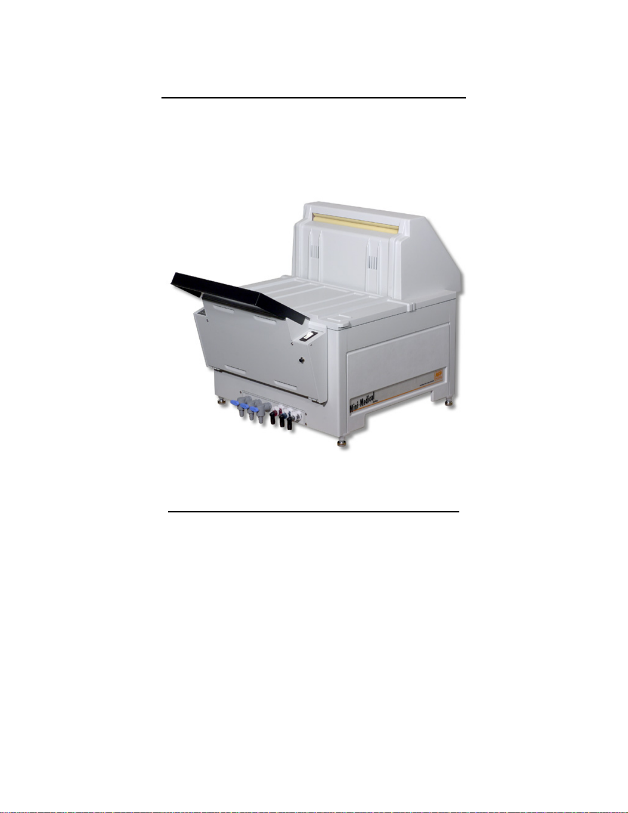
Mini-Medical Series
Troubleshooting Reference
Trained Service Personal ONLY
Observe ALL safety Procedures in the service manual
Reference: Installation, Operation, Service & parts Manual (P/N:0000061122)
Page 2

Table of Contents
1. No Dryer Heat -Wet Film (Fan not working)_______________ 1
2. No Dryer Heat -Wet Film (heaters not working)____________ 2
3. No Developer Heat (Light Film)_________________________3
4. Over Heated Developer (Dark Film)______________________4
5. Machine Doesn’t Go Into Standby Mode__________________5
6. Low Developer Light is Always On_______________________6
7. Developer Heating Time is Too Long_____________________7
8. Replenishment Pump is not Working_____________________8
9. Fixer/Developer is Disappearing From the Machine_________9
10. The Machine Doesn’t Come On-No LED on Logic Board_____10
11. The Main Breaker Trips When the Machine is Turned On_____11
12. Only One Replenishment Pump is Working All the Time______11
13. Resistances reference for 115V Processors ________________12
14. Resistances reference and parts numbers for 230V Processors_13
Note: If you have a 230V Processor, please consult page 11 for common
resistances values and parts numbers.
Key
> Greater Than
< Lower Than
= Equal To
≈ About the Same
Page 3
1)
plug
p
g
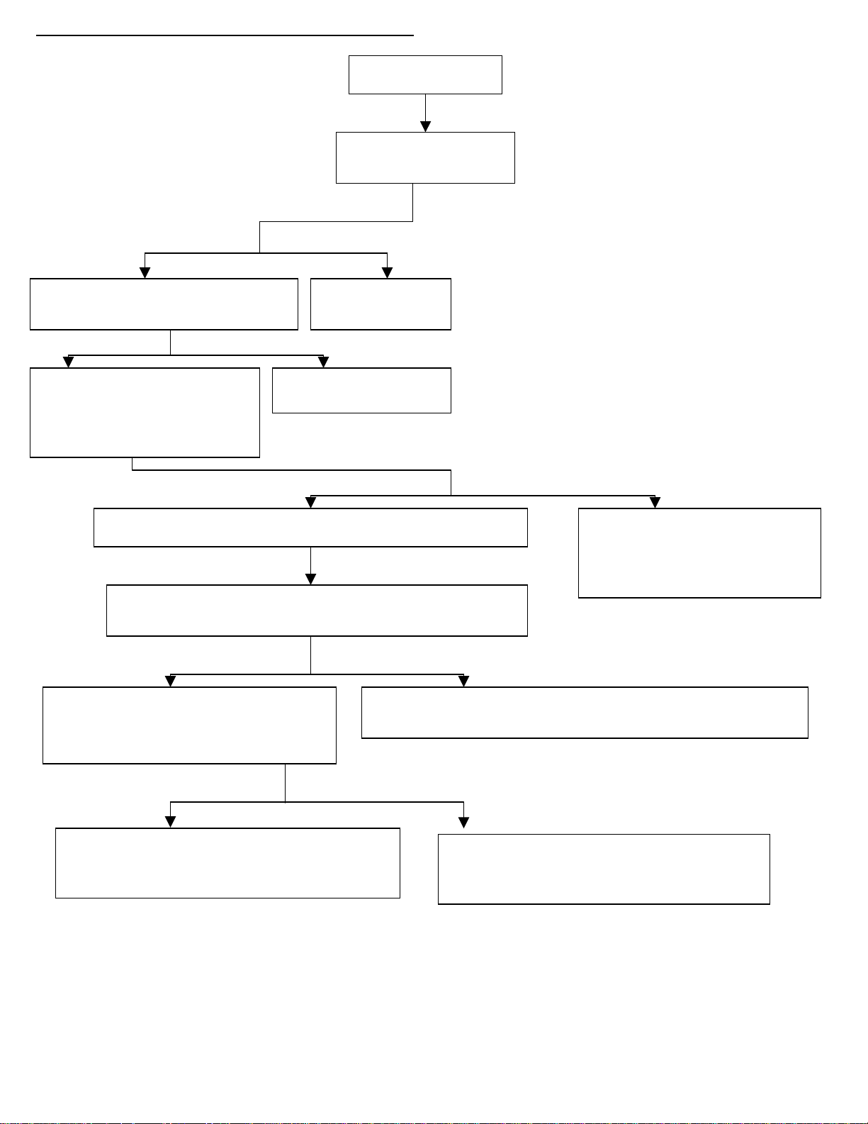
No Dry Heat -Wet Film (Upper Fan is not Working)
Wet Film
Check Fuse F7 on the
A/C Board
Fuse Good Fuse bad
Check Voltage between TB1-1 (Logic
Board) and J1-4 (A/C Board)
Replace Fuse F7
P/N:
0000032013
Voltage No Voltage
Check the voltage between the
two external slots of the J11 Plug
located on the right side of the
machine.
Replace A/C Board
P/N: 9992305008
Voltage No Voltage
Check the dryer rack wiring on the back of the machine
Unplug the 6-P connector and check the voltage between
the orange and the thick white wires inside the plug.
There is a broken wire between
the J11 plug and the A/C Board.
Replace the PC board above the
. P/N: 0000035316
Voltage No Voltage
Plug the connector back & check
Voltage between 2 and 4 (white &
orange wires on the right strip)
Replace the harness (between the J11 plug and the dryer rack
lug. P/N: 0000032677 (Harness for the Dryer Rack)
Voltage No Voltage
Replace the upper fan.
P/N: 0000021569 (115V)
P/N: 0000021637 (230V- S/N 8677 & hi
her)
Replace the harness (between the plug and
the strip on the dryer).
P/N: 0000032676
Note: If the dryer is working check / fix replenishment rates:
Weak fixer doesn’t harden well and therefore, the film will not dry adequately.
1
Page 4
2)
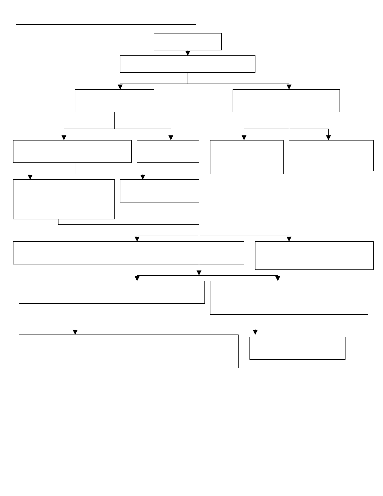
No Dry Heat -Wet Film (Dryer Lamps are not Working)
Wet Film
Check Light L1 on the Logic Board
Light On Light Off
Check Fuse F5 on the
A/C Board
Disconnect J5 from the Logic
Board (Temp’ Sensor).
Fuse Good Fuse bad Light is On Light is Off
Check Voltage between TB1-1 (Logic
Board) and J1-1 (A/C Board)
Replace Fuse F5
P/N: 0000032013
Voltage No Voltage
Replace
Temperature Sensor
P/N: 0000021781
Replace Logic Board
P/N: 9992305017 (115V)
P/N: 0000035304 (230V)
Check the voltage between the
two external slots of the J10 Plug
located on the right side of the
machine.
Replace A/C Board
P/N: 9992305008
Voltage No Voltage
Check the dryer rack wiring on the back of the machine. Unplug the 6-P connector and
check the voltage between the thick white wire and brown wire inside the plug.
There is a broken wire between the J11
plug and the A/C Board. Replace the PC
board above the plug. P/N: 0000035316
Voltage No Voltage
Check the voltage between 2 (Right to left-white wire on
the right) and 2 (Left to right-brown wire on the left).
Replace the harness (between the J11 plug and
the dryer rack plug. P/N: 0000032677 (Harness
for the Dryer Rack)
Voltage No Voltage
If the heaters are not working at this point, replace them.
P/N: 0000021175-1 (115V)
P/N: 0000021775-2 (230V)
Replace Over Temp’ Safety
P/N: 0000037800
Note: If the dryer is working check / fix replenishment rates:
Weak fixer doesn’t harden well and therefore, the film will not dry adequately.
2
Page 5
3)
p
p
p
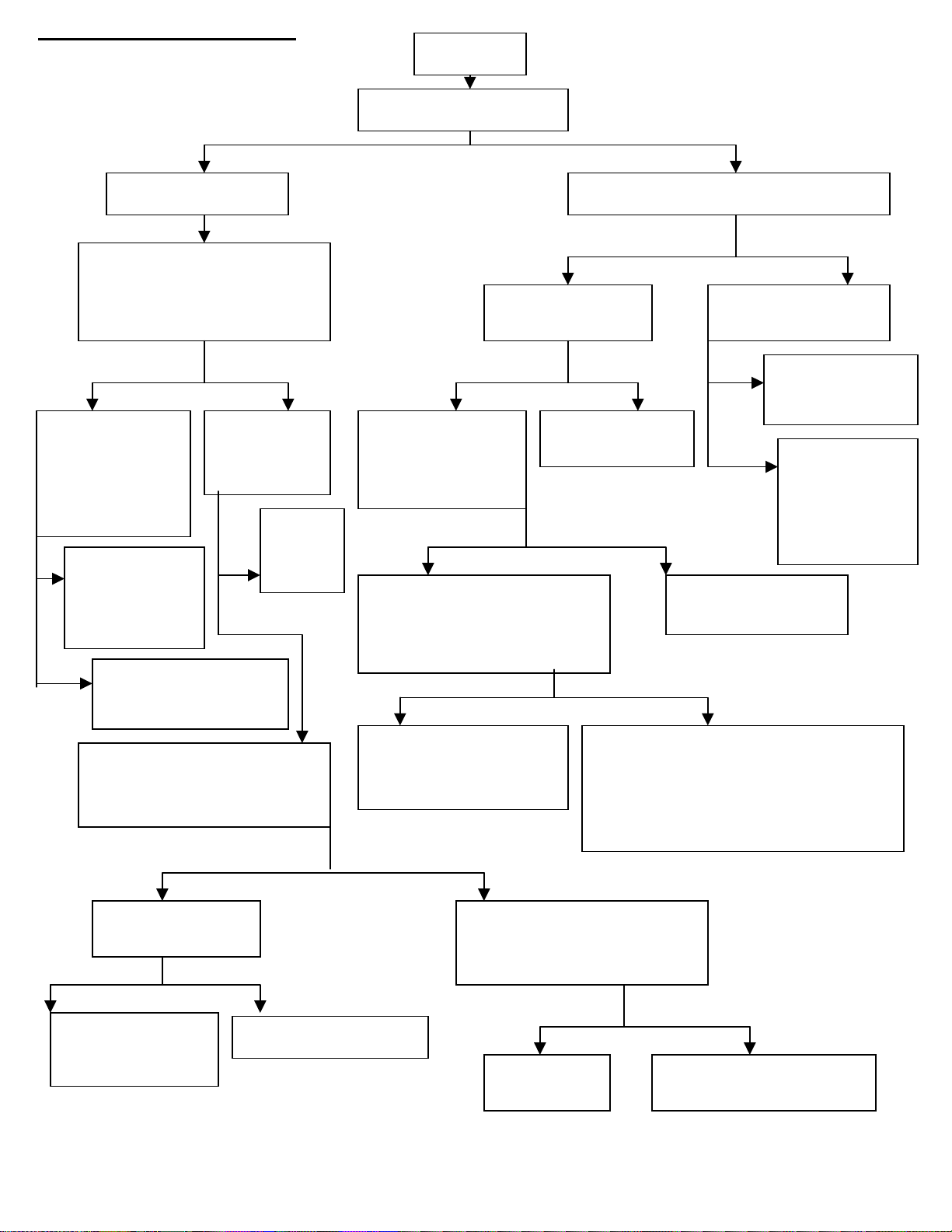
No Developer Heat (Light Film)
Light Film
Check DEV Temp Light
Light No Light
Fill Developer Tank
Check light, L2, on the Logic board
Light No Light
Check the voltage between
the two external slots of the J4
lug located on the right side
of the machine (115V)
Check Fuse F4 on
the A/C Board
Disconnect J4 on the
Logic Board
Voltage No Voltage Fuse Good Fuse bad Light
Check the
N
resistance of the
heat exchanger
Should be:
23Ω±10%
Voltage No Voltage
Bad Bad
Good
Replace Heat
Exchanger
P/N: 0000021848-1
(115V)
P/N: 0000021848-2
Good
Voltage No Voltage
Rotate R-20 clockwise on
logic board until the DEV
Temp is blinking steadily.
Exchange I/C’s U1 & U2 on
the A/C board and see if the
roblem was solved
Check if fuse
F4 on the
A/C Board
Replace
Fuse F4
P/N:
000003201
Check Voltage
between TB1-1
(Logic Board) &
J1-2 (A/C Board)
Check the voltage between
the two external slots of the J4
lug located on the right side
of the machine.
Replace the Heat Exchanger:
P/N: 0000021848-1 (115V)
P/N: 0000021848-2 (230V)
Replace Fuse F4
P/N: 0000032011
Check if there is a broken wire between
the J4 plug and the A/C Board or
whether the connections on the PC
board behind the J4 plug are loose.
P/N:
0000035316 (PC Board + Harness)
No Light
Replace A/C Board
P/N: 9992305008
Replace Temp’
Sensor
P/N: 0000038157
Replace Logic
Board
P/N: 9992305017
(115V)
P/N: 0000035304
(230V)
DEV Temp is On DEV Temp is Off
Check if Dryer
lamps are working
Not Working Working
Check voltage between J1-2
on the A/C Board and TB1-1
on the Logic Board
Voltage No Voltage
Replace the A/C
board
P/N: 9992305008
Machine should work.
Machine
should work
There is a broken wire
between the two boards
Note: check / fix developer replenishment rates: Weak developer chemistry will not develop well.
3
Page 6

Dark Films-Over Heated Developer
p
p
p
4)
Light is On Light is Off
Light Stays On Light turns Off
Voltage No Voltage
Add Developer so it covers the low level sensor and calibrate the temperature by rotating trim
ot R-20 on the Logic Board counterclockwise to reduce the temperature. Let the machine
work for few minutes and test the temperature of the developer. Continuously check the light
L2 on the Logic Board while testing the temperature of the developer. Once the temperature
stabilizes at the required temperature the light L2 should go out.
If the develo
Replace the Logic Board
P/N: 09992305017
Note: Be sure the darkroom does not have light leaks that will pre-expose the film.
er temperature overshoots the specified temperature - see below:
Check Light L2 on the Logic Board
If the light is on the sensor calls the
heater to supply more heat. If the
developer is already over heated, the
roblem might be with the sensor or
with the Logic Board.
Disconnect J4 from the Logic Board
and short and the two pins. That
bypasses the sensor.
Dark Films
Replace the AC Board
P/N: 9992305008
The machine is good.
Keep the pins shorted and check the voltage between TB1-1
(white wire on logic board) and J1-2 (red wire on AC board).
Replace the Sensor
P/N: 0000038157
4
Page 7

5)
Pumps Work Continuously-Machine doesn’t go into Standby mode
Machine fails to go into Standby Position- Calibrate the distance from magnets to pendulums
according to the description at the bottom of the page. If it didn’t solve the problem, see below.
Symptoms
Weak Magnets, Fixed
Pendulum in upper position
Switch Stuck in
Closed Position
Switch is adjusted too far
from the magnets
Unplug J13 from the Logic Board and wait
8-10 seconds for the pumps to shut down
Pumps do shut off Pumps don’t shut off
Problem is in the ready tone generator
board: Either the switch or the magnet.
Unplug connector J12 from the logic board and
wait 8-10 seconds for the pumps to shut down
Pumps do shut off Pumps don’t shut off
Unplug the right switch, J13, from the
ready tone generator board and short the
middle and right pins. Wait 8-10 seconds
for the pumps to shut down.
Replace the Logic Board
P/N: 9992305017 (115V)
P/N: 0000035304 (230V)
Replace the manual
replenishment switch
P/N: 0000037112
Pumps do shut off Pumps don’t shut off
Replace the right switch and the right pendulum.
P/N: 0000021878 (Switch)
P/N: 0000021893 (Pendulum)
Return J13 to place and repeat the
same procedure for the left switch,
J14 (short middle and right pins).
Pumps do shut off Pumps don’t shut off
Replace the left switch and the left pendulum.
P/N: 0000021878 (Switch)
P/N: 0000021893 (Pendulum)
Short J13 and J14
Simultaneously.
Pumps do shut off Pumps don’t shut off
Replace left and right switches and pendulums.
P/N: 0000021878 (Switch)
P/N: 0000021893 (Pendulum)
Replace the Ready Tone Generator Board.
P/N: 0000035306-1
If after replacement the problem still exists, you will have to calibrate the distance of the magnets from the pendulums.
The right distance can be determined by measuring the voltage between ground chassis (left bottom screw on the logic
board and the green middle wire on the sensor plug. The voltage should be zero when no film is in the feed tray and 11V
when a film is present (then the pendulums are lifted by the thickness of the film).
5
Page 8

6)
Low Developer Level Light is always ON
Low Developer Level Light is On
Fill developer tank up to sensor level
Light Still On No Light-Problem Solved
Clean the level sensor (Screw)
inside the developer tank
Machine should work
Light Still On No Light-Problem Solved
Check the wires between the level
sensor and the Logic Board, J8:
Unplug J8 and short the pins.
Machine should work
Light Still On No Light-Problem Solved
Replace Logic Board.
P/N: 9992305017 (115V)
P/N: 0000035304 (230V)
Make sure that the heat exchanger
ground wire (green wire) is in place.
If problem hasn’t been solved replace the sensor harness
P/N: 0000032578
5A)
Q)
During installation and initial set-up, the LOW DEV and DEV TEMP lights are ON even when the developer tank is
full with water.
A)
As water cannot conduct well enough, the level sensor will signal a low solution level to the PC board and
automatically disable the developer heater. Make sure to add kosher/coarse salt or some developer chemical to the
water to allow conductivity.
6
Page 9

7)
p
p
Developer Heating Time is too Long
Background:
The re-circulation pump circulates the developer through the heat exchanger and into the developer tank.
A thermostat measures the developer temperature at the exit from the heat exchanger. When the temperature
exceeds 165 F the thermostat will divert the current from the heat exchanger and by that will prevent further
heating. It will allow heating only when the temperature of the developer drops back to the reset point. When the
developer re-circulation pump is not working properly the amount of developer going through the heat exchanger
is small and therefore, heated fairly quickly. Since the th ermostat senses only the temperature of the fluid in its
roximity, which reaches 165 F quickly when the volume of fluid is small, it opens up and prevents additional
heating. As a result, the developer heating time is extended significantly.
Check if the re-circulation pump is working by
hysically listening to it or touching it, or by
observing the developer flow coming into the
developer tank. The inlets are located under the
white plastic diffuser and on the left wall of the
developer tank.
If the re-circulation pump is not working appropriately and
the developer flow is too weak than the pump has to be
replaced.
P/N: 0000022100 (115V-Newer model, blue/green pump)
P/N: 0000022101 (230V- Newer model, blue/green pump)
P/N: 0000021145 (115V-Older model, red/brown pump)
P/N: 0000021101 (230V- Older model, red/brown pump)
7
Page 10

8) The Replenishment Pump/s are not Working (Developer and/or Fixer Pumps).
(
p
p
Remove the right panel of the machine.
-If developer replenishment pump is not working:
Check the voltage between the two external slots of plug J3.
-If fixer replenishment pump is not working:
Check the voltage between the two external slots of plug J6.
Voltage No Voltage
Good Bad
LED ON NO LED
Shut down the machine and
unplug the pump’s plug.
Check resistance between the two
external
Good Resistance Bad Resistance
Make sure that the
end caps of the
umps are not
calcified and that
the hoses are clean
and free of
chemical build up.
ins: 134 Ω ± 10 %
Replace pump:
P/N: 0000020995
(115V)
P/N: 0000020995-1
230V)
Check if fuse F-1 on logic board is good
See if LEDs L5 and L6
are flashing when you
activate the pumps.
Replace fuse F1
P/N: 0000032003
Replace the logic board
P/N: 9992305017
Check for voltage between the logic board and the AC board:
For developer replenishment pump:
Check between TB1-1 & J1-7 (pink wire on AC board)
For fixer replenishment pump:
Check between TB1-1 & J1-6 (blue wire on AC board)
Voltage No Voltage
Replace the PC board located above
the plug.
P/N: 0000035316.
(Most probably the soldering of the
wire coming from the AC board to
the board above the plug was broken.
You can verify it by removing the PC
board and checking the connections).
Replace the AC Board
P/N: 9992305008
8
Page 11

9) Fixer/Developer is Disappearing from the Machine
Chemical can be disappearing from the machine in three different ways:
a) Evaporating.
b) Siphoning.
c) Leaking.
a)
If the temperature of the developer is about 95°F and therefore, the temperature
of the fixer cannot be more than that, the chemical could not be evaporating.
b)
Siphoning can happen when the white gooseneck tube outlet is inside the
chemical: the chemical will flow back to the reservoir tanks outside the machine.
To prevent it, reposition the gooseneck slightly above the chemical level. Don’t
raise it to much in order to prevent splashing of chemical during replenishment.
c)
Check the drainage ball valve located at the front of the processor. If this valve
is leaking the chemical will go directly to the drainage without anybody noticing
it.
P/N: 0000087222 (Gray W/Blue Handle)
P/N: 0000087220 (Black-older style)
If you will increase the replenishment rate to compensate the disappearance of
the chemical the problem will not be solved. The outcome will be a greater rate
of disappearance, as you will use more chemistry per sheet.
And by comparing it to the other chemical (that does not disappear and has a
regular replenishment rate) it will seem as if the disappearance rate is greater.
9
Page 12

10. The Machine Doesn’t Come On: No LED on the Logic Board.
j
p
p
g
Check for line voltage (115V) at the On/Off Switch when the machine is turned On.
See if lower fan, solenoid or motor works
Voltage / components work No Voltage / components don’t work
Check voltage on the Logic board between
the white and black wires located on TB1-1 and
TB1-5, respectively.
Voltage No Voltage
Disconnect connector J14 from the logic board and
ump the two pins. That will bypass the cover switch.
LED On LED still off
LED On LED still off
Replace Cover Switch.
P/N: 0000037051
Make sure that the following connectors are not connected
in reverse and that they are sitting correctly on the pins:
a) J7 on the logic board
b) J2 on the AC board
c) 8 Pin connector underneath the LED board
Make sure that all other connectors are also in
Problem resolvedmachine should work
Check the On/Off switch and voltage
source from the socket. Replace switch
if required. P/N: 0000037283
Make sure that the wires are secured in place.
If one of the connectors on the logic board, AC
board or LED board (underneath the left upper
anel) is not connected properly it will shut down
all LEDs on the lo
Replace the Logic board
P/N: 9992305017
ic board.
lace.
Page 13

11. The Main Breaker turns off When the Machine is turned On.
p
12.
One Replenishment Pump is Working Continuously
LED OFF LED ON
Replace the A/C Board.
P/N: 9992305008
Turn off the unit and remove the right panel from the processor.
Disconnect all plugs from the unit and then turn it back on.
If only one replenishment pump is working all the time check if
the corresponding LED on the logic board in On or Off:
LED L5-Developer Replenishment.
LED L6-Fixer Re
lenishment
If both LEDs are flashing all the time we have two problems:
1. The pumps should be flashing only for 8-10 seconds
when a film is inserted.
2. One pump is not working.
To resolve the first problem you should consult with
troubleshooting chart number 5.
To resolve the second problem you should consult with
troubleshooting chart number 8.
Page 14

AFP Imaging
250 Clearbrook Road
Elmsford, NY 10523
Tel: 1.914.592.6100
Fax: 1.914.592.6148
www.afpimaging.com
Mini Medical Resistance
120 Volt
Description Part Number Resistance Value
Recirculation Pump
March (red) (Old Style)
Recirculation Pump
Iwaki (blue/green)
(New Style)
Developer Heater 0000021848-1
Replenish Pump 0000020995
Water Solenoid 0000049008
Dryer Lamps (Heaters) 0000021175-1
Dryer Fan 0000021569
Drive Motor 9992305311
9992305035 (21145)
0000022100
10
31.8 Ω ± 10%
116 Ω ± 10%
23 Ω ± 10%
134 Ω ± 10%
430 Ω ± 10%
43 Ω ± 10%
26 Ω ± 10%
104.5 Ω ± 10%
Page 15

Mini Medical Resistance
230 Volt
Description
230 Volt
Recirculation Pump
March (red) (Old Style)
Recirculation Pump
Iwaki (blue/green)
Developer Heater 0000021848-2
Replenish Pump 0000020995-1
Water Solenoid 0000049013
Dryer Lamps (Heaters) 0000021175-2
Dryer Fan 0000021637
Drive Motor
230 50/60Hz
0000021525
00000022101
0000021490
Part Number Resistance Value ± 5%
Parts List for 230V
PC Logic Board
Drive Motor
Heater Assembly
0000021848-2
1 KΩ%
470 Ω
90 Ω
560 Ω
2.5 KΩ
170 Ω ea.
100 Ω
410 Ω
0000035304
0000021507
Replenishment Pump
0000020995-1
Heating Lamps I.R 0000021175-2
Recirculation Pump
0000021101
(old style-red/brown)
Recirculation Pump
0000022101
(new style-blue/green)
Fan Assy, Lower 0000021637
Heater, 550W 0000021848-2
11
 Loading...