


HCB021801
7.3AR
Read the BIKE GUIDE before using this OWNER’S MANUAL.
Lire le GUIDE D’UTILISATION DU VÉLO D’EXERCICE avant de se servir du présent MANUEL DU PROPRIÉTAIRE.
Lea la GUÍA DEL USUARIO DE LA BICICLETA ESTACIONARIA antes de usar este MANUAL DEL PROPIETARIO.
EXERCISE BIKE OWNER’S MANUAL
MANUEL DU PROPRIÉTAIRE DU VÉLO D’EXERCICE
MANUAL DEL PROPIETARIO DE LA BICICLETA ESTACIONARIA
7.3AU
AFG14_7.3AR_AU_OM_r1_5.indd 1 5/12/14 11:12 AM

2
2 ENGLISH
32 FRANÇAIS
62 ESPAÑOL
AFG14_7.3AR_AU_OM_r1_5.indd 2 5/12/14 11:12 AM

3
IMPORTANT PRECAUTIONS
SAVE THESE INSTRUCTIONS
When using an exercise product, basic precautions should always be followed, including the following: Read all instructions
before using this exercise bike. It is the responsibility of the owner to ensure that all users of this exercise bike are adequately
informed of all warnings and precautions. If you have any questions after reading this owner’s manual, contact Customer
Tech Support at the number listed on the back panel.
AFG14_7.3AR_AU_OM_r1_5.indd 3 5/12/14 11:12 AM
4
READ AND SAVE ALL INSTRUCTIONS BEFORE ASSEMBLING OR USING THIS
EXERCISE BIKE. IT IS STRONGLY RECOMMENDED TO TAKE THE FOLLOWING SAFETY
INSTRUCTIONS.
CAUTION: If you experience chest pains, nausea, dizziness or shortness of breath, stop exercising immediately and consult
your physician before continuing.
Use this exercise bike for its intended purpose as described in this manual. Do not use attachments that have not been
recommended by the manufacturer.
Never operate the exercise bike if it is not working properly, or if it has been damaged. Contact Customer Tech Support or
the authorized dealers for examination and repair.
Do not use the exercise bike without proper footwear. NEVER operate the exercise bike with bare feet.
Do not wear any clothing that might catch on any moving parts of this exercise bike.
Keep hands and feet clear at all times from moving parts to avoid injury. Never turn the pedal cranks by hand.
Do not dismount the exercise bike until the pedals are at a complete STOP.
Do not attempt to ride the exercise bike in a standing position at high RPMs until you have practiced at slower speeds.
Do not insert any object, hands or feet into any openings, or expose hands, arms or feet to the drive mechanism or other
potentially moving part of the exercise bike.
Do not use any equipment that is damaged or has worn or broken parts. Use only replacement parts supplied by Customer
Tech Support or the authorized dealers.
Do not operate where aerosol (spray) products are being used or when oxygen is being administered.
Close supervision is necessary when used near children, invalids or disabled people.
When the exercise bike is in use, young children and pets should be kept at least 3 meters / 10 feet away.
Ensure that adjustment levers (seat and handlebar fore-and-aft) are properly secured and do not interfere with range of
motion during exercise.
This product contains chemicals known to the State of California to cause cancer and birth defects or other reproductive
harm.
WARNING
AFG14_7.3AR_AU_OM_r1_5.indd 4 5/12/14 11:12 AM
5
ASSEMBLY
There are several areas during the assembly process that special attention must be paid. It is very important to follow the
assembly instructions correctly and to make sure all parts are firmly tightened. If the assembly instructions are not followed
correctly, the exercise bike could have parts that are not tightened and will seem loose and may cause irritating noises. To
prevent damage to the exercise bike, the assembly instructions must be reviewed and corrective actions should be taken.
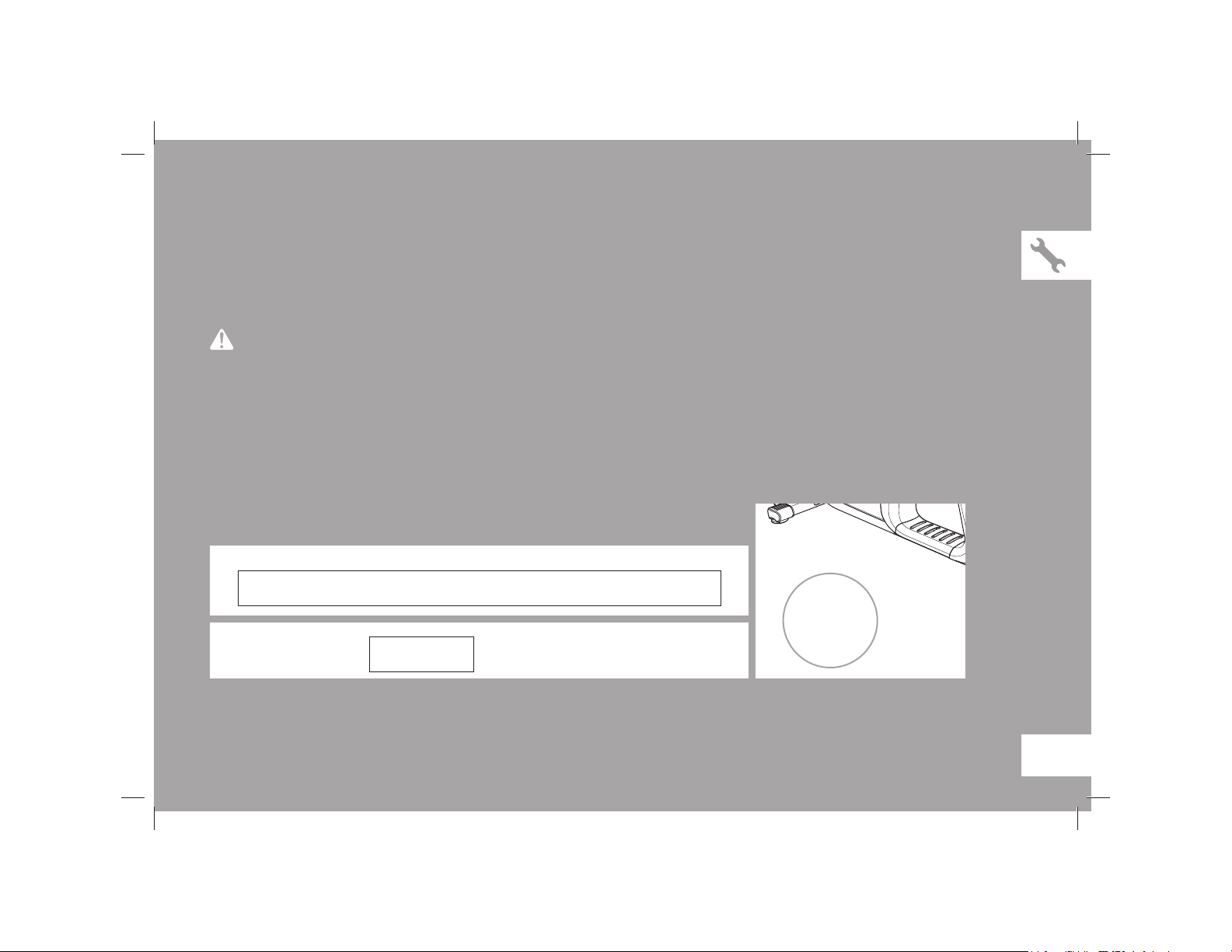
Before proceeding, find your exercise bike’s serial number and enter it in the space
provided below. The serial number will be located on a white sticker with a bar code.
ENTER YOUR SERIAL NUMBER AND MODEL NAME IN THE BOX BELOW:
» Refer to the SERIAL NUMBER and MODEL NAME when calling for service.
» Be sure to enter both the SERIAL NUMBER and MODEL NAME on your warranty card.
MODEL NAME: AFG EXERCISE BIKE
WARNING
SERIAL NUMBER:
SERIAL NUMBER LOCATION
AFG14_7.3AR_AU_OM_r1_5.indd 5 5/12/14 11:12 AM
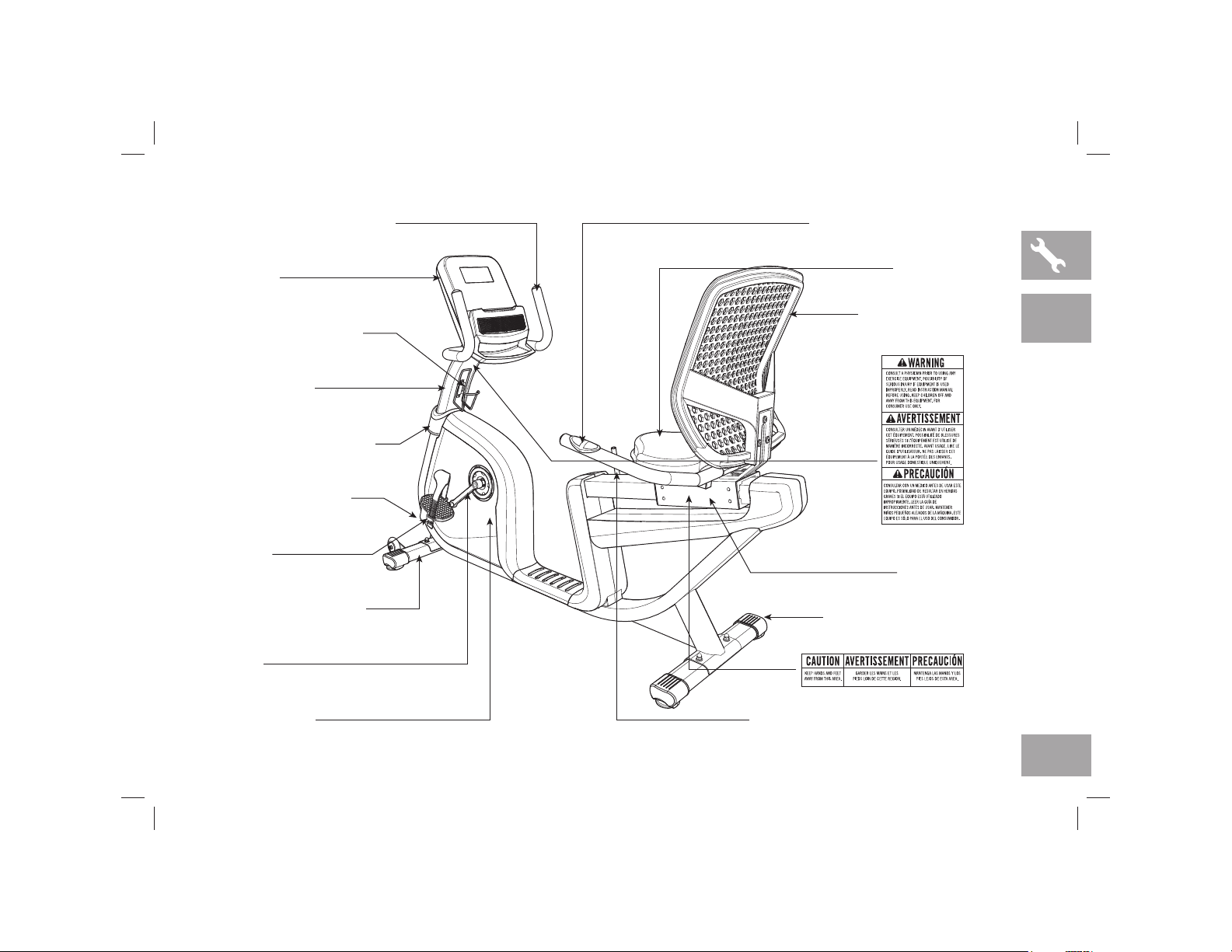
6
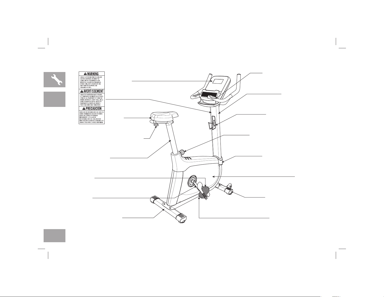
CR AN K
WATER BO TT LE H OL DE R
PUL SE GR IP HA NDL EB ARS
RE AR STAB IL IZ ER TUB E POW ER CO RD SOC KE T
CON SO LE
SE AT PO SI TI ON A DJ US TM ENT KN OB
SE AT PO ST TUB E
SE AT HE IG HT AD JUS TM ENT KN OB
FRO NT S TAB ILI ZE R T UB E
SE AT
PED ALS
SHR OU D
CON SO LE M AS T
CON SO LE M AS T G ROM ME T
7.3AU
AFG14_7.3AR_AU_OM_r1_5.indd 6 5/12/14 11:12 AM
7
7.3AR
CR AN K
WATER BO TT LE H OL DE R
PUL SE GR IP HA NDL EB ARS
RE AR STAB IL IZ ER TU BE
CON SO LE M AS T H AN DLE BA RS
POW ER CO RD SOC KE T
CON SO LE
SE AT SL ID E
SE AT PO SI TI ON A DJ US TM ENT LE VE R
FRO NT S TAB ILI ZE R T UB E
MES H S EAT BACK
SE AT BA SE
PED ALS
FRO NT S HR OU D
CON SO LE M AS T
CON SO LE M AS T G ROM ME T
AFG14_7.3AR_AU_OM_r1_5.indd 7 5/12/14 11:12 AM
8
TOOLS INCLUDED:
F 13/15mm Flat Wrench
F Phillips Screwdriver/Allen Wrench
PARTS INCLUDED:
F 1 Bike Frame
F 1 Console
F 1 Console Mast
F 1 Console Mast Grommet
F 1 Front Stabilizer Tube
F 1 Rear Stabilizer Tube
F 1 Seat
F 1 Mesh Seat Back (7.3AR only)
F 1 Seat Back Bracket (7.3AR only)
F 1 Seat Back Bracket Plate (7.3AR only)
F 1 Seat Post Tube (7.3AU only)
F 1 Seat Post Bracket (7.3AU only)
F 1 Handlebar Bracket Cover (7.3AU only)
F 1 Pulse Grip Handlebars
F 2 Pedals with Straps
F 1 Water Bottle Holder
F 1 Audio Adapter Cable
F 1 Power Cord
F 1 Hardware Kit
UNPACKING
Unpack the product where you will be using it. Place the bike carton
on a level flat surface. It is recommended that you place a protective
covering on your floor. Never open box when it is on its side.
If you have questions or if there are any missing parts, contact
Customer Tech Support. Contact information is located on the
back panel of this manual.
NEED HELP?
PRE ASSEMBLY
During each assembly step, ensure that ALL nuts and bolts
are in place and partially threaded. It is recommended you
complete the full assembly of your unit before completely
tightening any ONE bolt.
Several parts have been pre-lubricated to aid in assembly and
usage. Please do not wipe this off. If you have difficulty, a light
application of lithium bike grease is recommended.
IMPORTANT NOTES
AFG14_7.3AR_AU_OM_r1_5.indd 8 5/12/14 11:12 AM
9
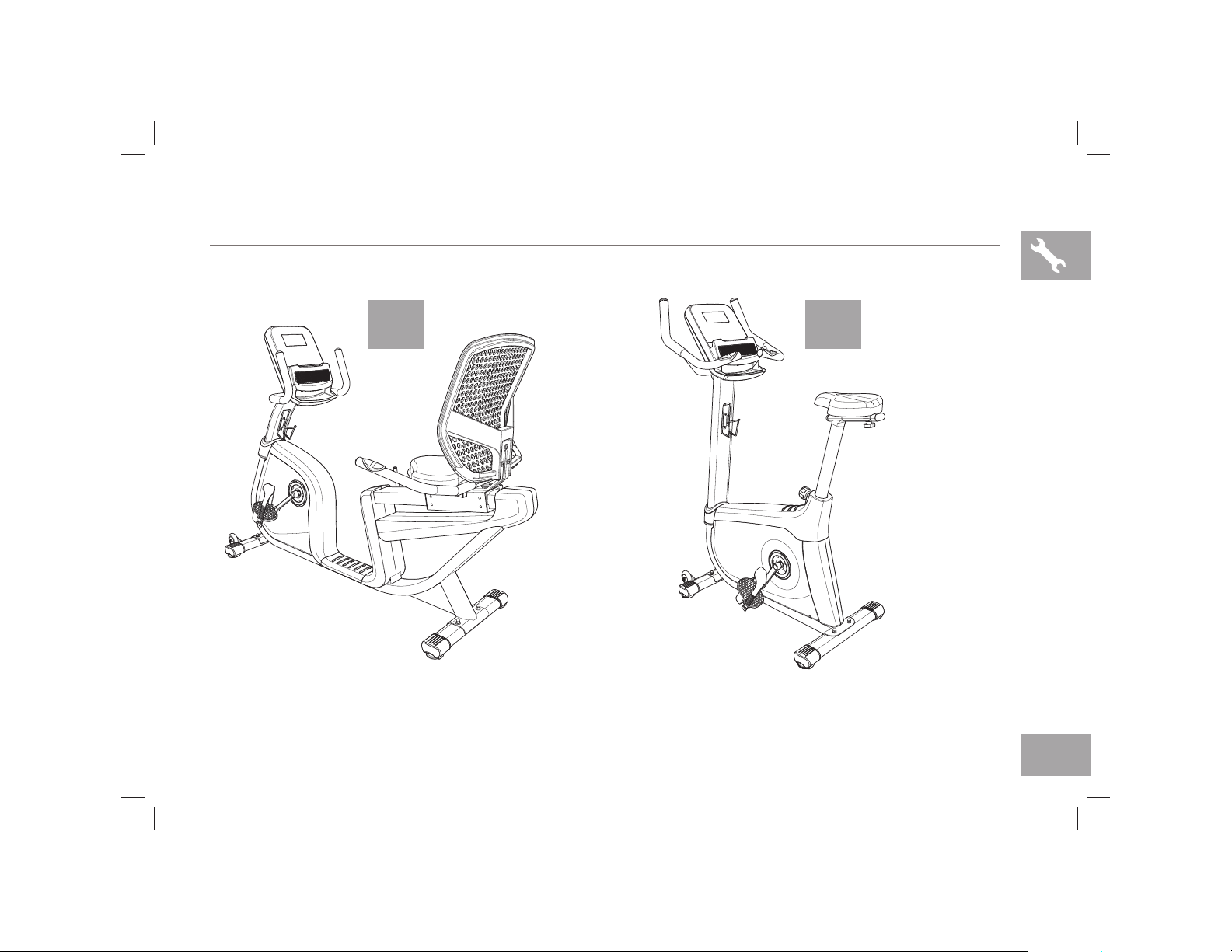
ASSEMBLY
7.3AR
page 16
7.3AU
page 16
AFG14_7.3AR_AU_OM_r1_5.indd 9 5/12/14 11:12 AM
10
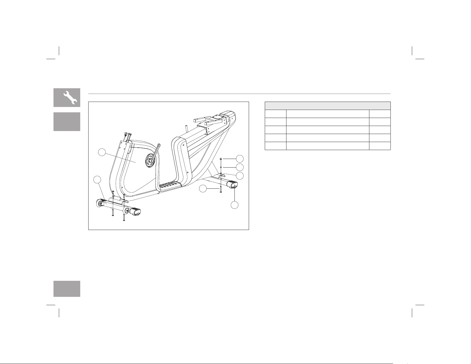
7.3AR ASSEMBLY STEP 1
A Open HARDWARE FOR STEP 1.
B Attach the FRONT STABILIZER TUBE (1) to the
BIKE FRAME (2) using 2 BOLTS (A), 2 FLAT
WASHERS (B), 2 SPRING WASHERS (C) and
2 NUTS (D).
C Attach the REAR STABILIZER TUBE (3) to the
BIKE FRAME (2) using 2 BOLTS (A), 2 FLAT
WASHERS (B), 2 SPRING WASHERS (C) and
2 NUTS (D).
2
1
D
C
B
3
A
7.3AR
HARDWARE FOR STEP 1
PART TYPE QTY
A BOLT 4
B FLAT WASHER 4
C SPRING WASHER 4
D NUT 4
AFG14_7.3AR_AU_OM_r1_5.indd 10 5/12/14 11:12 AM
11
7.3AR ASSEMBLY STEP 2
A Open HARDWARE FOR STEP 2.
B Slide CONSOLE MAST GROMMET (4) from the
bottom up the CONSOLE MAST (5).
C Attach CONSOLE CABLES (6) and carefully tuck
all cables into BIKE FRAME (1). Slide CONSOLE
MAST (5) into BIKE FRAME (1).
D Attach the CONSOLE MAST (5) using 4 BOLTS
(E), 4 SPRING WASHERS (C) and 4 FLAT
WASHERS (B) from the rear.
E Slide CONSOLE MAST GROMMET (4) down over
BIKE FRAME (1).
1
5
4
6
B
C
E
7.3AR
NOTE: Be careful not to pinch any wires while attaching the console mast.
HARDWARE FOR STEP 2
PART TYPE QTY
E BOLT 4
B FLAT WASHER 4
C SPRING WASHER 4
AFG14_7.3AR_AU_OM_r1_5.indd 11 5/12/14 11:12 AM
12
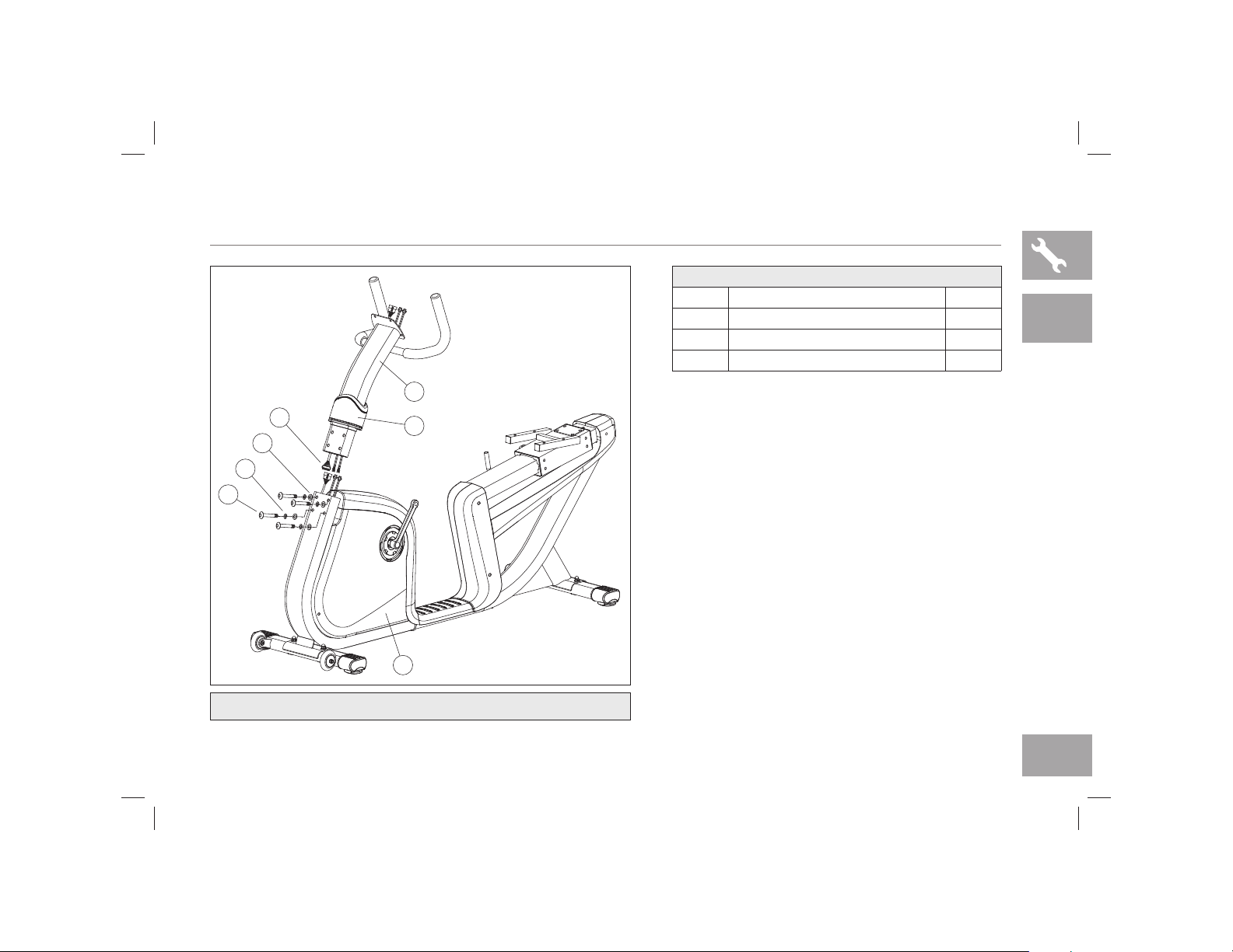
7.3AR ASSEMBLY STEP 3
* NOTE: There is no hardware for this step.
A Attach PEDAL STRAPS (7) to PEDALS (8).
B Attach the RIGHT PEDAL to the RIGHT CRANK
ARM, tightening it CLOCKWISE with the provided
13mm/15mm flat wrench.
C Attach the LEFT PEDAL (8) onto the LEFT
CRANK ARM (9), tightening it COUNTER-
CLOCKWISE with the provided 13mm/15mm flat
wrench. (NOTE: The left crank arm is reversed
threaded so it is very important that it is tightened
counter-clockwise. Tightening it the opposite way
can damage the pedal or the crank arm or both.)
D Connect the CONSOLE CABLES (6) and carefully
tuck them into the CONSOLE MAST (5).
E Attach the CONSOLE (10) to the CONSOLE
MAST (5) using the 4 PRE-ATTACHED SCREWS
(11) (The screws will have to be removed from the
console first).
10
7
8
11
5
9
8
6
7.3AR
NOTE: Be careful not to pinch any wires while attaching the console.
AFG14_7.3AR_AU_OM_r1_5.indd 12 5/12/14 11:12 AM

13
7.3AR
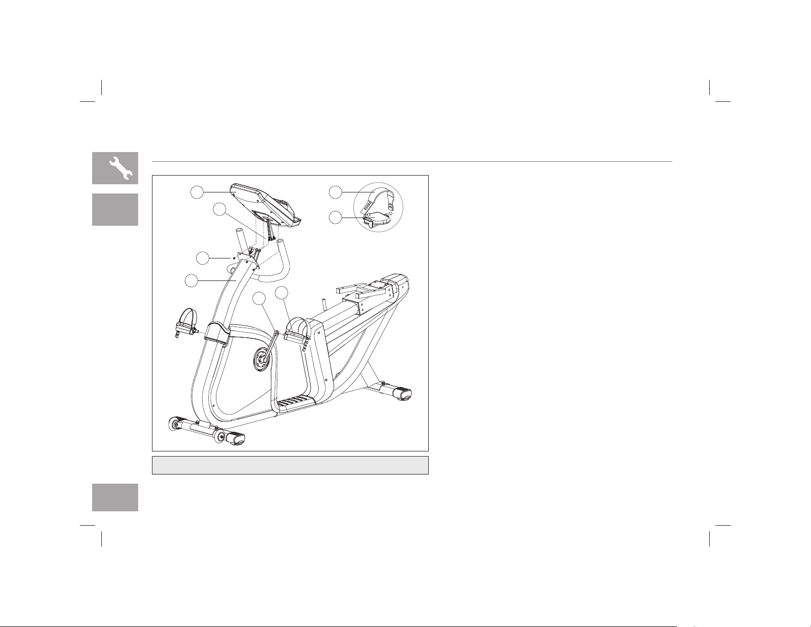
7.3AR ASSEMBLY STEP 4
15
5
I
F
12
C
B
14
13
E
C
L
A Open HARDWARE FOR STEP 4
B To attach the SEAT BACK BRACKET (12) to the
SEAT FRAME (13), insert 2 BOLTS (F), 2 SPRING
WASHERS (C) and 2 FLAT WASHERS (B) into
the rear-facing screw holes on the SEAT BACK
BRACKET (12).
C Attach the HANDLEBARS (14) to the front-facing
screw holes on the SEAT BACK BRACKET (12)
using 2 BOLTS (E), 2 SPRING WASHERS (C) and
2 ARC WASHERS (L).
D Attach the WATER BOTTLE HOLDER (15) to the
CONSOLE MAST (5) using 2 SCREWS (I).
HARDWARE FOR STEP 4
PART TYPE QTY
F BOLT 15 MM 2
B FLAT WASHER 2
C SPRING WASHER 4
E BOLT 50 MM 2
L ARC WASHER 2
I SCREW 2
AFG14_7.3AR_AU_OM_r1_5.indd 13 5/12/14 11:12 AM

14
16
13
B
J
7.3AR ASSEMBLY STEP 5
7.3AR
A Open HARDWARE FOR STEP 5
B Attach the SEAT (16) to the SEAT FRAME (13)
using 4 BOLTS (J) and 4 FLAT WASHERS (B).
HARDWARE FOR STEP 5
PART TYPE QTY
J BOLT 4
B FLAT WASHER 4
AFG14_7.3AR_AU_OM_r1_5.indd 14 5/12/14 11:12 AM

15
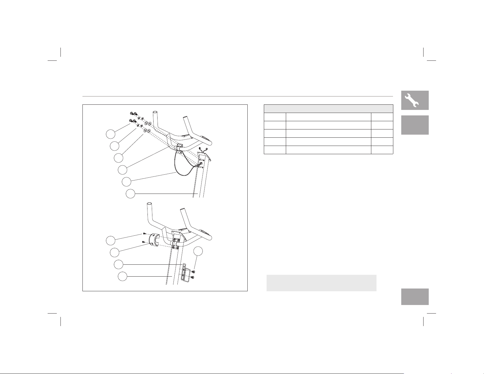
7.3AR ASSEMBLY STEP 6
A Open HARDWARE FOR STEP 6.
B Place SEAT BACK BRACKET PLATE (17) on the
inside of the mesh seat back mount. Align mesh
SEAT BACK (18) to SEAT BACK BRACKET (12).
C Attach mesh seat back to seat back bracket using
3 BOLTS (K) and 3 FLAT WASHERS (B) from the
rear and 3 FLAT WASHERS (B) and 3 NUTS (H)
on the other side of the seat back bracket plate.
D Attach SEAT CABLE (19) as shown. Plug in
POWER ADAPTER (20) as shown.
K
19
B
17
12
18
H
20
7.3AR
7.3AR ASSEMBLY COMPLETE!
HARDWARE FOR STEP 5
PART TYPE QTY
K BOLT 3
B FLAT WASHER 6
H NUT 3
AFG14_7.3AR_AU_OM_r1_5.indd 15 5/12/14 11:13 AM

16
7.3AU ASSEMBLY STEP 1
A Open HARDWARE FOR STEP 1.
B Attach the FRONT STABILIZER TUBE (1) to the
BIKE FRAME (2) using 2 BOLTS (A), 2 FLAT
WASHERS (B), 2 FLAT WASHERS (C) and
2 NUTS (D).
C Attach the REAR STABILIZER TUBE (3) to the
BIKE FRAME (2) using 2 BOLTS (A), 2 FLAT
WASHERS (B), 2 FLAT WASHERS (C) and
2 NUTS (D).
1
2
D
C
B
A
3
7.3AU
HARDWARE FOR STEP 1
PART TYPE QTY
A BOLT 4
B FLAT WASHER 4
C SPRING WASHER 4
D NUT 4
AFG14_7.3AR_AU_OM_r1_5.indd 16 5/12/14 11:13 AM
17
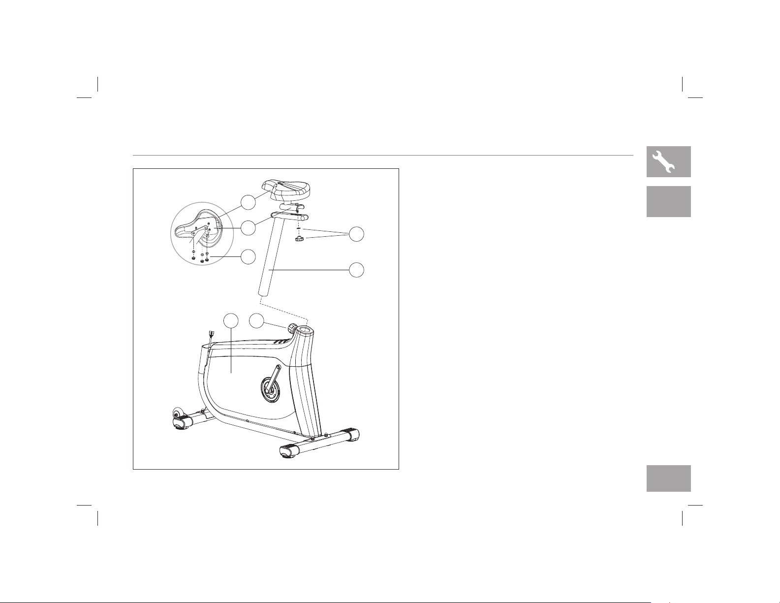
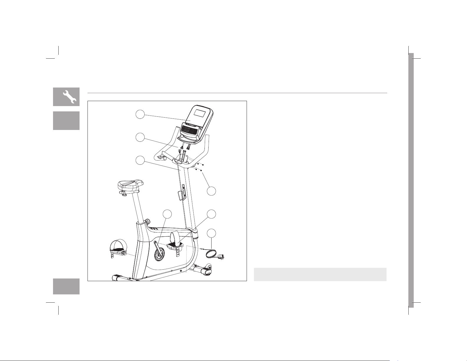
7.3AU ASSEMBLY STEP 2
* NOTE: There is no hardware for this step.
A Attach SEAT (4) to SEAT BASE (5) using 3
PRE-INSTALLED FLAT WASHERS AND
NUTS (6).
B Attach SEAT BASE (5) to SEAT POST
TUBE (7) using SEAT ADJUSTMENT
KNOB AND WASHER (8).
C Pull the SEAT HEIGHT ADJUSTMENT
KNOB (9) outward while sliding the SEAT
POST TUBE (7) into the BIKE FRAME (2).
7
8
6
5
4
2
9
7.3AU
AFG14_7.3AR_AU_OM_r1_5.indd 17 5/12/14 11:13 AM
18
7.3AU ASSEMBLY STEP 3
7.3AU
NOTE: Be careful not to pinch any wires
while attaching the console mast.
A Open HARDWARE FOR STEP 3.
B Slide CONSOLE MAST GROMMET (10) from the
bottom up the CONSOLE MAST (11).
C Attach CONSOLE CABLES (12) and carefully tuck
all cables into BIKE FRAME (2). Slide CONSOLE
MAST (11) into BIKE FRAME (2).
D Attach the CONSOLE MAST (11) using 4 BOLT
(F), 4 SPRING WASHERS (C) and 4 FLAT
WASHERS (B) from the rear.
E Slide CONSOLE MAST GROMMET (10) down
over BIKE FRAME (2).
2
12
10
F
C
B
11
HARDWARE FOR STEP 3
PART TYPE QTY
F BOLT 4
B FLAT WASHER 4
C SPRING WASHER 4
AFG14_7.3AR_AU_OM_r1_5.indd 18 5/12/14 11:13 AM
19
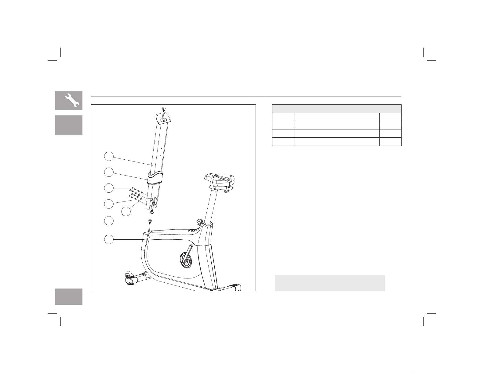
7.3AU ASSEMBLY STEP 4
A Open HARDWARE FOR STEP 4.
B Feed the HANDLBAR WIRES (13) through the
hole in the CONSOLE MAST (11) and out the top
of the CONSOLE MAST (11).
C Attach the HANDLEBARS (14) to the CONSOLE
MAST (11) using 4 BOLTS (G), 4 SPRING
WASHERS (C) and 4 FLAT WASHERS (B).
D Attach the HANDLEBAR COVER (15) to the
CONSOLE MAST (11) using 2 SCREWS (H).
E Attach the WATER BOTTLE HOLDER (16) to the
CONSOLE MAST (11) using 2 SCREWS (H).
11
13
14
B
C
G
11
H
16
15
H
t
7.3AU
NOTE: Be careful not to pinch any wires
while attaching the handlebars.
HARDWARE FOR STEP 4
PART TYPE QTY
G BOLT 4
B FLAT WASHER 4
C SPRING WASHER 4
H SCREW 4
AFG14_7.3AR_AU_OM_r1_5.indd 19 5/12/14 11:13 AM
20
7.3AU ASSEMBLY STEP 5
7.3AU
* NOTE: There is no hardware for this step.
A Attach the RIGHT PEDAL (17) to the RIGHT
CRANK ARM (18), tightening it CLOCKWISE with
the provided 13mm/15mm flat wrench.
B Attach the LEFT PEDAL onto the LEFT CRANK
ARM, tightening it COUNTER-CLOCKWISE with
the provided 13mm/15mm flat wrench. (NOTE: The
left crank arm is reversed threaded so it is very
important that it is tightened counter-clockwise.
Tightening it the opposite way can damage the
pedal or the crank arm or both.)
C Connect the CONSOLE CABLES (12) and
carefully tuck them into the CONSOLE MAST (11).
D Attach the CONSOLE (19) to the CONSOLE
MAST (11) using the 4 PRE-ATTACHED SCREWS
(20) (The screws will have to be removed from the
console first).
E Plug in POWER ADAPTER (21) as shown.
17
21
20
18
12
19
11
7.3AU ASSEMBLY COMPLETE!
AFG14_7.3AR_AU_OM_r1_5.indd 20 5/12/14 11:13 AM

21
BIKE OPERATION
This section explains how to use your bike’s console and programming.
The BASIC OPERATION section in the BIKE GUIDE has instructions for the following:
LOCATION OF THE BIKE
POWER/GROUNDING INSTRUCTIONS
SEAT POSITIONING
MOVING THE BIKE
LEVELING THE BIKE
USING THE HEART RATE FUNCTION
AFG14_7.3AR_AU_OM_r1_5.indd 21 5/12/14 11:13 AM
22
A
G
B
G
C
H H
D J
I F
E K
L
AFG14_7.3AR_AU_OM_r1_5.indd 22 5/12/14 11:13 AM

23
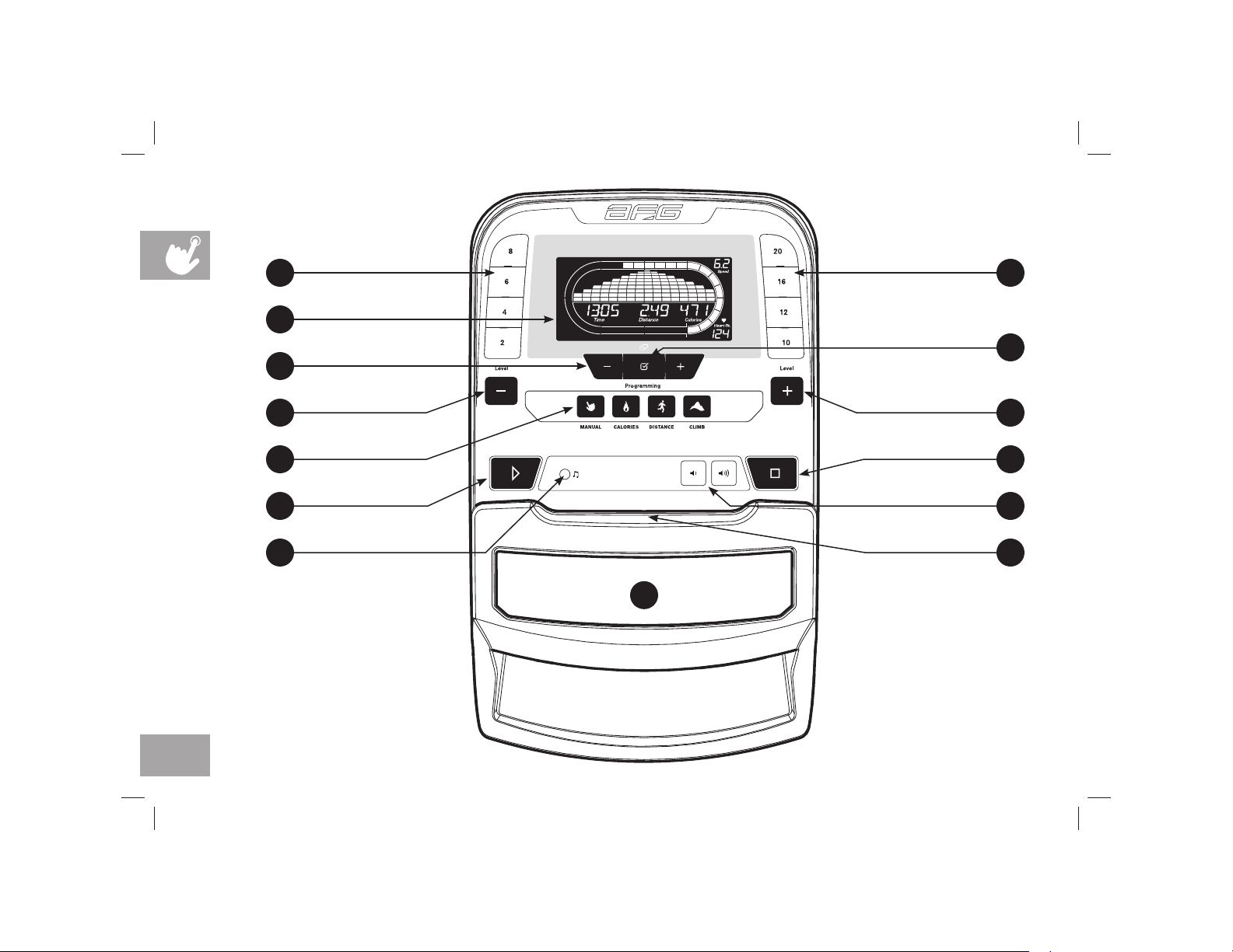
CONSOLE OPERATION
Note: There is a thin protective sheet of clear plastic on the overlay of the console that should be removed before use.
A) LCD DISPLAY WINDOW: time, distance, calories, watts, RPM, speed, resistance level, heart rate.
B) PROGRAMMING - /+ KEYS: Used to cycle through programs and user set up.
C)
ENTER / CHANGE DISPLAY: used to confirm selection or change display feedback during workout.
D) PROGRAM KEYS: press to select workout.
E) AUDIO IN JACK: plug your media player into the console using the included audio adaptor cable.
F) VOLUME: used to adjust volume up or down.
G) QUICK KEYS: used to reach desired resistance quickly.
H) LEVEL - /+ KEYS: used to adjust resistance level.
I)
GO / PAUSE: used to start workout, pause workout, and restart after pause.
J)
STOP / HOLD TO RESET: used to stop machine and also will reset machine when held down.
K) READING RACK: holds reading material.
L) SPEAKERS: plays music through speakers when connected to your media player
AFG14_7.3AR_AU_OM_r1_5.indd 23 5/12/14 11:13 AM

24
DISPLAY WINDOW
TIME: Shown as minutes : seconds. View the time remaining or the time elapsed in your
workout.
DISTANCE: Shown as miles. Indicates distance traveled or distance remaining during your
workout.
CALORIES: Total calories burned or remaining for your workout.
RPM: Rotations Per Minute
WATTS: Displays current user power output
SPEED: Shown as MPH. Indicates how fast the pedals are moving.
LEVEL: Shows the current level of resistance
HEART RATE: Shown as BPM (beats per minute). Used to monitor your heart rate (displayed
when contact is made with both pulse grips).
TRACK: Follows progress around a simulated track. Segments light up with every 12.5 meters
completed. One lap around the track is 400 meters (approximately 1/4 mile).
AFG14_7.3AR_AU_OM_r1_5.indd 24 5/12/14 11:13 AM

25
FINISHING YOUR WORKOUT
When your workout is complete, the console
will display “workout complete” and beep. Your
workout information will stay displayed on the
console for 30 seconds and then reset.
TO RESET THE CONSOLE
Hold STOP key for 3 seconds.
TO CLEAR CURRENT SELECTION
To clear the current program selection or screen,
hold the stop button for 3 seconds.
GETTING STARTED
1) Check to make sure no objects are nearby that will hinder the
movement of the exercise bike.
2) Plug in the power cord.
3) Enter user weight using -/+ and press ENTER
4) You have the following options to start your workout:
A) QUICK START UP
Simply press GO to begin working out.
Time, distance and calories will all count up from zero.
The resistance level will default to level 1.
B) SELECT A PROGRAM
1) Press desired PROGRAM BUTTON to select workout and
press ENTER.
2) Set goal level using -/+ and press ENTER.
3) Set resistance using -/+ and press ENTER.
4) Press
to begin workout.
NOTE: You can adjust the resistance level during your workout.
AFG14_7.3AR_AU_OM_r1_5.indd 25 5/12/14 11:13 AM
26
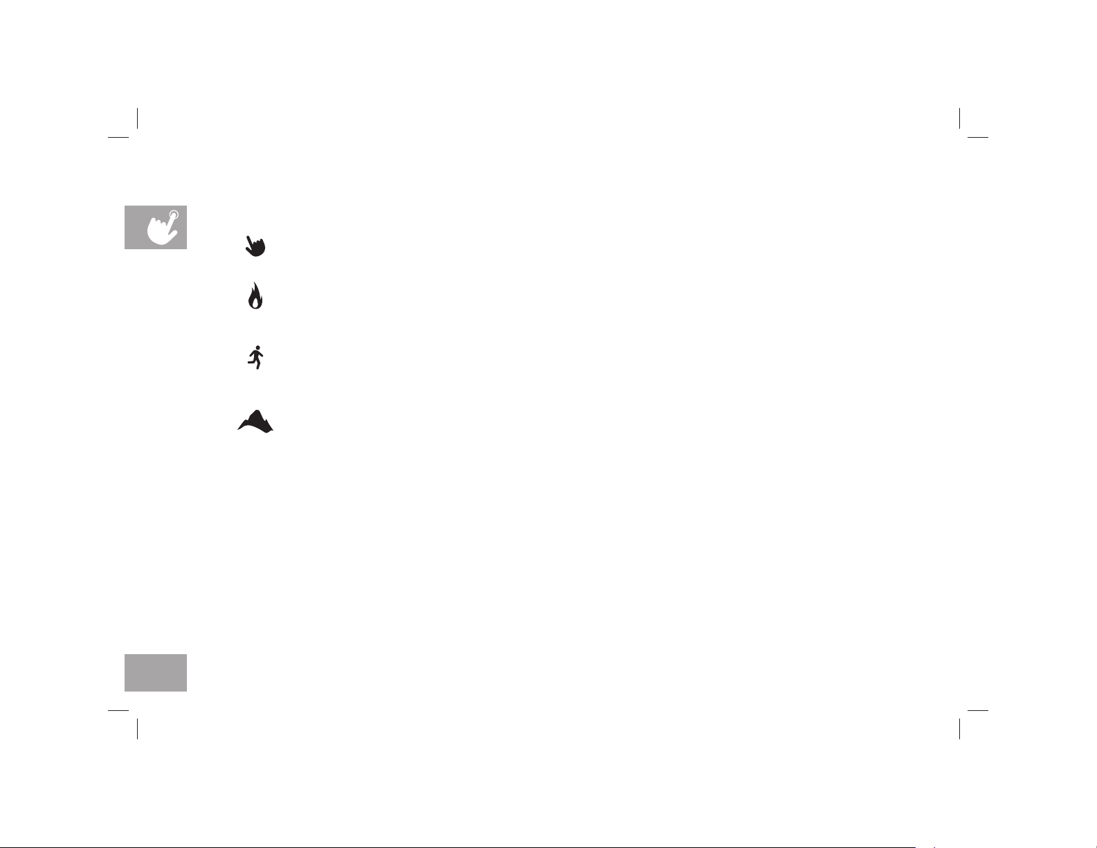
PROGRAM INFORMATION
MANUAL: Adjust your resistance level manually during your workout.
CALORIES: Set goals for burning calories with six workouts. Choose from 100, 200, 300, 400, 500, and 600
calorie burn workouts. User sets starting resistance. Calories burned are calculated using the resistance of
workout.
DISTANCE: Push yourself and go further during your workout with 10 distance workouts. Choose from 1 mile, 2
miles, 5k, 5 miles, 10k, 8 miles, 15k, 10 miles, 20k, and half marathon goals. User sets starting resistance.
CLIMB: Ascend world landmarks with six workouts based on vertical distance. User sets starting resistance.
Hollywood Sign – 1708 ft vertical distance
Empire State Building – 1250 ft vertical distance
Gateway Arch – 630 ft vertical distance
Space Needle – 605 ft vertical distance
Diamond Head Crater – 570 ft vertical distance
Washington Monument – 555 ft vertical distance
AFG14_7.3AR_AU_OM_r1_5.indd 26 5/12/14 11:13 AM

27
USING YOUR MEDIA PLAYER
1) Connect the included AUDIO ADAPTOR CABLE to the AUDIO IN JACK on the left of the console and the
headphone jack on your media player.
2) Use your media player buttons to adjust song settings.
3) Remove the AUDIO ADAPTOR CABLE when not in use.
ENERGY SAVER (STANDBY MODE)
This machine has a special feature called Energy Saver™ mode. This mode is NOT automatically activated.
When Energy Saver mode is activated, the display will automatically enter standby mode (Energy Saver mode) after
15 minutes of inactivity. This feature saves energy by disabling most power to the machine until a key is pressed on
the console. This feature can be turned on or off in the engineering menu.
To enter the engineering menu, press and hold the (+) LEVEL key and (–) LEVEL key for 3-5 seconds. Use the (-/+)
keys and ENTER key to navigate to P5 under ENG2. Press ENTER to select Energy Saver mode, use (-/+) keys to
select ENRGY SVE ON or OFF. Press and hold STOP for 3-5 seconds to exit ENG2. Press and hold STOP again for
3-5 seconds to exit the engineering menu.
AFG14_7.3AR_AU_OM_r1_5.indd 27 5/12/14 11:13 AM

28
AFG14_7.3AR_AU_OM_r1_5.indd 28 5/12/14 11:13 AM
 Loading...