

AFG 2.0AS, ZMK2000012 Owner’s Manual
HOME GYMASSEMBLY
AND USER'SGUIDE
CONGRATULATIONSand THANKYOUforyourpurchaseof thisAFGserieshomegym!
Whether your goal is to tone your muscles, increase your strength or simply enjoy a fuller, healthier
fifestyle, an AFGseries home gym can help you attain it - adding club-quafity performance to your
at-home workouts, with the ergonomics and innovative features you need to get stronger and healthier,
faster. Because we're committed to designing fitness equipment from the inside out, we use only the
highest quafity components. It's a commitment weback with one of the strongest warranty packages
in the industry.
Youwantexerciseequipmentthat offers the mostcomfort, the bestreliability and thehighest quality
in its class.
AnAFGhomegym derivers.
iiiiii _i I
[IBLE QF OQRTERTS
I I
Important Precautions 4
Assembly 5
Before You Begin 18
Conditioning Guidelines 19
Troubleshooting & Maintenance 24
Limited Warranty 26
CONTACTINFORMATION Back Panel
i i i
12/28/07 10:15:43 AM
iii i_iill il ii_ ii
5
_ i i iI
SAVETHESEINSTRUCtiONS
Read aft instructions before using this home gym, Basic precautions should always be followed, including the
following: Read aft instructions before using this home gym, It is the responsibility of the owner to ensure that
aft users of this home gym are adequately informed of aft warnings and precautions, Ifyou haveany questions
after reading this manual, contact customer service at the number listed on the back cover of this manual
, Closesupervisionis necessarywhenthis homegym is usedby,on, or near children,invalids, or disabled persons.
, Usethis appliance (or homegym) only for its intended useas describedin this manual Donot use attachments not
recommendedby the manufacturer.
o Neverdrop or insert any object into anyopening.
,, If you experienceany kind of pain, including but not limited to chest pains, nausea,dizziness, or shortnessof breath,
stop exercisingimmediatelyand consult yourphysician beforecontinuing.
,, Donot wearclothes that might catch onanypart of the homegym.
,, Always wearathletic shoeswhile using this equipment.
, Donotjump on the homegym.
, At no time should morethan onepersonbe on homegym while in operation.
, The home gym should not be used by persons weighing more than 300 pounds. Failure to comply win void the
warranty.
, The homegym is intended for in-home use only. Do not use this home gym in any commercial, rental, school or
institutional setting. Failureto complywill void the warranty.
IMPORTANT..READTHESESAFETYINSTRUCTIONSBEFOREUSE!
i_/i_/i!_ii_/i_ii_5_i_iii_:_i_ii_ii_ii!_i_ii_i_iii!_iii_iii_i__iii_/i_:_ii_ii_i_i:_i:iii/_iii_i_!ii_i_iii_i/_i_!i_iii!_ii_:ii_i_i_i_i_ii___i!_i_i_i:_iii_iiiiii_!_i_
i_51_i_i_i_:_iii_!_i_i!iii!i_i_ii_i_ii___i_iiii!__i_i_):_ii__i_ii_/i_iii_ii_!_i_i__i_i_iii_ii/ _i_i:_i_i_ii_iii___!:_i:i_!_i_!i_i_i_iii_i__i:i_i_i_i_ii_iii!_i_5_i___i_iii_/_iil
tofoflowtheassemblyinstructionscorrectlyand tomake sureaftpartsarefirmlYtightened.Iftheassembly
instru_tionsarenotfoMowedcorrect,_thehom_zymco.l_haveframePa_tsthat
seemlooseandmaycauseirritatinznoises,Thereshouldbenoside_to-_ideplayintheframeuprizhts,lf
there is any play in these areasl the home gym has not been proPerly assembled To prevent flama e to the
home correctiveactio's
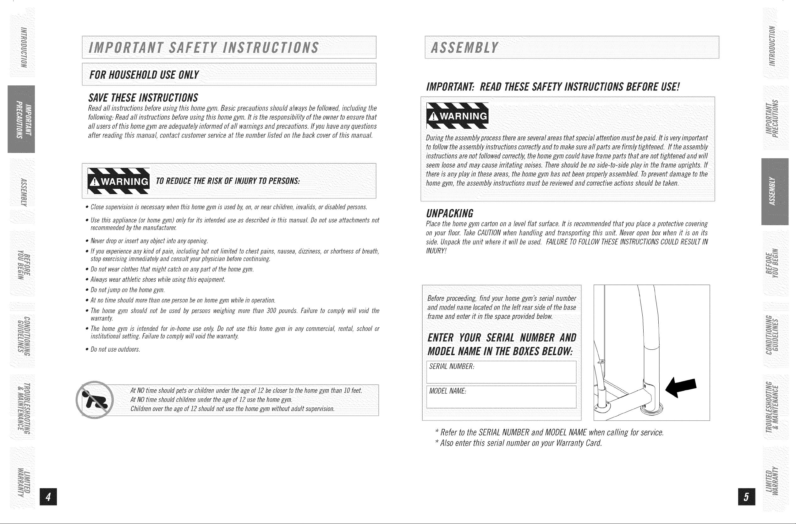
UNPACKING
Place the home gym carton on a level flat surface, It is recommended that you place a protective covering
on your floor, TakeCAUTIONwhen handling and transporting this unit. Never open box when it is on its
side, Unpack the unit where it win be used, FAILURETOFOLLOWTHESEINSTRUCTIONSCOULDRESULTIN
INJURY!
Before roceedin ,fin yo, hOme
anfl mofle! name Iocatef! on the left rear s!de of the base
frame add enter it in the space providefl below,
/
ii ¸ _
il__iii_i_i_i!I_ii_ii_!!_i_
i ii
,, Donot useoutdoors.
MODELNAMEIN OXES OW:
/
Refer to the SERIALNUMBERand MODELNAMEwhencallin_ for service.
Also enter this serial number onyour Warranty Card.
UPPERPULLEYASSEMBLY
_ i i iI
DUALFLOATINGPULLEYBRACKET
LATPULLDBWNBAR
LARGE"O" RING
CENTERSUPPORTFRAME
WATERBOTTLEHOLDER
CABLE"B"
SEATHEADPAD
HANDLES
RADIALARMADJUSTMENTPiN
SEATBACKPAD
SEATBACKADJUSTMENTKNOB
BICEPCURLBAR
SEATBOTTOMPAD
SEATWELDMENT
LEGEXTENSION/CURLDOWNTUBE
ADJUSTMENTBAR
SEATHEIGHTADJUSTMENTKNOB
FOAMROLLERS BASEFRAME
ADJUSTABLEFOOTPLATE > CABLE"B"
-- SINGLEFLOATINGPULLEYBRACKET
-SEATASSEMBLYSAFETYPiN
WEIGHTSHROUD
CABLE"C"
GUIDEROD
RADIALARMASSEMBLY
ACCENTPIECE
BAYONET
WEIGHTSELECTIONPiN
RIGHTSUPPORTFRAME
roo sINg UDfD ....
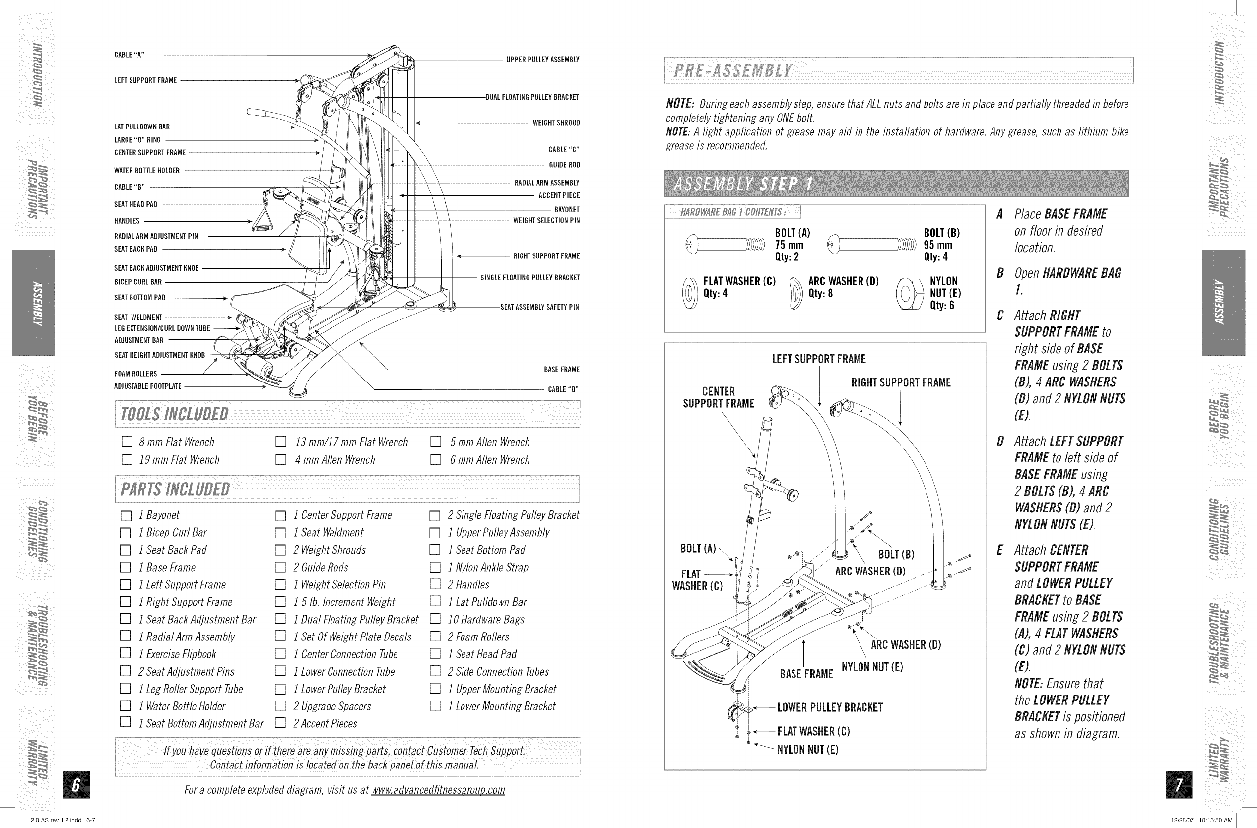
NOTE: Durin_ each assembly step, ensure that ALL nuts and bolts are in place and partially threaded in before
completely ti_htenin_ any ONEbolt,
/VOTE:A light application of grease may aid in the installation of hardware, Any grease, such as lithium bike
grease is recommended,
A
Place BASEFRAME
BOLT(A) BOLT(B)
_ 75rnrn _ _ 95rnrn
on floor in desired
location.
ii i iiii
/
Qty:2 Qty:4
B
OpenHARDWAREBAG
Qty:4 Qty:8 NUT(E)
FLATWASHER(C) _) ARCWASHER(D) (_NYLON
Qty:6
1.
C
AttachRIGHT
SUPPORTFRAMEto
right sideof BASE
LEFTSUPPORTFRAME
FRAMEusin_2 BOLTS
(B),4ARCWASHERS
CENTER
SUPPORTFRAME
i
(D)and2 NYLONNUTS
(E).
[] 8rnrnFlatWrench [] 13rnrn/17rnrnFlatWrench [] 5rnrnAIlenWrench
[] 19 rnrn Flat Wrench [] 4 rnrn Allen Wrench [] 6 rnrn Allen Wrench
[] 1 Bayonet [] 1 Center Support Frame [] 2 Single Floating Pulley Bracket
[] 1 Bicep Cuff Bar [] 1 Seat Weldment [] 1 UpperPulleyAssernbly
[] 1 Seat Back Pad [] 2 Weight Shrouds [] 1 Seat Bottom Pad
[] 1 Base Frame [] 2 Guide Rods [] 1 NylonAnkle Strap
[] 1 Left Support Frame [] 1 Weight Selection Pin [] 2 Handles
[] 1 Right Support Frame [] 1 5 Ib, Increment Weight [] 1 Lat Pulldown Bar
[] 1 Seat Back Adjustrnent Bar [] 1Dual FIoating Pulley Bracket [] l Ol-lardware Bags
[] 1 Radial Arrn Assernbly [] 1 Set Of Weight Plate Decals [] 2 Foarn Rollers
[] 1 ExerciseFlipbook [] 1 Center Connection Tube [] 1 Seat Head Pad
[] 2 Seat Adjustment Pins [] 1 Lower Connection Tube [] 2 Side Connection Tubes
[] 1 Leg Roller Support Tube [] 1 LowerPulley Bracket [] 1 Upper Mounting Bracket
[] 1 WaterBottle Holder [] 2 Upgrade Spacers [] 1 LowerMounting Bracket
[] 1 Seat Bottom Adjustment Bar [] 2 Accent Pieces
BASEFRAME
i i
' *--- LOWERPULLEYBRACKET
@
t ÷_ FLATWASHER(C)
° _ NYLONNUT(E)
i
ARCWASHER(D)
NYLONNUT(E)
D
AttachLEFTSUPPORT
FRAMEtoleft sideof
BASEFRAMEusin_
2 BOLTS(B),4 ARC
WASHERS(D)and2
NYLONNUTS(E).
E
AttachCENTER
SUPPORTFRAME
andLOWERPULLEY
BRACKETto BASE
FRAMEusin_2 BOLTS
(A),4 FLATWASHERS
(C)and2 NYLONNUTS
(E).
NOTE:Ensurethat
theLOWERPULLEY
BRACKETispositioned
as shown in dia_rarn.
il__iiii_ii!I_ii_ii_!!_i_
i ii
i / _ii
2.0 AS rev 1.2.indd 6-7
W
Contactinforrnationis locatedonthe backpanelof this manual.
Fora completeexplodeddiagram,visit usat www,advancedfitnessro_zoujzcorn
12/28/07 10:15:50 AM
A
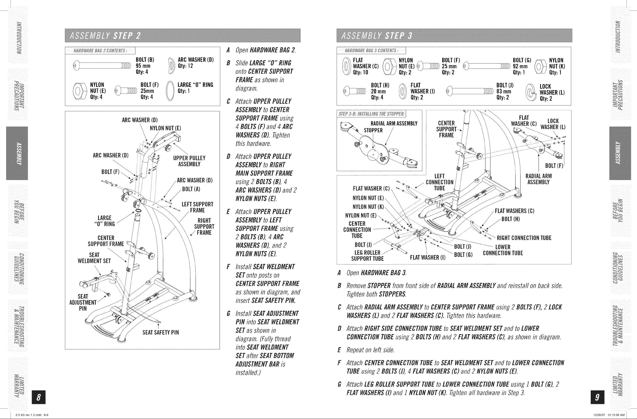
OpenHARDWAREBAGZ
iI_ ii_i i
_ i i iI
_ YLON
NUT(E)
Qty:4
ARCWASHER(D)
CENTER
SUPPORTFRAME
SEAT
WELDMENTSET \
\
SEAT
ADJUSTMENT/
PIN
BOLT(B) _ ARCWASHER(D)
95mm _ Qty:12
Qty:4
BOLT(F) _ LARGE"O"RING
_25mm Qty:l
Qty:4
V)
ARCWASHER(D)
NYLON NUT(E)
UPPER PULLEY
ASSEMBLY
ARCWASHER(D)
......_. LEFTSUPPORT
t
SEATSAFETYPiN
(A)
FRAME
RIGHT
SUPPORT
/FRAME
B
Slide LARGE"0" RING
onto CENTERSUPPORT
FRAMEas shownin
diagram.
C
AttachUPPERPULLEY
ASSEMBLYtoCENTER
SUPPORTFRAMEusing
4 BOLTS(F)and 4ARC
WASHERS(D). Tighten
this hardware.
D
Attach UPPERPULLEY
ASSEMBLYtoRIGHT
MAINSUPPORTFRAME
using2 BOLTS(B),4
ARC WASHERS(D)and2
NYLONNUTS(E).
E
AttachUPPERPULLEY
ASSEMBLYtoLEFT
SUPPORTFRAMEusing
2 BOLTS(B),4 ARC
WASHERS(D),and2
NYLONNUTS(E).
F
Install SEATWELDMENT
SETontoposts on
CENTERSUPPORTFRAME
as shown in diagram, and
insert SEATSAFETYPIN.
G
Install SEATAD]USTMENT
PINintoSEATWELDMENT
SETas shownin
diagram.(Fullythread
into SEATWELDMENT
SETafter SEATBOTTOM
AD]USTMENTBARis
installed.)
NYLON BOLT(F)
WASHER(C)
(_ FLAT
Qty:10
BOLT(H)
20 mm
Qty:4
RADIALARMASSEMBLY
NUT(E)_ 25 mm
Qty:2 Qty:2
WASHER(I)
(_ FLAT
Qty:2
CENTER
SUPPORT-_
FRAME
LEFT
CONNECTION
FLATWASHER
NYLONNUT(E)
NYLONNUT(K)\
NYLONNUT(E)\o.
CENTER
CONNECTION
TUBE
BOLT(J) BOLT(J)
LEGROLLER_ BOLT(G)
SUPPORTTUBE FLATWASHER (1)
--/ TUBE
BOLT(J) _ LOCK
83rnrn _ WASHER(L)
Qty:2 Qty:2
"-_..
RIGHTCONNECTIONTUBE
LOWER
CONNECTIONTUBE
BOLT(G)_ NYLON
92mm _NUT(K)
Qty:l Qty:1
FLAT
WASHER(C)WASHER(L)
RADIALARM
ASSEMBLY
LOCK
(c)
(H)
A OpenHARDWAREBAG3.
B RemoveSTOPPERfromfrontsideof RADIALARMASSEMBLYand reinstaflonbackside.
TightenbothSTOPPERS.
C AttachRADIALARMASSEMBLYto CENTERSUPPORTFRAMEusing2 BOLTS(F),2 LOCK
WASHERS(L)and2 FLATWASHERS(C). Tightenthis hardware.
D AttachRIGHTSIDECONNECTIONTUBEtoSEATWELDMENTSETand toLOWER
CONNECTIONTUBEusing2 BOLTS(H)and2 FLATWASHERS(C),as shownin diagram.
E Repeatonleft side.
F AttachCENTERCONNECTIONTUBEtoSEATWELDMENTSETandto LOWERCONNECTION
TUBEusing2 BOLTS(1),4 FLATWASHERS(C)and2 NYLONNUTS(E).
/
il__iii_i_i_i!I_ii_ii_!!_i_
i ii
i / _ii
2.0 AS rev 1.2.indd 8-9
G Attach LEGROLLERSUPPORTTUBEto LOWERCONNECTIONTUBEusing1BOLT(G),2
FLATWASHERS(I) and 1 NYLONNUT(K).Tightenall hardwarein Step3.
H
i(i /
12/28/07 10:15:56 AM
 Loading...