

AFG 18.1AXT Owner’s Manual

18.1AXT
Read the ELLIPTICAL GUIDE before using this OWNER'S MANUAL.
Lire le GUIDE D'UTILISATION DE UEXERCISEUR ELLIPTIQUE avant de se servir du present MANUEL DU PROPRIE_TAIRE.
Lea la GUiA DEL USUARIO DE LA MAQUINA ELiPTICA antes de usar este MANUAL DEL PROPIETARIO.

3 ENGLISH
44 FRANQAIS
86 ESPANOL


DANGER
TO REDUCE THE RISK OF ELECTRICAL SHOCK:
Always unplug the elliptical from the electrical outlet immediately after using, before cleaning, performing maintenance and putting on or taking
off parts.
,WARNING
TO REDUCE THE RISK OF BURNS, FIRE, ELECTRICAL SHOCK OR INJURY TO PERSONS:
• If you experience any kind of pain, including but not limited to chest pains, nausea, dizziness, or shortness of breath, stop
exercising immediately and consult your physician before continuing.
• When exercising, always maintain a comfortable pace. Do not sprint above 80 RPMs on this machine.
• To maintain balance, it is recommended to keep a grip on the handlebars while exercising, mounting or dismounting the machine.
• Do not turn pedal arms by hand.
• Make sure handlebars are secure before each use.
• Keep the topside of the foot support clean and dry.
• Care should be taken when mounting or dismounting the equipment. Before mounting or dismounting, move the pedal on the
mounting or dismounting side to its lowest position and bring the machine to a complete stop.
• Do not wear clothes that might catch on any part of the elliptical.
• Always wear athletic shoes while using this equipment.
• Do not jump on the elliptical.
• At no time should more than one person be on the elliptical while in operation.
• This elliptical should not be used by persons weighing more than the specified user capacity in the OWNER'S MANUAL
WARRANTY SECTION. Failure to comply will void the warranty.
• This elliptical is intended for in-home use only. Do not use this elliptical in any commercial, rental, school or institutional setting.
Failure to comply will void the warranty.
• Do not use elliptical in any location that is not temperature controlled, such as but not limited to garages, porches, pool rooms,
bathrooms, car ports or outdoors. Failure to comply will void the warranty.
• To prevent electrical shock, never drop or insert any object into any opening.
• Connect this exercise product to a properly grounded outlet only.

WARNING
TO REDUCE THE RISK OF BURNS, FIRE, ELECTRICAL SHOCK OR INJURY TO PERSONS:
• Keep power cord away from heated surfaces. Do not carry this unit by its supply cord or use the cord as a handle.
• Do not use other attachments that are not recommended by the manufacturer. Attachments may cause injury.
• Do not operate where aerosol (spray) products are being used or when oxygen is being administered.
• Use the elliptical only as described in the elliptical guide and owner's manual.
• Disconnect all power before servicing or moving the equipment. To clean, wipe surfaces down with soap and slightly damp cloth
only; never use solvents. (See MAINTENANCE)
• The elliptical should never be left unattended when plugged in. Unplug from outlet when not in use, and before putting on or
taking off parts.
• Do not operate under blanket or pillow. Excessive heating can occur and cause fire, electric shock, or injury to persons.
• At NO time should pets or children under the age of 13 be closer to the elliptical than 1 0 feet.
• At NO time should children under the age of 13 use the elliptical.
• Children over the age of 1 3 or disabled persons should not use the elliptical without adult supervision.
• Never operate the elliptical if it has a damaged cord or plug, if it is not working properly, if it has been dropped or damaged, or
immersed in water. Return the elliptical to a service center for examination and repair.
• To disconnect, turn all controls to the off position, then remove plug from outlet.
• Do not remove the console covers unless instructed by Customer Tech Support. Service should only be done by an authorized
service technician
It is essential that your elliptical is used only indoors, in a climate controlled room. If your elliptica! has been exposed to colder
temperatures or high moisture climates, it is strongly recommended that the elliptical is warmed UP to roo m temperature before ....
first time usel Fai!ure to do so may cause premature e!ectronic fai!urel
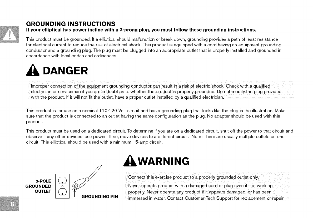
GROUNDING INSTRUCTIONS
If your elliptical has power incline with a 3-prong plug, you must follow these grounding instructions.
This product must be grounded. If a elliptical should malfunction or break down, grounding provides a path of least resistance
for electrical current to reduce the risk of electrical shock. This product is equipped with a cord having an equipment-grounding
conductor and a grounding plug. The plug must be plugged into an appropriate outlet that is properly installed and grounded in
accordance with local codes and ordinances.
DANGER
ImPr0Per c0nnection Of the equipment_gr0unding Conduct °r Can result in a ris k of e!ectric sh0ckl check Wit h a qualified
electricia n Or serviceman if you ar e in doubt as to whether the product is Properly grounded. Donot modify the plug provided .......
with the product. If it wi!l not fit the outlet, have a proper outlet installed by a qualified electrician,
This product is for use on a nominal 110-120 Volt circuit and has a grounding plug that looks like the plug in the illustration. Make
sure that the product is connected to an outlet having the same configuration as the plug. No adapter should be used with this
product.
This product must be used on a dedicated circuit. To determine if you are on a dedicated circuit, shut off the power to that circuit and
observe if any other devices lose power. If so, move devices to a different circuit. Note: There are usually multiple outlets on one
circuit. This elliptical should be used with a minimum 15-amp circuit.
WARNING
3-POLE
GROUNDED
OUTLET
_dDING PIN
ConneCt t his exercise pi0duct tO a prOPerly grounded Outlet 0nlyl
Never 0Perate Pr0duct with a damaged €0id or p!ug even if it is W0rking
properly. Never 0Perate any PrOduct if it appears damaged, or has been
immersed in waterl Contact customer Tech SupPOrt for replacement Or repair,

7
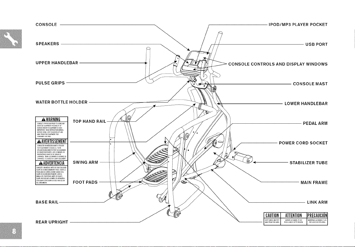
CONSOLE IPOD/MP3 PLAYER POCKET
SPEAKERS
UPPER HANDLEBAR
PULSE GRIPS
WATER BOTTLE HOLDER
_WARNING
CONSULT_PH¥_ICI_NP,IORTOU_ING_N¥
EXERCISEEQUIPMENT_SSIBlU_OF
SERIOUSINJU,¥IfEQUIPM_ISUSED
IMPROPERL_RE_DINSTRUC_ONM_NU_L
BEFO,EUSINGKEEPCHILD,ENOFFEND
_¥ roOMTHISEQUIPM_NTFOR
CONSUME,USEONLY
_,AVERTISSEMENT
_ONSU_TERUNM_OECIN_W_0U_LISE,
TOU_E_U_EMEN__E×E,C_CETOU_
U_US_T_ON_N_ORREBTEPE_OCC_ON_R
L_PP_,E_L_ LU_EOUCUE,T_ULEMENT
'_ADVERTENCIA
E_U__ U__NCOR,ECT_,Er__EREL
_EL®NSUM_O,
TOP HAND
SWING ARM --
FOOT PADS --
BASE RAIL
USB PORT
CONSOLE CONTROLS AND DISPLAY WINDOWS
CONSOLE MAST
LOWER HANDLEBAR
PEDALARM
POWER CORD SOCKET
STABILIZERTUBE
MAIN FRAME
LINK ARM
REAR UPRIGHT
P_ED_LO_NDECEdERE_ON
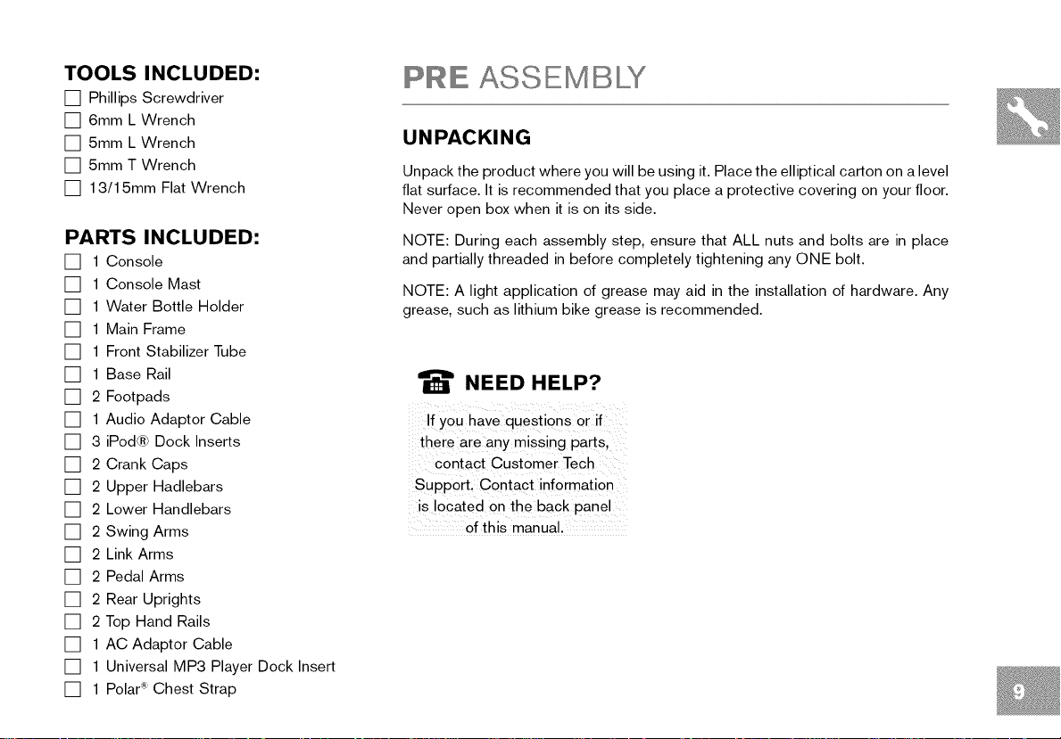
TOOLS INCLUDED:
[] Phillips Screwdriver
[] 6mm L Wrench
[] 5mm L Wrench
[] 5mm T Wrench
[] 1 3/1 5mm Flat Wrench
PARTS INCLUDED:
[] 1 Console
[] 1 Console Mast
[] 1 Water Bottle Holder
[] 1 Main Frame
[] 1 Front Stabilizer Tube
[] 1 Base Rail
[] 2 Footpads
[] 1 Audio Adaptor Cable
[] 3 iPod® Dock Inserts
[] 2 Crank Caps
[] 2 Upper Hadlebars
[] 2 Lower Handlebars
[] 2 Swing Arms
[] 2 Link Arms
[] 2 Pedal Arms
[] 2 Rear Uprights
[] 2 Top Hand Rails
[] 1 AC Adaptor Cable
[] 1 Universal MP3 Player Dock Insert
[] 1 Polar :_Chest Strap
PRE ASSEMBLY
UNPACKING
Unpack the product where you will be using it. Place the elliptical carton on a level
flat surface. It is recommended that you place a protective covering on your floor.
Never open box when it is on its side.
NOTE: During each assembly step, ensure that ALL nuts and bolts are in place
and partially threaded in before completely tightening any ONE bolt.
NOTE: A light application of grease may aid in the installation of hardware. Any
grease, such as lithium bike grease is recommended.
_' NEED HELP?
If you hav e questions or if
there are any missing part s,
contact Customer Tech
support, Contact information
is located on the back panel
Of this manual.
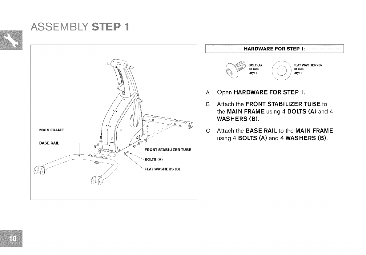
ASSEMBLY STEP 1
HARDWARE FOR STEP 1: ]
20 mm 20 mm
_ BOLT(A) _> FLATWASHER(B)
Qty: 8 Qty: 8
A Open HARDWARE FOR STEP 1.
B Attach the FRONT STABILIZER TUBE to
the MAIN FRAM E using 4 BOLTS (A) and 4
WASHERS (B).
MAiN FRAME
C Attach the BASE RAIL to the MAIN FRAME
using 4 BOLTS (A) and 4 WASHERS (B).
FRONT STABILIZER TUBE
_ BOLTS (A)
\ FLAT WASHERS (B)
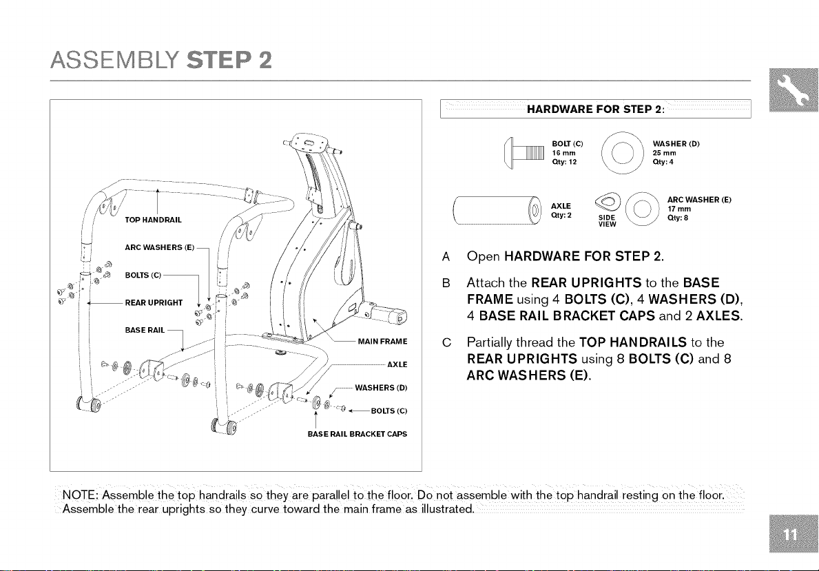
ASSEMBLY STEP 2
HARDWARE FOR STEP 2: ]
BOLT (C) WASHER (D)
16 mm 25 mm
Qty: 12 Qty: 4
TOP HANDRAIL
ARC WASHERS (E) _ / /
AXLE 17 mm
Qty: 2 SIDE Qty: 8
A Open HARDWARE FOR STEP 2.
__ ARC WASHER (E)
VIEW
B Attach the REAR UPRIGHTS to the BASE
FRAME using 4 BOLTS (C), 4 WASHERS (D),
4 BASE RAIL BRACKET CAPS and 2 AXLES.
C
Partially thread the TOP HAN DRAI LS to the
AXLE
REAR UPRIGHTS using 8 BOLTS (C) and 8
ARC WASHERS (E).
j ........ WASHERS (D)
l (C)
BASE RAIL BRACKET CAPS
NOTE:Assemble the top handrails So they are parallel to the floorl Do not assemble With the top handrail resting on the floor.
Assemble the rear uprights so they curve toward the main frame as illustrated.
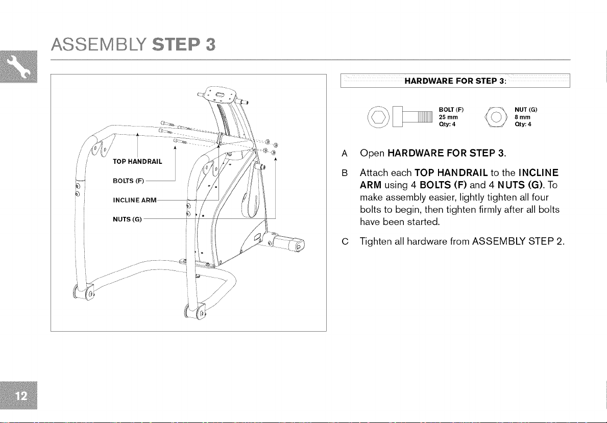
ASSEMBLY STEP 3
HARDWARE FOR STEP 3: ]
TOP HANDRAIL
BOLTS (F)
INCLINE
(__ BOLT (F) O NUT (G)
A
Open HARDWARE FOR STEP 3.
B
Attach each TOP HANDRAIL to the INCLINE
f
ARM using 4 BOLTS (F) and 4 NUTS (G). To
25 mm 8 mm
Qty: 4 Qty: 4
make assembly easier, lightly tighten all four
bolts to begin, then tighten firmly after all bolts
have been started.
I
C Tighten all hardware from ASSEMBLY STEP 2.
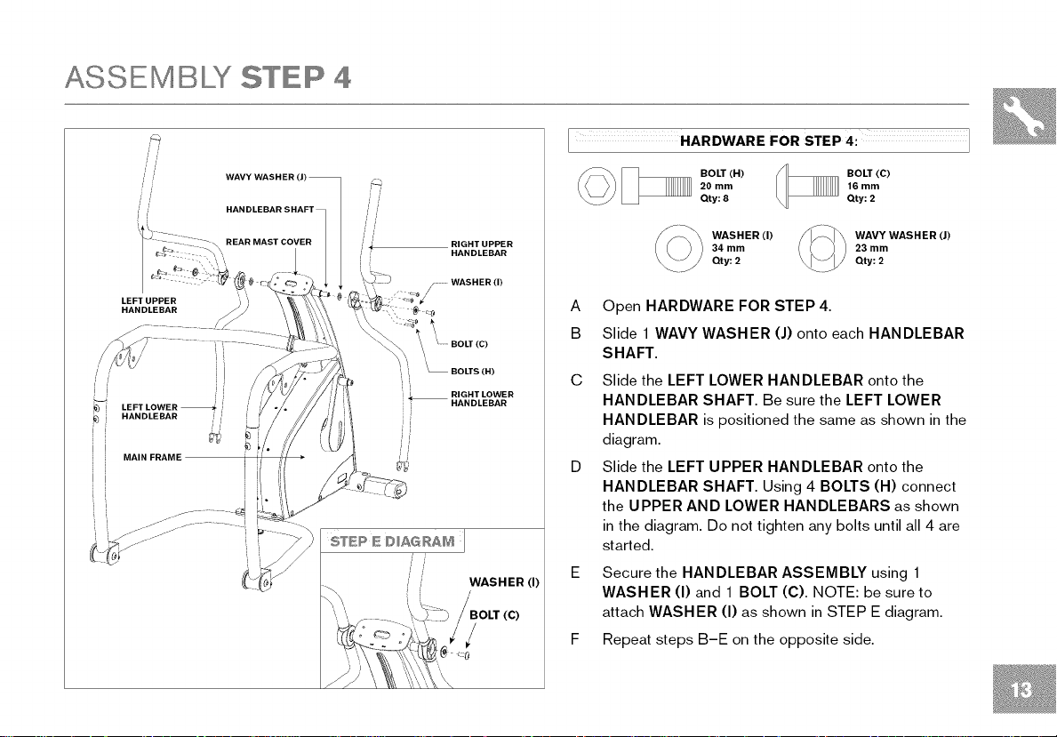
ASSEMBLY STEP 4
//
/ /
LEFT LOWER
HANDLEBAR /
6%
__ OLT (H)
ZZSN
\ REAR MAST COVE_-- / f
RIGHT UPPER
HANDLEBAR
WASHER(I)
HARDWARE FOR STEP 4: ]
20 mm
Qty: 8
WASHER (I) WAVY WASHER (J)
34 mm 23 mm
Qty: 2 Qty: 2
BOLT (C)
16 mm
Qty: 2
A Open HARDWARE FOR STEP 4.
BOLT(C)
B Slide 1 WAVY WASHER (J) onto each HANDLEBAR
SHAFT.
_ BOLTS (H)
i
i i RIGHT LOWER
HANDLEBAR
G Slide the LEFT LOWER HANDLEBAR onto the
HANDLEBAR SHAFT. Be sure the LEFT LOWER
HANDLEBAR ispositioned the same as shown in the
diagram.
D Slide the LEFT UPPER HANDLEBAR onto the
HANDLEBAR SHAFT. Using 4 BOLTS (H) connect
the UPPER AND LOWER HANDLEBARS as shown
inthe diagram. Do not tighten any bolts untilall 4 are
started.
E Secure the HANDLEBAR ASSEMBLY using1
WASHER (I) and 1 BOLT (C). NOTE: be sure to
attach WASHER (I) as shown inSTEP E diagram.
F Repeat steps B-E on the opposite side.
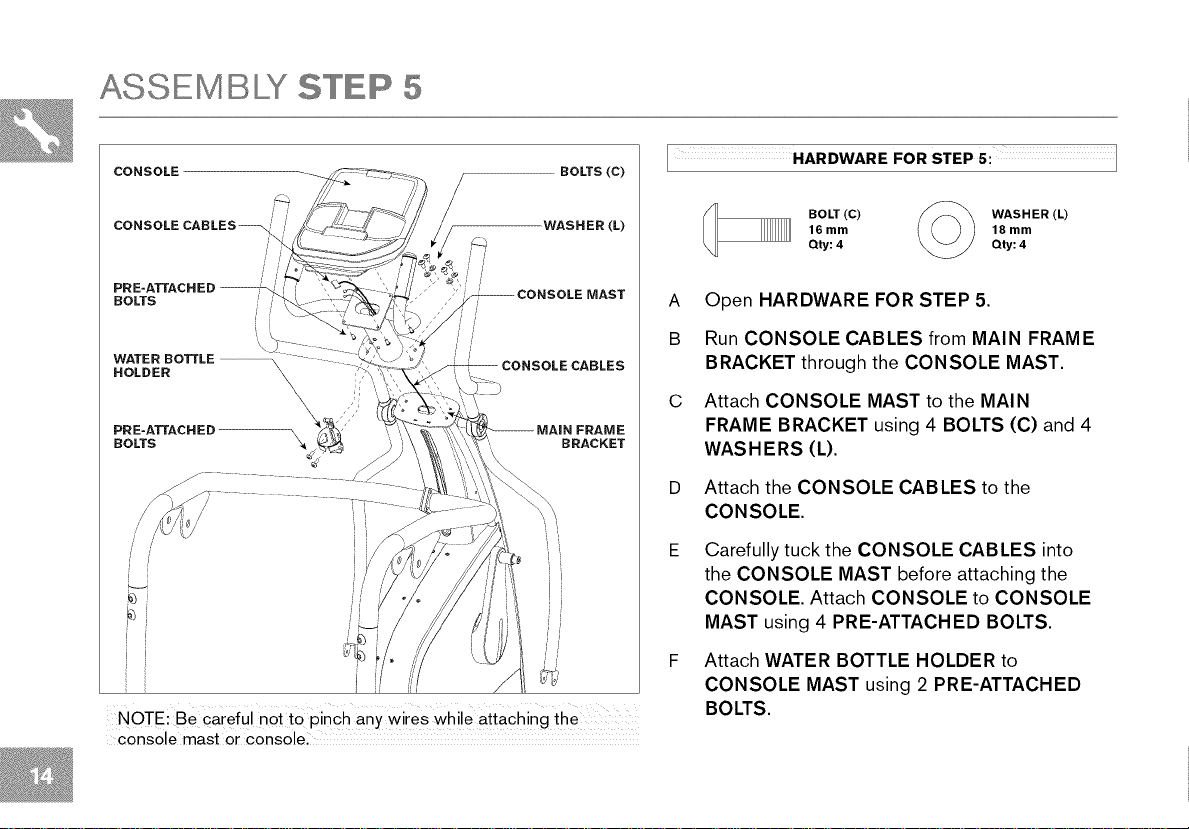
ASSEMBLY STEP 5
CONSOLE
CONSOLECABLES_
WASHER (L)
/
//
/ /
/
PRE-ATTACH ED --
BOLTS /
WATER BOTTLE / /
HOLDER
PRE-ATTACH ED _ FRAME
BOLTS _ BRACKET
NOTE: Be careful not to pinch any wires while attaching the
console mast or console,
i
HARDWARE FOR STEP 5: ]
BOLT (C) fF_\ WASHER (L)
Qty: 4 Qty: 4
16 mm _ 18 mm
A Open HARDWARE FOR STEP 5.
B Run CONSOLE CABLES from MAIN FRAME
BRACKET through the CONSOLE MAST.
C Attach CONSOLE MAST to the MAIN
FRAME BRACKET using 4 BOLTS (C) and 4
WASHERS (L).
Attach the CONSOLE CABLES to the
CONSOLE.
Carefully tuck the CONSOLE CABLES into
the CONSOLE MAST before attaching the
CONSOLE. Attach CONSOLE to CONSOLE
MAST using 4 PRE-ATTACHED BOLTS.
Attach WATER BOTTLE HOLDER to
CONSOLE MAST using 2 PRE-ATTACHED
BOLTS.
ASSEMBLY STEP 8
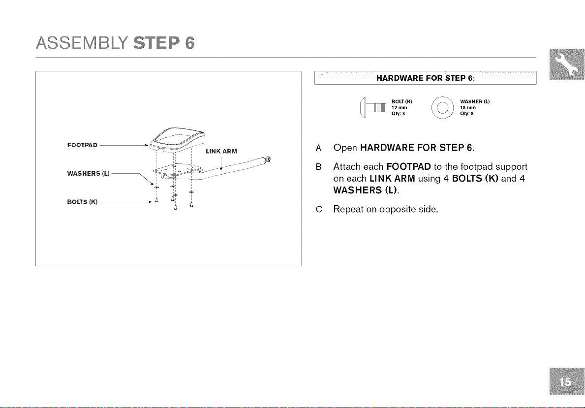
HARDWARE FOR STEP 6: ]
FOOTPAD )
" _i_:_,>Ji UNKARM
12 mm
BOLT (K)
Qty: 8
A
Open HARDWARE FOR STEP 6.
B
Attach each FOOTPAD to the footpad support
WASHER (L)
18 mm
Qty: 8
on each LINK ARM using 4 BOLTS (K) and 4
WASHERS (L).
C Repeat on opposite side.
ASSEMBLY STEP "7
WASHER (P)
PEDAL ARM
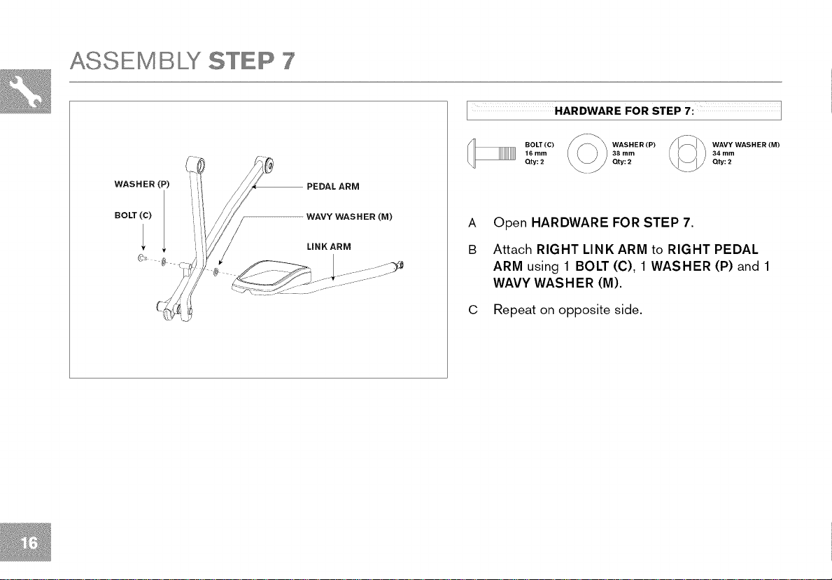
HARDWARE FOR STEP 7: ]
BOLT(C) WASHER (P) I _ WAVY WASHER (M)
16 mm 38 mm 34 mm
Qty: 2 Qty: 2 Qty: 2
©-
BOLT(c)
WAVY WASHER (M)
LINKARM
A Open HARDWARE FOR STEP 7.
B Attach RIGHT LINK ARM to RIGHT PEDAL
ARM using 1 BOLT (C), 1 WASHER (P) and 1
WAVY WASHER (M).
C Repeat on opposite side.
ASSEMBLY STEP 8
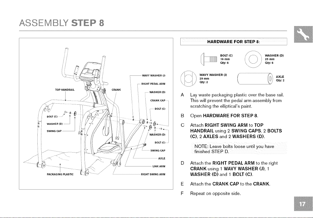
HARDWARE FOR STEP 8: ]
BOLT (C) WASHER (D)
16 mm 25 mm
Qty: 6 Qty: 6
TOP HANDRAIL
WAVY WASHER (J)
RIGHT PEDAL ARM
/' //
/ /' BOLT (C)
/I...................SWING CAP
//
/
! .............................................................AXLE
/
/
WASHER (D)
CRANK CAP .....
BOLT (C)
,/ WASHER (D)
LINK ARM
WAVY WASHER (J) AXLE
29 mm
Qty: 2 Qty: 2
A
Lay waste packaging plastic over the base rail.
This will prevent the pedal arm assembly from
scratching the elliptical's paint.
B
Open HARDWARE FOR STEP 8.
C
Attach RIGHT SWING ARM to TOP
HANDRAIL using 2 SWING CAPS, 2 BOLTS
(C), 2 AXLES and 2 WASHERS (D).
NOTE: Leave bo!ts !00Se unti! YOUhave
finished STEP D.
Attach the RIGHT PEDAL ARM to the right
CRANK using 1 WAVY WASHER (J), 1
WASHER (D) and 1 BOLT (C).
E Attach the CRAN K CAP to the CRAN K.
F Repeat on opposite side.
ASSEMBLY STEP 9
//
//
i i
WASHER LOWER HANDLEBAR
BOLT (N)
iJ
SPACER
LINK ARM
ROD BEARING SHAFT
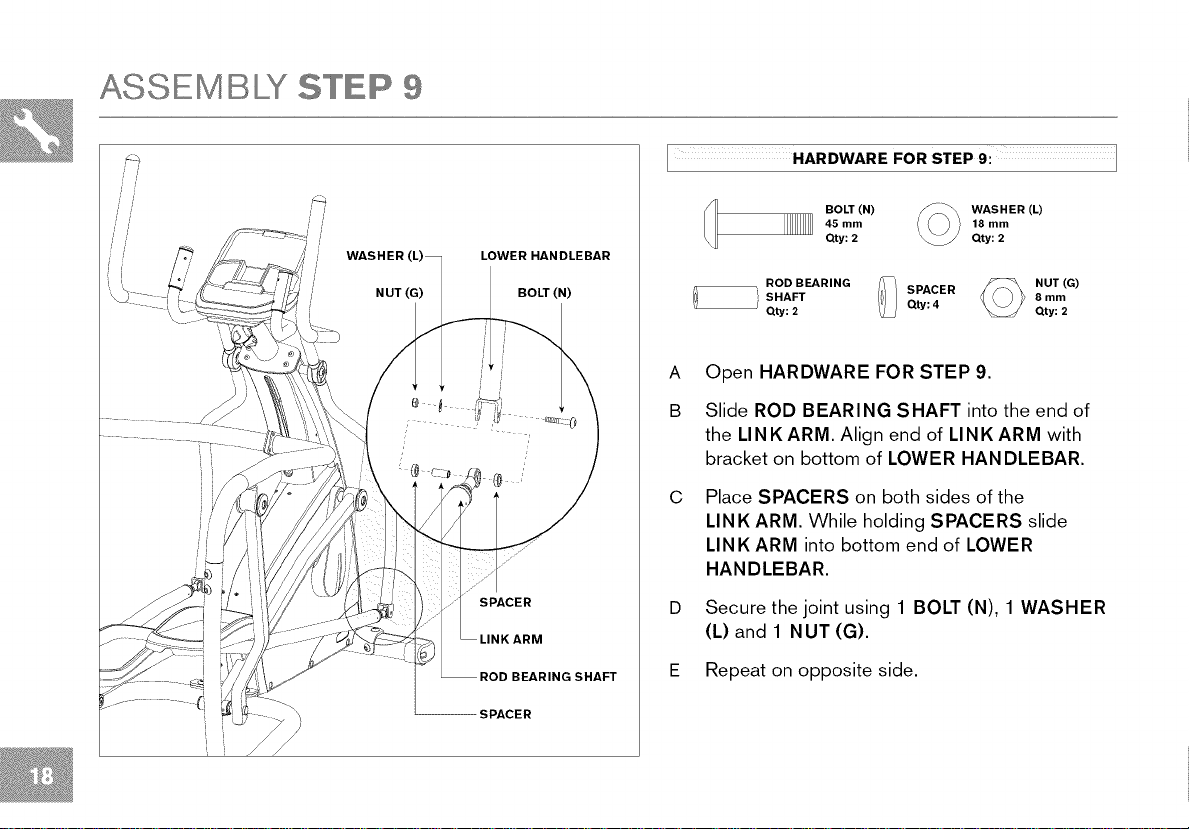
HARDWARE FOR STEP 9: ]
BOLT (N)
45 mm
Qty: 2
ROD BEARING SPACER _ NUT (G)
SHAFT 8 mm
Qty: 2 Qty: 4
WASHER (L)
18 mm
Qty: 2
Qty: 2
A Open HARDWARE FOR STEP 9.
B Slide ROD BEARING SHAFT into the end of
the LINKARM. Align end of LINKARM with
bracket on bottom of LOWER HAN DLEBAR.
C Place SPACERS on both sides of the
LINK ARM. While holding SPACERS slide
LINK ARM into bottom end of LOWER
HANDLEBAR.
Secure the joint using 1 BOLT (N), 1 WASHER
(L) and 1 NUT (G).
E Repeat on opposite side.
SPACER
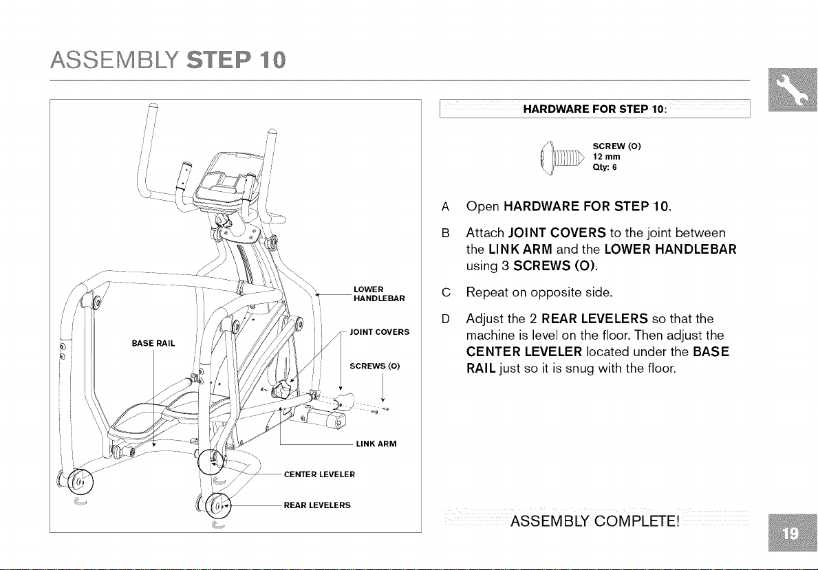
ASSEMBLY STEP lO
HARDWARE FOR STEP 10:1
//
//
SCREW (O)
12 mm
qty: 6
A Open HARDWARE FOR STEP 10.
B Attach JOINT COVERS to the joint between
the LINK ARM and the LOWER HANDLEBAR
using 3 SCREWS (O).
LOWER
HANDLEBAR
C Repeat on opposite side.
D Adjust the 2 REAR LEVELERS so that the
COVERS
machine is level on the floor. Then adjust the
CENTER LEVELER located under the BASE
SCREWS (0)
LINK ARM
LEVELERS
RAIL just so it is snug with the floor.


O
• um_
I_TAXT
eeeeeeeeeeeeee edi_t_
eeeeeeeeeeeeee
eeeeeeeeeeeeee
.............. B.B;B.B.
eeeeeeeeeeeeee
eeeeeeeeeeeeee
eeeeeeeeeeeeee e_io_
eeeeeeeeeeeeee
eeeeeeeeeeeeee _
eeeeeeeeeeeeee
• r_m
O
€_
0
O
0
Nike + iPod _A_
0 0 0
ipo_oootro,_
1
O
O
0
O
O
O_

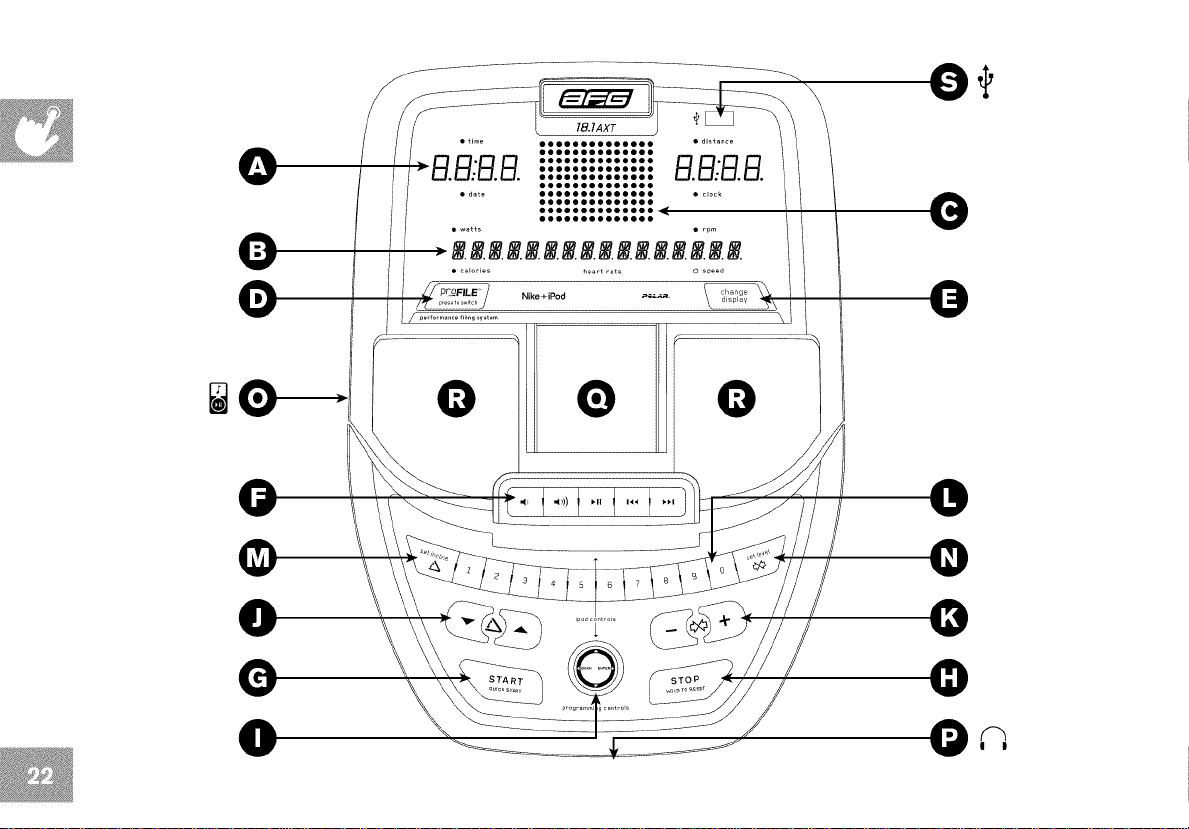
CONSOLE OPERATION
Note: There is a thin protective sheet of clear plastic on the overlay of the console that should be removed before use.
A) LED DISPLAY WINDOWS: time, distance, date and clock.
B) ALPHANUMERIC DISPLAY WINDOW: displays watts, calories, rpm, heart rate, speed and PROFILE TM display information.
C) WORKOUT PROFILE DISPLAY: displays workout level and progress.
D) PROFILE TM BUTTON: used to scroll through PROFILE TM display modes. User must be selected before pressing.
E) CHANGE DISPLAY BUTTON: used to scroll through display modes. Press to change display feedback during workout.
F) IPOD® CONTROLS: press to adjust your attached iPod® audio settings.
G) START: press to begin exercising, start your workout or resume exercising after pause.
H) STOP: press to pause/end your workout. Hold for 3 seconds to reset the console.
I) IPOD®/PROGRAMMING BUTTON: used to select program, level and time, and other options.
Used to control iPod® (during workout only).
J) INCLINE _,A KEYS: press to adjust incline in 50/0 increments.
K) RESISTANCE ÷ / - KEYS: press to adjust resistance.
L) QUICK ADJUST KEYPAD: used to reach desired resistance or incline more quickly.
M) SET INCLINE KEY: used to change incline to level entered into keypad.
N) SET LEVEL KEY: used to change resistance to level entered into keypad.
O) AUDIO IN: plug your cd / mp3 player into the console using the included audio adaptor cable.
P) AUDIO OUT/HEADPHONE JACK: plug your headphones into this jack to listen to your music through the headphones.
Q) IPOD® DOCKING STATION: used to dock and charge your iPod® (not included).
R) SPEAKERS: music plays through speakers when your cd/mp3 player is connected to the console.
S) USB PORT: used for software updates.
• time
• distance
B:32
I
date
oooooooooooooo
watts
oooooooooooooo
ooooooo
oooooooooo
oooooooooooo
3.un-1,
• calories
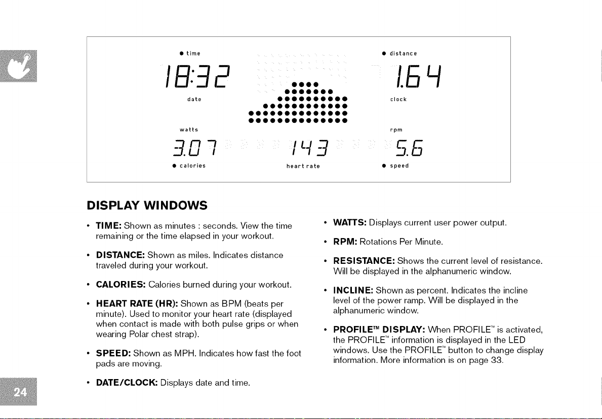
DISPLAY Wl NDOWS
• TIME: Shown as minutes : seconds. View the time
remaining or the time elapsed in your workout.
• DISTANCE: Shown as miles. Indicates distance
traveled during your workout.
• CALORIES: Calories burned during your workout.
• HEART RATE (HR): Shown as BPM (beats per
minute). Used to monitor your heart rate (displayed
when contact is made with both pulse grips or when
wearing Polar chest strap).
• SPEED: Shown as MPH. Indicates how fast the foot
pads are moving.
oooo
l.S
clock
rpm
• speed
• WATTS: Displays current user power output.
• RPM: Rotations Per Minute.
• RESISTANCE: Shows the current level of resistance.
Will be displayed in the alphanumeric window.
• INCLINE: Shown as percent. Indicates the incline
level of the power ramp. Will be displayed in the
alphanumeric window.
PROFILE TM DISPLAY: When PROFILE TM is activated,
the PROFILE TM information is displayed in the LED
windows. Use the PROFILE TM button to change display
information. More information is on page 33.
• DATE/CLOCK: Displays date and time.
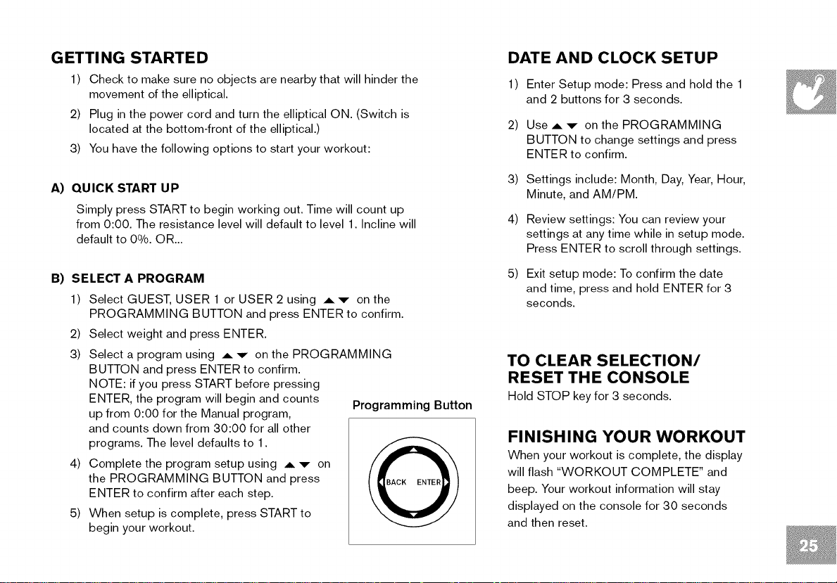
GETTI NG STARTED
1) Check to make sure no objects are nearby that will hinder the
movement of the elliptical.
2) Plug in the power cord and turn the elliptical ON. (Switch is
located at the bottom-front of the elliptical.)
3) You have the following options to start your workout:
A) QUICK START UP
Simply press START to begin working out. Time will count up
from 0:00. The resistance level will default to level 1. Incline will
default to 0%. OR...
B) SELECT A PROGRAM
1) Select GUEST, USER 1 or USER 2 using A'v- on the
PROGRAMMING BUTTON and press ENTER to confirm.
2) Select weight and press ENTER.
3) Select a program using
BUTTON and press ENTER to confirm.
NOTE: if you press START before pressing
ENTER, the program will begin and counts
up from 0:00 for the Manual program,
and counts down from 30:00 for all other
programs. The level defaults to 1.
4) Complete the program setup using ,6, ,v- on
the PROGRAMMING BUTTON and press
ENTER to confirm after each step.
5) When setup is complete, press START to
begin your workout.
A v on the PROGRAMMING
Programming Button
DATE AND CLOCK SETUP
1) Enter Setup mode: Press and hold the 1
and 2 buttons for 3 seconds.
Use ,6, v on the PROGRAMMING
2)
BUTTON to change settings and press
ENTER to confirm.
3)
Settings include: Month, Day, Year, Hour,
Minute, and AM/PM.
4)
Review settings: You can review your
settings at any time while in setup mode.
Press ENTER to scroll through settings.
5)
Exit setup mode: To confirm the date
and time, press and hold ENTER for 3
seconds.
TO CLEAR SELECTION/
RESET THE CONSOLE
Hold STOP key for 3 seconds.
FINISHING YOUR WORKOUT
When your workout is complete, the display
will flash "WORKOUT COMPLETE" and
beep. Your workout information will stay
displayed on the console for 30 seconds
and then reset.
PROGRAM INFORMATION
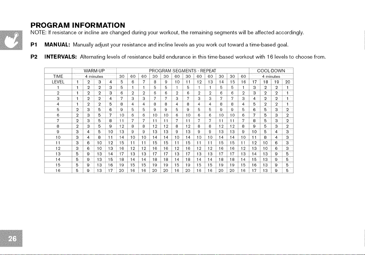
NOTE: If resistance or incline are changed during your workout, the remaining segments will be affected accordingly.
P1 MANUAL: Manually adjust your resistance and incline levels as you work out toward a time-based goal.
P2 INTERVALS: Alternating levels of resistance build endurance in this time-based workout with 16 levels to choose from.
WARM-UP PROGRAM SEGMENTS - REPEAT COOL-DOWN
TIME
LEVEL
1
2
3
4
5
6
7
8
9
10
11
12
13
14
15
16
4 minutes 30 60 60 30 30 60 30 60 60 30 30 60 4 minutes
1 2 3 4 5 6 7 8 9 10 11 12 13 14 15 16 17 18 19 20
1 2 2 3 5 1 1 5 5 1 5 1 1 5 5 1 3 2 2 1
1 2 2 3 6 2 2 6 6 2 6 2 2 6 6 2 3 2 2 1
1 2 2 4 7 3 3 7 7 3 7 3 3 7 7 3 4 2 2 1
1 2 2 5 8 4 4 8 8 4 8 4 4 8 8 4 5 2 2 1
2 3 5 6 9 5 5 9 9 5 9 5 5 9 9 5 6 5 3 2
2 3 5 7 10 6 6 10 10 6 10 6 6 10 10 6 7 5 3 2
2 3 5 8 11 7 7 11 11 7 11 7 7 11 11 7 8 5 3 2
2 3 5 9 12 8 8 12 12 8 12 8 8 12 12 8 9 5 3 2
3 4 5 10 13 9 9 13 13 9 13 9 9 13 13 9 10 5 4 3
3 4 8 11 14 10 10 14 14 10 14 10 10 14 14 10 11 8 4 3
3 6 10 12 15 11 11 15 15 11 15 11 11 15 15 11 12 10 6 3
3 6 10 13 16 12 12 16 16 12 16 12 12 16 16 12 13 10 6 3
5 9 13 14 17 13 13 17 17 13 17 13 13 17 17 13 14 13 9 5
5 9 13 15 18 14 14 18 18 14 18 14 14 18 18 14 15 13 9 5
5 9 13 16 19 15 15 19 19 15 19 15 15 19 19 15 16 13 9 5
5 9 13 17 20 16 16 20 20 16 20 16 16 20 20 16 17 13 9 5
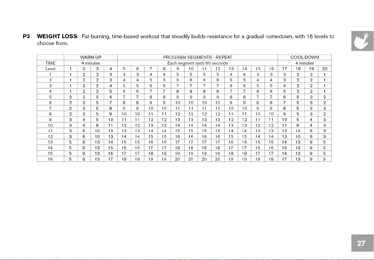
P3 WEIGHT LOSS: Fat-burning, time-based workout that steadily builds resistance for a gradual comedown, with 16 levels to
choose from.
TIME
Level
WARM-UP
4 minutes
1
2
3
4
5
6
7
8
9
10
II
12
13
14
15
16
1 2 2 3
1 2 2 3
1 2 2 4
1 2 2 5
2 3 5 6
2 3 5 ' 7
2 3 5 8
2 3 5 9
3 4 5 10
3 4 8 11
3 6 10 12
3 6 10 13
5 9 13 14
5 9 13 15
5 9 13 16
5 9 13 17
1 2 3 4
5 6 7 8 9 10 11 12 13 14 15 16
3 3 4 4 5 5 5 5 4 4 3 3
4 4 5 5 6 6 6 6 5 5 4 4
5 5 6 6 7 7 7 7 6 6 5 5
6 6 7 7 8 8 8 8 7 7 6 6
7 7 8 8 9 9 9 9 8 8 7 7
8 8 9 9 10 10 10 10 9 9 8 8
9 9 10 10 11 11 11 11 10 10 9 9
10 10 11 11 12 12 12 12 11 11 10 10
11 11 12 12 13 13 13 13 12 12 11 11
12 12 13 13 14 14 14 14 13 13 12 12
13 13 14 14 15 15 15 15 14 14 13 13
14 14 15 15 16 16 16 16 15 15 14 14
15 15 16 16 17 17 17 17 16 16 15 15
16 16 17 17 18 18 18 18 17 17 16 16
17 17 18 18 19 19 19 19 18 18 17 17
18 18 19 19 20 20 20 20 19 19 18 18
PROGRAM SEGMENTS - REPEAT
Each segment lasts 60 seconds
COOL-DOWN
4 minutes
17 18 19 20
3 2 2 1
3 2 2 1
4 2 2 1
5 2 2 1
6 5 3 2
7 5 3 2
8 5 3 2
9 5 3 2
10 5 4 3
11 8 4 3
12 10 6 3
13 10 6 3
14 13 9 5
15 13 9 5
16 13 9 5
17 13 9 5
PROGRAM INFORMATION
P4
CONSTANT WATTS: This workout automatically adjusts the resistance to keep you within a set Watts range and maintains
your desired level of exercise intensity.
1) Select Constant Watts program using ,6, v and press ENTER on the PROGRAMMING BUTTON.
2) Set time using ,6, ,v" and press ENTER.
3) Select desired watts using A v and press ENTER.
4) Press START to being the program.
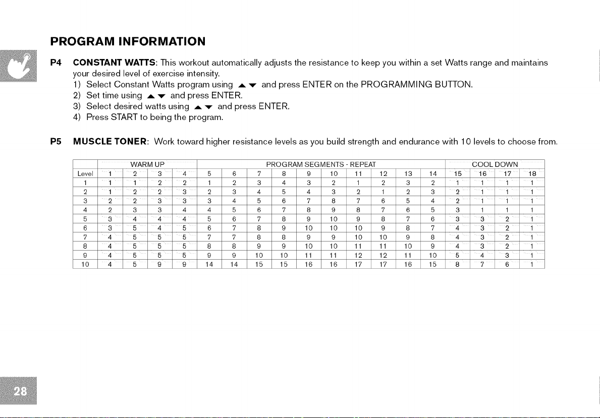
P5 MUSCLE TONER: Work toward higher resistance levels as you build strength and endurance with 10 levels to choose from.
WARM UP PROGRAM SEGMENTS - REPEAT COOL DOWN
Level 1 2 3 4 5 6 7 8 9 10 11 12 13 14 15 16 ' 17 18
1 1 ' 1 2 2 1 2 3 4 3 2 1 2 3 2 1 1 ' 1 ' 1
2 1 2 ' 2 3 2 3 4 5 4 3 2 1 2 3 2 ' 1 ' 1 ' 1
3 2 2 3 3 3 4 5 6 7 8 7 6 5 4 2 ' 1 ' 1 ' 1
4 2 3 3 4 4 5 6 7 8 9 8 7 6 5 3 1 1 1
5 3 4 4 4 5 6 7 8 9 10 9 8 7 6 3 3 2 ' 1
6 3 5 4 5 6 7 8 9 10 10 10 9 8 7 4 3 2 ' 1
7 4 5 5 5 7 7 8 8 9 9 10 10 9 8 4 3 2 ' 1
8 4 5 5 5 8 8 9 9 10 10 11 11 10 9 4 3 2 ' 1
9 4 5 5 5 9 9 10 10 11 11 12 12 11 10 5 4 3 ' 1
10 4 5 ' 9 9 14 14 15 15 16 16 17 17 16 15 8 ' 7 6 ' 1
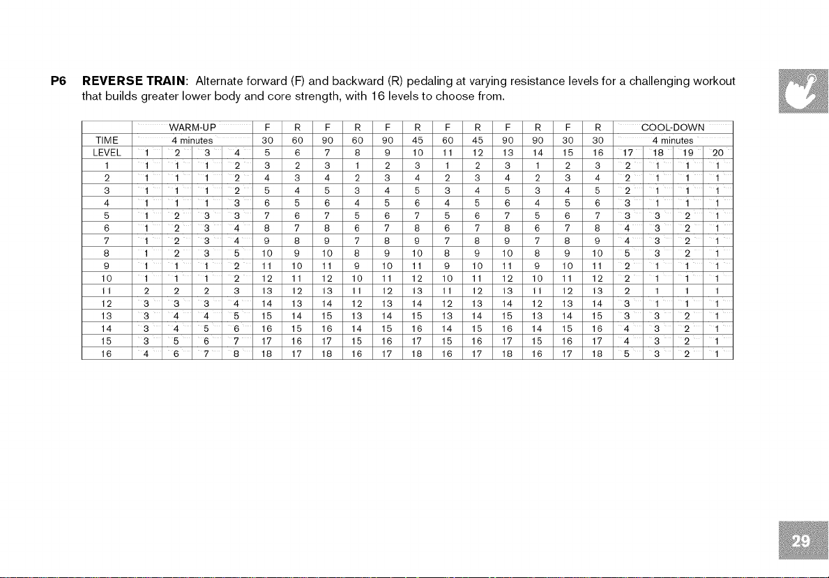
P6 REVERSE TRAIN: Alternate forward (F) and backward (R) pedaling at varying resistance levels for a challenging workout
that builds greater lower body and core strength, with 16 levels to choose from.
TIME 4 minutes 30
LEVEL 1 2 3 4 5
1
2
3
4
5
6
7
8
9
10
II
12
13
14
15
16
WARM-UP F
1 ' 1 ' 1 2 3
1 ' 1 ' 1 2 4
1 1 ' 1 2 5
1 1 ' 1 3 6
1 2 3 3 7
1 2 ' 3 4 8
1 2 3 4 9
1 2 3 5 10
1 1 ' 1 2 11
1 1 ' 1 2 12
2 2 2 3 13
3 3 3 4 14
3 4 4 5 15
3 4 5 6 16
3 5 6 7 17
4 6 ' 7 8 18
R F R F R F R F R F
60 90 60 90 45 60 45 90 90 30
6 7 8 9 10 11 12 13 14 15
2 3 1 2 3 1 2 3 1 2
3 4 2 3 4 2 3 4 2 3
4 5 3 4 5 3 4 5 3 4
5 6 4 5 6 4 5 6 4 5
6 7 5 6 7 5 6 7 5 6
7 8 6 7 8 6 7 8 6 7
8 9 7 8 9 7 8 9 7 8
9 10 8 9 10 8 9 10 8 9
10 11 9 10 11 9 10 11 9 10
11 12 10 11 12 10 11 12 10 11
12 13 11 12 13 11 12 13 II 12
13 14 12 13 14 12 13 14 12 13
14 15 13 14 15 13 14 15 13 14
15 16 14 15 16 14 15 16 14 15
16 17 15 16 17 15 16 17 15 16
17 18 16 17 18 16 17 18 16 17
R COOL-DOWN
30 4 minutes
16 17 18 19 20
3 2 1 1 1
4 2 1 1 1
5 2 1 1 1
6 3 1 1 1
7 3 3 2 ' 1
8 4 3 2 1
9 4 3 2 1
10 5 3 2 1
11 2 1 1 1
12 2 1 1 1
13 2 1 1 1
14 3 1 1 1
15 3 3 2 1
16 4 3 2 1
17 4 3 2 1
18 5 3 2 1
PROGRAM INFORMATION
P7
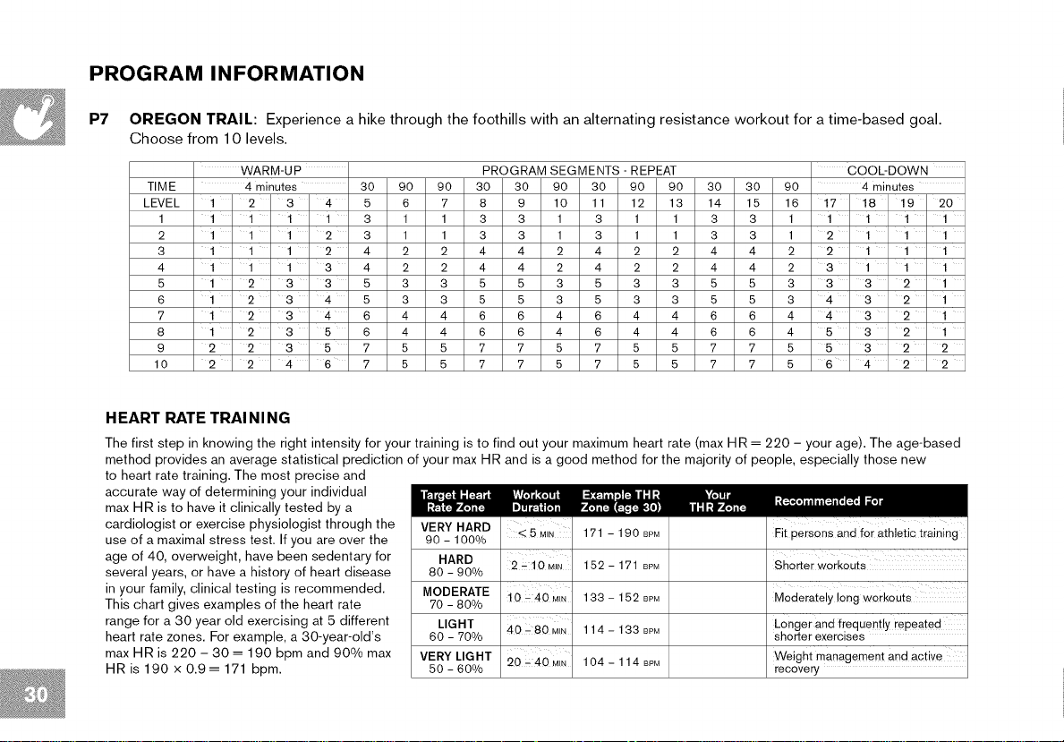
OREGON TRAIL: Experience a hike through the foothills with an alternating resistance workout for a time-based goal.
Choose from 10 levels.
TIME 4 minutes 30 90 90 30 30 90 30 90 90 30 30 90 4 minutes
LEVEL 1 2 3 4 5 6 7 8 9 10 11 12 13 14 15 16 17 18 19 20
1 1 ' 1 ' 1 1 3 1 1 3 3 1 3 1 1 3 3 1 1 1 1 1
2 1 ' 1 ' 1 2 3 1 1 3 3 1 3 1 1 3 3 1 2 1 1 1
3 1 ' 1 ' 1 2 4 2 2 4 4 2 4 2 2 4 4 2 2 1 1 1
4 1 1 ' 1 3 4 2 2 4 4 2 4 2 2 4 4 2 3 1 1 1
5 1 2 3 3 5 3 3 5 5 3 5 3 3 5 5 3 3 3 2 ' 1
6 1 2 ' 3 4 5 3 3 5 5 3 5 3 3 5 5 3 4 3 2 1
7 1 2 ' 3 4 6 4 4 6 6 4 6 4 4 6 6 4 4 3 2 1
8 1 2 3 5 6 4 4 6 6 4 6 4 4 6 6 4 5 3 2 1
9 2 2 3 5 7 5 5 7 7 5 7 5 5 7 7 5 5 3 2 2
10 2 2 4 6 7 5 5 7 7 5 7 5 5 7 7 5 6 4 2 2
WARM-UP PROGRAM SEGMENTS - REPEAT COOL-DOWN
HEART RATE TRAI NI NG
The first step in knowing the right intensity for your training is to find out your maximum heart rate (max HR = 220 - your age). The age-based
method provides an average statistical prediction of your max HR and is a good method for the majority of people, especially those new
to heart rate training. The most precise and
accurate way of determining your individual
max HR is to have it clinically tested by a
cardiologist or exercise physiologist through the
use of a maximal stress test. If you are over the
age of 40, overweight, have been sedentary for
several years, or have a history of heart disease
in your family, clinical testing is recommended.
This chart gives examples of the heart rate
range for a 30 year old exercising at 5 different
heart rate zones. For example, a 30-year-old's
max HR is 220 - 30 = 190 bpm and 900/0 max
HR is 190 x 0.9= 171 bpm.
VERY HARD 171 - 190 BPM
90 - 100%
HARD
80 - 90%
MODERATE tO L40 MIN 133 - 152 BPM
70 - 800/0
LIGHT 40- 80 MIN 114- 133 BPM
60 - 70%
VERY LIGHT 20 _ 40 M,N 104- 114 BPM
50 - 60%
2 - 10 M_N 152 - 171 BPM
Fit persons and for athletic training
Shorter workouts
Moderately long workouts
Longer and frequently repeated
shorter exercises
Weight management and active
recovery
 Loading...