

Aerovent IM-977 User Manual

IM-977
August 2014
General Installation, Operation and Maintenance Instructions For Aerovent Products
Introduction
DO NOT INSTALL, USE OR OPERATE THIS EQUIPMENT UNTIL THIS MANUAL HAS BEEN READ AND UNDERSTOOD.
READ AND SAVE THESE INSTRUCTIONS FOR FUTURE USE.
The purpose of this manual is to aid in the proper installation and operation of fans supplied by Aerovent. These
instructions are intended to supplement good general practices and are not intended to cover detailed instruction
procedures because of the wide variety and types of fans manufactured by Aerovent.
It is the responsibility of the purchaser to assure that the installation and maintenance of this equipment is handled
by qualified personnel experienced in such work and equipment.
Contact your local representative should you need further information.
Shipment and Receiving
Prior to shipment, all fans have been thoroughly inspected and tested.
All equipment shipped from Aerovent is boxed or crated to fully comply with trucking requirements. Inspect all shipments carefully for damage. THE RECEIVER MUST NOTE ANY DAMAGE ON THE CARRIER’S BILL OF LADING AND
FILE A CLAIM IMMEDIATELY WITH THE FREIGHT COMPANY IN THE CASE OF ANY DAMAGE. Keep a record of
all equipment received including inspection details and date of receipt due to the possibility of partial shipments.
If you receive damaged goods, contact your sales or factory representative for repair or replacement service.
Handling
Handle your equipment with caution. Some fans are provided with lifting lugs or holes for easy handling. Others must
be handled using nylon straps which protect the fan’s coating and housing. Spreader bars should be used when
lifting large parts.
Fans should be lifted by using straps around the fan housing only. DO NOT LIFT FANS BY THE MOTOR, MOTOR
BASE, PROP OR FLANGES.
Roof ventilators should be lifted by using straps around the fan housing or base only. Spreader bars should also be
used to avoid damage to stack caps or hoods. DO NOT LIFT ROOF VENTILATORS BY THE STACK CAP OR HOOD.
On hooded units, disassemble the stack from hood when lifting. Upblast models may be lifted assembled.
Storage
If fans are stored for any length of time, they should be stored in a clean, dry location to prevent rust and corrosion. Outdoor storage is not recommended. When outdoor storage is necessary, fans should be protected from the
elements as completely as possible. Cover fan inlets and outlets and keep motors dry and clean.
For extended storage (more than 3 months) motor shafts and bearings should be rotated monthly. If stored longer
than 6 months, bearing grease in the motor and fan should be purged and replaced with compatible grease. Re-check
belts for proper tension. Storage records should be kept to assure proper maintenance. The factory can advise warranty centers to provide motor and bearing service if needed.
©2014 Aerovent
Installation
Roof ventilators should always be mounted to a flat,
level, solid and rigid structure. Particular caution should
be exercised when installing fans on metal buildings. Be
sure wall or roof is capable of supporting the fan(s).
Fans mounted on walls or roofs and not supported correctly will cause vibration that could cause damage or
injury.
Fans mounted off ground level should be rigidly mounted to a structural platform and be placed over or as
near as possible to a solid wall or column.
Support for suspended fans must be cross-braced for
live load support to prevent side sway.
Use guy wires to help secure roof units if excessively
windy conditions prevail.
1. CAUTION! This fan contains rotating parts and
requires electrical service. Appropriate safety precautions should be taken during installation, operation
and maintenance.
2. WARNING! Do not install or operate this fan in an
environment or atmosphere where combustible or
flammable materials, gases or fumes are present
unless it was specifically designed and manufactured for use in that environment. Explosion or fire
can result. Explosive, corrosive, high temperature, or
other extreme conditions may require special construction, inspection and maintenance. It is necessary to observe the fan manufacturer’s recommendations and limitations concerning the type of material to be handled by the fan and its application to
special conditions.
3. When the roof ventilator is designed to be mounted
on a curb, the curb should be securely installed
prior to fan installation.
4. A damper, if used, should be securely mounted
within the curb or wall in a manner which allows
free and unobstructed operation.
5. CAUTION: All electrical work must be done in accordance with local and/or national electrical codes as
applicable. If you are unfamiliar with methods of
installing electrical wiring, secure the services of a
qualified electrician.
6. WARNING: This product must be grounded.
7. DANGER! Make sure power is turned off and locked
in the OFF position at the service entrance before
installing, wiring or servicing the fan.
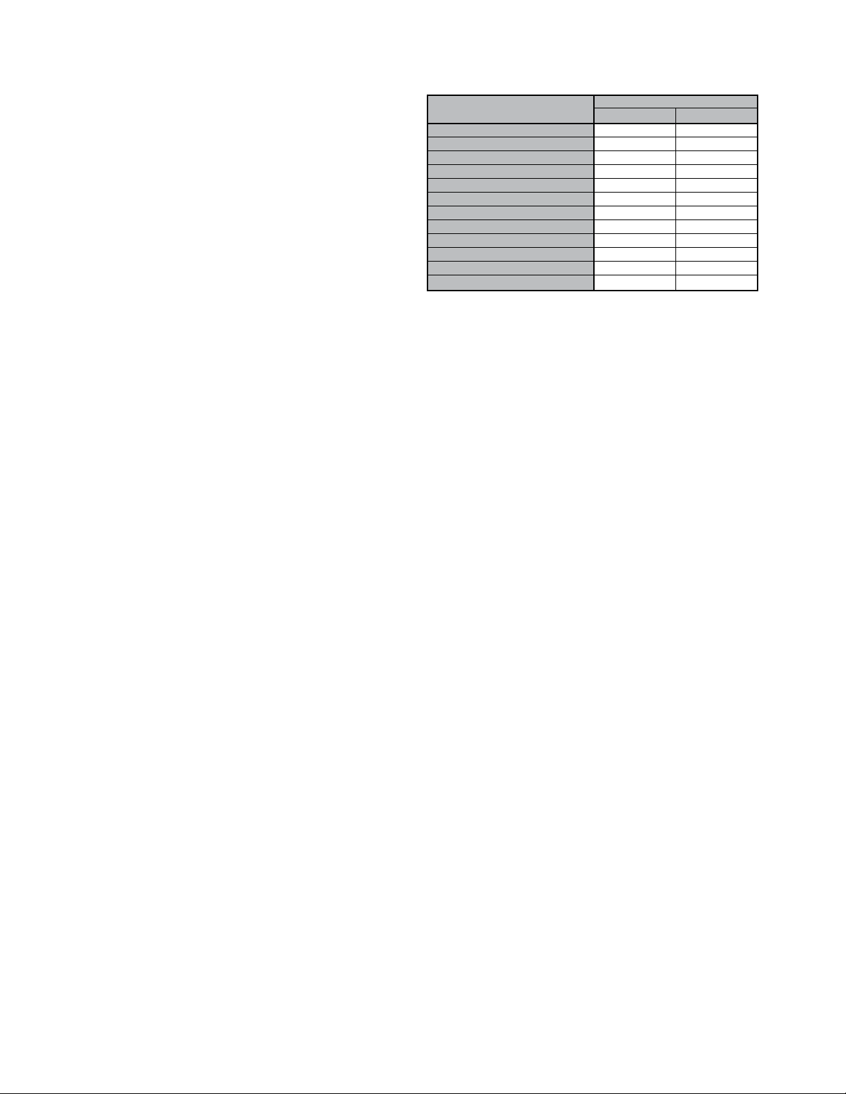
8. CAUTION! Before wiring the motor, check the supply
voltage against the motor nameplate voltage. High
or low voltage can damage the motor and void the
motor warranty. See Table 1.
Table 1. Utilization Voltages
SYSTEM VOLTAGE/ UTILIZATION VOLTAGE
UNIT NAMEPLATE MIN. MAX.
115/60/1 104 127
208-230/60/1 or 208-230/60/3 187 253
230/60/1 or 230/60/3 207 253
277/60/1 249 305
200/60/3 180 220
380/60/3 342 418
460/60/3 414 506
575/60/3 517 633
110/50/1 99 121
220/50/1 198 242
380-415/50/3 342 456
440/50/3 396 484
9. On three-phase units check and calculate phase
unbalance as follows:
% Voltage Unbalance = 100 x max. voltage deviation
from avg. voltage ÷ avg. voltage
How To Use The Formula:
With voltages of 220, 216 and 213
a. Avg. Voltage = 220 + 216 + 213 = 649 ÷ 3 = 216
b. Max. Voltage Deviation From Avg. Voltage =
220 – 216 = 4
c. % Voltage Unbalance = 100 x (4 ÷ 216) = 1.8%
Voltage unbalance should not exceed 2%.
10. WARNING! Be sure to keep all wiring clear of rotat-
ing or moving parts.
11. WARNING! Before starting the fan, turn the wheel
to assure it rotates freely. If needed, adjust the
wheel/shaft/bearing/motor position as required to
achieve necessary clearances.
12. On belt driven units, assure belts are tensioned and
aligned properly. See Maintenance section.
13. Check all setscrews and keys. Tighten as necessary
prior to fan startup.
14. On roof units, anchor the fan securely to the curb.
Anchoring through the vertical portion of the curb
cap flange is recommended. Use a minimum of four
lag bolts or other suitable fasteners.
15. As with most installations of rotating machinery, due
to the nature of their applications, most fans are
available with protective guards and/or other devices
for required operating safety. Before operating the
unit in any of its applications, determine requirements for any guards and/or devices needed for
protection against accidental contact with moving
parts or against injury to nearby personnel or equipment due to accidental rupture of fast moving
parts.
Check, Test and Start Procedure
1. Disconnect power to this unit before servicing the
unit. Make sure power is turned off and locked in the
OFF position.
2. Tighten all bolts and setscrews securely and, on belt
driven fans, check sheave alignment and belt tension.
Tighten belts if necessary. NOTE THAT ALL BOLTS,
SETSCREWS AND BELTS SHOULD BE CHECKED
AND TIGHTENED AFTER TWO DAYS OF INITIAL
OPERATION.
2 Aerovent IM-977
3. Clearance should be checked all around between
wheel or propeller tips and the housing before starting up. The wheel or propeller should not strike the
housing.
No initial lubrication is required. Motors and fan bear-
ings have been prelubricated by the motor manufacturer.
4. Apply power to the unit and check the rotation of the
wheel with the directional arrow on the unit.
WARNING: Especially check three-phase units for rotation.
For three-phase, rotation can be changed by interchanging any two of the three line leads. If the unit is checked
on temporary wiring, it should be rechecked when permanently installed. Motor burn-out or tripped overload
protection devices are usually the result of wrong rotation.
5. Electrical Input Check: Perform check of fan ampere
draw and verify that motor nameplate amps are not
exceeded. Take account of the service factor range if
motor is nameplated above a 1.0 service factor.
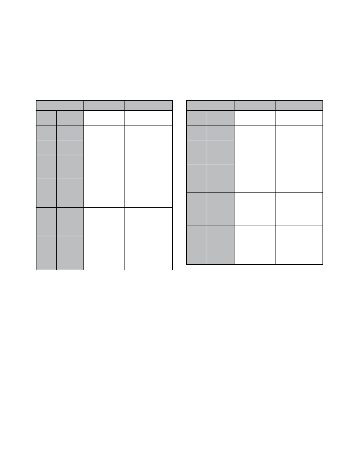
Table 2. Maximum Fan RPM (Belt Driven Units)
MODEL MOTOR HP
FAN RPM
1B, 2B, 3B 1/4 1680
12AFA 4B 1/3 1465
5B 1/2 1675
1B, 2B, 3B 1/4 1470
14AFA 4B 1/3 1620
5B 1/2 1850
1B, 2B 1/4 905
18AFA 3B 1/3 995
4B 1/2 1140
1B, 2B 1/4 570
3B 1/3 625
24AFA 4B 1/2 720
5B 3/4 820
6B 1 905
1B 1/3 440
2B 1/2 500
3B 3/4 575
30AFA
4B 1 630
5B 1
6B 2 795
1B 1/2 370
2B 3/4 425
3B 1 465
36AFA
4B 1
5B 2 585
6B 3 670
1B 1/2 320
2B 3/4 370
3B 1 405
40AFA 4B 1
5B 2 510
6B 3 585
7B 5 690
MAXIMUM
1
⁄2 725
1
⁄2 535
1
⁄2 465
6. Fan RPM Check: Fan RPM should be checked and
verified with a tachometer. Refer to Table 2 for maximum fan RPM values.
The fan should not need balancing, as it was balanced
at the factory to be within stringent vibration levels
before shipment. However, there are several things that
may cause vibration such as rough handling in shipment
and erection, weak foundations and alignments.
MODEL MOTOR HP
FAN RPM
1B, 2B, 3B 1/4 1420
14AWA 4B 1/3 1560
5B 1/2 1790
1B, 2B 1/4 900
18AWA 3B 1/3 990
4B 1/2 1135
1B, 2B 1/4 560
3B 1/3 615
24AWA 4B 1/2 705
5B 3/4 810
6B 1 890
1B 1/3 435
2B 1/2 500
3B 3/4 575
30AWA
4B 1 630
5B 1
6B 2 790
1B 1/2 365
2B 3/4 420
3B 1 460
36AWA 4B 1
5B 2 580
6B 3 660
7B 5 785
1B 1/2 315
2B 3/4 360
3B 1 395
4B 1
40AWA
5B 2 495
6B 3 570
7B 5 675
8B 7
MAXIMUM
1
⁄2 720
1
⁄2 525
1
⁄2 450
1
⁄2 765
Maintenance
1. Before performing any maintenance on the fan, be
sure power is turned off and locked in the OFF
position at the service entrance.
2. Ventilators should be carefully checked at least once
a year. For critical or rugged applications, a routine
check every two or three months is suggested.
3. All motors supplied with Aerovent ventilators carry a
one-year warranty from date of shipment. For repairs
within the warranty period, the motor must be taken
to the motor manufacturer’s authorized service
dealer. Contact your representative for additional
warranty details.
4. A periodic motor check should consist of spinning
the motor shaft with the power off to be sure the
motor turns freely and the bearings run smoothly.
The belt on belt driven units should be removed
from the motor sheave.
5. When removing or installing a belt, do not force the
belt over the sheave. Loosen the motor mount so
that the belt can be easily slipped over the
sheave.
Aerovent IM-977 3
6. The belt on belt driven units should be removed and
carefully checked for glazing, cracks, ply separation
or irregular wear. A small irregularity in the contact
surface of the belt will result in noisy operation. If
any of these defects are apparent, the belt should
be replaced. Check the sheaves also for chipping,
dents or rough surfaces which could damage the
belt.
7. The correct belt tension is important. Too tight a
belt will result in excess bearing pressure on the
motor bearings and shaft pillow blocks and may
also overload the motor. Too loose a belt will result
in slippage which will quickly “burn” out belts. A
belt should feel “live” when thumped, approximately
1
⁄4" belt deflection (3 to 5 lb.) when subject to finger
pressure at midpoint between sheaves.
8. The belt alignment should also be checked to be
sure the belt is running perpendicularly to the rotating shafts. Motor and drive shafts must be parallel.
Improper alignment will result in excessive belt
wear.
 Loading...