

Aerovent IM-632 User Manual
IM-632
August 2014
General Installation, Operation and Maintenance Instructions For Aerovent Products
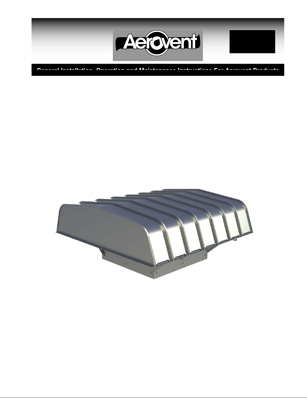
Hooded Propeller & Tubeaxial Roof Fans
Models: BSHB, BSHD
Aerovent Catalog 632 provides additional information on this equipment. This catalog
can be found at www.aerovent.com or by contacting your local Aerovent sales representative.
BSHB
©2014 Aerovent

Receiving, Unpacking & Inspection
When the equipment is received all items should be
carefully checked against the bill of lading to be sure all
crates and cartons have been received. Before accepting
delivery, carefully inspect each carton or crate for
visible shipping damage. If any damage is noticed, the
carrier should make the proper notation on the delivery
receipt acknowledging the damage. Make notations of
all damage on all copies of the bill of lading and have
all copies countersigned by the delivering carrier. The
carrier should also fill out a Carrier Inspection Report.
The factory Traffic Department should then be contacted.
File claim for damage with the carrier. Physical damage
to the unit after acceptance is not the responsibility of
Aerovent.
Unpack each carton or crate and verify that all required
parts and proper quantities of each item have been
received. Refer to drawings for part descriptions. Report
shortages or missing items to your local representative
to arrange for replacement parts.
Storage
If fans are stored for any length of time, they should
be stored in a clean, dry location to prevent rust and
corrosion. Outdoor storage is not recommended. When
outdoor storage is necessary, fans should be protected
from the elements as completely as possible. Cover the
fan inlet and outlet and keep motors dry and clean.
For extended storage (more than 3 months) motor shafts
and bearings should be rotated monthly. If stored longer
Due to availability of carriers and truck space, it is not
possible to guarantee that all items will be shipped
together. Verification of shipments must be limited to
only those items on the bill of lading.
The unit nameplate must be checked to make sure the
voltage agrees with the power supply available.
CAUTION: Sheet metal parts, screws, clips and simiar
items inherently have sharp edges, and it is necessary
that the installer and service personnel excercise
caution.
The installation of this equipment shall be in accordance
with the regulations of authorities having jurisdiction and
all applicable codes. This equipment is to be installed
by an experienced installation company and fully trained
personnel. The mechanical installation of the exhaust
ventilator consists of making final connections between
the unit and building services, duct connections.
than 6 months, bearing grease in motor and fan should
be purged and replaced with compatible grease. Belts
should be rechecked for proper tension. Storage records
should be kept to assure proper maintenance. The
factory can advise warranty centers to provide motor
and bearing service if needed.
Limitation of Warranties and Claims
Seller warrants to the original purchaser that the
goods sold hereunder shall be free from defects in
workmanship and material under normal use and service
(except in those cases where the materials are supplied
by the buyer) for a period of one year from the date of
original installation or eighteen (18) months from the date
of shipment, whichever occurs first. The liability of seller
under this warranty is limited to replacing, repairing, or
issuing credit (at cost, F.O.B. factory and at seller’s
discretion) for any part or parts which are returned by
buyer during such period provided that:
a. seller is notified in writing within ten (10) days
following discovery of such defects by buyer, or
within ten (10) days after such defects should
reasonably have been discovered, whichever is
less;
b. the defective unit is returned to seller, transportation
charges prepaid by buyer;
c. payment in full has been received by seller for said
products;
d. seller’s examination of such unit shall disclose to its
satisfaction that such defects have not been caused
by misuse, neglect, improper installation, repair,
alteration, act of God, or accident.
No warranty made hereunder shall extend to any
seller product whose serial number is altered, effaced
or removed. Seller makes no warranty, express or
implied, with respect to motors, switches, controls,
or other components of seller’s product, where such
components are warranted separately by their respective
manufacturers. THIS WARRANTY IS EXPRESSLY IN LIEU
OF ALL OTHER WARRANTIES, EXPRESS OR IMPLIED,
WHETHER STATUTORY OR OTHERWISE, INCLUDING
ANY IMPLIED WARRANTY OF MERCHANTABILITY OR
FITNESS FOR A PARTICULAR PURPOSE. In no event
shall seller be liable to buyer for indirect, incidental
collateral, or consequential damages of any kind.
(BUYER’S FAILURE TO PAY THE FULL AMOUNT DUE
WITHIN SIXTY (60) DAYS OF DATE OF INVOICE SHALL
OPERATE TO RELEASE SELLER FROM ANY AND ALL
LIABILITY OR OBLIGATION ARISING PURSUANT TO
ANY WARRANTY, EXPRESS OR IMPLIED, WHETHER
STATUTORY OR OTHERWISE, INCLUDING ANY IMPLIED
WARRANTY OR MERCHANTABILITY OR FITNESS FOR
A PARTICULAR PURPOSE, MADE IN CONNECTION
WITH ANY CONTRACT FORMED HEREUNDER. BUYER
AGREES THAT SUCH FAILURE TO PAY SHALL
CONSTITUTE A VOLUNTARY WAIVER OF ANY AND ALL
SUCH WARRANTIES ARISING PURSUANT TO SUCH
CONTACT.)
2 Aerovent IM-632
Electrical Connection
1. Connect supply wiring to a disconnect switch. Check
the wiring diagrams on the motor for connections.
2. The motor is factory set at the voltage marked on
the fan nameplate. Check the line voltage with the
nameplate voltage and wiring diagrams.
3. The main power wiring should be sized for the
ampacity shown on the dataplate. Size wires in
accordance with the ampacity tables in Article 310
of the National Electrical Code. If long wires are
required, it may be necessary to increase wire size
to prevent excessive voltage drop. Wires should be
sized for a maximum of 3% voltage drop.
CAUTION: Use copper conductors only.
CAUTION: Protect wiring from sharp edges. Leave
some slack in the line to prevent damage.
4. (Optional) Disconnect switches are not fused. The
power leads must be protected at the point of distribution in accordance with the fan dataplate.
Check, Test & Start Procedure
5. On fans without a thermal protector integral to the
motor (refer to unit or motor dataplate to determine
if protector is present) a separate overload device is
required. Refer to Sections 430-32 of the N.E.C. for
sizing.
6. All units must be electrically grounded in accordance
with local codes or, in the absence of local codes,
with the latest edition of the National Electrical
Code (ANSI/NFPA 70). A ground lug is provided as
standard in the unit terminal box. Size grounding
conductor in accordance with Table 250-95 of the
National Electrical Code. DO NOT use the ground lug
for connecting a neutral conductor.
7. Supply voltage to the power ventilator should not
vary by more than 10% of the value indicated on
the unit dataplate. Phase unbalance must not exceed
2%.
WARNING: Failure of motor due to operation on
improper line voltage or with excessive phase unbalance constitutes product abuse and may cause
severe damage to the unit’s electrical components.
WARNING
Electric shock hazard. Could cause severe injury or
death. Failure to bond the frame of this equipment
to the building electrical ground by use of the
grounding terminal provided or other acceptable
means may result in electrical shock. Disconnect
electric power before servicing equipment. Service
to be performed only by qualified personnel.
BEFORE START-UP: Disconnect power to this unit
before servicing the unit.
1. Check to verify that the propeller is free to rotate.
2. Verify that supply voltage on the line side of disconnect agrees with voltage on fan data plate and is
within the 10% utilization voltage.
3. Apply power to unit and check rotation of propeller
with the directional arrow on the unit.
WARNING: Rotation is critical. If allowed to operate
in the wrong direction, the motor will overload and
burn out.
WARNING: Check units for rotation. For three-phase,
rotation can be changed by interchanging any two of
the three line leads. If unit is checked on temporary
wiring, it should be rechecked when permanently
installed. Motor burn-out or tripped overload protection devices are usually the result of wrong rotation.
4. Electrical Input Check: Perform check of fan ampere
draw and verify that motor nameplate amps are not
exceeded. Take into account the service factor range
if motor is nameplated above a 1.0 service factor.
5. Fan RPM should be checked and verified with a
tachometer.
NOTE: The fan was balanced at the factory to be
within stringent vibration levels before shipment.
However, there are several things that may cause
vibration, such as rough handling in shipment and
installation, weak foundations and alignments.
Aerovent IM-632 3
 Loading...