

Aerovent IM-500 User Manual
®
IM-500
August 2013
General Installation, Operation and Maintenance Instructions For Aerovent Products
Direct Fired Air Make-Up Unit
Table of Contents
Unit Information .......................................................................... 1
Special Precautions ....................................................................... 2
Installation Codes ...................................................................2 - 3
Unit Location Restrictions ......................................................... 3
Sound and Vibration Information ............................................ 3
Installation Information ........................................................ 3 - 5
Electrical Installation ................................................................... 5
Gas Piping Installation .......................................................... 5 - 7
Operating Instructions and Parts ......................................7 - 12
Start-Up Procedure ............................................................12 - 14
Sequence of Operation .....................................................14 - 15
Circuit Analyzer/Troubleshooting ..................................15 - 16
Maintenance Recommendations .....................................16 - 18
Terms & Conditions/Warranty .......................................19 - 21
Start-Up Report ..................................................................22 - 24
FOR YOUR SAFETY
If you smell gas:
1. Open windows.
2. Do not touch electrical switches.
3. Extinguishanyopename.
4. Immediately call you gas supplier
WARNING: Improper installation, adjustment,
alteration, service or maintenance can cause
property damage, injury or death. Read the
installation, operating and maintenance instructions thoroughly before installing or
servicing this equipment.
Gas-red appliances are not designed for use in atmospheres containing ammable vapors or duct, or atmo-
spheres containing chlorinated or halogenated chlorinated or halogenated hydrocarbons.
Recirculation of room air may be hazardous in the
presence of: a) ammable solids, liquids and gases; b)
explosive materials (ie., grain dust, coal dust, etc.); and
c) substances that may become toxic when exposed to
heat.
An electrical disconnect must be installed having adequate ampacity (see marking on the heater for voltage
and ampacity), if the unit was not provided with one.
This disconnect shall be installed in accordance with
Article 430 of the National Electrical Code, ANSI/
NFPA 70.
This manual is the property of the owner. Please be
sure to leave it with them when the installation and
start-up of this equipment has been completed.
As Aerovent has a continuous product improvement
program, we reserve the right to change designs and
specications without notice.
FOR YOUR SAFETY
The use and storage of gasoline or other ammable vapors and liquids in open containers in the
vicinity of this appliance is hazardous.
AeroventRegionalOfce
800 S. High St.
Covington, OH 45318
(937) 473-3788
©2013 Aerovent
Aerovent Headquarters
5959 Trenton Lane
Minneapolis, MN 55442
(763) 551-7500
Recirculating Units
WARNING
On heaters which recirculate air, outside ventilation air
must be provided in accordance with the information
shown on the heater nameplate.
Building Relief
Adequate building relief MUST be provided so as not to
overpressureize the building when the heating system is
operating at its rated capacity. It should be noted that this
can be accomplished by taking into account, through standard engineering methods, the structure’s designed infiltration rate; by providing properly sized relief openings; or by
interlocking a powered exhaust system; or by a combination
of these methods.
Control Wiring
Entry for control wiring should be ran into the control
room provided. Please consult unit drawing and locate the
control room on that drawing.
REFER TO THE HEATER RATING PLATE FOR
DETERMINING THE MINIMUM GAS SUPPLY
PRESSURE FOR OBTAINING THE MAXIMUM
GAS CAPACITY FOR WHICH THIS HEATER IS
SPECIFIED.
Ventilation Air
Excessive recirculation or insufficient ventilation air, which
results in inadequate dilution of the combustion products
generated by the heater, may create hazardous concentrations of carbon monoxide, nitrogen oxide, and other com-
bustion products in the heated space.
Fossil Fuel Powered Equipment
If gas fork trucks or other fossil fuel powered equipment
are utilized in the conditioned area, additional ventilation
requirements for the factility must be addressed separately.
Applications
If there is any doubt in the application of this heater, consult the manufacturer.
Ventilation Air
All ventilation air to this heater MUST be ducted directly
from the outdoors.
Interlocks
If failure or malfunction of this heater creates a hazard to
other fuel burning equipment in the building (e.g. when the
heater is providing make-up air to a boiler room), the unit is
to be interlocked to open inlet air dampers or other devices.
Inlet Ducts
When inlet ducts are installed, the heater MUST exchange
the air inside the duct a minimum of 4X prior to an ignition
attempt. Please consult the manufacturer for instructions.
Insulated Units
It is NOT recommended that a recirculation unit be
installed in a building that is NOT insulated where the outside air temperature falls below 32
o
F.
2 Aerovent IM-500

Special Precautions
THE INSTALLATION AND MAINTENANCE
INSTRUCTIONS IN THIS MANUAL MUST BE
FOLLOWED TO PROVIDE SAFE, EFFICIENT AND
TROUBLE FREE OPERATION. IN ADDITION,
PARTICULAR CARE MUST BE EXERCISED
REGARDING THE SPECIAL PRECAUTIONS LISTED
BELOW. FAILURE TO PROPERLY ADDRESS THESE
CRITICAL AREAS COULD RESULT IN PROPERTY
DAMAGE OR LOSS, PERSONAL INJURY OR
DEATH.
1. In Canada, only 100% outside air unit may be installed.
They must be solely for replacing exhausted inside air
with heated air.
2. Unit must be installed such that no source of flam-
mable vapor, gases or dust is located within 20 feet
horizontally of the unit, unless that source is separated
from the unit by an enclosure of fire and vapor resistive materials.
3. Disconnect all power before making wiring connections to prevent electrical shock and equipment damage. All units must be wired in strict accordance with
the wiring diagram furnished and the NEC.
4. Turn off all gas before installing equipment.
5. Gas pressure to the unit controls must never exceed
the gas supply pressure on the data sheet. The unit and
its individual shutoff valve must be disconnected from
the gas supply during any pressure testing of gas supply piping system at pressures greater than the supply
pressure shown on the unit’s data sheet. (Maximum
pressure to the unit shall never exceed 5 psig.)
6. Check the gas supply pressure at the pressure gauge
upstream from the pressure regulator. A pressure
regulator, which will satisfactorily limit the gas supply
pressure, must be installed with each heater. Purging
air from gas lines and piping must be performed as
described in ANSI Z223.1, latest edition, “National
Fuel Gas Code” (or CAN/CGA-B149 codes in
Canada). STRAINERS BETWEEN THE SUPPLY
LINE AND AIR MAKE-UP UNIT ARE HIGHLY
RECOMMENDED.
7. Check damper operation to insure damper blades
travel to their full open position and that the damper
end switch is functioning properly.
8. To prevent unit or building structural damage, do not
operate unit where combustion air may be exposed to
chlorinated, halogenated or acid vapor laden air.
9. Minimum clearances to combustibles must be maintained. The minimum clearances to be maintained are
6" from the top, ends and sides of the unit. Allow a 36"
minimum clearance on the sides of the unit for servicing. Access doors are provided for servicing the gas
controls, electric components and drive adjustment.
The unit must be installed such that the surface tempera-
ture of any adjacent combustible material shall not exceed
o
F above an ambient temperature of 77o F.
90
10. Do not block or modify combustion or ventilation air
openings. Installation must conform to all local codes,
or in the absence of local codes, with National Fuel
Gas Code, ANSI Z223.1, latest edition (in Canada
install according to CAN/CGA-B149, Installation
Code for Gas Burning Appliances and Equipment” or
CAN/CGA-B149-2, “Installation Code for Propane
Burning Appliances and Equipment”).
11. Do not operate unit without exhaust fan or fans operating. Insure proper interlock with exhaust fan system.
Direct-fired units operate by heating air directly when
the air is passed over the burner flame. On initial burn-
er start-up, or on burner shut down some gas odor may
be detected. The presence of gas odors under these
temporary intermittent conditions does not indicate an
equipment problem, nor do they indicate a hazardous
or unsafe operating condition. Direct-fired equipment
is not recommended for installations that may be highly sensitive to temporary gas odors. If gas odors persist
after initial burner ignition, or for extended periods
after burner shut down, discontinue use of unit and
call a qualified service technician.
12. Installation in airplane hangars must be in accordance
with the Standard for Aircraft Hangars, ANSI/NFPA
409 and in public garages in accordance with the
Standard for Parking Structures, ANSI/NFPA
13. Use spreader bars when lifting equipment.
14. Consult piping, electrical and venting instructions
before installation. Keep all literature shipped with the
unit for future servicing. Leave all literature with the
owner.
15. If the failure or malfunction of this heater creates a
hazard to other fuel burning equipment in the building,
the unit must be interlocked to open inlet air dampers
or other such devices.
Installation & Manufacturing
Codes
Manufacturing:
A. The units as constructed conform to ANSI Air Make-
Up std. Z83.4, Z83.18, Z223.1, and HFPA54.
B. Wiring within the control panel meets and carries the
UL508 label and meets ANSI/INFPA #70-1987.
C. Piping within the unit meets ANSI Code Z223.1
National Fuel Gas Code.
D. Fan performance tested in accord with AMCA 210.
E. Fan Sound tested in accord with AMCA 310.
F. Insurance codes IRI and FM as requested.
G. Equipment components supplied carry the UL electri-
cal listings.
Installation codes governing unit installation by
contractors:
A. ANSI Z83.4, Z83.18, or Z223.1 (latest edition) as
applicable.
3 Aerovent IM-500

B. All installation of this equipment must be performed
by a qualified installation agency only defined in ANSI
Z223.1.
C. Electrical ANSI/INFPA #70-1987.
D. Aircraft hangar NFPA 409.
E. National Fuel Gas Code NFPA 54.
F. Installation of air conditioning and ventilating systems
NFPA 90A.
G. Parking Structures and Repair Garages NFPA 54.1.
Unit Location Restrictions and
Considerations
CAUTION
Units must not be installed where they may be exposed
to explosive or flammable atmospheres. In Canada, only
100% make-up air direct-fired units may be installed and
they must be applied solely for replacing exhausted inside
air with heated outside air.
1. Do not locate any gas-fired equipment where chlorinated or acid vapors are present in the combustion air
atmosphere.
2. When locating units, consider general space and heating requirements and availability of gas and electrical
supply.
3. Maintain minimum clearances to combustibles. The
minimum clearances are, 12" from the top, 12" from
the bottom, 12" from the sides, and 12" from the
ends.
4. Where necessary to provide working clearance beneath
the unit, the unit shall be installed at a suitable height
above the floor or otherwise adequately protected.
5. Allow 36" clearance on both sides of the unit for service access.
6. Do not modify or block combustion or ventilation
openings. Do not modify burner profile opening.
7. Do not install direct-fired units down stream from any
cooling system that utilizes refrigerants for cooling.
8. Be sure the structural support at the unit location is
adequate to support the weight of the unit.
9. Units require field support of the accessory filters and
inlet hood.
10. Some models may be split shipped to accommodate
maximum shipping widths. When assembling unit sec-
tions, make sure that the sections are properly caulked
and secured before operating the equipment.
11. Provide sufficient airflow across the burner. Refer to
unit data sheet for required airflow (cfm).
12. Units with motor horsepower below 7.5 hp are sup-
plied with an adjustable motor sheave. Units with 7.5
hp motors and above are supplied as standard with
fixed motor and blower drives. Units are supplied from
the factory with drives set for static pressure conditions
provided at the time of order. Check to make sure the
actual job site conditions match the conditions for
which the unit was ordered. If proper airflow cannot
be established with the drives furnished with the unit,
contact the factory for information on drive changes.
13. For economical installation and operation, locate each
unit close to the space it will serve, and close to the
utilities that will serve the unit.
Site Preparation
Before attempting to install the unit, be sure the site is
properly prepared.
1. Make sure there is enough clearance around the installation site to properly and safely rig and lift the equipment.
2. Watch for overhead power lines, or nearby utilities to
prevent accidental contact and damage.
3. Make sure the unit supports are adequate to support
the equipment.
Sound and Vibration Levels
All mechanical equipment generates some sound and vibration that may require attenuation. Locate the equipment
away from critical areas whenever possible. Frequently units
can be mounted above utility areas, corridors, restrooms,
and other non-critical areas. Generally a unit should be
located within 15 feet of a primary support beam. Smaller
deflections mean less vibration and noise transmission.
Field installed, factory supplied vibration isolators are available for suspended or rail/slab
mounted units. Internal, factory mounted blower and motor isolation may be ordered as an
option at the time the unit is ordered.
Installation
Duct Connections
To assure proper airflow from the discharge of the unit
follow these recommendations:
1. Be sure properly sized and designed discharge ducts
are installed. Velocities should be selected from 2,000
ft/min to no more than 3,000 ft/min for optimum effi-
ciency of operation.
2. Units should have a common discharge plenum of at
least three (3) hydraulic duct diameters.
3. As a general rule, all discharge ducts should have a
straight run of at least three (3) hydraulic duct diameters
before making turns in the ductwork.
Hydraulic Duct Diameter for Rectangular Ducts
= Dh = 4A/P
Hydraulic Duct Diameter for Circular Ducts
= Dh = D
Where:
Dh = Hydraulic Diameter
A = Cross Sectional Area of Rect. Duct
P = Perimeter of Rectangular Duct
D = Diameter of Round Cut
4 Aerovent IM-500

Return ducts should be designed in the same manner.
Where ductwork (or other enclosure) is installed to the inlet
or outlet of the unit in such a way as to cause a possible
gas trap and accumulation of a flammable mixture, a pre-
purge cycle shall be incorporated to provide not less than
4 complete air changes to the ductwork (or enclosure) by
volume prior to an ignition attempt.
Fire Dampers
Fire dampers installed in the inlet or outlet duct systems
shall be provided with electrical interlocks connected in the
safety limit control circuit so as to cause the heater to shut
down in case of fire in the ductwork, or heater. The electrical interlocks must be so arranged that the safety
circuit is electrically energized only when the fire damper is
in the wide open position.
4. Lift the unit into place and set the unit down evenly
on curb. Check to make sure unit is level and is firmly
seated on all corners of the curb.
5. If units are supplied with accessories for field mount-
ing, attach all accessories after the unit has been set in
place.
6. Make final unit connections to the electric power supply
and remote control circuits. Connect gas lines.
NOTE: Blow lines clean of shavings and sealant before
connecting to the unit pipe train (strainers are recom-
mended between gas supply lines and manifold pipe
train). Caulk all utility clearance holes and seams on the
unit after connections have been made.
If the unit is to be rail or slab mounted, use similar directions as noted in this installation section.
Utility Connections
Electric and control connections can be made from the side
or the bottom of the unit. The factory supplied gas connector is located on the side of the unit. The units normally are
supplied with factory mounted disconnects; holes can be
cut in the fixed side panels, or bottom of the unit for elec-
trical connections. Sealing of holes cut in the unit casing
for utility connections should be done with care to prevent
air and water leaks. All external wiring connections for outdoor units must be made with seal tight conduit. All wiring
must be in accordance with the National Electric Code.
Rigging Instructions
Each unit is supplied with four mounting and lifting brackets with 1” clearance holes for lifting hooks. When units
are supplied with factory mounted accessories,
“DO NOT use the accessory lifting eyes to support the load of the unit”. The accessory lifting eyes
should only be used to steady the load. The main load
should be placed on the unit’s lifting lugs.
The unit lifting lugs are supplied at the top of the
Aerovent units and provide maximum strength for lifting.
In order to lift the unit without damaging the
case, SPREADER BARS MUST BE USED!
A bead of caulking must be applied to the face of all
Slab Mounted Units
For ground level installation of unit, prepare a level concrete slab at least 4" thick and extending 6 inches beyond
the unit on an adequate footing and a generous bed of
gravel for proper drainage. The slab should include threaded anchor bolts to fit mounting holes and spaced according
to unit mounting dimension per unit drawings for securing
the unit in place. The anchor bolts should extend at least
2" above surface of the mounting slab to allow clearance
for mounting washers and nuts (bolts, mounting washers,
and nuts by others).
Other Notes:
Units are not always shipped in one piece. Some field
assembly is typically required. Hardware is included; sealant
and gaskets are not in all cases. FCBT units include a sealing tape for the flanges. ALL others units do not include
any sealants. Please contact your local representative for the
breakdown of the number of pieces prior to shipping.
Aerovent ships units in the most economical way.
Should it be desired to ship a larger or vertical unit in one
piece, please contact your representative immediately.
Inspect all seams after installation and recaulk as needed.
A small hole in the caulk or a seam not caulked will allow
water penetration.
flanges just prior to mounting and bolting. Then, bead
should be applied to outside seams after installation.
CAULKING IS NOT SUPPLIED WITH THE UNIT!
Roof Curb Mounted Units
Roof curbs should have a minimum height of 14". 24" high
roof curbs are available and raise the unit above roof water
Unit Installation
Follow the site preparation instructions for applicable
curb, rail, or slab mounted as noted in this section of the
manual. Check the nameplate of the unit before lifting to
insure that the model and serial number shown matches
and snow levels where required and are special ordered.
The curb can be installed with the roof in advance of the
unit. The curb is shipped knocked down with separate
instructions for its assembly, flashing, and sealing with the
roof.
that shown on the shipping papers. Check unit dimensions
and mounting holes prior to installation to ensure smooth
installation experience.
If the unit is mounted on a factory supplied curb:
1. Install roof curb using roof curb instructions (as noted
in this section of the manual).
2. Thoroughly clean and dry the top of the curb surface.
3. Attach a curb gasket around the top perimeter of the
Rail Mounted Units
To ensure longevity and integrity of the section joints, continuous rail mounting is preferred.
When rail mounting the units, use two continuous rails
for the length of the unit (in direction of airflow).
Where V-bank filters, dampers, and inlet
hoods are supplied additional supports are not
curb.
5 Aerovent IM-500

required, as structural design of accessories
will support these items. However, rails should
be extended to support cross members of the
accessories. Check the drawings in the front of
this manual.
Electrical Connections
CAUTION:
Disconnect power source before making wiring connections to prevent electrical shock and/or equipment damage.
WARNING:
ALL UNITS MUST BE WIRED STRICTLY IN
ACCORDANCE WITH THE WIRING DIAGRAM
FURNISHED WITH THE UNIT AND IN
ACCORDANCE WITH THE NATIONAL ELECTRIC
CODE ANSI/NFPA 70, LATEST EDITION. UNIT
MUST BE ELECTRICALLY GROUNDED IN
CONFORMANCE TO THIS CODE. ANY WIRING
DIFFERENT FROM WIRING DIAGRAM SUPPLIED
SHOULD BE CLEARED WITH FACTORY
ENGINEERING WITH WRITTEN APPROVAL FOR
VALIDATION OF UNIT WARRANTY.
Any damage to, or failure of this equipment caused by
incorrect wiring of the unit is not covered under the standard product warranty.
Electrical wiring diagrams are furnished with each unit
and can be found in the O&M manual, and a permanent
laminated diagram is located on the inside of the electric
control cabinet door. All units are supplied with a labeled
terminal strip for ease of wiring.
The power supply to the standard unit is be protected
with a lockable type fused disconnect switch. If a discon-
nect switch is not supplied with the unit, the field supplied
disconnect must have adequate ampacity and must be
installed in accordance with Article 430 of the National
Electrical Code, ANSI/NFPA 70.
External electrical service connections which must be
made include:
1. Main power supply to unit (120, 208, 240, 480, or 575
volt).
2. Remote control panel. Consult unit wiring diagram.
3. Separate 120V service for lighting and receptacles as
required.
4. Control wires connected to the remote temperature
selector must not be run close to or inside conduit with
power or ignition wires. Doing so may cause the unit
to function erratically or may destroy the amplifier. If
shielded wires are used, shield must be insulated and
grounded at the amplifier location only.
Supply voltage must be within 10 percent of the power rating with each phase balanced to within 2 percent of each
other. If not, advise the power company.
Before powering unit, make sure all multivoltage components (transformers, motors, etc.)
are wired in accordance with the correct supply
voltage.
The lighting circuits and unit receptacles
require the installation contractor to supply a
separate 120 volt single supply source to the
unit and be installed in accordance with Article
210 of the National Electrical Code ANSI/NFPA
70 - 1987.
Gas Piping Installation
CAUTION:
Gas pressure to main gas manifold must NEVER
EXCEED 5 psi.
The unit and its individual shutoff valve(s) must
be disconnected from the gas supply during any
pressure testing of the piping system. Before
assembling piping to unit manifold contractor
should be sure all rust, piping compound and
shavings have been removed from new piping.
(Strainers are recommended between unit pipe
train and supply piping.)
Always check the unit’s data form to determine the correct gas supply pressure for which the unit was designed.
1. Installation of piping must be in accordance with local
codes, and ANSI Z223.1, latest edition, “National Fuel
Gas Code”. (In Canada CAN/CGA-B149 Code).
2. Piping to units must conform to local and national
requirements for type and volume of gas handled,
and pressure drop allowed in the line. Refer to the air
make-up data form to determine the Btu capacity of
the unit and the type of gas the unit is designed to use.
Using this information refer to the ASHRAE Guide
Fundamentals Handbook, or other gas pipe sizing
guide to determine the correct supply pipe size. Allow
sufficient pipe size based on allowable pressure drop
in supply line. Where several units are served by the
same main, the total capacity of all the units served by
the main must be used. Avoid pipe sizes smaller than
1
/2".
3. After threading and reaming the ends, inspect piping
and remove loose dirt and chips.
4. Support piping so that no strains are imposed on the
unit controls.
5. Use two wrenches when connecting field piping to
units.
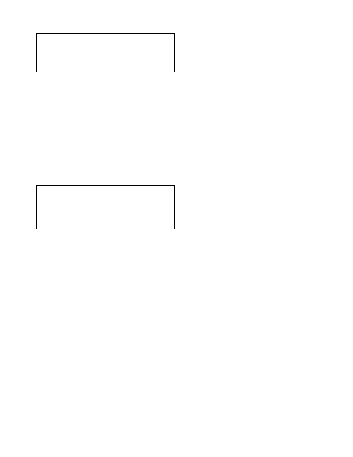
6. Provide a drip pocket before each unit and in the line
where low spots cannot be avoided.
7. Take-off to unit should come from top or side of main
to avoid trapping condensate.
8. Piping subject to wide temperature variations should
be insulated.
9. Pitch piping at least
run.
10. Compounds used on threaded joints of gas piping
must be resistant to action of liquefied petroleum
gases.
1
/4" per 15 feet of horizontal
6 Aerovent IM-500
11. Purge air from gas piping before lighting unit.
12. After air has been purged, check for gas leaks in the
piping system using a soap water solution.
13. Install a ground joint union and gas cock external of
the unit for easy servicing of controls.
14. Allow at least 5 feet of piping between any high pressure regulator and the unit control pipe train.
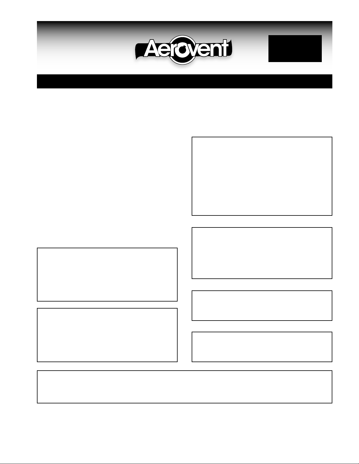
Gas Supply Pressure – 5 lbs. or less
The Aerovent air make-up unit is standardly furnished with
the Maxitrol modulating system. This device controls the
firing rate of the burner to maintain the desired operating
temperature.
It functions as a regulator and modulator which will not
allow the burner manifold pressure to exceed that which
produces the maximum firing rate, and also will reduce the
pressure below this value to modulate the burner throughout the normal 25 to 1 turn down ratio. The upstream
pressure supplied to the unit pipe train must not exceed 5
pounds. This is the maximum for suitable operation. The
minimum operating pressure will vary depending upon the
unit size and pipe train size. This pressure is marked on
the pressure gauge. As long as the gas pressure supplied to
the unit is maintained at some value between the minimum
as marked on the gauge and 5 pounds maximum, the air
make-up unit will perform at its rated capacity.
If the gas supply system is designed for a pressure
higher than 5 pounds, it is necessary to install an additional
regulator upstream of the connection to the unit. See following instructions for gas supply over 5 pounds.
The downstream pressure from the line regulator will
vary somewhat depending upon the firing rate of the air
make-up unit. Variations can also be caused by other gas
equipment connected to the distribution system. It is neces-
sary, therefore, to be sure that the setting of the supply line
regulator is such that the pressure supplied to the unit will
always be at least equal to the minimum and not exceeding
5 psi.
to handle the maximum capacity of the unit, and the type
of regulator selected to work at the maximum inlet pressure
and having a capability of maintaining the outlet pressure
at some value between 8 ounces and 5 pounds. As a rule,
the outlet pressure from the line pressure regulator may be
adjusted anywhere between 2 and 4 pounds. If the regulator was furnished by Aerovent, it has been sized according
to the information in the original order and shown on the
parts list. Regulators are sized according to capacity and
pressure and not according to pipe size; therefore, the size
of the pipe at the inlet to the air make-up unit may not be
the same as the pipe size of the regulator.
To be sure the supply line is properly sized, it is suggested that the representative of the local gas company be
consulted about pipe sizing. The line regulator should be
installed close to the air make-up unit. There should be no
elbows, couplings, valves, or fittings within at least ten pipe
diameters of the inlet and the discharge of the pressure
regulator. A shut-off cock should be placed upstream of
the regulator so that it can be removed for servicing if nec-
essary. It is a good idea, also, to install a pressure gauge on
the upstream side having a scale range sufficient to indicate
the supply line pressure.
It is very important to connect the regulator vent with
pipe or tubing extended to the outside with the end protected from the weather. Do not vent the regulator into the
air make-up unit or the duct system, or near the inlet to the
air make-up unit.
NOTE:
DO NOT VENT THE VENT VALVE AND PRESSURE
REGULATOR IN THE SAME VENT PIPE. SEPARATE
VENT LINES TO OUTSIDE ATMOSPHERE MUST
BE RUN FOR THE UNIT TO OPERATE PROPERLY.
COMBINING THE VENT LINES TO ATMOSPHERE
WILL CAUSE THE HIGH LIMIT GAS PRESSURE
CONTROL TO LOCK OUT THE FLAME SAFETY
SYSTEM AND SHUT DOWN THE UNIT.
NOTE:
Figure 1. Typical Gas Regulator
DO NOT VENT THE VENT VALVE AND PRESSURE
REGULATOR IN THE SAME VENT PIPE. SEPARATE
VENT LINES TO OUTSIDE ATMOSPHERE MUST
BE RUN FOR THE UNIT TO OPERATE PROPERLY.
COMBINING THE VENT LINES TO ATMOSPHERE
WILL CAUSE THE HIGH LIMIT GAS PRESSURE
CONTROL TO LOCK OUT THE FLAME SAFETY
SYSTEM AND SHUT DOWN THE UNIT.
NOTE:
A PRESSURE REGULATOR MAY BE REQUIRED TO
MEET THE STATE OR LOCAL CODE. CONSULT
YOUR STANDARDS.
Gas Supply Pressure – Over 5 lbs.
When the supply line pressure to an air make-up unit
exceeds 5 pounds or may at times fluctuate above 5 pounds,
it is necessary to install a line pressure regulator ahead of
the input to the air make-up unit. The size must be selected
7 Aerovent IM-500
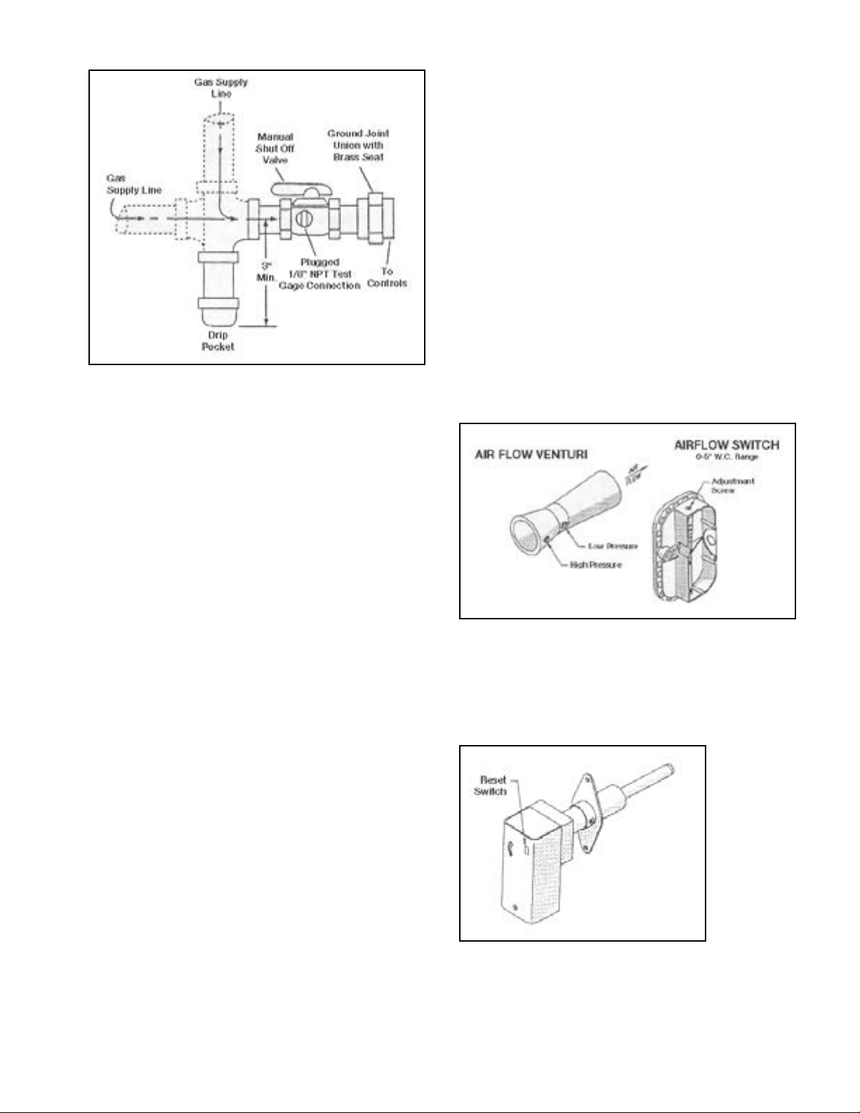
Figure 2. Piping Configuration
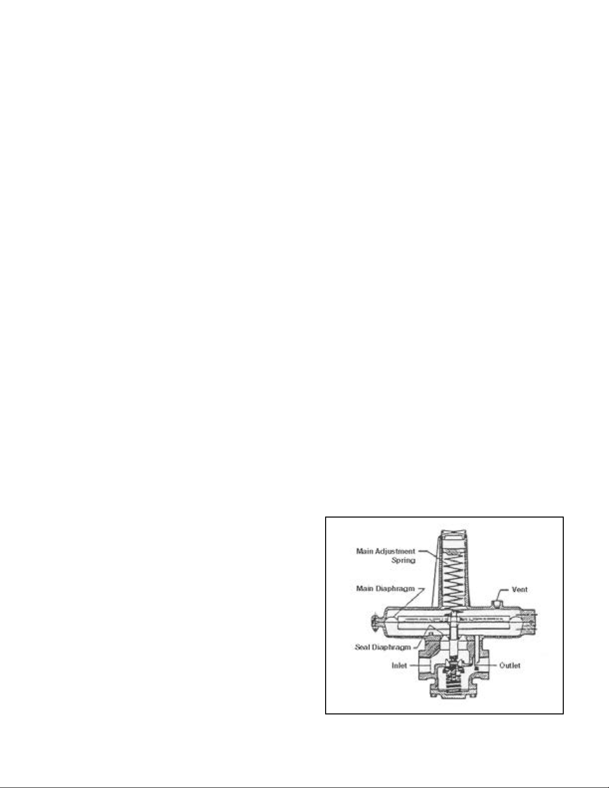
Airflow Proving Switch
(Aerovent Part #19240-01)
The airflow proving switch monitors the differential pressure across the venturi sensor located at the burner profile
plate to insure that sufficient airflow exists before allowing
the burner to operate. The airflow proving switch is located
in the gas controls cabinet and is electrically interlocked
with the flame safeguard control system. The air flow
venturi is located at the burner profile plate with pressure
taps leading from that location to the pressure switch. The
venturi amplifies the signal to the pressure sensing device
and minimizes nuisance shutdowns.
High Temperature Limit Control
(Aerovent Part #18756-01E)
The high temperature limit control shuts down the burner
if excessive discharge temperatures are experienced. The
limit control is located in the blower discharge air chamber.
The limit control is electrically interlocked with the flame
safeguard control relay.
Operation Instructions
PRIOR TO OPERATION
Although this unit has been assembled and test fired at the
factory, the following pre-operational procedures should
be performed to assure the unit has not been damaged or
misaligned during shipment. This will help assure proper
on-site operation.
1. Remove all shipping straps, braces, and tie-downs.
2. Check burner to insure proper location and if airflow
is moving across burner correctly. The burner may be
wrapped, if so remove wrapping. This is important if
unit was split for shipping convenience. Also check to
be sure sections were caulked when assembled.
3. Check blower and motor sheave alignment, as well as
belt tension.
4. Check bearings for alignment and tightness of mounting
bolts, bolts securing taper lock bushings to shaft, and
that locking collars are secure.
5. Check all electrical connections to insure wires are mak-
ing good contact and are secure in their terminals. Check
tightness of jumpers between terminals.
6. Check gas piping for leaks using a soap/water solution.
Figure 3.
Figure 4. High Temperature Limit
After these preliminary checks have been made, the unit
can be prepared for start-up.
Start-Up and Check Out
Each unit is supplied with a service manual which includes
a Field Start-Up Form. The Field Start-Up Form must
be followed and properly filled out and signed by
the installer. It then is to be mailed or faxed back to
Aerovent, 800 S. High St, Covington OH 45318. The
fax number is (937) 473-3793.
Before continuing with the start-up and checkout proce-
dure, it is important to familiarize yourself with
the safety controls furnished with the unit.
8 Aerovent IM-500
Flame Safeguard Control
(Aerovent Part #25941-01)
All units are equipped with a Honeywell RM7895C flame
safety relay. This relay senses if a pilot flame and main
burner flame have been established through the use of an
ultraviolet (UV) scanner. For more information about the
Honeywell flame relay, visit the Honeywell web site.
The flame safeguard relay has a built in component self
checking module, pre-purge timer, and an ignition timing
flame sensing circuit. The pre-purge timer allows purging of any residual gas or fumes in the unit before a try
for ignition. Pre-purge is approximately 10 seconds. After
pre-purge occurs, the spark ignition will start. If the pilot
flame is not proven within the time period allowed (10 to
25 seconds) the relay will go into lockout and it will have
to be manually reset before a try for re-ignition can occur.
This can be accomplished by pressing the reset button on
the remote station or at the unit thus preventing a trip to
the air make-up unit. If after several (2-3) tries the unit
won’t light off, have a maintenance man inspect the unit to
determine cause of relay lockout. Note: The power light
will blink; this is a normal operating condition.
Figure 5. Flame Relay
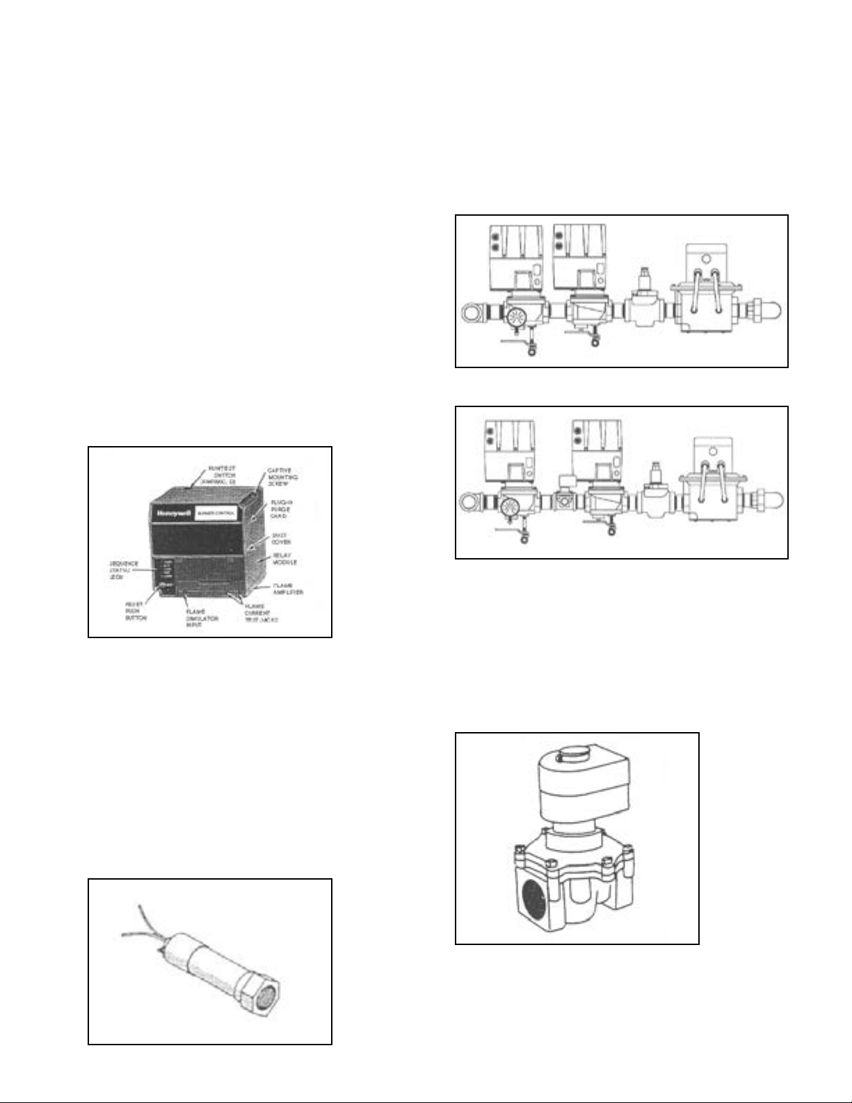
Gas Pipe Train Configuration
(Aerovent Part #2281-01E)
The type of manifold supplied with the unit varies depending on whether the unit was ordered with a FM or IRI
manifold. To determine which arrangement was supplied
with the unit, see the manifold descriptions noted on the
product specification and general description page in the
front of this manual.
Figure 7. FM Piping
Figure 8. IRI Piping
C7027 Ultra Violet Scanners
(Aerovent Part #2281-01E)
Units are equipped with a C7027A UV scanner. This device
is shipped removed from the flame sighting tube to prevent
damage during shipment. Unwrap the device and mount
on the sighting tube. The UV scanner is a ultra-violet light
sensing device. It takes advantage of the fact that a flame
will emit some of its light in the low frequency ultra violet
light range. The scanner uses an electronic eye to scan for
the presence of this ultra violet light. If flame is detected,
it sends this signal to the RM7895C flame relay.
Figure 6. UV Flame Detector (Purple Peeper)
Pilot Solenoid Gas Valve
(Aerovent Part #422-05E)
The pilot solenoid gas valve serves as a separate shut-off
valve for the pilot gas during normal operation and provides means for interrupted pilot and main flame supervision during normal operation of the unit.
Figure 9. Pilot Valve
9 Aerovent IM-500
 Loading...