

Aerovent IM-230 User Manual

IM-230
June 1997
General Installation, Operation and Maintenance Instructions For Aerovent Products
Belt Driven Plug Fans
Aerovent plug fans are designed for continuous duty in
air-moving systems, handling clean air where the fan
becomes an integral part of another system.
As a general rule, these fans are designed to be
installed in any position; however, reduced bearing life
may result in some vertical applications, which require
maximum static pressures and horsepowers.
The mounting panel, which is an integral part of the
assembly, permits easy installation to any well supported
plenum.
Upon receipt of equipment, inspect the fan and its
accessories for possible damage in shipment. Make
certain the wheel rotates without binding. Never lift the
plug fan by its motor, fan wheel or shaft. Lifting eyes
are provided for this purpose.
If the unit is not to be put in operation for a period
of time and is to be stored, the following precautions
should be observed:
1. Select a clean, dry location to prevent rust.
2. For outside storage, protect against the elements by
covering the entire fan.
3. Make certain bearings are filled with grease. (See
General Installation and Maintenance Manual IM-100
for lubrication procedure.)
4. Keep motors dry and clean.
5. Periodically inspect unit to see if conditions are present which could cause damage.
V-Belt Drive
Normally these units are shipped with motor and drives
in place, and it is only necessary to check for belt
alignment and proper tensioning. In cases where these
units are furnished less the motors and/or drives, the
mounting procedure is as follows:
1. Mount the motor on the adjustable base and secure
with the hardware provided. When located properly,
the motor end bell should be in a line with the end
of the motor base.
2. Remove the rust preventative compound on the end
of the fan shaft with a suitable solvent and wipe the
motor shaft clean.
3. Coat shaft with a light film of oil and mount sheaves
onto the shafts. Do not force the sheaves onto the
shafts as this may damage the fan and motor bearings. Do not apply any lubricant to the bushings,
threaded components, or setscrews. Be sure to wipe
©1997 Aerovent
off any excess lubricant in order to prevent the likelihood of any of the drive components from coming
loose during operation.
4. Install the belts. Belts should be worked carefully over
the grooves of each sheave until they are properly in
place. Belts should never be forced on with a screwdriver or similar tool as this may break the cords in
the belts. After the belts have been installed, adjust
the sheaves so that both shafts are at right angles to
the belts. Once proper alignment is assured, tighten
sheaves in place.
5. Take up slack by adjusting the motor base adjustment screws. Proper belt tension is important. If belts
are too tight, undue wear on fan and motor bearings
will result. Insufficient tension shortens belt life and
may cause vibration. Use drive manufacturer’s recommendations for correct belt tension.
6. IMPORTANT: BEFORE PUTTING THE UNIT INTO
CONTINUOUS OPERATION, INSTALL BELT GUARD.
7. After several days of operation, check belt tension
and sheave alignment.
Bearings
Before the unit is put in operation, tighten bearing collar setscrews and bearing anchor bolts. Rotate shaft to
check alignment.
All grease lubricated bearings are completely filled
with grease prior to shipment from the factory. This prevents the condensation of moisture in the pillow block
during shipment and before the unit is installed.
IMPORTANT: The bearings will discharge excess
grease through the seals for a short period of time after
start-up. Do not replace this initial discharge because
leakage will cease after the excess grease has been
purged from the bearings. Also, the purging of the
excess grease will cause the bearings to heat up but
the heat will dissipate after the purging.
Observation of the condition of the grease expelled
from the bearing at the time of relubrication is the best
guide as to whether the regreasing intervals and amount
of grease added should be altered. When regreasing,
use lubrication instructions for fan ball bearings as outlined in IM-100 which is included with the shipment.
Avoid mixing different types of grease. Bearings should
be flushed and refilled with fresh grease at approximately one-year intervals. DO NOT OVER LUBRICATE.
Maintenance
Regular and systematic inspection of all fan parts is the
key to good fan maintenance. Frequency of inspection is
determined by the severity of the application and local
conditions. Once a maintenance schedule is established,
it should be strictly followed. Regular fan maintenance
should include the following:
1. Check fan wheel for any build-up of foreign material
or excessive wear from abrasion. Both can cause
vibration which creates a serious safety hazard. Any
build-up of foreign material should be removed. If the
wheel shows excessive wear, replace it immediately.
Cleaning of the wheel should be accomplished, if
possible, without removing it from the shaft. If the
plenum is furnished with an access door, the wheel
can be cleaned through this opening. If no door is
supplied, then the inlet cone must be removed to
expose the wheel. If for some reason the wheel is
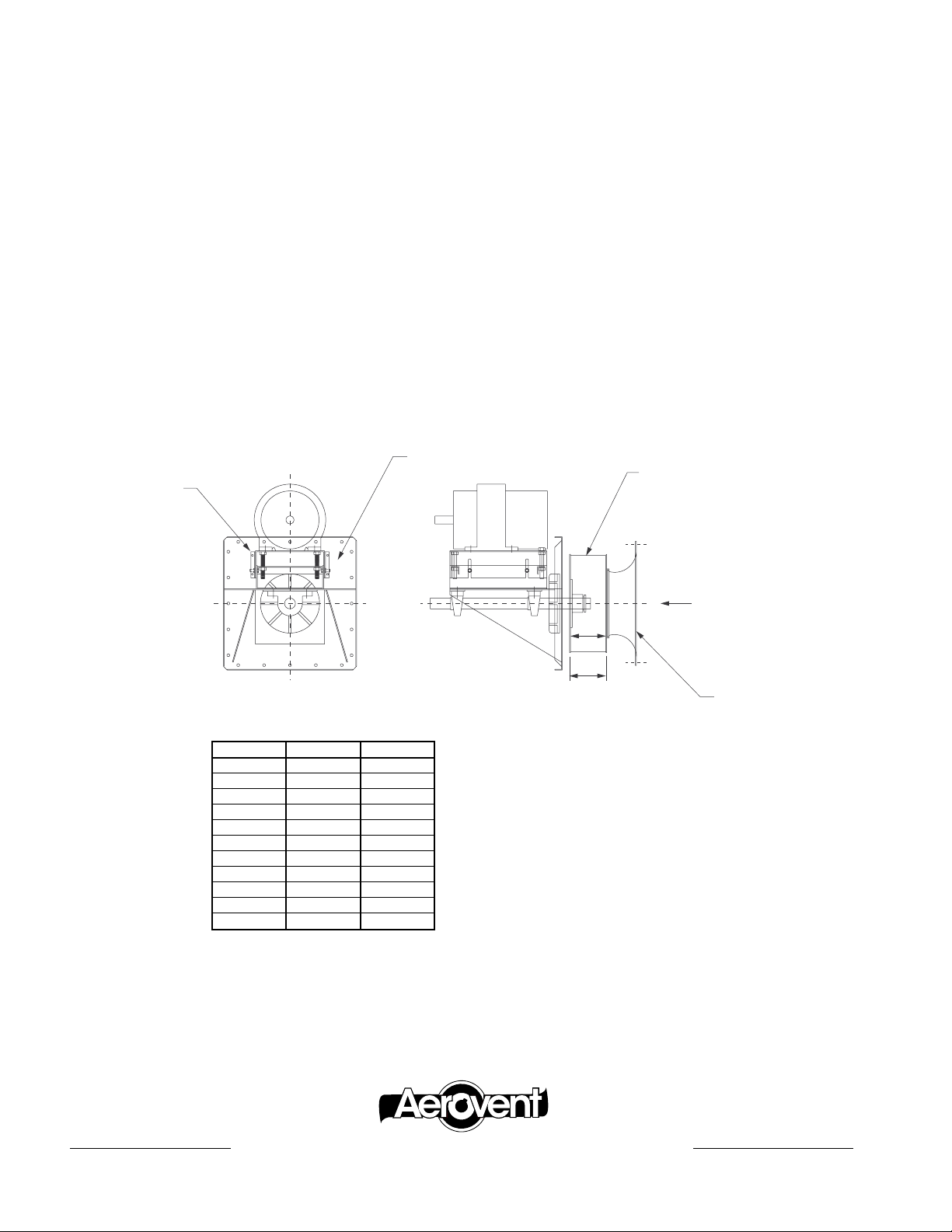
Mounting Panel
Adjustable
Motor Base
removed from the shaft, take note of the “A” dimension called out in the chart below. This dimension
must be held if the proper performance is to be
maintained.
2. V-BELT DRIVE: Check V-belt for proper alignment and
tension. (See General Installation and Mainten-ance
Manual IM-101.)
3. FAN BEARINGS: Lubricate the bearings as detailed in
the ball bearing lubrication instructions in the General
Installation and Maintenance Manual (IM-100).
4. SCREWS AND BOLTS: Check tightness of all screws
and bolts throughout the assembly
Wheel
SIZE A W
12 4
14 57⁄32 51⁄32
16 527⁄32 521⁄32
18 621⁄32 63⁄8
20 73⁄8 71⁄16
22 81⁄4 715⁄16
25 95⁄16 815⁄16
28 1017⁄32 101⁄16
32 1127⁄32 1111⁄32
35 1315⁄16 123⁄4
39 1427⁄32 143⁄16
5
⁄8 47⁄16
Airflow
A
W
Inlet Cone
“A” dimension (inlet cone to wheel
back plate) must be held. This
dimension is critical to fan performance. “A” dimension shown is
based on 100% wheel width and
must be adjusted if wheel furnished
is other than 100% full width.
®
AEROVENT | WWW.AEROVENT.COM
5959 Trenton Lane N | Minneapolis, MN 55442 | Phone: 763-551-7500 | Fax: 763-551-7501
 Loading...