

Aerovent IM-215 User Manual
®
IM-215
June 1997
General Installation, Operation and Maintenance Instructions For Aerovent Products
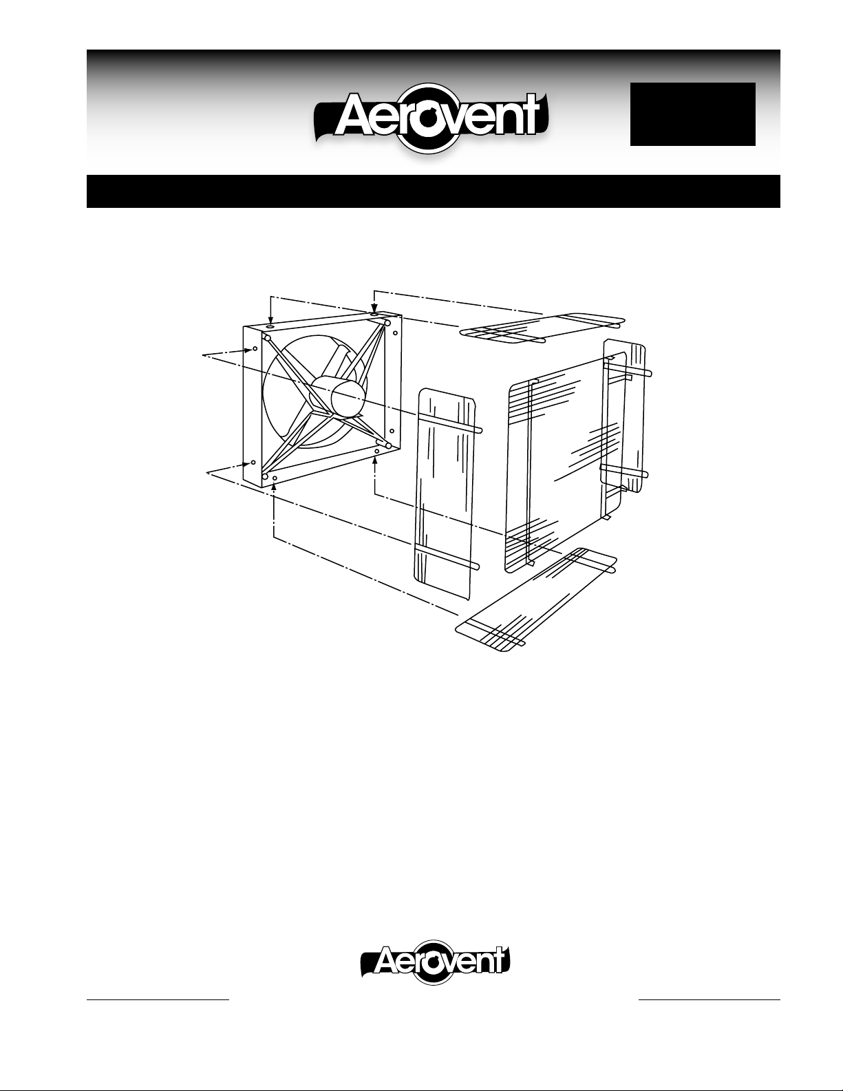
Rear Wire Guard (WWII) For Panel Fans
PARTS
(1) Rear Panel
(4) Side Panels
(16) or (24) 5∕16" x 1" Hex Head Capscrews
(16) or (24) Hex Head Locknuts
(32) or (48) 3∕8" I.D. Flat Washers
ASSEMBLY
1. Bolt three sides of guard to rear panel using 5∕16" capscrews,
nuts and flat washers.
2. Bolt partially assembled guard to panel fan using capscrews, nuts and flat washers.
3. Arrange for electrical hook-up to fan motor. Two methods
may be used:
a. Drill hole in fan panel and route wire or conduit
through opening.
– OR –
b. Bend or cut side panel wire guard and route wire or
conduit through opening.
4. Assemble fourth side to guard and panel, sliding along
conduit or wiring if routing through guard.
5. Securely tighten all locknuts.
®
AEROVENT | WWW.AEROVENT.COM
5959 Trenton Lane N | Minneapolis, MN 55442 | Phone: 763-551-7500 | Fax: 763-551-7501
©1997 Aerovent
 Loading...