

Aerovent IM-210 User Manual
IM-210
June 1997
General Installation, Operation and Maintenance Instructions For Aerovent Products
A-240 Aluminum Alloy & Dura Alloy
Propeller Assembly Instructions
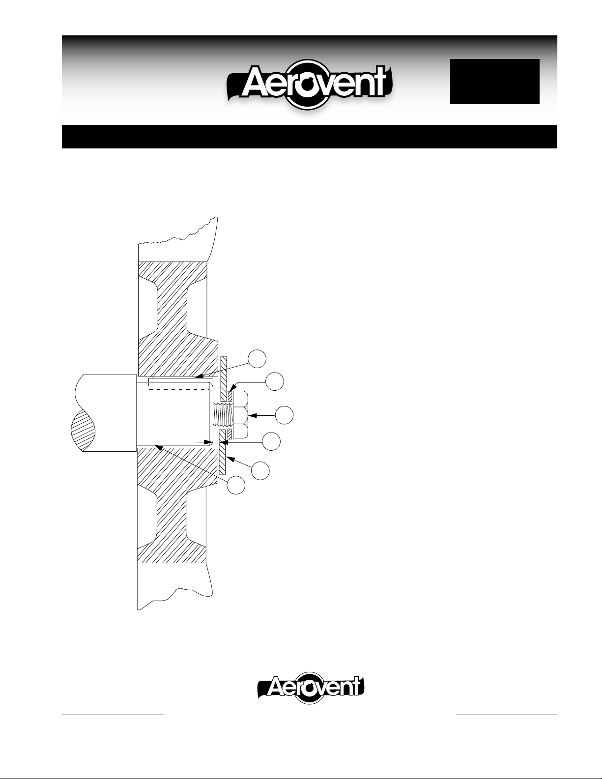
PARTS
A - Stainless Steel Shaft Key
B - Lock Washer (Stainless Steel)
C - Hex Head Bolt, R.H. Thread (Stainless Steel)
D - 1∕8" Minimum Gap — Between end of shaft and
washer
E - Flat Washer (10 GA. Stainless Steel)
F - Shaft Turndown — 1∕8" on shaft diameter through
3∕4"; 1∕4" on shaft diameter 1" and larger.
F
A
E
D
B
C
NOTE: Setscrews furnished in lieu of keyway on propellers
with 1∕2" bores.
ASSEMBLY
1. Insert key in shaft keyway.
2. Align keyway in propeller hub with key on shaft, and push
propeller onto shaft.
3. Place flat washer on shaft. Must have 1∕8" minimum gap.
4. Place lock washer on hex head. Bolt and tighten securely.
5. Rotate propeller by hand to check tip clearance of propeller blades to fan housing.
®
AEROVENT | WWW.AEROVENT.COM
5959 Trenton Lane N | Minneapolis, MN 55442 | Phone: 763-551-7500 | Fax: 763-551-7501
©2005 Aerovent
 Loading...