

Aerovent IM-201 User Manual

®
IM-201
August 2014
General Installation, Operation and Maintenance Instructions For Aerovent Products
AXICO® ANTI-STALL
(Direct Drive)
1.0 GENERAL DESCRIPTION
1.1 DEFINITIONS
A vaneaxial fan is an axial fan with a vane section
downstream of the rotor. The vane section converts the rotating component of the airflow into axial flow and pressure,
increasing the static pressure capability of the rotor.
An adjustable pitch rotor is one where the blade angle
can be changed, but only when the rotor is stationary.
A variable pitch rotor, also called controllable pitch,
is one where the blade angle can be changed while the fan is
running.
1.2 ARRANGEMENTS
Axial fans are available in two different configurations,
defined as follows:
Arrangement 4, Type 2 — The rotor is mounted
directly on the motor shaft, and the motor is upstream of the
rotor, with both rotor and motor enclosed in the fan tube.
Arrangement 4, Type 3 — The rotor is mounted
directly on the motor shaft, and the motor is upstream of the
rotor, but supported outside the fan tube.
Aerovent axial fans offer the following combinations
of these basic definitions, using the nomenclature shown:
Description AXICO
Vaneaxial Fan X
Adjustable Pitch FPDA
Variable Pitch:
Electric Control FPMC
Hand Crank Control FPMC
Pneumatic Control FPAC
Arrangement 4, Type 2 X
Arrangement 4, Type 3 X
1.3 APPLICATION
If the application requires that the inlet to the fan be
ducted, Arrangement 4 Type 3 cannot be used. All the other
arrangements are furnished with an inlet duct flange to which an
inlet duct or an inlet bell can be fastened.
Arrangement 4 Type 3 fans are ideally suited for plenum applications with a free inlet condition as this arrangement can permit the fan to be placed much closer to the coils
or filters upstream.
1.4 ACCESSORIES
Various accessories are available for AXICO fans.
a. Inlet bell and screen (standard on Arrangement 4 Type 3
fans)
b. Inlet cones
c. Vane section (standard on AXICO fans)
d. Discharge diffuser sections (two types)
e. Acoustic discharge diffuser sections
f. Flexible duct connections and band clamps
g. Gravity backdraft dampers
h. Vibration isolation
1.5 OPTIONS
AXICO fans may be furnished with various options to
meet job requirements:
a. Legs for floor mounting.
b. Brackets for vertical, horizontal, or angular mounting from
the floor or ceiling.
c. Electric operator or manual hand-wheel for adjustment of
AXICO FPMC when in operation, or quadrant and clamp
adjustment when the fan is turned off
d. AXICO fan operators and positioners located at other than
top dead center
1.6 NAMEPLATE NOMENCLATURE
The model number information on each fan nameplate is
explained on page 14.
2.0 INSTALLATION
2.1 RECEIVING/INSPECTION/STORAGE
Each Aerovent fan is shipped on a wooden pallet and
is covered with plastic for weather protection.
Carefully inspect the fan upon arrival for damage
incurred during shipment. Immediately report any damage to
both the factory and the carrier.
For short-term storage prior to installation, the fan
should remain covered with plastic wrap on the shipping pallet
and stored in a clean, dry location away from the elements. If
storage is to be for a period longer than 30 days, see page 15
for long-term storage instructions.
©2014 Aerovent
2.2 LIFTING
Aerovent fans should be lifted using slings. Note that
on AXICO fans the slings should be placed under the skids,
and spreader bars used as required. Under no circumstances
should the vane section be used for lifting.
2.3 MOUNTING
Depending on the type of fan support specified, the
fan can be floor mounted on legs, supported on a structural
frame or ceiling hung if clips or support brackets are included,
and again supported on the floor on a frame, or ceiling hung
if the fan is for vertical airflow.
2.3.1 Vibration Isolators
The fan is dynamically balanced to reduce vibration to
a low level. However, it is recommended that the fan be supported on vibration isolators. Isolators should be selected for
each installation in accordance with individual requirements.
The weight distribution between mounts is not equal
on Aerovent fans. Consult the factory for isolator selection
or mount loads. Isolators should be selected to support the
unequal load with equal deflection. A subbase can be used
to equally distribute the load to the isolators. Concrete inertia
pads are generally not required on Aerovent axial fans. When
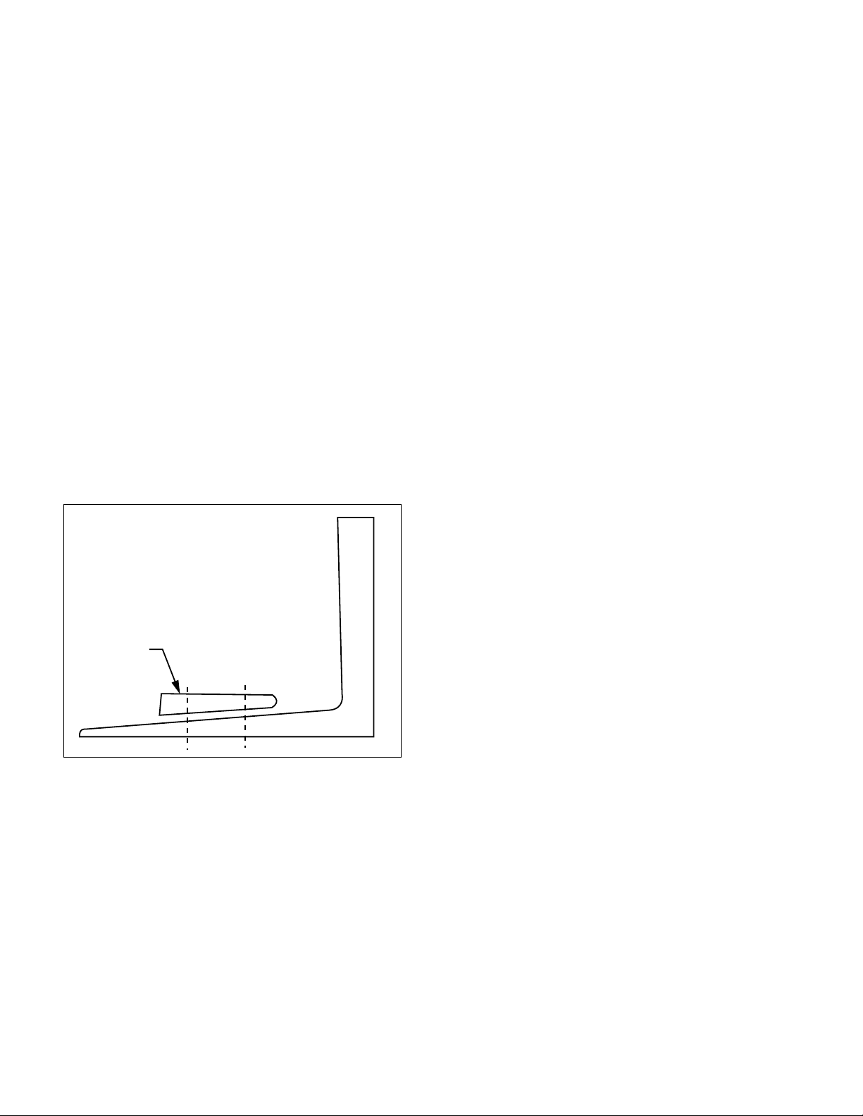
mounting isolators or tie-down bolts through the base frame
of an Arrangement 4 Type 3 fan, it is recommended that you
use a beveled washer between the base frame and the nut. See
Figure 1.
Figure 1.
Beveled
Washer
2.3.2 Fan Reactions
It is essential to minimize fan movement due to starting torque and air thrust force. These forces must be resisted
to maintain duct alignment and prevent damaging the flexible
connectors. Isolators must be selected with adequate stiffness
to resist these forces. Snubbers may be required in some installations to limit the fan movement.
2.4 DUCT CONNECTIONS
All fans should be closely aligned with the ductwork. A
flexible connection should be provided between the fan and
duct to prevent structure-borne noise from being transmitted to the ductwork. Use band clamps and seal with Borden’s
Arabol, or equal, to insure mechanical security and prevent
leakage on all flexible connections.
NOTE: Provide a 1-inch to 2-inch gap between the fan
and duct to allow for fan movement.
2.4.1 Diffuser and Cone Connection
On AXICO fans, the standard discharge is not intended to be directly connected to the fan vane section. Support
the diffuser independently of the fan and provide a flexible
connection between the fan and the diffuser. On all Aerovent
fans, inlet cones can be directly connected and they also
become part of the load to be isolated.
2.4.2 Inlet Bell Connection
The inlet bell may be mounted in a plenum wall with a
flexible connection between the outer edge of the bell and a
hole in the partition. Provide a 2-inch to 3-inch gap to allow
for fan movement.
The inlet bell may be installed protruding into the plenum where space is limited. A metal ring should be installed
between the inlet bell and the case flange and a flexible connection installed between the ring and the plenum wall.
2.5 ELECTRICAL
All wiring should conform to local electrical codes and
the job specification.
2.5.1 Power Connection
The motor leads terminate in the conduit box. The
leads are factory connected for the voltage specified for the
job. Motor leads for wye-delta and part-winding starts are
not connected. Rigid conduit should be run from the motor
starter to the fan with a short section of flexible conduit at the
conduit box to allow for fan movement.
Wire size and motor overloads should be sized in
accordance with the fan nameplate electrical data. The conduit
box is located on the outside of the case on all ducted, direct
driven fans. If the motor is outside the fan case, connection
will be made directly to the motor.
2.5.2 Motor Rotation
Check motor rotation by jogging the motor. The rotation should be clockwise when viewed from the inlet of the
fan. Reverse any two motor leads to change rotation.
NOTE: It is important that correct motor rotation be
established on ducted fans as the rotor will not be visible after
an inlet duct is installed.
2.5.3 Electrical Data
If the fan is a variable pitch AXICO fan, it is recommended that the fan not be run until the controls are operational. The fan should be started in accordance with Section
2.5.4 and the electrical data measured and compared to motor
nameplate ratings.
2.5.4 Final Check Before Putting
Fan Into Operation
1. Check for correct supply voltage and motor overloads.
2. Insure that all loose debris is removed from fan, fan
room, plenum and/or all ducts.
3. Check that motor bolts are tight and rotor is centered in
fan case with adequate blade tip clearance all- around. See
Section 6.6 for motor bolt torque data, and Section 6.7 for
minimum blade tip clearance.
4. Hand rotate and then bump the fan starter to check rotation.
5. Start the fan and verify that the vibration is acceptable.
If the fan is a variable pitch AXICO, make the following
additional checks.
6. Check that the air supply pressure is correct (60 to 100
psig).
2 Aerovent IM-201
7. Set controller at a low set point for minimum pitch (3 psig
branch pressure to the positioner) for direct acting.
8. Verify once again that the vibration is acceptable.
9. Increase the set point for maximum pitch and measure
motor current. Check that full load current does not
exceed motor nameplate data. Also verify that the vibration level at full pitch is acceptable.
10. Verify that blade pitch changes smoothly throughout
the full range as the controller set point is moved. If the
AXICO fan has an electric operator, follow the same procedure except of course varying the signal input circuit to
the Honeywell electric opener.
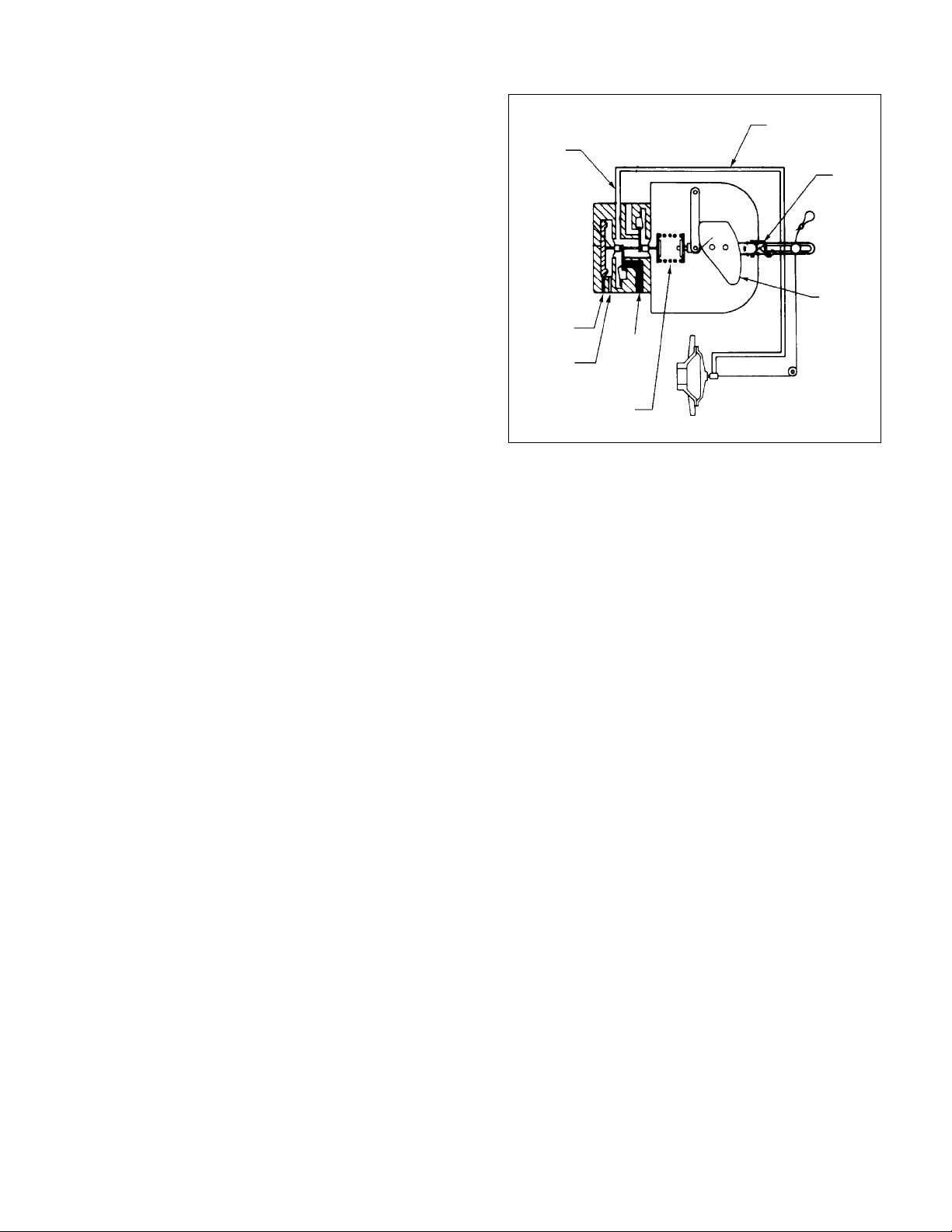
Figure 2. Schematic of Pilot Positioner and
Direct Acting FPAC Fan
Operating
Air To
Diaphragm
(Top Port)
Valve Air
Zero
Return
Spring
3.0 AXICO FAN BLADE ADJUSTMENT
3.1 FPAC FAN
The FPAC fan has a pneumatic diaphragm incorporated in the hub to operate the blade pitch changing mechanism. Air is supplied to the diaphragm through a rotary union
connected to a valve positioner mounted n the vane section.
The positioner is mechanically connected to the diaphragm by
a flexible cable.
3.1.1 Positioner — Function
The function of the positioner is to modulate the air
pressure to the diaphragm in response to the control pressure.
By means of the mechanical feedback it can sense the blade
pitch and thus satisfy the control set point. The positioner will
provide linear response to the control pressure.
The positioner is factory set to operate in the direct acting mode. This means that a decreasing control pressure will
cause a decrease in blade pitch and less airflow.
3.1.2 General Description of How It Works
The pilot positioner is a single acting, singe-stage,
force-balance type control device. Mounted on an AXICO
fan, and cable-connected to the rotor operating mechanism, it
uses an auxiliary air supply and a feedback cam controlled by
the cable to position the rotor mechanism in accordance with
the 3-15 psig air signal from the controller.
Figure 2 is a schematic diagram of this system.
Remember that the feedback spring maintains upward pressure on the positioner arm at all times, and this keeps the
cable in tension. Since the positioner is direct acting, a 3 psig
instrument gauge pressure results in 0 psig valve gauge pressure or minimum pitch position. When the instrument gauge
indicates 15 psig, this results in maximum valve pressure and
thus maximum pitch. The tendency of the fan blades is to go
to minimum pitch, so that, when the diaphragm pressure is
reduced, the spider will move towards the rotor, pulling the
positioner arm down and compressing the feedback spring.
3.1.3 Positioner Connections
There are three 1∕4" NPT ports on the positioner. The
top port is connected to the diaphragm on the fan rotor.
The middle port should be field connected to the controller
(branch line). The bottom port should be field connected to
main air supply. Supply air should be clean and dry instru-
ment air. Moisture or dirt in the supply air will cause
the pilot on the positioner to malfunction after repeated
exposure. The supply pressure to the positioner should be
regulated as required to achieve full pitch. The supply pressure
needed is a function of fan speed and size.
Controller
Input Signal
Air (Middle
Port)
Vent
Main Air
Supply
(Bottom
Feedback
Spring
Port)
Fan Rotor
Feedback
Cam
3.1.4 Positioner Calibration and Adjustment
The positioner is factory calibrated and no further
adjustment is normally required. The calibration can be easily checked and corrected if normal fan control cannot be
achieved. The positioner must be adjusted if replaced or the
cable is removed from the lever arm.
To adjust the positioner, proceed as follows:
1. With fan off, disconnect the air line on the positioner to
the fan rotor and connect this line to a
1
∕4" NPT pressure
regulator.
2. Check that the cable is in alignment with the hole where
it enters the stator vane core. If not, adjust the positioner
on the mounting bracket (not the pin in the slotted arm),
keeping the positioner horizontal with respect to the case.
3. Adjust the pressure regulator to supply full line pressure
to the fan diaphragm. Loosen the cable clamp on the
positioner arm and pull cable tight. Mark the cable where
it protrudes through the stator case. This is the maximum
pitch position. Reduce the pressure to the diaphragm to
zero and start the fan while maintaining tension on the
cable by pulling upward on the cable. The fan will now be
in the minimum pitch position.
Mark the cable again in the minimum pitch position. Turn
off the fan.
WARNING: Do not release cable tension while fan is in
operation. Wait until fan has come to a complete stop.
NOTE: The blades may not fully return to the minimum
pitch position unless fan is operating.
4. Adjust the pressure to the diaphragm to move the cable
midway between the two reference marks. Measure carefully and maintain this position. Remove the side cover
plate on the positioner. Grasp the positioner arm and move
it to align the line engraved on the cam with the centerline
of the cam roller (see Figure 2). Tighten the cable clamp.
NOTE: The positioner is now mechanically adjusted at
mid-range with the fan blade pitch mechanism at the mid
position.
Aerovent IM-201 3

5. Reconnect air line from the diaphragm to the positioner.
6. Proceed with the positioner calibration, as described
below:
a. Connect a 1∕4-NPT pressure regulator to the instrument
port to simulate a control pressure.
b. Turn on the supply air. Adjust the regulator to 9 psig
control pressure.
c. The mark on the cam should point to the center of the
cam follower. If not, turn spring adjusting nut to align
the mark.
d. Replace the cover plate and reconnect the control pres-
sure line to the middle port.
e. The positioner is now adjusted and calibrated to provide
linear blade pitch control from a 3 to 15 psig control
pressure.
NOTE: It is advised that a 0-30 psi pressure gauge of
known accuracy be used during the calibration procedure.
NOTE: In the event that a positioner has to be replaced
with a new part, the pin in the slotted arm on the new
part should be placed in the identical position as on the
old one. Specifically, the slot marking should match the
distance between the marks made on the cable in item 3
of the adjustment instructions above.
3.1.5 Air Consumption
The bleed rate of the positioner is zero. Under operating conditions, an FPAC fan will use a maximum of 0.25
SCFM of supply air.
3.2 FPMC FAN
The FPMC fan is a mechanical version of the AXICO
fan. Pitch control is achieved by a mechanical linkage connected to a thrust bearing in the hub cover. This arrangement
is available in three versions:
1. FPMC with electric operator mounted on the outside of
the vane section.
2. FPMC with a manual gear/jack mounted inside the core
of the vane section, and a handwheel mounted on the side
of the vane section to adjust pitch. This version can be
adjusted while the fan is running.
3. FPMC with the same linkage as on the motor-operated
version, but the input end of the linkage is clamped in one
position on a quadrant. This version cannot be adjusted
while the fan is running.
3.2.1 FPMC, Electric Motor Operator
The 120 VAC operator is used with FPMC fans. This
operator provides position proportion control of the AXICO
mechanical blade linkage. The operators are furnished with
end limit switches which have been factory set to match minimum and maximum pitch conditions required for each fan.
The motor will rotate the output shaft through an arc of 150°,
but the switches have been set to give the necessary linkage
stroke within this 150° arc. Operating time is 60 seconds for
the full 150°, so on an AXICO fan the time will be somewhat
shorter. The motor has a 135 ohm balancing slide wire which
must also be connected to the control relay. The motor is also
equipped with a 135 ohm feedback slide wire to permit an
output signal which can be used as the input signal to a second
relay which would control a parallel fan.
3.2.1.1 Control
Since fan pitch is being used to control duct system
static pressure in the majority of cases, a pressure sensing
transducer or slide wire bridge must be used in conjunction
with a balancing relay. This relay will operate a single pole
double throw switch to feed power of the correct polarity
to the operator motor to achieve CW or CCW rotation of
the output shaft. If the balancing slide wire is not connected,
the motor would run until the limit switch cuts power to the
motor in that circuit direction. Not until polarity is reversed
would the motor operate, and then it would go through full
stroke in the opposite direction until the second limit switch is
opened.
By connecting the balancing slide wire circuit back
to the balancing relay, the relay is now able to compare the
requirements of the duct sensor with the actual rotation of the
operator, and the comparison will make or break the SPDT
switch, changing operator rotational direction in a stepping
manner. Thus, the system becomes proportional.
3.2.1.2 Actuator Electrical Connection
All electric connections should be in strict accordance with the job specification and local electric codes. Refer
to the current manufacturer's owner's manual for a schematic
wiring diagram.
3.2.1.3 Actuator Replacement
The actuator is factory adjusted to provide the
full range of blade pitch movement. Should the actuator be
replaced, the limit switches must be adjusted to prevent the
motor from stalling at the maximum and minimum pitch positions.
To replace the actuator proceed as follows:
1. Remove the crankarm from the motor shaft without disturbing the ball joint and pushrod location.
2. Remove wiring and mark terminal locations.
3. Remove four mounting bolts and replace actuator with
new unit.
4. Remove four screws from the end cover and remove the
cover.
5. Connect 120 VAC power to the proper terminals, according to the owner's manual, to drive motor to mid-position
of shaft rotation as indicated by wiper arm location.
6. Move pitch control lever to mid-position and install crankarm on motor shaft.
7. Drive motor counterclockwise, according to the owner's
manual, to the maximum pitch position.
8. Adjust limit switch (LS1), according to the owner's manual, to open at this position.
9. Drive motor clockwise, according to the owner's manual,
to the minimum pitch position.
10. Adjust limit switch (LS2), according to the owner's manual, to open at this position.
CAUTION: Check that the limit switches are properly
adjusted and that the actuator motor does not stall at
either of the two extreme positions.
11. Reconnect wiring, according to the owner's manual, and
replace covers.
3.2.1.4 Actuator Linkage Adjustment
Should the linkage be removed during fan disassembly, it may be adjusted as follows:
1. Position the pitch control lever and actuator motor at
mid-position per Section 3.2.1.3.
2. Install crankarm in an upward vertical position on motor
shaft.
3. Install ball joint on crank arm at the minimum radius
from shaft, which will permit the wiper arm to operate
within the length of the slide wire. It must not run off at
either end.
4 Aerovent IM-201

4. Install push rod and tighten ball joint.
5. Adjust limit switches per Section 3.2.1.3.
3.2.1.5 Actuator Pitch Adjustment
The maximum and minimum blade pitch is mechanically
set in the rotor. The limit switches in the actuator can be reset
to reduce the range between these limits to provide different
maximum and minimum airflows. This may be done as follows:
1. Remove terminal box and/or end covers from actuator as
required.
2. Energize terminals, according to the owner's manual, with
120 VAC to drive the blades to minimum pitch.
3. Start the fan and energize the proper terminals, according to the owner's manual, to increase the pitch until the
desired maximum airflow is obtained.
4. Adjust limit switch (LS1), according to the owner's manual, to open at this position. This will stop the motor at
the new maximum pitch position.
5. Energize terminals, according to the owner's manual, to
decrease the pitch until the desired minimum airflow is
obtained.
6. Adjust limit switch (LS2), according to the owner's manual, to open at this position. The motor will stop at the
new minimum pitch position.
7. Check limit switch adjustment by driving motor through
range.
8. Replace terminal box and/or end covers as required.
3.2.2 FPMC Fan, Handwheel Version
An external handwheel on the vane section is connected to a miniature wormgear jack inside the core of the
vane section. This in turn is connected to the hub cover of
the rotor. If the handwheel is installed on the right side of
the fan, looking in the direction of airflow, counterclockwise
rotation of the wheel will increase blade pitch. If installed on
the left side, clockwise rotation will increase pitch. With this
arrangement the blade pitch can be changed while the fan is
running.
3.2.3 FPMC Fan, Quadrant
With this version of the FPMC, the external linkage to
the rotor is clamped in one position by a handwheel on a fixed
bolt. The blade forces are such that the fan must be turned off
to adjust the blade pitch. Move the lever upstream to decrease
pitch, downstream to increase it.
3.3 AXICO FPDA FAN
The FPDA fan is an adjustable pitch fan. The blade
pitch has been factory set to meet the airflow requirement of
the job specification. The blade pitch may be changed to meet
other airflow requirements. The hub fairing is marked with
degree marks at the leading edge of the fan blade The first
mark near the inlet side of the fairing is 60°. The last mark
near the center of the fairing is 25°. The intermediate marks
are in 5° increments. The marks are referenced to the center
of the leading edge of the fan blade.
3.3.1 Blade Pitch Adjustment
To set the blade pitch proceed as follows:
NOTE: An 8 mm key with a square drive adaptor fitted
to a torque wrench is required.
1. Remove the stator section access panel per steps 1 through
5 of Section 5.7 to gain access to the fan blades on
Arrangement 4 Type 2 fans. Access on other fans may be
gained by removal of the protective inlet screen if desired.
2. Loosen the four M12 blade bolts until the blade is free to
rotate.
3. Rotate the blade to align the center of the leading edge with
the desired pitch mark.
CAUTION: Do not exceed 55° blade pitch without consulting factory.
4. Alternately tighten opposite blade bolts to 40 ft-lb.
CAUTION: It is important that the bolts are torqued to the
specified value. Do not hand-tighten the bolts.
5. Repeat Steps 2 through 4 for all blades.
6. Replace stator section access panel or inlet screen.
CAUTION: The motor current should be checked not to
exceed the nameplate rating when blade pitch has been
increased.
4.0 INSTRUMENTATION (PITCH
CONTROL) AXICO FANS
4.1 GENERAL
Various parameters such as pressure, temperature, gas
concentration, relative humidity, or velocity can be measured
to provide the required system airflow. The sensor is connected to a controller which provides an electrical or pneumatic
control signal to the fan. The fan pitch is modulated to meet
the system airflow set point requirement.
4.2 FPAC FAN
The FPAC AXICO fan is factory adjusted to go from
minimum to maximum pitch with a 3 to 15 psig pneumatic
control signal. Two-position or multi-position pitch settings
may be obtained with intermediate control pressures. The
blade pitch may also be manually controlled by supplying the
control pressure from a pressure regulator.
4.3 FPMC FAN
The FPMC fan actuator is adjusted at the factory to go
from minimum and maximum pitch with limit switches at the
ends of the stroke. The limit switch settings may be changed
to reduce the range of blade pitch for two-position step
control from contact closure. See Figure 3 for typical wiring
diagram.
4.4 PARALLEL FAN OPERATION
When two or more fans are installed to operate in parallel, two problems are commonly experienced.
1. When less than all the fans are in operation, air circulates
backwards through the fan that is shut down, causing it to
freewheel backwards. This can be very damaging to the
motor when the fan is restarted.
2. When all fans are running together, they may not be completely stable.
SOLUTION: The signal to all fans must be a common
signal, and it should be a heavily damped signal so the changes
of blade angle occur very slowly. Also the fans must have their
positioners calibrated so that all positioner arms are at the
same angle for a given control pressure. A second check can
be made to insure that motor amps match within 5% at a given
signal pressure.
NOTE: STARTING A FAN WHILE THE ROTOR
ASSEMBLY IS WINDMILLING BACKWARDS VOIDS
ALL MOTOR AND FAN WARRANTIES.
Aerovent IM-201 5
 Loading...