

Aerovent IM-200 User Manual
IM-200
June 1997
General Installation, Operation and Maintenance Instructions For Aerovent Products
Gas Door Air Heater
Installation
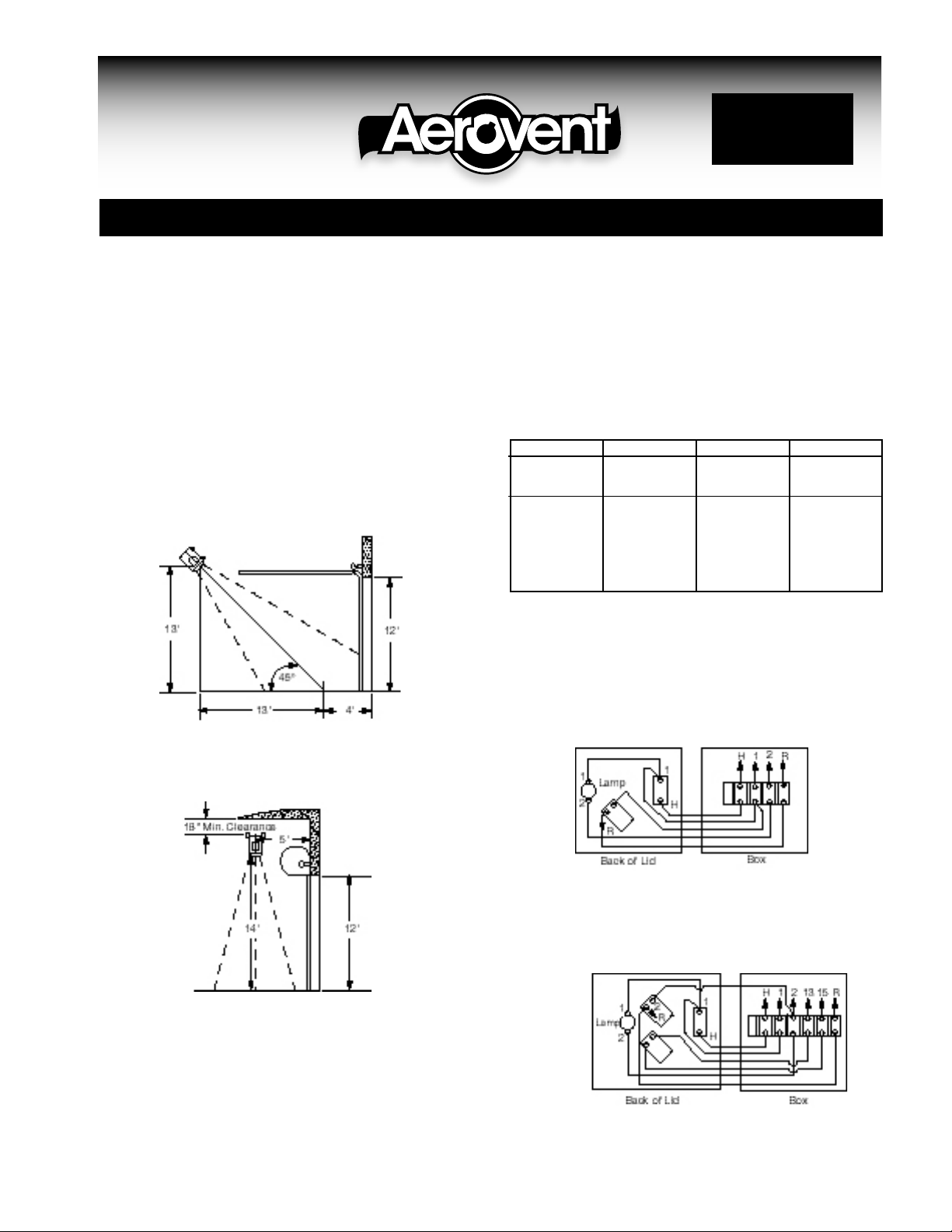
1. Install the door heater in the position required. Dimensions
can vary to suit door opening. Heaters can be mounted in
horizontal, angular or vertical position. Do not mount with
the control box upside down or on the bottom. Weight of
the unit is approximately 375 lbs.
NOTE: Negative pressure in the building will have an
affect on the unit’s ability to maintain an air curtain effect.
This should be taken into account when locating the unit.
2. Connect electrical power. If the unit does not have a built-
Typical Overhead Door
Angular Mounting Approx. 45°
3. Connect the gas supply line using the regulator furnished
with the unit. Consult your gas company service representative to determine the proper size for the gas line. This
varies according to the pressure and length of the run.
Required gas input can be determined by the chart, Fig. 1.
NATURAL. GAS INPUT NOMINAL GAS
MODEL NO. BTU TEMP. RISE PRESS.
24S728 325,000 73°F 1 oz.
NDH* 440,000 99°F 2 oz.
3/4 HP 580,000 131°F 3 oz.
440,000 66°F 2 oz.
580,000 85°F 3 oz.
24S728 680,000 102°F 4 oz.
NDH* 790,000 118°F 5 oz.
2 HP 870,000 130°F 6 oz.
990,000 148°F 7 oz.
*PDH = Propane units
4. Mount the operating station in a convenient location and
make connections to the terminal strip in the unit as indicated in Fig. 2, or Fig. 3 for units supplied with the optional high-low fire feature.
Fig. 2. Operating Station
Connect H, 1, 2, and R to terminal
Roll Top or Straight Lift Door
Vertical Mounting Used With Roll Top Doors
in disconnect switch, then an external disconnect should be
provided by the installer. Be sure power supply is the
proper voltage. These units are furnished for specified voltage.
©2000 Aerovent
strip in unit control box.
Fig. 3. Operating Station with Optional Hi-Lo Fire
Connect H, 1, 2, R, 13 and 15 to
terminal strip in unit control box.
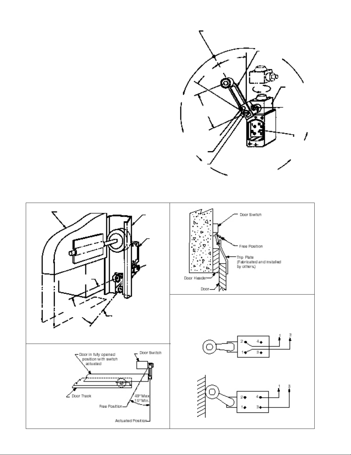
5. Mount the door switch so it will trip to close the circuit
when the door is open. The switch may be located so the
heater will come on when the door starts to open or when
fully open at the discretion of the user. See typical suggested installations.
Door Switch and Suggested Installations
The door switch may be installed with the switch in the “free”
position when the door is either opened or closed. If the
switch is mounted so that it is in the “free” position when the
door is open, use the normally-closed circuit, terminals #1 and
#2. If the switch is mounted so that it is in the “free” position
when the door is closed, use the normally-open circuit, terminals #3 and #4.
Installation #1: Floor Level Location - Switch is in “free”
position when the door is open. Use switch terminals #1 and
#2. Heater will fire when the door starts to open.
Installation #2: Overhead Location - Switch is in “free” position when the door is closed. Use switch terminals #3 and #4.
Heater will fire only when the door is completely open.
Installation #3: Overhead Location - Switch is in “free” position when the door is open. Use switch terminals #1 and #2.
Heater will fire when the door starts to open.
The unit can be operated manually with an on-off switch in
remote station or automatically from a door switch on an
“FREE” POSITION: 360°
location on actuator shaft
49°
MAXIMUM TRAVEL
3
1
⁄16" Min.
3" Max.
ALLENHEAD SCREW:
Loosen to adjust radius
of roller lever.
CLAMP PLATE
ACTUATOR
SHAFT
ADJUSTABLER
49°
ROLER LEVER
DOOR SWITCH
OPERATING
HEAD: May be
relocated four
90° positions.
LEVER LOCKING
NUT: Loosen to
to relocate “free”
position of adjustable
roller lever.
TERMINAL
CONNECTIONS:
#1 & #2 Normally
Closed
#3 & #4 Normally
Open
Door
Free Position
49° Max.
15° Min.
Door
Track
Actuated Position
INSTALLATION
NO. 1
Door
Switch
INSTALLATION
NO. 3
OIL TIGHT DOOR SWITCH
Connect to terminal 1 and 3 on terminal strip
in unit control box.
Connect as shown when switch is released
with door in open position.
Connect as shown when switch is held with
door in open position.
INSTALLATION
NO. 2
2 IM-200
 Loading...