

Aerovent IM-180 User Manual

IM-180
April 2005
General Installation, Operation and Maintenance Instructions For Aerovent Products
Fiberglass Centrifugal Fans
Aerovent solid fiberglass fans are designed for long, trouble-free service in severe
corrosive conditions. Care should be exercised during installation and operation in
order to obtain maximum life.
Inspection
1. Inspect the equipment for any shipping damage. Freight
damage claims should be filed immediately with the carrier
if any damage is noted. Remove any foreign material such as
tags or packing from any moving parts or from within the
housing.
2. Turn motor, drive and impeller by hand to see that no misalignment has taken place in shipment. (All units have been
test run before shipment.)
3. Check all bolts, fasteners, lube lines, etc., and tighten if necessary.
Installation
For satisfactory operation, a good foundation and/or support
is essential. Foundations should be level, rigid and of sufficient
mass. A concrete base with mass at least 2 to 3 times the weight
of the fan and drive is preferred. If a steel platform is used, all
supports should be sturdy, rigid and braced in all directions.
When mounting, do not distort or twist. Shim or grout
under fan base, if necessary, to see that mating parts are accurately aligned before tightening bolts to avoid applying excessive
pressures at the flanges.
Use gaskets between the fan flanges and the connecting
duct flanges to eliminate condensate leakage. A soft compress-
4. Compare the voltage, hertz and phase stamped on the motor
with the current characteristics of the line to which the
motor is to be connected.
CAUTION: Temperature limitations for use with fiberglass
fans must be carefully observed. Do not install adjacent to
steam lines or in any location where 200°F temperature may be
exceeded. Fumes carried by the ducts must also be held below
this temperature.
ible corrosion resistant gasket should be employed. It is recommended that new gaskets be used anytime a joint is to be
replaced.
For best results, a flexible connection consisting of a flexible sleeve and corrosion proof tie bands are recommended.
An access door in the scroll of the fan is convenient for quick
inspection of the fan to check for build-up of dirt on blades,
etc. Do not support the weight of the stack or duct by the inlet
or outlet connections.
Operation
1. Fans must not be operated under conditions which would
lead to the build-up of solids on the fan blades. This could
cause an unbalanced condition and lead to premature failure. (Each fan has been statically and dynamically balanced
before leaving the factory.)
2. Check alignment of the V-belt drive by means of a straightedge. Align and adjust belt tension, if necessary. An adjustable motor base is provided as standard on Arrangement 9
and 10. After adjustment, be sure adjusting bolts are tight.
(See IM Manual Bulletin 101.)
3. All fans are lubricated at the factory and have been given a
run-in test before shipment. Aerovent’s fiberglass centrifugal
©2005 Aerovent
fans are furnished as standard with a shaft hole closure consisting of a thin Teflon membrane secured with a stainless
steel plate to minimize the leakage of corrosive gases around
the bearings. However, as a further precaution against bearing contamination, a more frequent lubrication schedule
than that outlined in IM-100 is recommended.
4. Turn the wheel over by hand to make sure that it runs free
and clear. Adjust if necessary.
5. Jog the fan electrically and note rotation. Each centrifugal
fan is marked to indicate direction of rotation. Reverse electrical leads, if necessary, to obtain proper rotation.
6. Do not exceed maximum operating speed as shown in the
table below.
Max. Safe Speeds For
Wheels At 70°F Temp
SIZE CL I CL II CL III
12 3080 4005 5082
16 2425 3153 4002
20 1941 2523 3046
25 1540 2002 2372
32 1213 1576 1837
39 970 1261 1455
Correction Factors
For Max. Speed
at Various Temps
TEMP.
°F
70 1.00
100 1.00
150 0.85
200 0.55
FACTOR
Couplings
Direct-coupled fans should be checked for correct coupling
alignment before putting the unit in operation. Also, check
lubricant following manufacturer’s recommendations for type
and amount of lubricant used. For field installation, the coupling should be mounted as follows:
1. Remove dirt or rust from fan and motor shafts and coat with
grease or oil for easy mounting of coupling.
Maintenance
Regular and systematic inspection of all fan parts is the key to
good fan maintenance. Frequency of inspection is determined
by the severity of the application and local conditions. Once a
maintenance schedule is established, it should be strictly adhered
to. Regular fan maintenance should include the following:
1. Check after one day operation.
2. Check after one week operation.
3. Check periodically once a month until experience indicates
that a longer period is satisfactory.
Fan Wheel
The fan wheel must be kept reasonably clean if it is to perform
properly. Dirt or chemical deposits will usually build up on the
wheel evenly and they present no problem to performance or
operation until they become thick enough to break away in
crust-like pieces. When this happens, the wheel may be thrown
out of balance and the resulting vibration could be serious.
When removing this crustaceous accumulation, care should be
taken not to clean the fan wheel with sharp objects which might
damage the laminated surface and reduce corrosion resistance.
Should the wheel show excessive wear, it should be replaced.
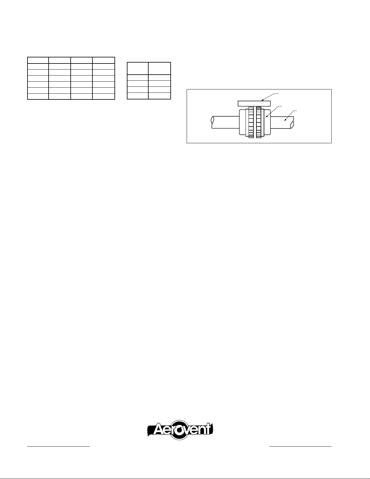
2. Mount the coupling halves on the shafts with the fans separated by the coupling manufacturer’s specified gap.
3. The coupling should be checked for parallel and angular
alignment with a straightedge and feeler gauge. Exact tolerances are specified by the coupling manufacturer.
4. Once a proper alignment is assured, complete the assembly
and lubricate the coupling before putting the unit into operation. After a short period of operation, recheck alignment.
Straightedge
Coupling
Shaft
V-Belts
On belt-driven units, check V-belt drive for proper alignment
and tension (see IM-101). If belts show wear, they should be
replaced with a matched set of belts. If unit is direct coupled,
check coupling alignment.
Fan Bearings
Check fan bearings for adequate lubrication, wear, tightness
and overheating. (See bearing section of IM-100 for lubrication
specifications.)
Fasteners
Check tightness of all nuts and bolts taking care not to overtighten nuts on encapsulated housing bolts.
Condensate Drain
If fan is equipped with a condensate drain in the housing, check
to be sure it is not clogged.
Spare Parts
A spare parts list is not supplied with the fan. There are very few parts which would ever require replacing. For
ordering these, mention part by name such as wheel, bearing or shaft and refer to model number and serial number
on label. If possible, advise order number and date of original purchase.
®
AEROVENT | WWW.AEROVENT.COM
5959 Trenton Lane N | Minneapolis, MN 55442 | Phone: 763-551-7500 | Fax: 763-551-7501
 Loading...