

Aerovent IM-176 User Manual
IM-176
June 2004
General Installation, Operation and Maintenance Instructions For Aerovent Products
Type ‘E’ Adjustable Pitch Propeller
Blade Angle Adjustment
Blades are set to the specified blade angle at the factory. If
adjustment in the field is required, use one of the following
two methods:
Preferred Method (more accurate)
1. Lay the hub on a horizontal surface with the concave (air
leaving) surfaces of the blades facing upwards.
2. Loosen the blade retaining bolts until they are finger-tight.
At this point, the blades should rotate in their sockets when
grasped firmly and twisted, but not turn on their own.
3. Place an angle meter across the two blade angle position
marks on a blade. See Figure 1.
4. Twist the blade to the desired blade angle.
5. Repeat steps 3 and 4 for the remaining blades.
6. Re-tighten the blade retaining bolts to the torque shown in
Table 1. Work in a star pattern, working your way up to the
desired torque in steps. Tightening one bolt to the full
torque before moving on to the next can crack the hub.
Alternate Method
1. Loosen the blade retaining bolts until they are finger-tight.
Table 1.
TORQUE (ft. lbs.)
FAN HUB
SIZE DIA.
14 - 24 6" H 17 7.5
30 - 36 9" P 30 13
42 - 48 12" P 75 13
42 - 48 12" Q 75 24
Figure 1.
BUSHING BLADE BUSHING
BOLT BOLT
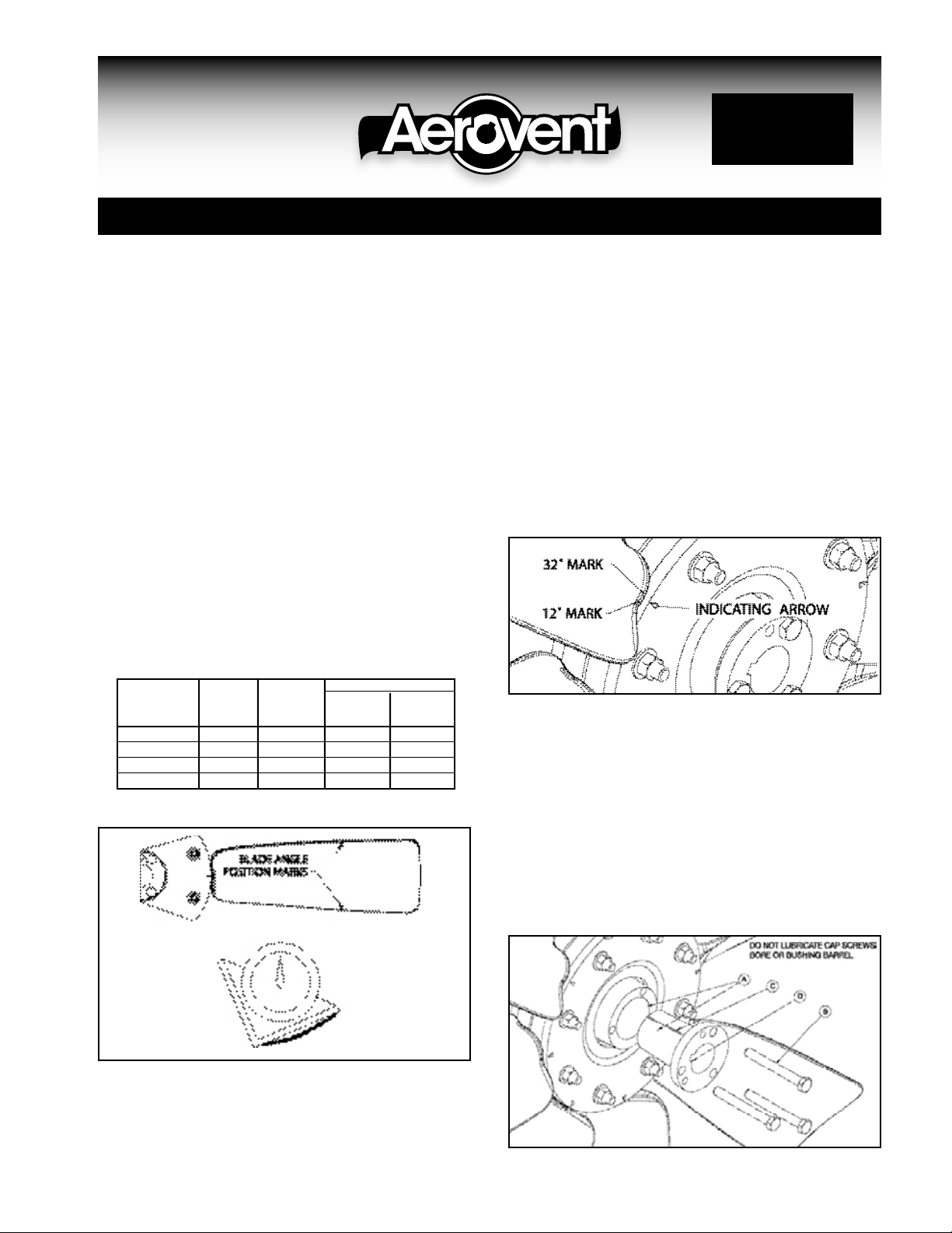
cating marks at 5° increments are in between the two longer
marks. See Figure 2 below.
3. Twist each blade to the desired blade angle.
4. Re-tighten the blade retaining bolts to the torque shown in
Table 1. Work in a star pattern, working your way up to the
desired torque in steps. Tightening one bolt to the full
torque before moving on to the next can crack the hub.
Mounting the Propeller Assembly
on the Shaft
Type ‘E’ propellers are furnished with hubs that have a tapered
bore. A split-tapered bushing is used for mounting the propeller assembly to the shaft. When properly assembled, the bush-
Figure 2.
ing grips the hub and the shaft with a positive clamping action.
See Figure 3 below.
A. The bushing barrel and the bore of the propeller hub are
tapered. This assures concentric mounting and a true running propeller.
B. The cap screws, when tightened, lock the bushing in the
propeller.
C. The bushing is split so that when the locking cap screws
force the bushing into the tapered bore, the bushing grips
the shaft with a positive clamping fit. This will withstand
vibration and punishing loads without loosening.
D. The propeller and bushing assembly is keyed to the shaft
Figure 3.
At this point, the blades should rotate in their sockets when
grasped firmly and twisted, but not turn on their own.
2. Angle setting marks on the blade line up with an indicating
arrow on the hub. There are two long marks on the blade,
one for 12° blade angle and another for 32°. Shorter indi-
©2004 Aerovent

and held in place by compression. This gives added driving
strength.
Put the bushing loosely into the propeller. Do not press or
drive. Start the cap screws by hand, turning them just enough
to engage the threads in the tapped holes on the propeller. Do
not use a wrench at this time. The bushing should be loose
enough in the propeller to move slightly. Be sure the shaft and
keyway are clean and smooth. Check the key size with both the
shaft and bushing keyways. Slide the propeller and bushing
assembly onto the shaft, making allowance for endplay in the
shaft to prevent rubbing. Do not force the propeller and bushing onto the shaft. If it does not go on easily, check the shaft,
bushing, and key sizes.
Tighten the caps screws progressively with a wrench. Do this
evenly as in mounting an automobile wheel. Take a part turn
on each cap screw successively until all are tightened to the
torque shown in Table 1.
These cap screws force the tapered bushing into the hub,
which in turn compresses the bushing on to the shaft.
WARNING: Do not attempt to pull the bushing flange flush
with the hub end. There should be 1/8" to 1/4" clearance
when tightened.
Removing the Propeller Assembly from
the Shaft
The propeller is easily removed from the shaft by inserting and
tightening two of the cap screws into the tapped holes in the
bushing flange. This forces the bushing loose from the propeller and releases the compression so that the entire assembly
will slide off the shaft.
1. Remove all the cap screws from the propeller and hub
assembly.
2. Start the cap screws into the threaded holes in the bushing
flange.
3. Tighten each bolt part of a turn successively to force the
propeller off the bushing.
4. Pull the bushing off the shaft. If the assembly has been in
place for some time, it may be necessary to use a wheel
puller to remove the bushing. Never use a wheel puller on
the propeller.
®
AEROVENT | WWW.AEROVENT.COM
5959 Trenton Lane N | Minneapolis, MN 55442 | Phone: 763-551-7500 | Fax: 763-551-7501
5MPP06/04
 Loading...