

Aerovent IM-173 User Manual
®
IM-173
June 1997
General Installation, Operation and Maintenance Instructions For Aerovent Products
Adjustable Pitch Propeller Taper-Lock Hub
Reversible Propeller With Thru-Bolt Construction
Assembly Procedures
1. Lay hub on a horizontal surface with openings of shank
sockets (Fig. 3) facing up. This is normally the discharge
side of the assembly.
2. Lay blade shank in socket with discharge side of the blade
up. The discharge side of the blade is the side with the
angle setting mark. Line up the index mark on the blade
with the proper angle mark on the end of the shank socket
(Figs. 2 and 4) on the underside of assembly.
3. Place cap over blade shank with beveled end toward center.
Install U-bolts and elastic nut stops. Before tightening lock
nuts, pull the blade outward to set the key against the keyway and check angle setting (Fig. 3).
4. Tighten elastic stop nuts evenly and torque to the following
foot-pounds:
PROPELLER HUB U-BOLT TORQUE
DIA. DIA. SIZE (FT/LBS)
54" – 72" 14" 1/2" 20
81" – 96" 18" 3/4" 45
5. Check angle setting to be sure it has not changed during
assembly. If so, loosen lock nuts and reset angle. Tighten
nuts again to proper torque. Do not over-tighten. Be sure
to tighten U-bolts evenly.
Setting Angle With Protractor (optional)
Under most conditions, the preceding assembly procedure
using the index marks is of sufficient accuracy. When greater
accuracy is desired, use a level bubble protractor. Before the
final tightening of the nuts, set the protractor on the angle
setting mark. (The hub and blade assembly must be level for
accurate setting.) Adjust the angle by tapping the shank end
with a mallet. Tighten lock nuts to proper torque. Again check
the angle setting. Rotate propeller to check angle on each blade
in the same location.
Propellers may be assembled so the cap side of the hub is
the inlet side (reverse bore). If blades do not have the index
mark on the discharge side, it is then necessary to adjust the
blade angle with a protractor.
The hub and blades are balanced separately. The weight
distribution throughout the length of the blade varies slightly.
Therefore, the balance is to a constant moment and blades
may be assembled at random even though the weights are
slightly different.
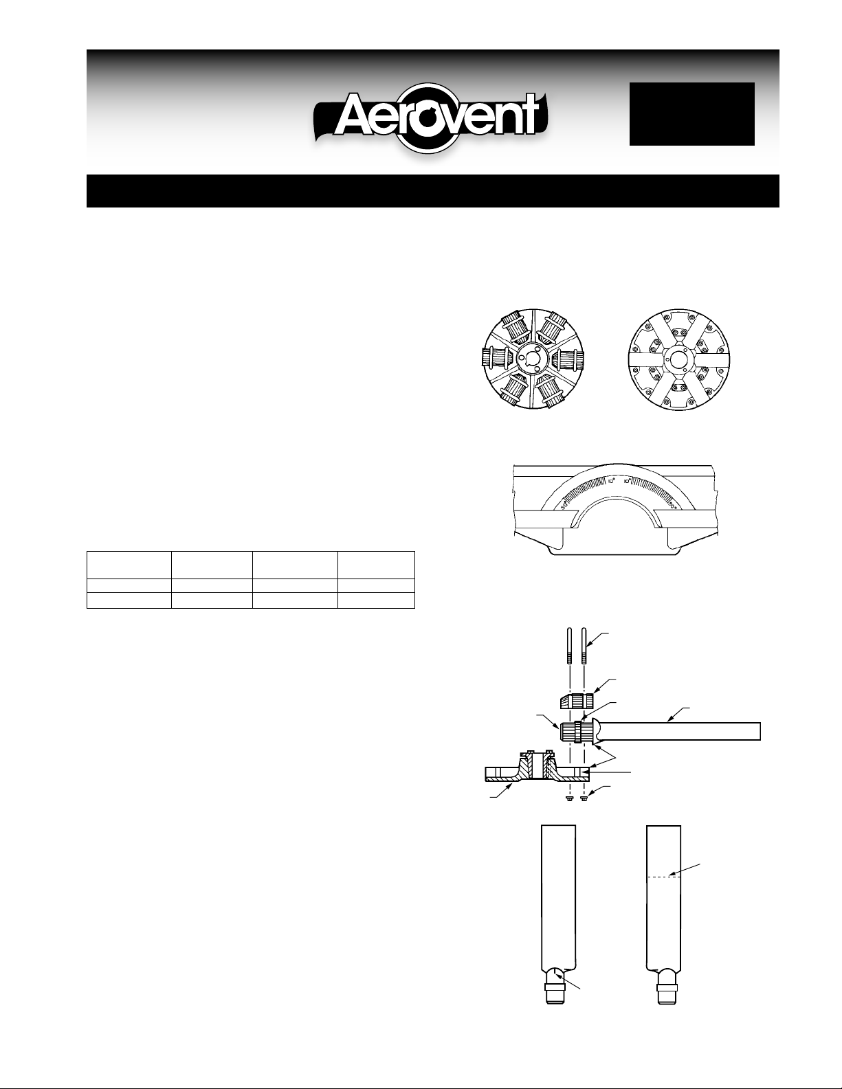
Fig. 1
Cap and U-Bolt Side Lock Nut Side
Fig. 2
Angle setting index on shank socket. Marked from 10° through 50°. Each
mark is 2°. When hub is viewed as shown above, scale on left side
should be used for right-hand propeller and scale on right side should
be used for left-handed propellers.
Fig. 3
Blade
Shank
Hub
U-Bolts
Cap
Key
Index Marks
Keyway
Elastic Stop Nuts
Blade
Fig. 4
Angle
Setting
Mark
Index
Mark
Inlet Side Discharge Side
©2005 Aerovent
Installation Instructions For Propellers Equipped With
Browning Malleable Iron Split Taper Bushings
Aerovent adjustable pitch propellers are furnished with hubs
that have a tapered bore. A split taper bushing is used for
mounting the propeller assembly to the shaft. When properly
assembled, the bushing grips the hub and the shaft with a
positive clamping action. The split taper bushing is always
mounted on the discharge or cap side of the hub unless the
propeller has been ordered with a reverse bore.
A. Bushing barrel and bore of propeller hub are tapered. This
assures concentric mounting and a true running propeller.
B. Capscrews, when tightened, lock bushing in propeller. Use
plated capscrews threaded full length (see table below).
BUSH CAPSCREW TORQUE
NO. SIZE THREADS/IN LENGTH (FT./LBS.)
Q2
R2
C. Bushing is split so that when the locking capscrews force
bushing into tapered bore, the bushing grips the shaft with
a positive clamping fit. This will withstand vibration and
punishing loads without being loosened.
D. Propeller and bushing assembly is keyed to shaft and
held in place by compression. This gives added driving
strength.
Installation Instructions
Put bushing loosely into propeller. Do not press or drive.
Insert the capscrews through the untapped holes in the bushing and through the hub. Start the self-locking nuts on the
bolts but do not tighten.
Be sure shaft and keyway are clean and smooth. Check key
size with both shaft and bushing keyways. Slide propeller and
bushing assembly onto shaft, making allowance for end play
of shaft to prevent rubbing. Do not force propeller and bushing onto shaft. If it does not go on easily, check shaft, bushing
and key sizes.
Tighten capscrews progressively with wrench while holding self-locking nuts securely with wrench. Do this evenly as
in mounting an automobile wheel. Take a part turn on each
capscrew successively until all are tight.
3
⁄8" 16 41⁄2" 24
3
⁄8" 16 6" 24
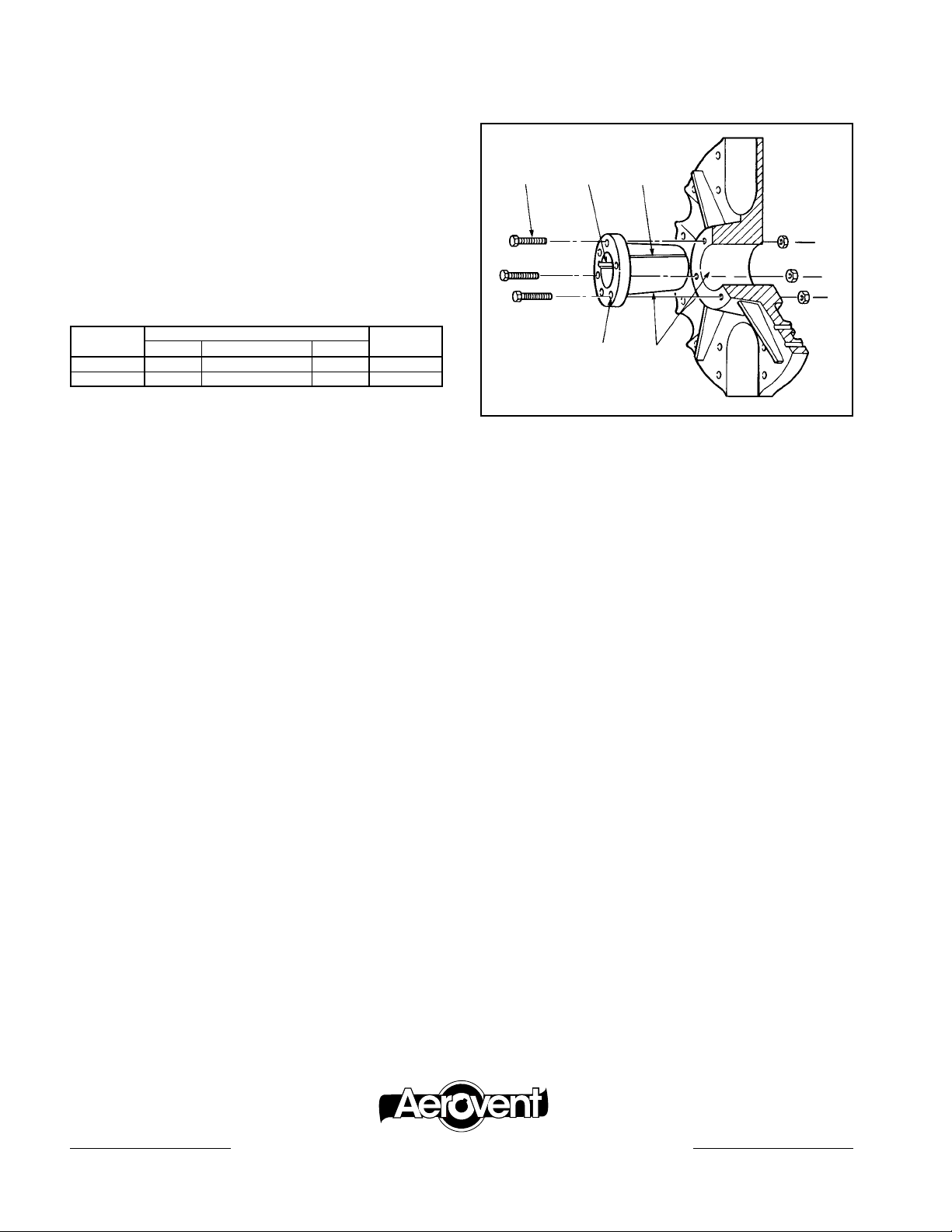
B
DO NOT LUBRICATE
CAPSCREWS, BORE, OR
BUSHING BARREL.
D
C
E
A
These capscrews force the taper bushing into the hub
which in turn compresses the bushing onto the shaft. This
makes a positive clamping fit. The torque must not exceed 24
ft. lbs. for Q bushings and for R bushings.
WARNING: Do not attempt to pull bushings flange flush
with hub end. There should be 1∕8" to 1∕4" clearance when
tightened.
Removing Propeller Assembly From Shaft
1. Remove all three capscrews and self-locking nuts from
propeller and hub assembly.
2. Start capscrews into the threaded holes in the bushing
flange.
3. Tighten each bolt part of a turn successively to force the
propeller off the bushing.
4. Pull the bushing off the shaft. If the assembly has been in
place some time, it may be necessary to use a wheel puller
to remove the bushing. Never use a wheel puller on the
propeller.
For propeller dimensions, see drawing R-8709.
®
AEROVENT | WWW.AEROVENT.COM
5959 Trenton Lane N | Minneapolis, MN 55442 | Phone: 763-551-7500 | Fax: 763-551-7501
 Loading...