

Aerovent IM-172 User Manual
IM-172
August 2014
General Installation, Operation and Maintenance Instructions For Aerovent Products
Propeller Wall Fans
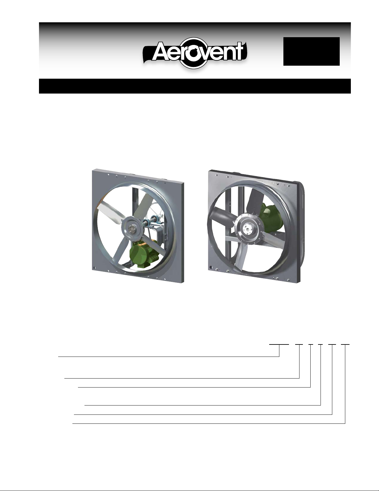
Models: BSBP, BSDDP
Aerovent Catalog 172 provides additional information on this equipment. This catalog
can be found at www.aerovent.com or by contacting your local Aerovent sales representative.
BSBP BSDDP
Model Nomenclature
Model
BSDDP = Wall Propeller Fan, Direct Drive
BSBP = Wall Propeller Fan, Belt Driven
Fan Size
Propeller Type
B = Backswept
Hub Designation
Blade Count
Blade Angle
BSDDP - 24 - B - 1 - 05 - 25
©2014 Aerovent

Receiving, Unpacking & Inspection
When the equipment is received all items should be
carefully checked against the bill of lading to be sure all
crates and cartons have been received. Before accepting
delivery, carefully inspect each carton or crate for
visible shipping damage. If any damage is noticed, the
carrier should make the proper notation on the delivery
receipt acknowledging the damage. Make notations of
all damage on all copies of the bill of lading and have
all copies countersigned by the delivering carrier. The
carrier should also fill out a Carrier Inspection Report.
The factory Traffic Department should then be contacted.
File claim for damage with the carrier. Physical damage
to the unit after acceptance is not the responsibility of
Aerovent.
Unpack each carton or crate and verify that all required
parts and proper quantities of each item have been
received. Refer to drawings for part descriptions. Report
shortages or missing items to your local representative
to arrange for replacement parts.
Storage
If fans are stored for any length of time, they should
be stored in a clean, dry location to prevent rust and
corrosion. Outdoor storage is not recommended. When
outdoor storage is necessary, fans should be protected
from the elements as completely as possible. Cover the
fan inlet and outlet and keep motors dry and clean.
For extended storage (more than 3 months) motor shafts
and bearings should be rotated monthly. If stored longer
Due to availability of carriers and truck space, it is not
possible to guarantee that all items will be shipped
together. Verification of shipments must be limited to
only those items on the bill of lading.
The unit nameplate must be checked to make sure
the voltage agrees with the power supply available.
CAUTION: Sheet metal parts, screws, clips and simiar
items inherently have sharp edges, and it is necessary
that the installer and service personnel excercise
caution.
The installation of this equipment shall be in accordance
with the regulations of authorities having jurisdiction and
all applicable codes. This equipment is to be installed
by an experienced installation company and fully trained
personnel. The mechanical installation of the exhaust
ventilator consists of making final connections between
the unit and building services, duct connections.
than 6 months, bearing grease in motor and fan should
be purged and replaced with compatible grease. Belts
should be rechecked for proper tension. Storage records
should be kept to assure proper maintenance. The
factory can advise warranty centers to provide motor
and bearing service if needed.
Limitation of Warranties and Claims
Seller warrants to the original purchaser that the
goods sold hereunder shall be free from defects in
workmanship and material under normal use and service
(except in those cases where the materials are supplied
by the buyer) for a period of one year from the date of
original installation or eighteen (18) months from the date
of shipment, whichever occurs first. The liability of seller
under this warranty is limited to replacing, repairing, or
issuing credit (at cost, F.O.B. factory and at seller’s
discretion) for any part or parts which are returned by
buyer during such period provided that:
a. seller is notified in writing within ten (10) days
following discovery of such defects by buyer, or
within ten (10) days after such defects should
reasonably have been discovered, whichever is
less;
b. the defective unit is returned to seller, transportation
charges prepaid by buyer;
c. payment in full has been received by seller or said
products;
d. seller’s examination of such unit shall disclose to its
satisfaction that such defects have not been caused
by misuse, neglect, improper installation, repair,
alteration, act of God, or accident.
No warranty made hereunder shall extend to any
seller product whose serial number is altered, effaced
or removed. Seller makes no warranty, express or
implied, with respect to motors, switches, controls,
or other components of seller’s product, where such
components are warranted separately by their respective
manufacturers. THIS WARRANTY IS EXPRESSLY IN LIEU
OF ALL OTHER WARRANTIES, EXPRESS OR IMPLIED,
WHETHER STATUTORY OR OTHERWISE, INCLUDING
ANY IMPLIED WARRANTY OF MERCHANTABILITY OR
FITNESS FOR A PARTICULAR PURPOSE. In no event
shall seller be liable to buyer for indirect, incidental
collateral, or consequential damages of any kind.
(BUYER’S FAILURE TO PAY THE FULL AMOUNT DUE
WITHIN SIXTY (60) DAYS OF DATE OF INVOICE SHALL
OPERATE TO RELEASE SELLER FROM ANY AND ALL
LIABILITY OR OBLIGATION ARISING PURSUANT TO
ANY WARRANTY, EXPRESS OR IMPLIED, WHETHER
STATUTORY OR OTHERWISE, INCLUDING ANY IMPLIED
WARRANTY OR MERCHANTABILITY OR FITNESS FOR
A PARTICULAR PURPOSE, MADE IN CONNECTION
WITH ANY CONTRACT FORMED HEREUNDER. BUYER
AGREES THAT SUCH FAILURE TO PAY SHALL
CONSTITUTE A VOLUNTARY WAIVER OF ANY AND ALL
SUCH WARRANTIES ARISING PURSUANT TO SUCH
CONTACT.)
2 Aerovent IM-172
Electrical Connection
1. Connect supply wiring to a disconnect switch.
Check the wiring diagrams on the motor for connections.
2. The motor is factory set at the voltage marked on
the fan nameplate. Check the line voltage with the
nameplate voltage and wiring diagrams.
3. The main power wiring should be sized for the
ampacity shown on the dataplate. Size wires in
accordance with the ampacity tables in Article 310
of the National Electrical Code. If long wires are
required, it may be necessary to increase wire size
to prevent excessive voltage drop. Wires should be
sized for a maximum of 3% voltage drop.
CAUTION: Use copper conductors only.
CAUTION: Protect wiring from sharp edges. Leave
some slack in the line to prevent damage.
4. (Optional) Disconnect switches are not fused. The
power leads must be protected at the point of distribution in accordance with the fan dataplate.
Check, Test & Start Procedure
5. On fans without a thermal protector integral to the
motor (refer to unit or motor dataplate to determine
if protector is present) a separate overload device
is required. Refer to Sections 430-32 of the N.E.C.
for sizing.
6. All units must be electrically grounded in accordance
with local codes or, in the absence of local codes,
with the latest edition of the National Electrical
Code (ANSI/NFPA 70). A ground lug is provided as
standard in the unit terminal box. Size grounding
conductor in accordance with Table 250-95 of the
National Electrical Code. DO NOT use the ground
lug for connecting a neutral conductor.
7. Supply voltage to the power ventilator should not
vary by more than 10% of the value indicated
on the unit dataplate. Phase unbalance must not
exceed 2%.
WARNING: Failure of motor due to operation on
improper line voltage or with excessive phase unbalance constitutes product abuse and may cause
severe damage to the unit’s electrical components.
WARNING
Electric shock hazard. Could cause severe injury or
death. Failure to bond the frame of this equipment
to the building electrical ground by use of the
grounding terminal provided or other acceptable
means may result in electrical shock. Disconnect
electric power before servicing equipment. Service
to be performed only by qualified personnel.
BEFORE START-UP: Disconnect power to this unit
before servicing the unit.
1. Check to verify that the propeller is free to rotate.
2. Verify that supply voltage on the line side of disconnect agrees with voltage on fan data plate and is
within the 10% utilization voltage.
3. Apply power to unit and check rotation of propeller
with the directional arrow on the unit.
WARNING: Rotation is critical. If allowed to operate
in the wrong direction, the motor will overload and
burn out.
WARNING: Especially check three-phase units for
rotation. For three-phase, rotation can be changed by
interchanging any two of the three line leads. If unit is
checked on temporary wiring, it should be rechecked
when permanently installed. Motor burn-out or tripped
overload protection devices are usually the result of
wrong rotation.
4. Electrical Input Check: Perform check of fan ampere
draw and verify that motor nameplate amps are not
exceeded. Take into account the service factor range
if motor is nameplated above a 1.0 service factor.
5. Fan RPM should be checked and verified with a
tachometer.
Aerovent IM-172 3
Speed Control Installation
The controller is designed to start the motor at high
speed and will then slow down. This gives the motor
good starting characteristics.
Speed control is available using 115/60/1 open type
PSC or shaded pole motors.
Installation
Connect control in series with motor and line voltage
(115V only). Never connect across line. See Figure 1.
Minimum Speed Setpoint
All controls are factory set to 65V±3V output as standard with an input voltage of 120V. If different minimum
speed is desired, the control may be adjusted by turning minimum speed pot clockwise to decrease minimum
speed and counterclockwise to increase minimum speed.
Refer to Figure 2.
Warning: If minimum speed is readjusted, verify unit
ampere draw does not exceed motor nameplate amps.
Do not operate unit in range where amp draw exceeds
motor nameplate.
Caution: These motors operate more efficiently in the
ranges set from the factory. Operating motor outside
these ranges (see Table 2) may cause motor to run
hotter and substantially shorten motor life.
Note: Lowering the minimum speed setpoint may
adversely affect motor start-up characteristics.
Warning: Certain failure modes of solid-state controls
such as half-waving can cause high levels of DC, motor
overheating and motor burn-out. Therefore, a thermal
overload protection (integral with motor) is required to
limit the maximum motor temperature under such a
failure.
Note: Do not allow any sleeve bearing motor to
operate below 500 RPM. Operation below 500 RPM will
substantially shorten bearing life.
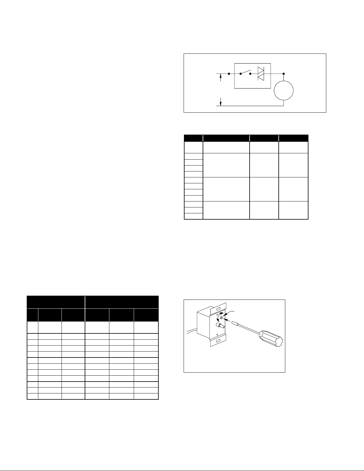
Figure 1. Connection Diagram, Speed Control
SPEED CONTROLLER
AC
LINE
(115V)
SWITCH TRI-AC
MOTOR
Table 2. Speed Controller RPM Range
HP RPM MAX. RPM MIN. RPM
1/8
1/8
1/6
1/4
1/2
1/6
1/4
1/2
1/3
1/2
3/4
NOTES:
1. Speed control available only with 115/60/1 open motors (thermally
2. Three-speed motor (multiple tap winding).
3. Speed control should not be connected to low speed tap on motor
4. Speed control connected to high speed tap on motor.
5. Speed control connected to medium speed tap on motor.
1650/1500/1350
1140 1140 900
1
1725 1725 1200
protected).
because of starting characteristics.
2,3
860 860 500
1650
1500
4
5
1300
950
4
5
Table 1. Speed Controller Size
MOTOR
HP RPM VOLTAGE
1650/1500/
1/8
1350
1/8 860 115V X
1/6 860 115V X
1/4 860 115V X
1/2 860 115V X
1/6 1140 115V X
1/4 1140 115V X
1/2 1140 115V X
1 1140 115V X
1/3 1725 115V X
1/2 1725 115V X
3/4 1725 115V X
115V X
SPEED CONTROLLER
DESIGNATION / FLA
KBWC-15K
5 AMP
KBWC-110
10 AMP
KBWC-115
15 AMP
Figure 2. Low End Setpoint Adjustment
SETPOINT
ADJUSTMENT
SCREW
NOTE: 5 amp model shown. On 10 and 15 amp
models, adjustment is made through clearance
hole in heat sink.
4 Aerovent IM-172
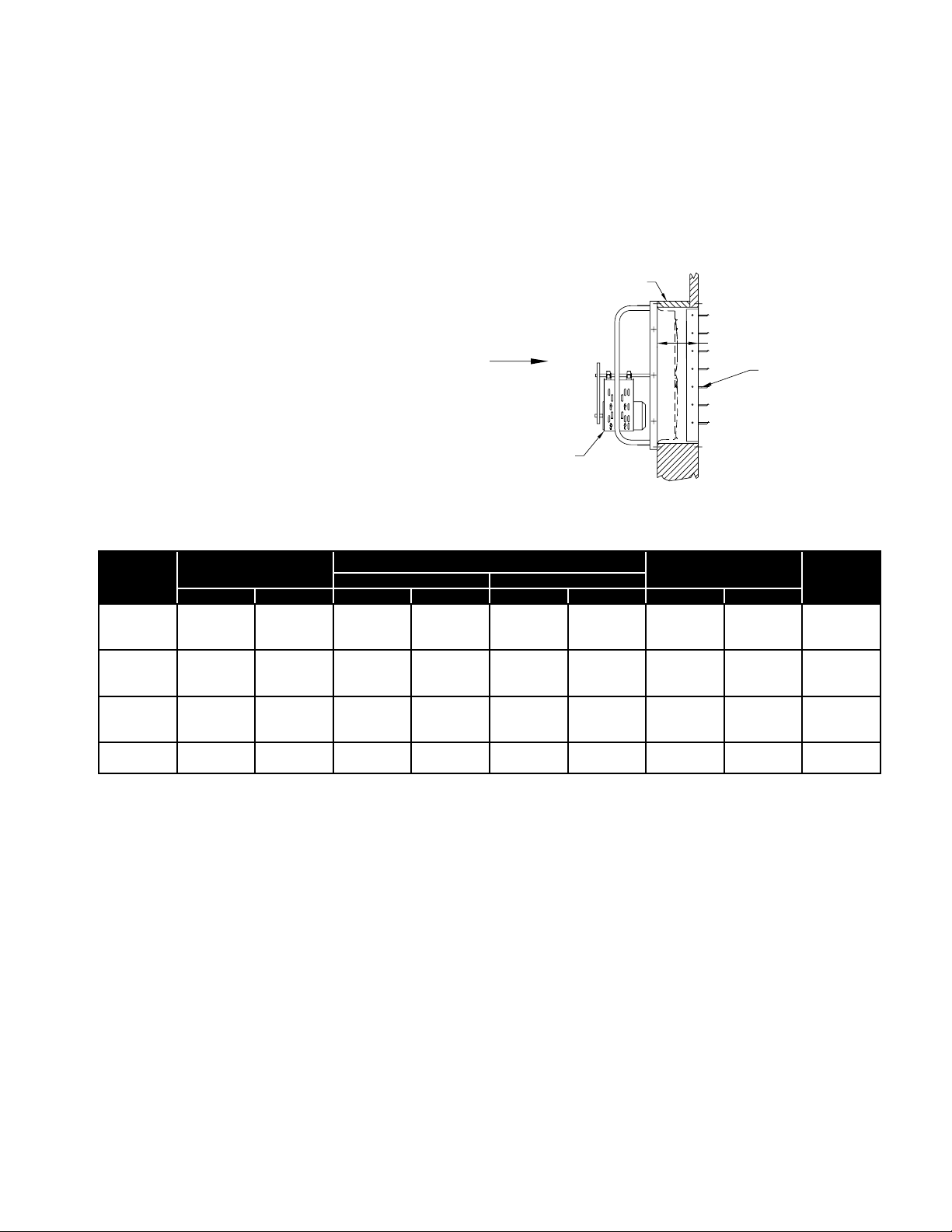
Panel Installation (without accessories) — BSBP & BSDDP
WALL OPENING REQUIREMENTS
Wall opening size and the distance between propeller and damper are two important dimensions for fan installation.
Fans mounted to the wall require a different wall opening size than those mounted in collars or wall boxes. Propellerto-damper distance (M) is important to reduce turbulance at the damper which may lead to premature failure, and to
prevent the propeller blades from hitting the actuator on motorized damper units. Use general installation procedure
from page 4.
To achieve the minimum 'M' dimension,
this installation requires a spacer (by others)
SPACER
(BY OTHERS)
between the fan and the wall.
If the wall is equal to or greater than the
minimum 'M' dimension, the fan can be
mounted directly to the wall.
PROP
SIZE
14 -- 17.00 -- 14.50 -- 17.50 -- 14 x 14
18 -- 22.00 -- 19.50 -- 22.50 -- 19 x 19
21 25.00 25.00 22.50 22.50 25.50 25.50 22 x 22 22 x 22
30 36.00 36.00 33.50 33.50 36.50 36.50 33 x 33 33 x 33
36 42.00 42.00 39.50 39.50 42.50 42.50 39 x 39 39 x 39
48 54.00 54.00 51.50 51.50 54.50 54.50 51 x 51 51 x 51
54 60.00 -- 57.50 -- 60.50 -- 57 x 57 -60 66.00 -- 63.50 -- 66.50 -- 63 x 63 --
PANEL SQ.
BSBP BSDDP BSBP BSDDP BSBP BSDDP BSBP BSDDP
SURFACE MOUNT RECESS (IN WALL)
WALL OPENING (MIN.)
AIR
FLOW
FAN
MIN
DAMPER SIZE
BACKDRAFT
DAMPER
'M'
(MIN.)
16.0016 -- 20.00 -- 17.50 -- 20.50 -- 17 x 17
16.0024 28.00 28.00 25.50 25.50 28.50 28.50 25 x 25 25 x 25
16.0042 48.00 48.00 45.50 45.50 48.50 48.50 45 x 45 45 x 45
19.00
Aerovent IM-172 5
 Loading...