

Aerovent IM-167 User Manual
®
IM-167
August 2014
General Installation, Operation and Maintenance Instructions For Aerovent Products
Aerovent Catalog 340 provides additional information on this equipment. This catalog can be found at www.aerovent.
com or by contacting your local Aerovent sales representative.
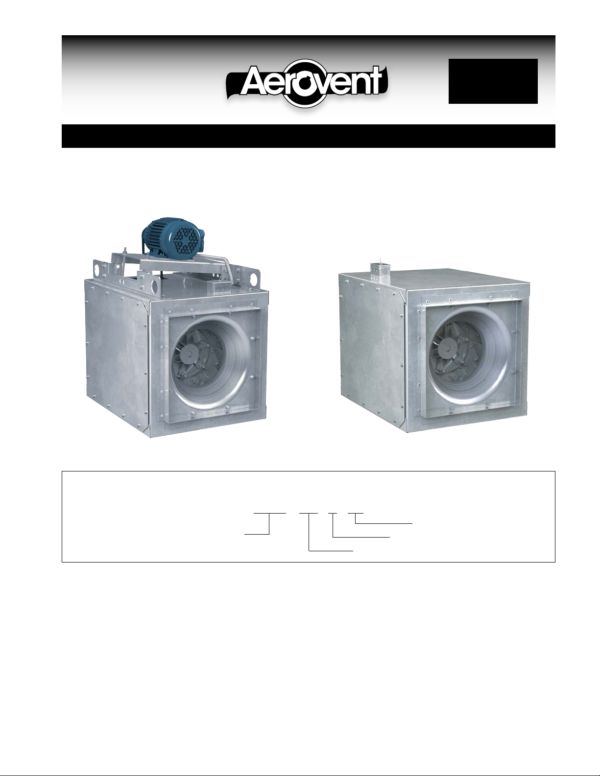
Centrifugal Square Inline Fans
Models SCBD – 080A through 402A Models SCDD – 080A through 165A
Nomenclature
SCBD - 120 A HP
SCBD = Belt Driven Centrifugal Inline
SCDD = Direct Drive Centrifugal Inline
Size
High Pressure
Design Vintage
Receiving, Inspection, & Unpacking
When the equipment is received all items should be
carefully checked against the bill of lading to be sure all
crates and cartons have been received. Before accepting delivery, carefully inspect each carton or crate for
visible shipping damage. If any damage is noticed, the
carrier should make the proper notation on the delivery
receipt acknowledging the damage. Make notations of all
damage on all copies of the bill of lading and have all
copies countersigned by the delivering carrier. The carrier should also fill out a Carrier Inspection Report. The
factory Traffic Department should then be contacted.
File claim for damage with the carrier. Physical damage
to the unit after acceptance is not the responsibility of
Aerovent.
©2014 Aerovent
Unpack each carton or crate and verify that all required
parts and proper quantities of each item have been
received. Refer to drawings for part descriptions. Report
shortages or missing items to your local representative
to arrange for replacement parts.
Due to availability of carriers and truck space, it is not
possible to guarantee that all items will be shipped
together. Verification of shipments must be limited to
only those items on the bill of lading.
The unit nameplate must be checked to make sure the
voltage agrees with the power supply available.

General Installation
CAUTION: Sheet metal parts, screws, clips and similar
items inherently have sharp edges, and it is necessary
that the installer and service personnel exercise caution.
The installation of this equipment shall be in accordance
with the regulations of authorities having jurisdiction and
with all applicable codes.
Electrical Connection
This equipment is to be installed by an experienced
installation company and fully trained personnel.
The mechanical installation of the inline centrifugal fan
consists of making final connections between the unit,
building services, and duct connections.
1. Connect supply wiring to the disconnect switch
(non-fused standard). Check the wiring diagrams on
the motor for connections.
2. The motor is factory set at the voltage marked on
the fan nameplate. Check the line voltage with the
nameplate voltage and wiring diagrams.
3. The main power wiring should be sized for the
ampacity shown on the dataplate. Size wires in
accordance with the ampacity tables in Article 310
of the National Electrical Code. If long wires are
required, it may be necessary to increase wire size
to prevent excessive voltage drop. Wires should be
sized for a maximum of 3% voltage drop.
CAUTION: Use copper conductors only.
CAUTION: Protect wiring from sharp edges. Leave
some slack in the line to prevent damage.
4. Disconnect switches are not fused. The power leads
must be protected at the point of distribution in
accordance with the fan dataplate.
5. On fans without a thermal protector integral to the
motor (refer to unit or motor dataplate to determine
if protector is present) a separate overload device
is required. Refer to Sections 430-32 of the N.E.C.
for sizing.
6. All units must be electrically grounded in accordance
with local codes or, in the absence of local codes,
with the latest edition of the National Electrical
Code (ANSI/NFPA 70). A ground lug is provided as
standard in the unit terminal box. Size grounding
conductor in accordance with Table 250-95 of the
National Electrical Code. DO NOT use the ground
lug for connecting a neutral conductor.
7. Supply voltage to the inline fan should not vary by
more than 10% of the value indicated on the unit
dataplate. Phase unbalance must not exceed 2%.
WARNING: Failure of motor due to operation on
improper line voltage or with excessive phase unbalance constitutes product abuse and may cause
severe damage to the unit’s electrical components.
2 Aerovent IM-167

Check, Test & Start Procedure
W
H
E
E
L
R
O
T
A
T
I
O
N
FAN
WHEEL
WARNING
Electric shock hazard. Could cause severe injury or
death. Failure to bond the frame of this equipment
to the building electrical ground by use of the
grounding terminal provided or other acceptable
means may result in electrical shock. Disconnect
electric power before servicing equipment. Service
to be performed only by qualified personnel.
BEFORE START-UP: Disconnect power to this unit
before servicing the unit.
1. Check to verify that the wheel is free to rotate.
2. For optimum fan performance make sure that the
wheel to inlet venturi overlap is maintainted. See
Table 1.
3. Verify that supply voltage on the line side of disconnect agrees with voltage on fan data plate and is
within the 10% utilization voltage.
4. Apply power to unit and check rotation of wheel with
the directional arrow on the unit. See Table 2.
WARNING: Rotation is critical. If allowed to operate
in the wrong direction, the motor will overload and
burn out.
WARNING: Check units for rotation. For three-phase,
rotation can be changed by interchanging any two of
the three line leads. If unit is checked on temporary
wiring, it should be rechecked when permanently
installed. Motor burn-out or tripped overload protection devices are usually the result of wrong rotation.
5. Electrical Input Check: Perform check of fan ampere
draw and verify that motor nameplate amps are not
exceeded. Take into account the service factor range
if motor is nameplated above a 1.0 service factor.
6. Fan RPM should be checked and verified with a
tachometer.
7. Units with Speed Control (Direct Drive): Verify that
speed controller gives desired operating range of
RPM. If minimum speed value is not desired, it may
be adjusted. See page 4.
NOTE: The fan was balanced at the factory to be
within stringent vibration levels before shipment.
However, there are several things that may cause
vibration, such as rough handling in shipment and
installation, weak foundations and alignments.
Table 1. Wheel to Inlet Venturi
MODEL OVERLAP
SCBD
SCDD
0.50
0.50
Table 2. Wheel Rotation*
MODEL CW CCW
SCBD
SCDD
* Wheel rotation is determined when viewed from discharge.
Note: On fans with three phase motors the wheel rotation can
be changed by reversing any two power leads.
all ---
--- all
Figure 1. Fan Wheel Rotation - View from Discharge
Note: CW rotation shown, CCW rotation is similar but opposite.
Aerovent IM-167 3
Speed Control Installation
(Model SCDD - optional)
Speed control is available for SCDD models using
115/60/1 open type PSC or shaded pole motors.
Installation
Connect control in series with motor and line voltage
(115V only). Never connect across line. See Figure 2.
Minimum Speed Setpoint
All controls are factory set to 65V±3V output as standard with an input voltage of 120V. If different minimum
speed is desired, the control may be adjusted by turning minimum speed pot clockwise to decrease minimum
speed and counterclockwise to increase minimum speed.
Refer to Figure 3.
Warning: If minimum speed is readjusted, verify unit
ampere draw does not exceed motor nameplate amps.
Do not operate unit in range where amp draw exceeds
motor nameplate.
Caution: These motors operate more efficiently in the
ranges set from the factory. Operating motor outside
these ranges (see Table 3) may cause motor to run
hotter and substantially shorten motor life.
Note: Lowering the minimum speed setpoint may
adversely affect motor start-up characteristics.
Warning: Certain failure modes of solid-state controls
such as half-waving can cause high levels of DC, motor
overheating and motor burn-out. Therefore, a thermal
overload protection (integral with motor) is required to
limit the maximum motor temperature under such a
failure.
Note: Do not allow any sleeve bearing motor to operate
below 500 RPM. Operation below 500 RPM will substantially shorten bearing life.
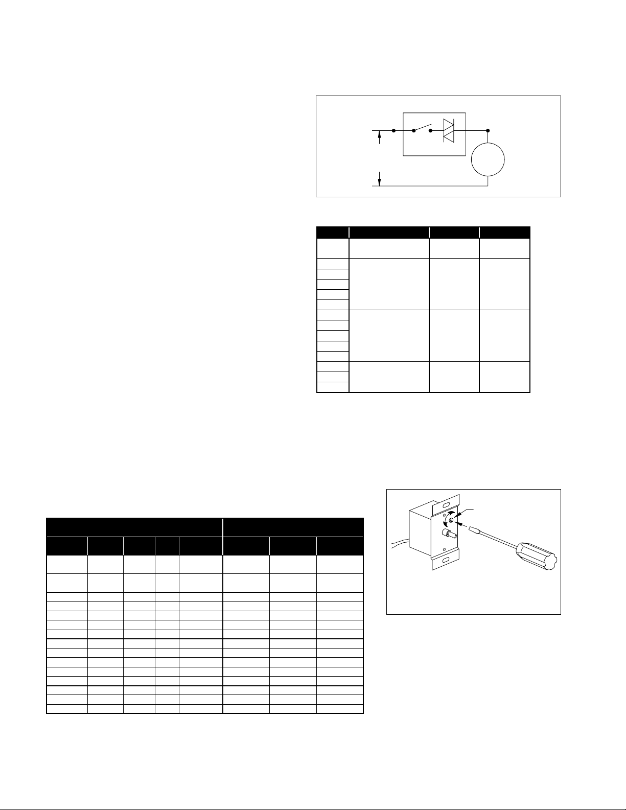
Figure 2. Connection Diagram, Speed Control
SPEED CONTROLLER
AC
LINE
(115V)
SWITCH TRI-AC
MOTOR
Table 3. Speed Controller RPM Range
HP RPM MAX. RPM MIN. RPM
1/30
1/8
1/15
1/8
1/6
1/4
1/2
1/8
1/6
1/4
1/2
1/3
1/2
3/4
NOTES:
➀ Speed control available only with 115/60/1 open motors (thermally
protected).
➁ Three-speed motor (multiple tap winding).
➂ Speed control should not be connected to low speed tap on motor
because of starting characteristics.
➃ Speed control connected to high speed tap on motor.
➄ Speed control connected to medium speed tap on motor.
1650/1500/1350
1140 1140 900
1
1725 1725 1200
2,3
860 860 500
1650
1500
4
5
1300
950
4
5
Figure 3. Low End Setpoint Adjustment
Table 4. Speed Controller Size
MOTOR
PART
NUMBER
66801400 Open 115V 1/30
66543600 Open 115V 1/8
66804500 Open 115V 1/15 860 X
66543700 Open 115V 1/8 860 X
67123100 Open 115V 1/6 860 X
66543800 Open 115V 1/4 860 X
66543900 Open 115V 1/2 860 X
66804600 Open 115V 1/8 1140 X
67125100 Open 115V 1/6 1140 X
66544000 Open 115V 1/4 1140 X
66544100 Open 115V 1/2 1140 X
66544200 Open 115V 1 1140 X
66544300 Open 115V 1/3 1725 X
66544400 Open 115V 1/2 1725 X
67122500 Open 115V 3/4 1725 X
ENCLO-
SURE
VOLT-
AGE
HP RPM
1650/1500/
1350
1650/1500/
1350
SPEED CONTROLLER
DESIGNATION / FLA"
KBWC-15K
5 AMP
X
X
KBWC-110
10 AMP
KBWC-115
15 AMP
NOTE: 5 amp model shown. On 10 and 15
amp models, adjustment is made through clearance hole in heat sink.
SETPOINT
ADJUSTMENT
SCREW
4 Aerovent IM-167
 Loading...