

Aerovent IM-166 User Manual
IM-166
September 2009
General Installation, Operation and Maintenance Instructions For Aerovent Products
AMX Mixed Flow Fans
Introduction
This bulletin has been prepared to guide the users of
AMX Mixed Flow Fans in the proper installation, operation and maintenance procedures to insure maximum
equipment life with trouble-free operation.
Shipping and Receiving
All Aerovent products are carefully constructed and
inspected before shipment to insure the highest standards of quality and performance. Compare all components with the bill of lading or packing list to verify that
the proper unit was received. Check each unit for any
damage that may have occurred in transit. Any damage
should be reported immediately to the carrier and the
necessary damage report filed.
Handling
Handling of all air moving equipment should be conducted by trained personnel and be consistent with safe
handling practices. Verify the lift capacity and operating
condition of handling equipment. Maintain handling
equipment to avoid serious personal injury.
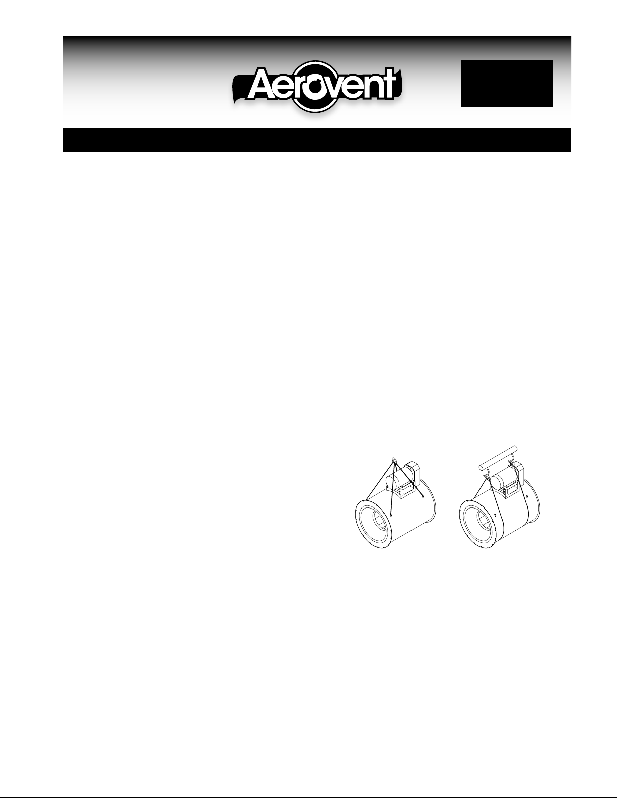
Units shipped completely assembled may be lifted
with slings and spreader bars. Use well-padded chains,
cables or nylon straps (see Figure 1). On most units,
lifting lugs are fashioned to protect the fan and fan
housing from damage. Never lift a fan by the inlet or
discharge flange, shafting or drives, wheel, motor or
motor base, or in any other manner that may bend or
distort parts.
If installation is to be delayed, store the unit in a
protected area. Protect the fan and motor bearings from
moisture and vibration (or shock loading). For extended
storage, wrap entire unit in plastic. Wrap loosely so air
may circulate around the fan and moisture does not
collect, or use a desiccant. Extended storage requires
monthly inspections. Check for corrosion or damage to
the unit and for debris within the fan. Rotate the fan
wheel a few revolutions. Stop the wheel in a position
other than the initial position. Grease the bearings every
month with a grease compatible with the grease supplied with the bearings.
Foundations and Supporting Structures
The AMX series can be mounted horizontally, vertically,
or at any angle if ordered accordingly. Mounting brackets
are available to accept both vibration isolating hangers
or pads. Typical mounting arrangements are shown in
Figures 2 through 8. Floor or wall mounted fans may be
installed on a flat, rigid foundation.
When mounting to concrete, anchor bolts should be
“L” or “T” shaped with sufficient length for nuts, washers, shims, and threads for draw-down. Each bolt should
be placed in a sleeve or pipe with diameter larger than
the bolt to allow for adjustment. When the mounting
surface and the surface of the fan base do not match,
shim level. Do not distort the fan when tightening the
anchor bolts.
A fan mounted to or within a structure should be
placed as close as possible to a rigid member such as
a wall or a column. The structure must be designed for
rotating equipment. Static design for strength is not sufficient to insure operation at low vibration levels. Supports
for suspended fans must be cross-braced to prevent
side-sway. Structural resonance should be at least 20%
from fan operating speed. Vibration isolators may help
block the transmission of vibration into a structure.
Any ducting should have independent support; do not
use the fan to support ducting. Flexible connections are
required whenever the fan is supported on vibration
isolators.
Figure 1.
Lifting With Lifting Lugs Lifting With Straps &
(Standard) Spreader Bar (Not Provided)
Fan Installation, Factory Assembled Units
Follow proper handling instructions as given earlier.
1. Move the fan to the final mounting position.
2. Remove skid, crates and packing materials carefully.
3. Attach vibration isolators (if used) to appropriate
mounting clips on fan. Locate fan in position using
lifting instructions above.
4. Carefully level unit using shims (on rigid mounted
fans) at mounting hole locations. Fans mounted with
vibration isolators may be leveled by adjusting the
hardware.
5. Continue with Operations Checklist.
©2009 Aerovent
Motor Maintenance
The three basic rules of motor maintenance are:
1. Keep the motor clean.
2. Keep the motor dry.
3. Keep the motor properly lubricated.
Blow dust off periodically (with low pressure air) to
prevent motor from overheating.
Some smaller motors are lubricated for life. Lubrication
requirements are normally attached to the motor. Use
the motor manufacturer’s recommendations for relubrication. If this information is not available, the following
schedule may be used. Motors less than 10 HP running
about eight hours a day in a clean environment should
be lubricated once every five years; motors 15 to 40
HP, every three years. For motors in dusty or dirty
environments or running 24 hours a day: divide the
service interval by 4. Do not over lubricate.
Drive Maintenance and Installation
V-belt drives need periodic inspection, retensioning, and
occasional belt replacement. When inspecting drives,
look for dirt buildup, burrs or obstructions that can
cause premature belt or drive replacement. If burrs are
found, use fine emery cloth or a stone to remove them.
Be careful that dust does not enter the bearings.
Check sheaves for wear. Excessive slippage of belts
on sheaves can cause wear and vibration. Replace worn
sheaves with new ones. Carefully align sheaves to avoid
premature sheave failure.
Inspect the belts for wear. If fraying or other wear is
observed to be mostly on one side of the belts, the
drives may be misaligned. Reinstall the drives according
to the following instructions:
1. Slip (do not pound) proper sheave onto corresponding
shaft. CAUTION: Placing fan sheave on motor can over-
speed wheel and cause structural failure.
2. Align sheaves with straightedge extended along
sheaves, just making contact in two places on outside perimeters of both sheaves.
3. Tighten sheave bolts (or setscrews if appropriate).
Table 1 can be used to determine the amount of
torque required.
4. Install a matched set of belts. Adjust the motor position to obtain slack, install, and tighten belts. Using
a pry bar will damage belts.
5. Tighten belts to proper belt tension. Ideal tension is
just enough so that the belts do not slip under peak
load. When using drive tensioning data supplied by
V-belt drive manufacturers, new belts can be tensioned
to a value 50% greater than for normal operation. This
will reduce retensioning requirements after break-in.
Recheck sheave alignment after tensioning.
6. After initial installation of belts, recheck belt tension
again after a few days. (New belts require a break-in
period of operation.)
7. When replacing belts, replace the entire set. After
initial replacement and tensioning, recheck belt tension after a few days. (New belts require a break-in
period of operation.) Never use belt dressing on any
belts.
8. Fans that have motors and drives mounted at the
factory are trim balanced prior to shipment. This is
not possible on units that are shipped without motors
and drives. The addition of drive components in the
field can create unbalance forces. Aerovent recommends final balancing of the unit after the drive
components are installed. Failure to do so may void
the warranty.
Motor Support Adjustment
Two different types of motor mounts, post and saddle,
are used on AMX Mixed Flow fans. Which mount to use
depends on the size of the fan and motor.
On the post type motor mount, the motor plate is
supported on four threaded rods. Belt tension is adjusted by loosening the four nuts on top of the motor plate
and raising the motor plate by adjusting the four nuts
underneath it. The top nuts should then be tightened to
hold the motor plate in place.
On the saddle type motor mount, the motor pivots
on one side and adjustment of belt tension is achieved
by loosening the nuts on top of the motor plate on the
other side, then raising the motor plate by adjusting the
nuts underneath the motor plate. The nuts on top of the
motor plate should again be tightened to hold the motor
plate in place. Several holes are provided on the pivot
side, and the pivot point can be raised for gross belt
adjustment. If this adjustment is made, however, the
motor plate should be as parallel as possible to the fan
centerplane. Care should be taken to maintain drive
alignment and proper belt tension.
Bearing Maintenance
Proper lubrication of the fan drive bearings helps assure
maximum bearing life. All fans are equipped with decals
indicating relubrication intervals for normal operating
Table 1. Tightening Torque (Ft.-Lbs.)
FASTENER TAPER BUSHINGS
SIZE BROWNING SPLIT QD
#10 — — — — — 5
1
1-8 250 645 900 — — —
1
Tolerance: +5%
For wheel setscrews use Grade 2 values.
The above torque values are for nonlubricated fasteners.
⁄4-20 5.5 8 12 7.9 7.5 9
5
⁄16-18 11 17 25 16 13 15
3
⁄8-16 22 30 45 29 24 30
7
⁄16-14 30 50 70 — — —
1
⁄2-13 55 75 110 70 — 60
9
⁄16-12 — — — — — 75
5
⁄8-11 100 150 220 — — 135
3
⁄4-10 170 270 380 — — —
7
⁄8-9 165 430 600 — — —
1
⁄4-7 500 1120 1500 — — —
GRADE 2 GRADE 5 GRADE 8
IN IRON IN ALUM. HUB FOR DRIVE
2
Aerovent IM-166
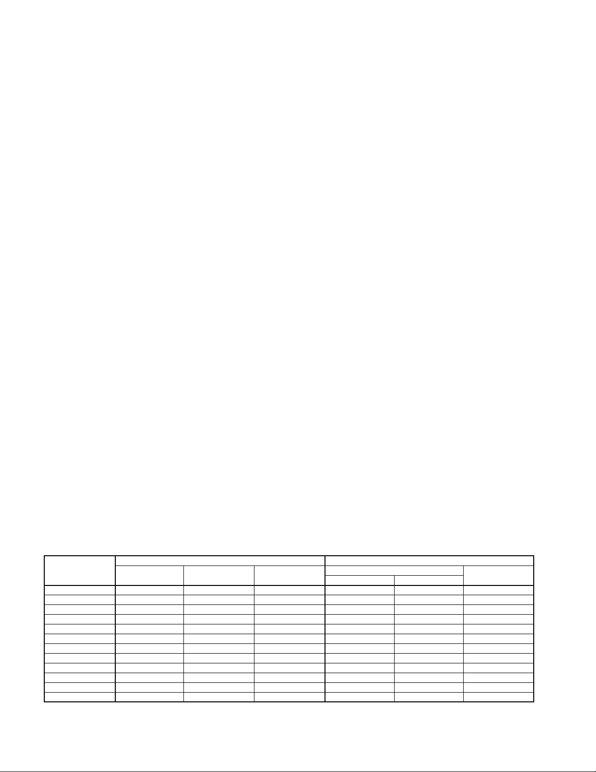
conditions. See Table 2 for typical lubrication data.
However, every installation is different and the frequency
of relubrication should be adjusted accordingly.
On high moisture applications, the lubrication frequency may need to be doubled or tripled to adequately protect the bearings. Double the relubrication frequency on fans with vertical shafts.
Observation of the conditions of the grease expelled
from the bearings at the time of relubrication is the best
guide as to whether regreasing intervals and amount of
grease added should be altered.
Greases are made with different bases. There are
synthetic base greases, lithium base, sodium base, etc.
Avoid mixing greases with different bases. They could
be incompatible and result in rapid deterioration or
breakdown of the grease. The lubrication sticker identifies a list of acceptable lubricants. All bearings are filled
with a lithium-based grease before leaving the factory.
When the fans are started, the bearings may discharge
excess grease through the seals for a short period of
time. Do not replace the initial discharge because leakage
will cease when the excess grease has worked out.
Sometimes the bearings have a tendency to run hotter
during this period. There is no reason for alarm unless
it lasts over 48 hours or gets very hot (over 200°F). When
relubricating, use a sufficient amount of grease to purge
the seals. Rotate bearings by hand during relubrication.
Wheel and Shaft Maintenance
Periodically inspect the shaft and wheel for dirt buildup,
corrosion, and signs of excess stress or fatigue. Clean
the components. If the wheel is removed for any reason,
make sure that it is securely attached to the shaft before
restarting the fan.
Structural Maintenance
All structural components or devices used to support or
attach the fan to a structure should be checked at
regular intervals. Vibration isolators, bolts, foundations,
etc., are all subject to failure from corrosion, erosion,
and other causes. Improper mounting can lead to poor
operation characteristics or fan fatigue and failure. Check
metallic components for corrosion, cracks, or other signs
of stress. Concrete should be checked to insure the
structural integrity of the foundation.
Operation Checklist
• Verify that proper safety precautions have been followed.
• Electrical power must be locked off.
Check fan mechanism components:
• Nuts, bolts, setscrews are tight.
• Mounting connections are properly made and tightened.
• Bearings are properly lubricated.
• Wheel, drives and fan surfaces are clean and tightened.
• Rotating assembly turns freely and does not rub.
• Drives on correct shafts, properly aligned, and properly tensioned.
Check fan electrical components:
• Motor is wired for proper supply voltage.
• Motor was properly sized for power of rotating
assembly.
• Motor is properly grounded.
• All leads are properly insulated.
Trial “bump”:
• Turn on power just long enough to start assembly
rotating.
• Check rotation for agreement with rotation arrow.
• Listen for any unusual noise.
Run unit up to speed:
• Bearing temperatures are acceptable (<200°F) after
one to two hours of operation.
• Check for excess levels of vibration. Filter in readings should be 0.15 inches per second or less.
After one week of operation:
• Check all nuts, bolts and setscrews and tighten if
necessary.
• Re-adjust drive tension if necessary.
Table 2. Relubricating Schedule (Months) — Ball Bearing Pillow Blocks
SPEED (RPM)
SHAFT DIA.
1
⁄2"– 111⁄16" 6 6 5 3 3 2 2 2 1
15
⁄16" – 27⁄16" 6 5 4 2 2 1 1 1 1
1
11
⁄16" – 215⁄16" 5 4 3 2 1 1 1 — —
2
7
⁄16" – 315⁄16" 4 3 2 1 1 1 — — —
3
500 1000 1500 2000 2500 3000 3500 4000 4500
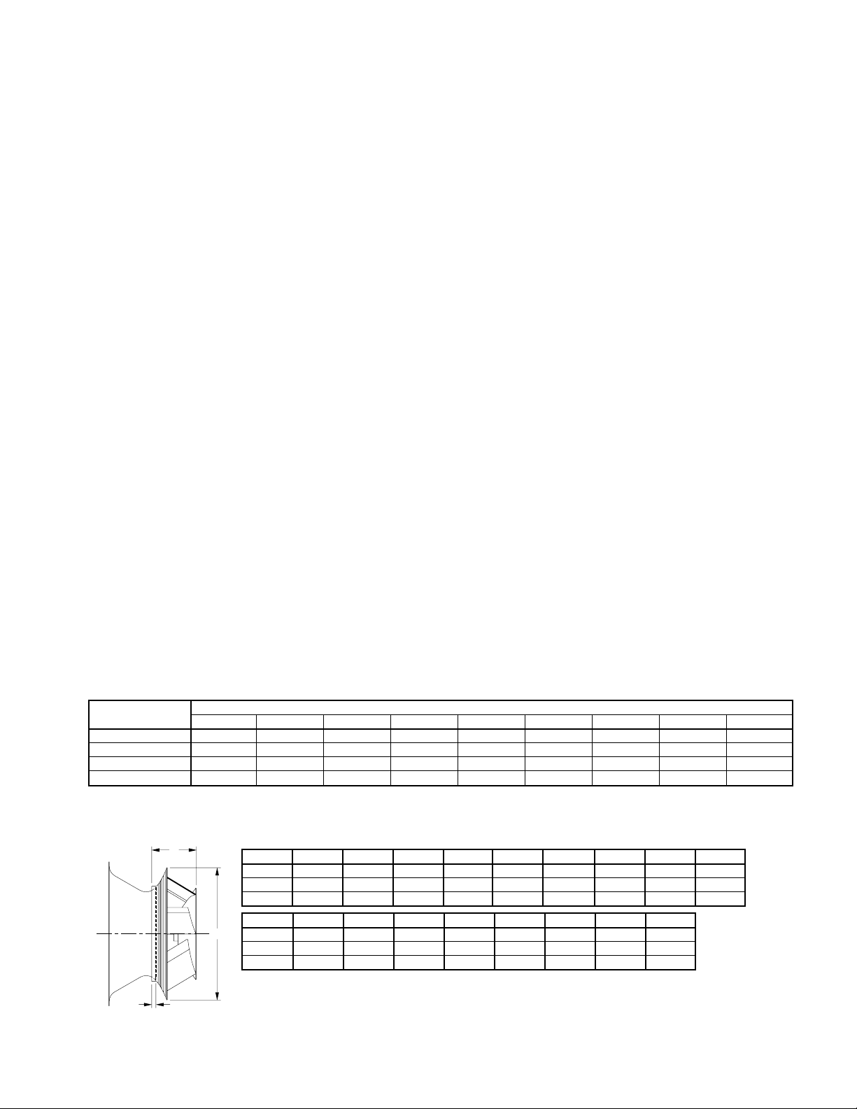
Table 3. AMX Wheel-Funnel Overlap
C
B
SIZE 150 165 182 200 222 245 270 300 330
A 18.25 20.00 22.25 24.50 27.00 30.00 33.00 36.50 40.25
B 0.56 0.63 0.69 0.75 0.88 0.97 1.06 0.94 1.03
C 6.19 6.75 7.56 8.31 9.13 10.19 11.19 12.38 13.63
SIZE 365 402 445 490 542 600 660 730
A
A 44.50 49.00 54.25 60.00 66.00 73.00 80.75 89.00
B 1.13 1.25 1.38 1.56 1.69 1.88 2.09 2.28
C 15.13 16.63 18.38 20.25 22.31 24.63 27.25 30.00
Note: Use “B” dimension for positioning wheel.
Aerovent IM-166
3
 Loading...