

Aerovent IM-165 User Manual
IM-165
April 2005
General Installation, Operation and Maintenance Instructions For Aerovent Products
Centaxial Fans
Direct and Belt Driven
Aerovent Centaxial fans are designed for continuous duty in
air-moving systems handling clean air. As a general rule, these
fans are designed to be installed in any position. However,
larger fans and fans with high horsepower loading may not be
suitable for vertical installation. It is advisable to check with
the factory to determine if vertical installation is satisfactory.
Upon receipt of equipment, inspect the fan and its accessories for possible damage in shipment. Make certain the
wheel rotates without binding. Never lift the Centaxial fan by
its motor, fan wheel or shaft. Lifting eyes are provided for this
purpose.
If the unit is not to be put in operation for a period of
time and is to be stored, the following precautions should be
observed:
1. Select a clean, dry location to prevent rust.
2. For outside storage, protect against the elements by covering the inlet and outlet of the fan.
3. Make certain bearings are filled with grease. (See General
Installation and Maintenance Manual IM-100 for lubrication procedure.)
4. Keep motors dry and clean.
5. Periodically inspect unit to see if conditions are present
which could cause damage.
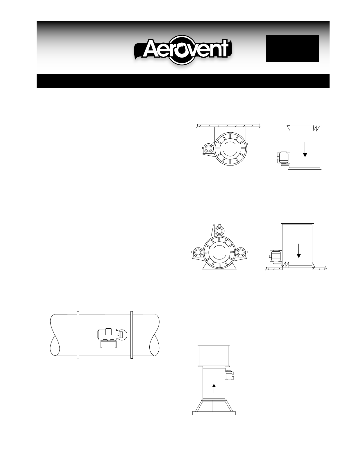
Discharge
End
Horizontal - Ceiling Vertical - Ceiling
When suspending the fan from overhead with rods or other
arrangements, support of the load should be accomplished
by means of diagonal bracing to prevent side sway. Welded
construction of the support should be used rather than bolted
due to the loosening of bolts by vibration.
Discharge
End
Horizontal - Floor Vertical - Floor
AIRFLOW
AIRFLOW
Mounting Arrangements
Duct Mounted
The mounting flanges on the Centaxial fan are capable of
supporting the fan in ductwork and are of the same size at
the inlet and outlet for easy installation in a straight-line duct
system. However, the ducts must be structurally sufficient to
support the load. The following bolt sizes are required when
mounting fan to duct: 3∕8" on sizes 12 through 44; 1∕2" on sizes
49 and larger.
©2005 Aerovent
A concrete foundation should be provided for mounting the
centaxial fan on the floor. The size of the fan will determine
the size of the foundation. The concrete base should extend
approximately 6" beyond the outline of the fan and should
have a weight capable of supporting the unit. Anchor bolts
should be provided for bolting to the foundation.
Roof Ventilator
Where the centaxial fan is to be
HEAD
SECTION
mounted as part of a roof ventilator assembly, caulking must be done
after assembly between flanges of
FAN
SECTION
the head section and fan section and
base. Guy wire bracing is required
on all large size units to prevent side
sway.
See IM 120 for further instruc-
BASE
tions regarding roof ventilator installation.
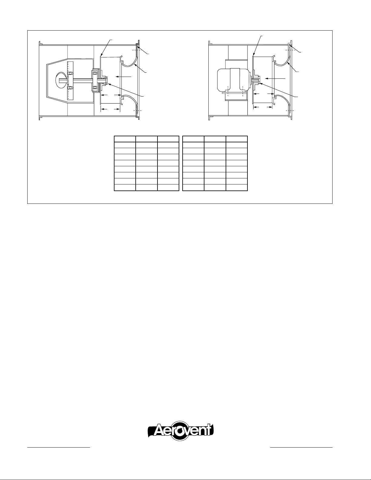
All dimensions in inches.
Wheel
Back Plate
A
W
Guide Vanes
Wheel
A
W
Wheel
Back Plate
Airflow
Bar Ring
Inlet Cone
Taper Lock
Bushing
Guide
Vanes
Belt Driven Direct Drive
SIZE A W*
12 4
14 57⁄32 51⁄32
16 527⁄32 521⁄32
18 621⁄32 63/8
20 73/8 71⁄16
22 81⁄4 715⁄16
25 95⁄16 815⁄16
28 1017⁄32 101⁄16
5
⁄8 57⁄16
*100% wheel width
SIZE A W*
32 11
35 135⁄16 123/4
39 1427⁄32 143/16
44 169⁄16 157/8
49 189⁄16 1723⁄32
55 207/8 1927⁄32
63 243/4 2211⁄16
71 2615⁄32 251⁄2
27
⁄32 1111⁄32
“A” dimension (inlet cone to wheel back plate) must be held. This dimension is
critical to fan performance. “A” dimension shown is based on 100% wheel width
and must be adjusted if wheel furnished is other than 100% full width.
Airflow
Bar Ring
Inlet Cone
Taper Lock
Bushing
General Maintenance
A regular fan maintenance schedule should be established to
include the following:
1. Fan Wheel: The fan wheel in a centaxial fan must be kept
reasonably clean if it is to perform properly. Where dirt
build-up is slight, very little unbalance can result. Air heavily laden with grease and dirt will deposit a great deal on
impeller blades. Conditions should be observed and cleaning performed as required for smooth fan operation and,
in the case of grease, removal of this type of fire hazard.
One problem that often develops is the unbalance
which occurs when particles of dirt and grease are thrown
from the blades. This unbalance condition will naturally
cause excessive wear and noise. If the wheel shows excessive wear, it should be replaced.
Cleaning of the wheel should be accomplished, if pos-
sible, without removing it from the shaft. If the fan is
furnished with an access door, the wheel can be cleaned
through this opening. If no door is supplied, then the inlet
cone must be removed to expose the wheel. If for some
reason the wheel is removed from the shaft, take note
of the “A” dimension called out in the chart above. This
dimension must be held if proper performance is to be
maintained.
2. V-Belt Drive: Check V-belt drive for proper alignment
and tension. (See General Installation and Maintenance
Manual IM-100.)
3. Fan Bearings: Lubricate the bearings as detailed in
the ball bearing lubrication instructions in the General
Installation and Maintenance Manual (IM-100).
4. Screws and Bolts: Check tightness of all screws and
bolts throughout the assembly.
®
AEROVENT | WWW.AEROVENT.COM
5959 Trenton Lane N | Minneapolis, MN 55442 | Phone: 763-551-7500 | Fax: 763-551-7501
1.5MSS05/10
 Loading...