

Aerovent IM-160 User Manual
AIRFLOW
GUIDE
VANES
OPTIONAL WHEEL
INSPECTION SECTION
ACCESS DOOR
AIRFLOW
GUIDE
VANES
OPTIONAL WHEEL
INSPECTION SECTION
ACCESS DOOR
®
IM-160
March 2011
General Installation, Operation and Maintenance Instructions For Aerovent Products
Vaneaxial Fans
Available Vaneaxial Fan Designs
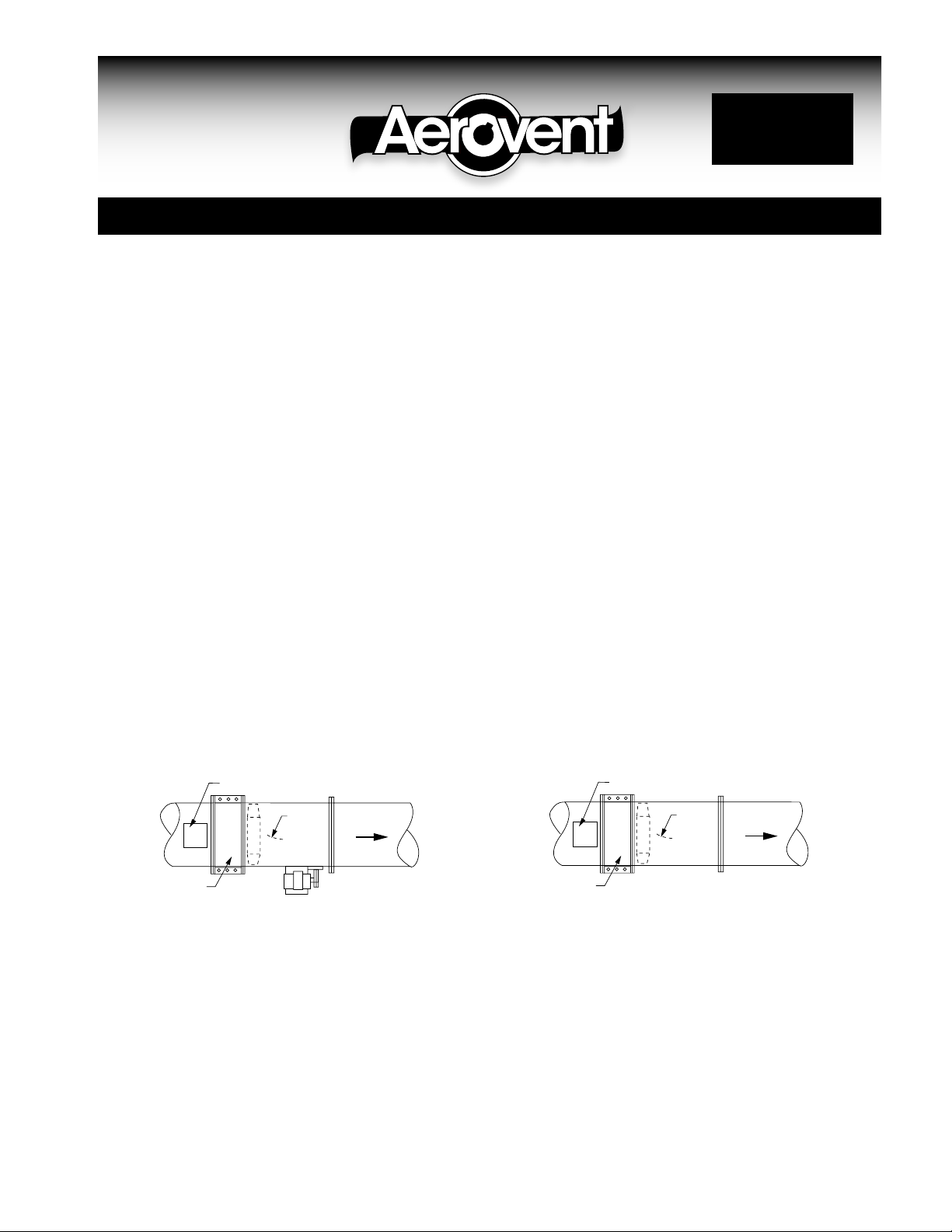
Belt Driven – Type B and P
The Type B and P belt driven vaneaxial fan designs
incorporate internal guide vanes welded around the
inner shell bearing support. A wheel inspection section to facilitate cleaning the cast solid aluminum propeller can be provided as an option. If this section is
not furnished it is necessary to field install an access
door in the duct next to the inlet or to remove the
fan from the duct system for cleaning of the propeller
and guide vanes. For high temperature or corrosive
applications, the Type B can be reconfigured with
an external guide vane section similar to the Type T
shown below.
Direct Drive – Type B and P
The Type B and P direct drive vaneaxial fan designs
incorporate internal guide vanes welded around a
circular bulkhead/motor base plate assembly. A wheel
inspection section to facilitate cleaning the cast solid
aluminum propeller can be provided as an option. If
this section is not provided it is necessary to field
install an access door in the duct next to the fan
inlet or to remove the fan from the duct system for
cleaning of the propeller and guide vanes.
Belt Driven – Type W & J
The Type W belt driven vaneaxial fan design incorporates internal guide vanes welded around the inner
shell bearing support. For Type W, a wheel inspection section to facilitate cleaning the adjustable pitch
aluminum propeller can be provided as an option. If
this section is not furnished it is necessary to field
install an access door in the duct next to the fan
inlet or to remove the fan from the duct system for
cleaning of the propeller and guide vanes. For Type
J, a propeller access door is provided as standard.
Direct Drive – Type W & J
The Type W direct drive vaneaxial fan design incorporates internal guide vanes welded around the circular
bulkhead/motor base plate assembly. For Type W,
a wheel inspection section to facilitate cleaning the
adjustable pitch aluminum propeller can be provided
as an option. If this section is not furnished it is
necessary to field install an access door in the duct
next to the fan inlet or to remove the fan from the
duct system for cleaning of the propeller and guide
vanes. For Type J, a propeller access door is provided as standard.
Type B, W, J & P Belt Driven Vaneaxial Fan
Belt Driven – Type S
The Type S belt driven vaneaxial fan design incorporates internal guide vanes welded around the inner
shell bearing support. An access door over the wheel
area can facilitate inspection of the welded steel
propeller and can be provided as an option. If wheel
cleaning capability is desired, it is necessary to field
install an access door in the duct next to the inlet or
to remove the fan from the duct system for cleaning
of the propeller and guide vanes.
©20011 Aerovent
Type B, W, J & P Direct Drive Vaneaxial Fan
SPINNER
FACTORY ADJUSTED
BLADES
CAPSCREW (3 REQ'D.)
SPINNER
BUSHING
SETSCREW
(7 REQ'D.)
HUB
BLADE
(7 REQ'D.)
FAN
ACCESS DOOR
(OPTIONAL)
VANE
SECTION
AIRFLOW
Belt Driven – Type T
The guide vanes are built into a removable section
of duct adjacent to the propeller and can be taken
completely out for cleaning without disturbing the fan.
Removing the vane section also provides access to
the cast solid aluminum propeller. The construction of
this fan lends itself to high temperature or corrosive
applications. As an alternative, an optional access
door can be provided in the fan housing for inspection and cleaning of the propeller.
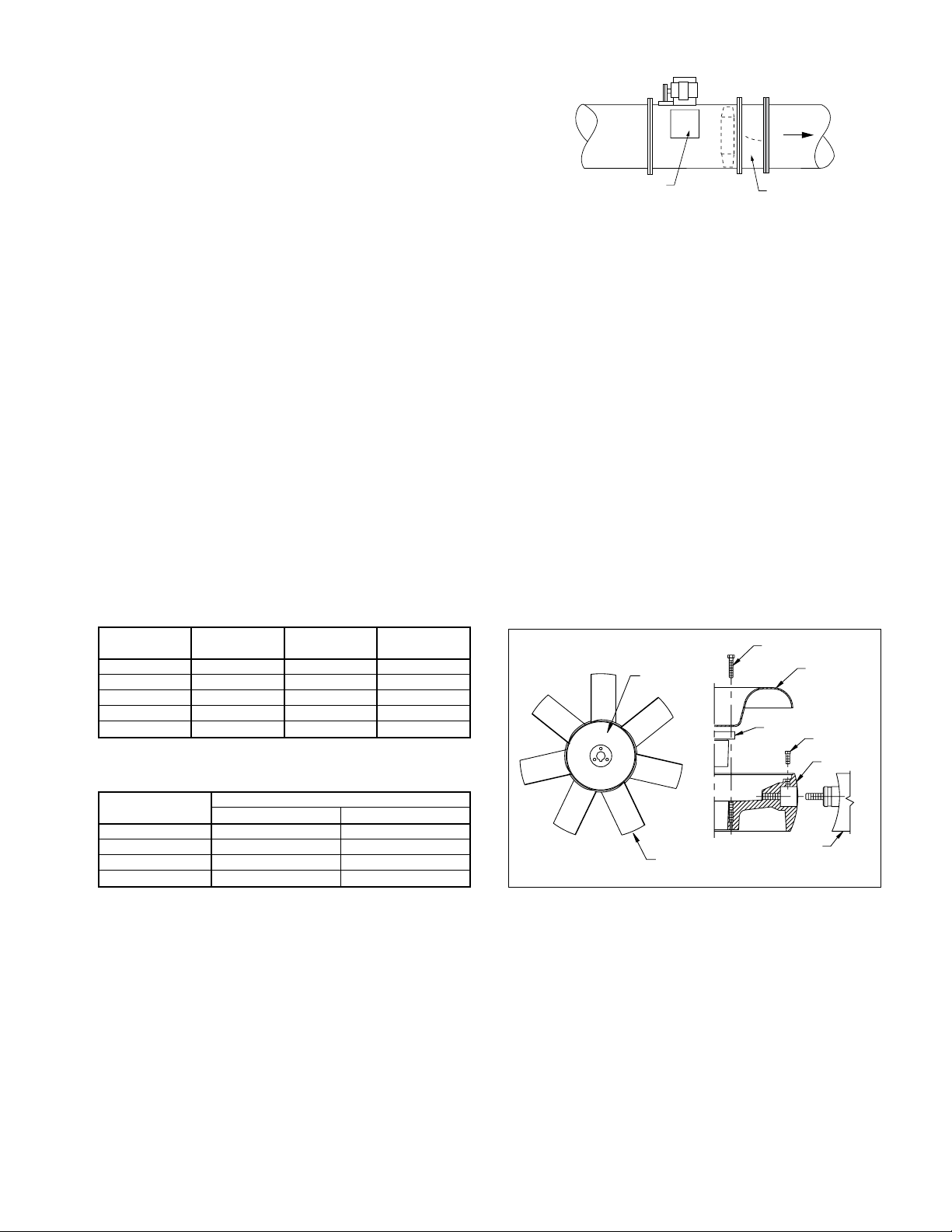
Type W - Adjustable Pitch Wheel
Type T Belt Driven & Type B High Temperature
The blade angle of the adjustable pitch Type W vaneaxial wheel has been set at the factory to deliver a
particular performance. However, the performance of
the fan can be changed by adjusting the blade to a
different angle, either higher or lower, depending on
the volume of air required. Blades may be adjusted
for low angles without concern of overloading motors.
When adjusting to higher angle settings, check motor
current to be sure the motor is not overloaded. Keep
motor current within nameplate and service factor
ratings. See Catalog 456 for Type W vaneaxial fan
performance data.
Bushing Bolt Torque Values
BUSHING
NO. (IN.) FT. LBS.
H
P-1
P-2
Q-2
R-2
DIAMETER
LENGTH TORQUE
1
⁄4-20 11⁄4 7
5
⁄16-18 11⁄2 13
5
⁄16-18 13⁄4 13
3
⁄8-16 21⁄2 24
3
⁄8-16 3 24
1
⁄2
Setscrew Torque Values
SETSCREW TORQUE (FT.-LB.)
SIZE SOCKET HEAD SQUARE HEAD
5/16 14 18
3/8 16 24
1/2 34 45
5/8 64 85
The blades are held in place by a high strength
specially designed steel bolt cast into the blade and
threaded into the hub. It is locked by one setscrew.
There is a scale on the hub which indicates the position in degrees. An index mark needs to be made on
the blade before adjusting.
To change the angle, simply loosen the setscrew
with an Allen wrench, adjust the index mark on the
blade to the proper angle setting on the scale on
the hub and tighten. The angle cannot be thrown off
once the locking setscrew is tightened. When increasing the angle, turn the propeller by hand to check tip
clearance before startup.
W7 Adjustable Pitch Wheel
2 Aerovent IM-160
 Loading...