

Aerovent IM-155 User Manual
®
IM-155
June 1997
General Installation, Operation and Maintenance Instructions For Aerovent Products
Two-Way and Three-Way Heat Saver/Ventilator
Heat saver ventilators are designed to recirculate warm air
from the ceiling to the work area or to exhaust air to the outside. Three-way heat savers (RREH) can also draw fresh air in
from the outside and blow it down into the work area.
Modulating dampers in the unit temper the air to the desired
temperature setting.
Heat saver ventilators are designed to be installed through
a prefab or an existing roof curb and rest on the unit’s curb
base section. Mount the curb base section onto the roof curb
and secure the stack cap (RRES) or hooded inlet (RREH) to
the fan section. Extensions of the fan section are available to
provide clearance of roof and structural members.
Note: The fan must be allowed to stop before the motor
rotation is reversed. Do not switch any unit from exhaust to
recirculate or supply without allowing the fan blades to stop
rotating.
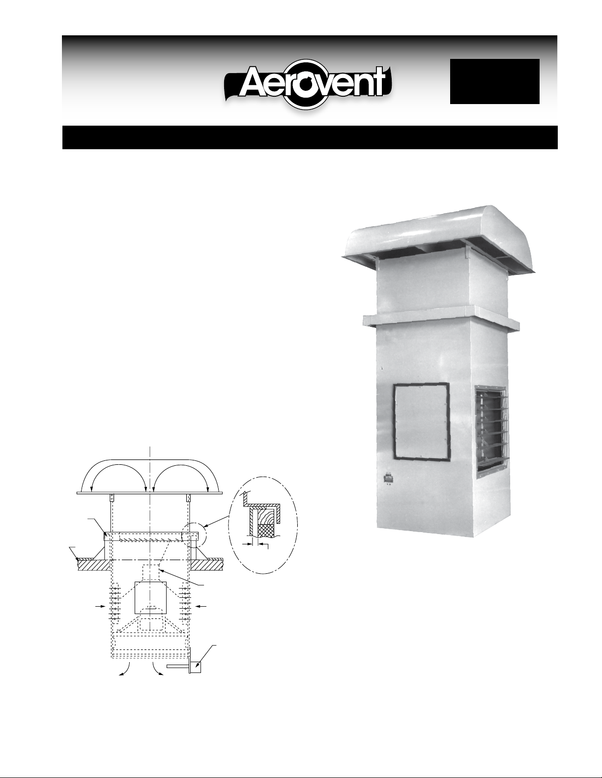
of Three-Way Heat Saver
EXHAUST EXHAUSTSUPPLY
CURB
BASE
SECTION
ROOF
AIRFLOW
Suggested Mounting
FAN SECTION
DAMPER
MOTOR
AIRFLOW
DISCHARGE
SENSOR
TEMPERED
AIR – WINTER
11/4"
Clearance
Discharge Sensor Mounting
The discharge sensor is mounted on the bottom edge of the
unit so as to protrude into the tempered airstream. The temperature reading is taken at the bottom of the unit, not at the
floor level. The temperature selector is located in the remote
control station.
©2000 Aerovent
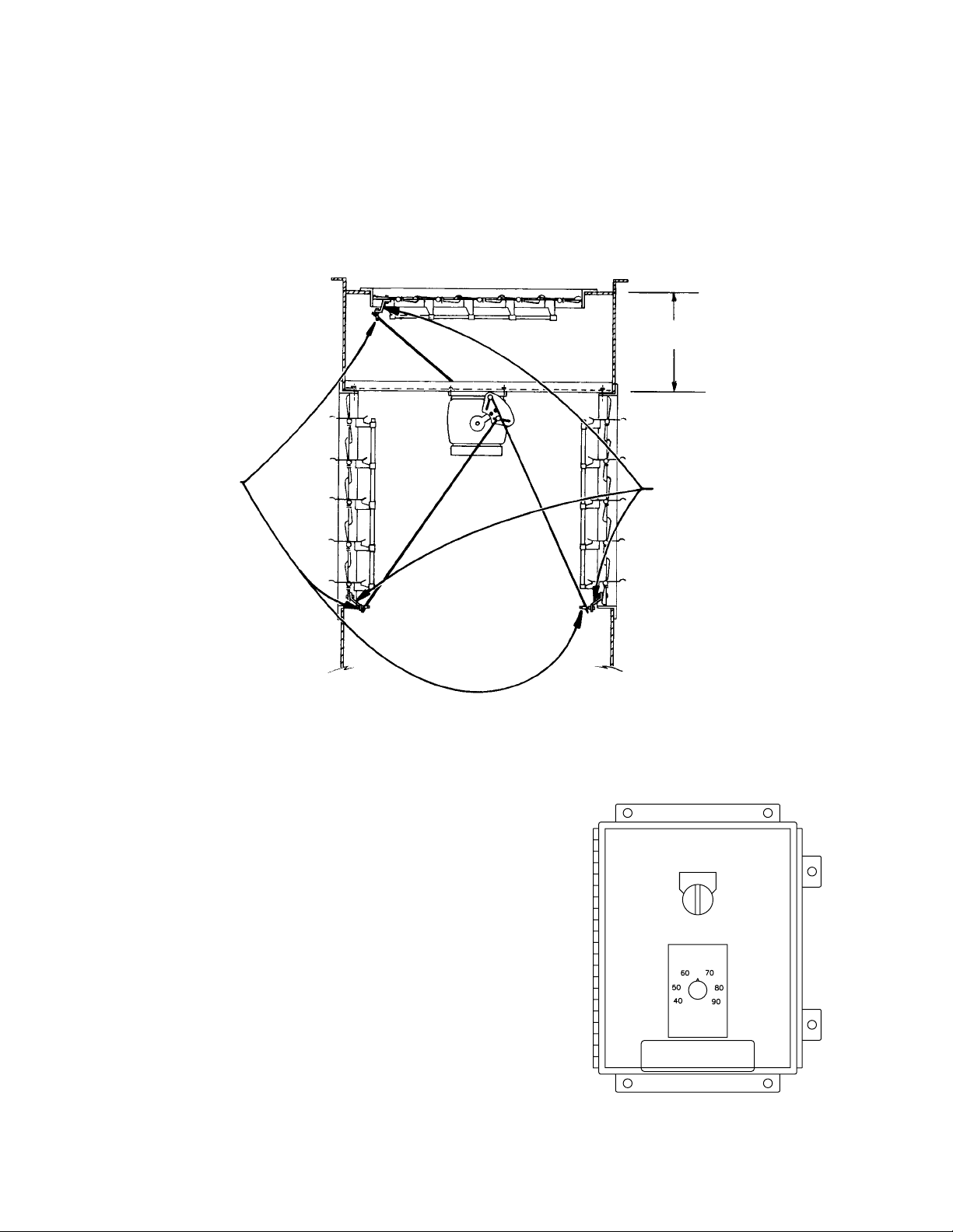
Three-Way Motor Actuated Dampers
Three-Way Heat Savers utilize three dampers, two normally open dampers mounted vertically on opposite sides for recirculation
and one normally closed damper mounted horizontally in the top of the unit just below the fresh air intake/exhaust head. The
three dampers are connected to one modulating motor. For recirculation, they are positioned by the discharge temperature control
to recirculate all or part of the air and introduce outside air to satisfy the desired temperature. For exhaust, the damper motor is
driven fully open, closing the side dampers and opening the top damper. The damper actuating rods are left unconnected on the
side recirculating dampers to facilitate shipping and easy installation. They must be reconnected to the dampers prior to start-up.
No adjustment is necessary. The damper in the head is normally closed and the recirculating dampers are normally open when the
actuating rods are connected.
16"
(3) Ball Joints
Remote Control Station Installation
The remote control station should be mounted approximately
5 feet above the floor on a stationary vertical surface. The
dampers should be checked for proper operation after all of
the electrical connections have been made. The recirculation
dampers will be closed and the damper in the head will be in
the full open position in the exhaust mode. In the supply
mode, the dampers will modulate by adjusting the temperature
selector. The dampers should operate freely without binding.
The control station will have a temperature selector and an
on/off switch.
(3) Blade Shutter Linkage
 Loading...