

Aerovent IM-140 User Manual

IM-140
June 1997
General Installation, Operation and Maintenance Instructions For Aerovent Products
Centrifugal Fans
Bearings
Before the unit is put into operation, tighten bearing collar
setscrews and bearing anchor bolts. Rotate shaft to check
alignment.
All grease lubricated bearings are completely filled with
grease prior to shipment from the factory. This prevents the
condensation of moisture in the pillow block during shipment
and before the unit is installed.
The bearings will discharge excess grease through the seals
for a short period of time after start-up. Do not replace this initial discharge, because leakage will cease after the excess grease
has been purged from the bearings. Also, the purging of the
excess grease will cause the bearing to heat up, but the heat will
dissipate after the purging.
Observation of the amount of grease expelled from the
bearing at the time of relubrication is the best guide as to
whether the regreasing intervals and amount added should be
altered. When regreasing, use lubrication instructions for fan
ball bearings as outlined in IM-100 which is included with shipment. Avoid mixing different types of grease. Bearings should
be flushed and refilled with fresh grease at approximately oneyear intervals. DO NOT OVER LUBRICATE.
Couplings
Arrangement 7 and 8 direct drive fans, which are shipped completely assembled with motor and coupling mounted, should be
checked for correct coupling alignment before putting the unit
into operation. Also check lubricant, following manufacturer’s
recommendations for type and amount of lubricant used.
Foundations
A rigid, level foundation is essential for smooth and quiet
operation, good performance, and low maintenance expenses.
Inadequate foundations may lead to excessive vibration in wellbalanced fans, resulting in possible premature failure.
Particular attention must be given to ensure a solid support
for the rotating assembly, particularly in the area of the bearing
and motor supports.
V-Belt Drive
On belt-driven units, position and anchor the motor slide base
firmly to the foundation or bearing base. Mount the motor on
the slide base and move the motor to the position closest to the
the fan. The V-belt drive should be mounted as follows:
1. Remove dirt and corrosion from fan and motor shafts.
2. Coat bores of sheaves with grease or oil and mount sheaves
on the shafts. Do not force the sheaves on the shafts by hammering as this will damage the fan and motor bearings.
3. Install the belts. Belts should be worked carefully over the
grooves of each sheave until they are properly in place. Belts
should never be forced on with a screwdriver or similar tool
as this will break the cords in the belts. After the belts have
been installed, adjust the sheaves so that both shafts are at
right angles to the belts. See IM-101 for alignment procedure. Once proper alignment is assured, tighten sheaves in
place.
4. Take up slack by adjusting the motor slide base. Proper belt
tension is important. If belts are too tight, undue wear on fan
and motor bearings will result. Insufficient tension shortens
belt life and may cause vibration. Use drive manufacturer’s
recommendations for correct belt tension.
5. IMPORTANT! BEFORE PUTTING THE UNIT
INTO CONTINUOUS OPERATION, INSTALL BELT
GUARD.
6. After several days of operation, check belt tension and
sheave alignment.
Safety Practices
1. Do not operate fan at speeds in excess of factory specified
limits for each construction class.
2. Where applicable, provide inlet or outlet screens to prevent
objects from entering the fan.
3. Provide adequate guards over rotating parts, belt guard, shaft
guards, and coupling guards.
4. Locate a disconnect switch with padlock at fan for maintenance personnel. Also provide means for locking out primary power where possible.
5. Provide vibration limiting switches to detect sudden change
in fan operation, particularly on critical applications such
as high speed, high temperature, or in erosive or corrosive
atmospheres.
See AMCA Publication 410, Revision 2, for additional safety
practices.
©2005 Aerovent
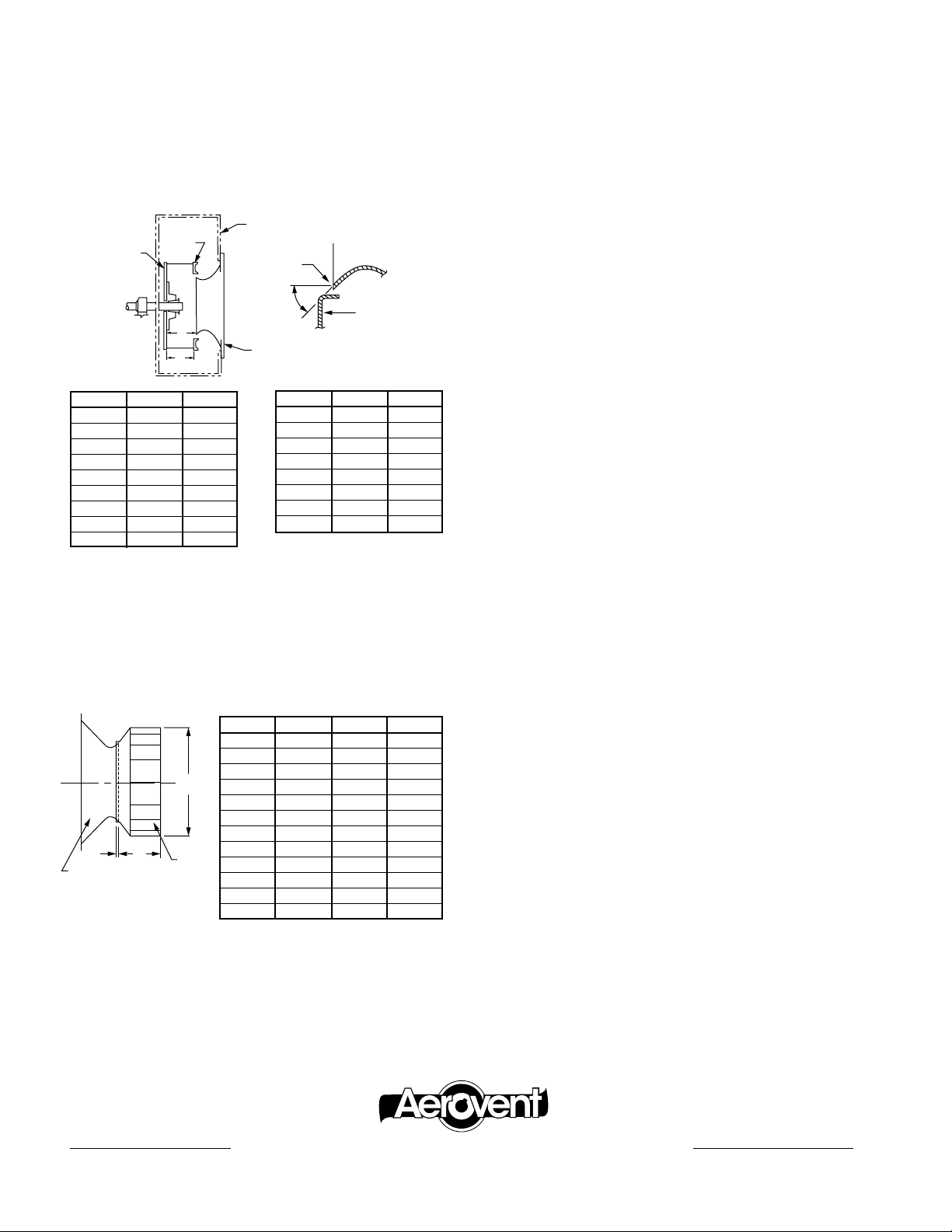
Wheel Clearance
DIA.
Adjust clearance by moving the wheel axially on the shaft. The
following table indicates the correct measurements for positioning the BI and BIA wheels. Proper positioning is important in
attaining correct fan performance, particularly on the BI and
BIA wheels.
Type BW, OW, PB & HPB
These radial blade wheels do not require precise positioning
to attain the correct performance. The important thing is to
centrally locate these wheels axially within the housing to ensure
adequate running clearance and to maintain concentricity with
the fan inlet.
Type BI & BIA (SWSI Units)
Housing
Front
Wheel
Back Plate
SIZE A W*
12 4
14 59/32 51/32
16 529/32 521/32
18 623/32 63/8
20 77/16 71/16
22 85/16 715/16
25 95/16 815/16
28 1017/32 101/16
32 1127/32 1111/32
Plate
A
W
11
/16 47/16
Wheel/Cone
Geometry
45°
Inlet
Cone
SIZE A W*
35 13
39 1427/32 143/16
44 169/16 157/8
49 189/16 1723/32
55 207/8 1927/32
63 233/4 2211/16
71 2619/32 251/2
79 295/8 2811/32
*100% Wheel Width
Inlet
Cone
Wheel Front
Plate
15
/16 123/4
“A” dimension (inside edge of inlet cone to inside face of
wheel backplate) must be held. This dimension is critical to fan
performance. “A” dimension shown is based on 100% wheel
width “W” and must be adjusted if wheel furnished is other
than 100% full width.
Type BIUB
SIZE A B C
12 12.25 0.32 4.28
13 13.50 0.34 4.84
15 15.00 0.38 5.38
A
16 16.50 0.44 5.81
18 18.25 0.56 6.44
20 20.00 0.63 7.00
22 22.25 0.69 7.84
B
Inlet Cone
C
24 24.50 0.75 8.63
Wheel
27 27.00 0.88 9.47
30 30.00 0.97 10.56
33 33.00 1.06 11.63
36 36.50 1.10 13.03
Type AW
These wheels require a special inlet on the housing which must
extend into the wheel inlet flange to perform properly. Other
than maintaining a minimum 1∕4" overlap, adequate running
clearance and concentricity are all that is required.
Type FC
The forward curve blower employs a shallow venturi in the
housing to guide the air into the wheel. The depth of this venturi is approximately one-tenth the wheel diameter. Clearance
between the wheel and venturi should be the smallest allowable
and still maintain normal running clearance. This axial separation is approximately
1
∕4" and should be measured at four points
approximately 90° apart.
Maintenance
Regular and systematic inspection of all fan parts is the key to
good fan maintenance. Frequency of inspection is determined
by the severity of the application and local conditions. Once a
maintenance schedule is established, it should be strictly followed. Regular fan maintenance should include the following:
1. Check fan wheel for any build-up of foreign material or
excessive wear from abrasion. Both can cause vibration
which creates a serious safety hazard. Any build-up of foreign material should be removed. If the wheel shows excessive wear, replace it immediately.
2. On belt driven units, check V-belt drive for proper alignment
and tension. If belts show wear, they should be replaced with
a matched set of belts. If unit is direct driven, check coupling
alignment.
3. Lubricate the bearings (see bearing section for lubrication
specifications). On direct drive units, lubricate the coupling
(see coupling section).
4. Lubricate shaft seal with the same grease as used on the fan
bearings. IMPORTANT: The operating life of the shaft seal
is dependent upon the amount and frequency of lubrication.
Insufficient grease in the shaft seal may result in damage to
the seal and reduced sealing efficiency.
5. A final check on the tightness of all setscrews and bolts
completes the maintenance routine.
®
3MSE09/09
AEROVENT | WWW.AEROVENT.COM
5959 Trenton Lane N | Minneapolis, MN 55442 | Phone: 763-551-7500 | Fax: 763-551-7501
 Loading...