

Aerovent IM-105 User Manual
®
IM-105
June 1997
General Installation, Operation and Maintenance Instructions For Aerovent Products
Shutter Types and Construction
Automatic
Automatic shutters are constructed with galvanized steel
frames and drilled for ease of installation. Aluminum feltedged blades open from fan pressure and close automatically
when fan is off. All aluminum construction is available as an
option.
Motor-Operated, End-Pivoted
Used for exhaust only. Constructed of galvanized steel frames
and aluminum felt-edged blades. Flanges are drilled for ease of
installation. Motor-operated units are furnished with electric
actuators. These actuators are not equipped with end switches.
All-aluminum construction is available as an option.
Motor-Operated, Center-Pivoted
Can be used in either supply or exhaust applications.
Constructed of galvanized steel frames and blades with stainless steel jamb seals. Blades are held in place with oil-impregnated bronze bushings. Motor-operated units are supplied
with electric actuators that are furnished with end switches.
ManuallyOperated
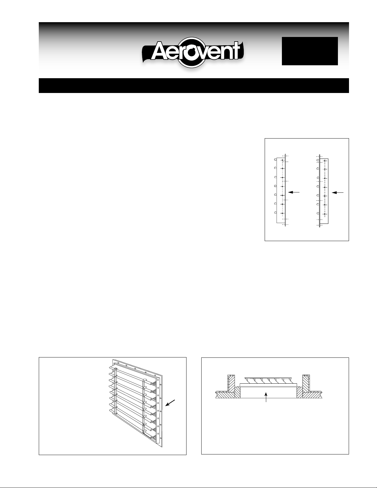
AEROVENT SHUTTER
FLANGE ARRANGEMENT
Manually-operated
shutters are of the
same rugged construction as the automatic
shutter. This shutter is
supplied with a six-foot
AIRFLOW
AIRFLOW
pull chain connected
through a pulley on the
inside of the shutter.
Spring arrangement
holds louver tightly
closed when unit is not
in use. All aluminum
STANDARD
FLANGE
REVERSE
FLANGE
construction is available as an option.
Extra Heavy-Duty
Extra heavy-duty shutters are recommended where discharge
velocity exceeds 2400 FPM or where velocity is low and excessive fluttering action is a concern. All extra heavy-duty shutters
have 16-gauge aluminum blades. Can be provided as automatic, manual or motorized operation.
AUTOMATIC TYPE:
Designed for horizontal
airflow — gravity close.
Optional bird screen
shown.
Typical Shutter Installations
Airflow
CEILING TYPE: Designed for vertical airflow.
Auto-matic gravity close. Exhaust only
©1997 Aerovent
Airflow
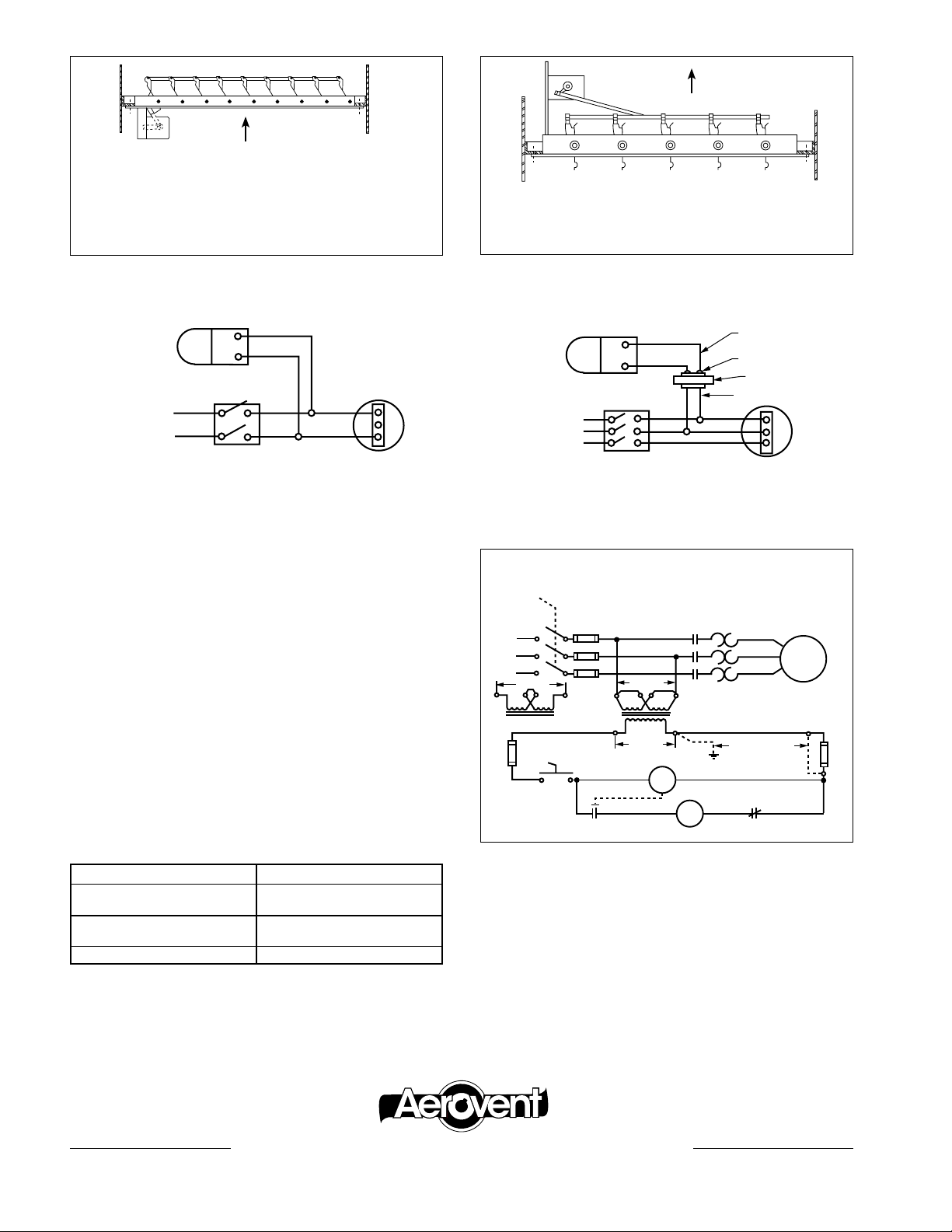
Airflow
MOTOR-OPERATED, END-PIVOT:
For vertical or horizontal airflow. Exhaust only.
Shutter Motor
Airflow
MOTOR-OPERATED, CENTER-PIVOT:
Designed for supply and exhaust.
Damper
Motor
115V
Fan
Motor
115V
Supply
Fan Switch
End Switch For Motor Operated Shutter
Motor operated shutters used in air-handling systems should
be wired to allow the shutter to open before the fan is started.
A shutter end switch should be mounted in the fan starter
circuit. The shutter end switch may be one of two types:
1. LEVER OR LINKAGE ACTUATED: Allen Bradley
802TAW1 or equal. Mount switch to be actuated by shutter
linkage or shutter leaf when shutter is approximately 80%
to 90% open.
2. MOTOR MOUNTED AUXILIARY SWITCH: Switch
mounts on side of motor opposite shutter linkage and is
actuated by shaft. Set so cam actuates switch when shutter
is 80% to 90% open.
The following end switches can be used on various motors.
A. Control Transformer (115V Secondary)
B. On-Off Selector Switch
C. Shutter Motor (115V)
Damper
Motor
115V
230V or 460V
Supply
Disconnect
Switch
480V
3A
OffOn
B
Fan Switch
115 Volt Control Circuit
240V
A
115V
C
D
E
Secondary
Low Volt Terminal
Transformer
Primary
To Be Grounded
By User If
Conditions Permit
F-Typ.
Fan
Motor
Fan
Motor
3A
END SWITCH MOTOR
Allen-Bradley 802TAW1
(Not Furnished)
Honeywell M4185 (Dual Shaft)
Built In Barber-Colman MA418-500
Honeywell M4182 (Single Shaft)
Built In
Multi-Products 2027
D. Shutter End Switch
E. Holding Coil — Fan Starter (115V)
F. Thermal Overload Contactors
All shutter motors operated on 115 volts.
®
AEROVENT | WWW.AEROVENT.COM
5959 Trenton Lane N | Minneapolis, MN 55442 | Phone: 763-551-7500 | Fax: 763-551-7501
 Loading...