

Aerovent IM-101 User Manual
IM-101
June 1997
General Installation, Operation and Maintenance Instructions For Aerovent Products
Alignment
V-Belt Drive
Proper alignment and balance of the V-belt is as important as
a well-balanced impeller. To insure smooth fan operation, the
following should be checked:
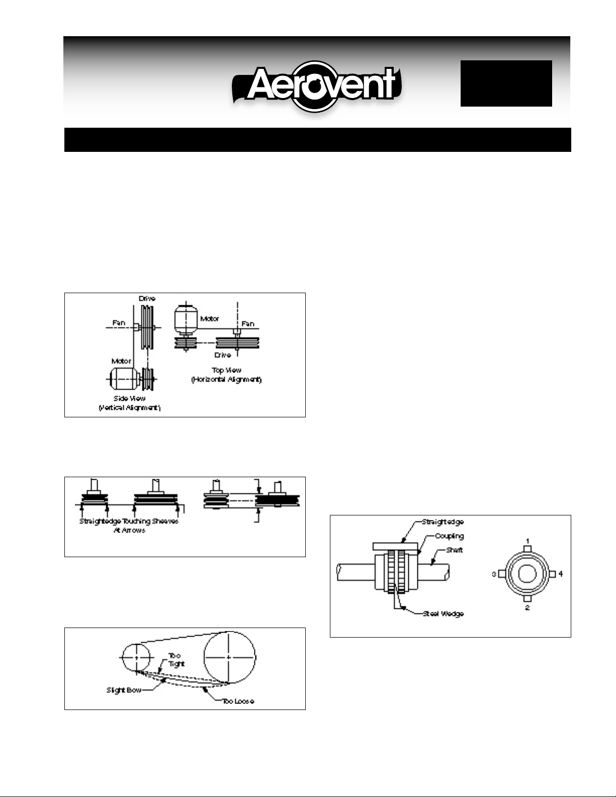
1. Fan and motor sheave must be in axial alignment. Shafts
are parallel in both the vertical and horizontal planes
(Figure 1).
Figure 1
2. Fan motor sheave must be in radial alignment. When
sheaves are of equal width, align with straightedge (Figure
1a). When sheaves are of unequal width, align center of
sheaves (Figure 1b).
Flexible Couplings
Direct-coupled fans, which are received factory assembled, on
a common base plate, are accurately aligned before shipment.
However, base plates are flexible to some extent and therefore
must not be relied upon to maintain the factory alignment.
Realignment is necessary after the fan has been leveled, grouted, and the foundation bolts tightened. Also, check lubricant,
where applicable, following manufacturer’s recommendations
for type and amount of lubricant.
For field installation, the coupling should be mounted as
follows:
1. Remove dirt or rust from fan and motor shafts and coat
with grease or oil for ease of mounting.
2. Check fan and fan shaft alignment, making sure that bearings are secure. Mount fan shaft coupling half flush to end
of shaft and secure.
3. Mount motor shaft coupling half flush to end of shaft and
secure.
4. Move motor into position, with the coupling faces separated by the coupling manufacturer’s specified gap.
5. With a straightedge, tapered wedge, or a feeler gauge, check
for parallel and angular alignment (Figure 2a).
6. Align the shafts until a straightedge appears to be parallel
to the shafts. Repeat at three additional points at approximately 90° from each other (Figure 2b). Recheck hub sepa-
Figure 1a Figure 1b
3. Sheaves must have no noticeable eccentricity.
4. Belts must have the proper tension. Belts either too loose
or too tight cause vibration and excessive wear (Figure 2).
See IM-100 for belt tension adjustment procedure.
5. After proper installation of drives, recheck complete
Figure 2
assembly for smoothness of operation. Recommended vibration limits shown on page 2 of IM-100.
©1997 Aerovent
Figure 2a Figure 2b
ration gap.
7. For more accurate alignment, use a dial indicator clamped
on one hub. With the dial button resting on the other hub,
rotate the hub on which the indicator is clamped and
observe the indicator reading. Take readings at four locations, 90° apart. With correct alignment, the faces of the
couplings should be parallel within .002".
8. Once proper alignment is assured, secure the motor, exam-
ine alignment, complete the assembly, and lubricate the
coupling (when required) before putting the unit into
operation.
Impellers
Fans, which are received factory assembled, have the impellers
already aligned and in place before shipment. However, fans
being flexible to some extent are sometimes subject to movement during shipment. To insure smooth operation and
proper performance, the following impeller alignment should
be checked before putting fan into operation.
Figure 4b
Propeller Fans
Fan shaft should be centered and parallel to fan casing. Center
by checking gap (B) between propeller tip and fan casing.
Repeat at three additional points at approximately 90° from
each other (Figure 3b). Parallelism can be observed by measuring the axial distance (A) from one blade to the end of the fan
casing at four points at approximately 90° from each other
(Figure 3a).
Do not confuse parallelism with blade track (axial deviation
of one blade to another). Blade track can be checked by measuring the axial distance from one point on the fan casing to
the same point on each blade as it passes by. (Some blades are
mistracked for balancing.)
Figure
3a
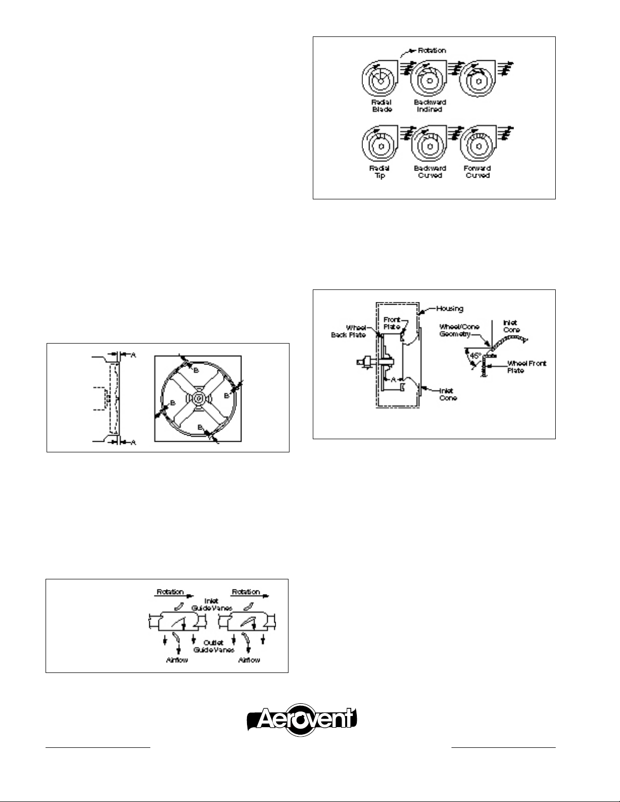
While checking the propeller alignment, it is good practice
to check its rotation. Normally the fan rotation is marked by
arrows on both the propeller and the fan casing. If omitted,
obliterated, or misapplied, check for proper rotation in Figure
4a.
Figure
3b
sides. Perpendicularity can be checked on BI and BIA fans by
measuring dimension “A” (Figure 5) at four points approximately 90° apart.
Radial blade impellers, material handling, pressure blowers,
and high pressure blowers are centered axially in the housing,
and can be checked by measuring the axial distance from one
blade or one point on the front plate to the side of the fan
Figure 5
NOTE: See IM-140 for dimensions.
housing at four points approximately 90° from each other.
While checking the impeller alignment, it is good practice
to check its rotation. Normally the fan rotation is marked by
arrows on the housing. If omitted, obliterated, or misapplied,
check for proper rotation in Figure 4b.
Centrifugal Fans
The fan shaft should be approximately centered in the clearance hole in the fan housing and perpendicular to the housing
Figure 4a
RH rotation.
Vaneaxial shown.
Standard propellers
similar, but less guide
vanes.
®
AEROVENT | WWW.AEROVENT.COM
6MWG09/10
5959 Trenton Lane N | Minneapolis, MN 55442 | Phone: 763-551-7500 | Fax: 763-551-7501
 Loading...