

Aerovent IM-100 User Manual

IM-100
August 2014
General Installation, Operation and Maintenance Instructions For Aerovent Products
Introduction
This manual has been prepared to guide the users of
Aerovent equipment in the proper installation, operation
and maintenance procedures to insure maximum equip
ment life and trouble-free operation.
-
Receiving
Products leaving the assembly plant have been
inspected and are in satisfactory operating condition.
The carrier assumes full responsibility for material from
the time it leaves the plant until it is delivered to the
user. Therefore, material should be inspected for dam
age immediately so that any damage claims against the
carrier can be made before acceptance of the shipment.
No equipment is to be returned without an authorized
returned goods tag.
-
Handling
All products must be handled with extreme care to
avoid misalignment of rotating components. Never lift a
unit assembly by using the shaft, drive sheaves, wheel
or motor as a point of attachment. If it is apparent
that slings will not clear a portion of the product being
hoisted, a spreader should be used to avoid damage.
Initial Operation
All Aerovent fans are lubricated at the factory and have
been given a run-in test before shipment. Read carefully
all installation and maintenance manuals before follow
ing the startup check list.
-
Safety Precautions
Any piece of machinery should be treated with respect
and not overconfidence. Overconfidence usually leads to
carelessness and carelessness leads to injury. Following
is a list of DOs and DO NOTs:
DO
1. Make sure the unit is stopped and electrical power
is locked out before putting hands into the inlet or
outlet openings or near the belt drive. A warning
sign on the START SWITCH cautioning not to start
is recommended when the unit is being serviced.
2. Follow maintenance instructions.
DO NOT
1. Put hands near or allow loose or hanging clothing to
be near belts or sheaves while the unit is running.
2. Put hands into inlet or outlet while the unit is run
ning. It is sometimes difficult to tell whether or not a
fan is running.... be sure it is not running and cannot
be operated before any inspection.
-
©2014 Aerovent
Startup Checklist
1. Inspect the equipment for any shipping damage.
Remove any foreign material such as tags or packing
from any moving parts or from within the fan housing.
2. Compare the voltage, hertz, and phase stamped on
the motor with the current characteristics of the line
to which the motor is to be connected.
3. Lock out the power source at the disconnect switch.
4. Turn motor, drive, and propeller by hand to see that
no misalignment has taken place in shipment. Check
V-belt drive for proper alignment and belt tension.
5. Check all bolts, screws and fasteners and tighten if
necessary. Make certain all set screws, locking col
lars and bearing mounting bolts are secure.
6. Secure and check clearance of access doors, belt
guards and inlet and outlet guards.
7. If equipped with dampers, check for correct linkage
operation. Make sure that the operator opens or
closes these control devices to the proper positions.
8. Jog the fan electrically and note the rotation. Reverse
two electrical leads, if necessary, to obtain proper
rotation as marked with rotation arrow on fan. Do
not allow the propeller to run backwards except
momentarily.
9. Centrifugal Fans: Close dampers as required for
adequate system resistance to prevent the motor
from overloading.
CAUTION: With fans that use the forward-curve or
radial type of wheel, it is possible to overload the motor
if the fan is operated at a lower static pressure than
that which the fan is rated. Check the catalog rating of
the fan for proper speed and resistance.
10. Start the fan and observe its operation.
11. Take a motor amp reading and compare with the
amp rating on the motor. (The actual running amps
should not exceed motor nameplate amps x service
factor, exceptions may be taken for air over motors.)
-
Fan Balance
Fan propellers are statically and dynamically balanced
within acceptable tolerances at the factory. Damage in
shipping and handling or poor installation of the unit
may upset the unit balance. A propeller that is not
properly balanced can lead to excessive vibration caus
ing undue wear on the entire unit. It is recommended
that after installation a vibration test be made on the
fan by an experienced technician.
CAUTION: For units furnished less final drive compo
nents at customer request, the addition of drive components in the field can create critical vibration modes.
Aerovent strongly recommends a final unit balance
procedure after all rotating components are installed.
Failure to do so voids Aerovent’s warranty.
-
-
All Aerovent fan assemblies are statically and dynamically balanced to Balance Quality Grade G6.3. Each
fan is factory run tested for vibration in accordance
with ANSI/AMCA 204-96 "Balance Quality and Vibration
Levels for Fans" to Fan Application Category BV-3, to
the following peak velocity values, filter-in, at the fan
test speed:
Fan Application Rigidly Mtd. Flexibly Mtd.
Category (in./sec.) (in./sec.)
BV-3 0.15 0.20
While fans are test run and carefully balanced in
the factory, vibration cannot be guaranteed under field
conditions due to mounting and installation variables.
Vibration measurements, when possible, should be
taken at each fan shaft bearing in two planes per
pendicular to the axis of rotation (planes to have 90
degree interval), and one measurement parallel to the
axis of rotation. On direct drive units, the perpendicular
measurements will be taken at each end of the motor
casing, taking care not to take measurements on the
fan shroud on TEFC motors. The axial measurement
can be taken on the motor foot or mounting base. In
some cases, primarily on axial flow units, it will not
be possible to take measurements at the bearings or
motor. On these units, the measurements should be
taken on the inner shell near the bearings. If this is not
possible, then take the readings on the outer shell near
the bearing locations.
If vibration is excessive, shut down the fan and
determine the cause.
Common Causes of Excessive Vibration
1. Support structure not sufficiently rigid or level.
Vibration amplified by resonance in ductwork or sup
-
port structure.
2. V-belt drive misalignment. Belt tension is too tight or
too loose.
3. Bearing locking collar or mounting bolts loose.
Propeller set screw loose.
4. Material accumulation on propeller.
5. Centrifugal Fans: Wheel rubbing on inlet cone.
Motors
Most integral horsepower totally-enclosed motors have
drain plugs in the end bells for drainage of condensa
tion. On all roof ventilators, the bottom or lower plug
has been removed for continuous drainage.
All other style fans are shipped with the drain plugs
installed. The user should remove the proper drain plug.
For horizontally mounted units with the motor in the
airstream, remove the downstream drain plug. For verti
cally mounted units, remove the bottom or lower drain
plug.
With motors supplied by the user, drain plugs may
not have been provided. Check with the motor manu
facturer regarding drainage and condensation.
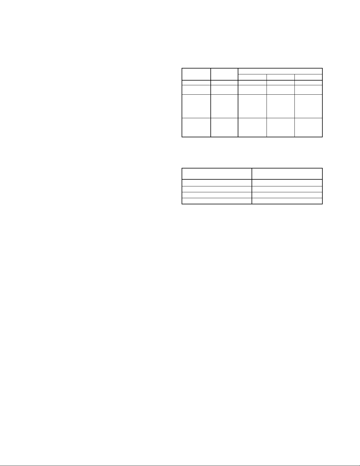
Lubrication Instructions for Ball
The table below suggests relubrication intervals for
motors on normal, steady running, light duty indoor
loads in relatively clean atmosphere at 40°C (105°F)
ambient temperature or less. Fractional horsepower
motors follow a schedule similar to that shown under
frames 143T to 215T.
Motor Lubrication Intervals
TYPE OF INSULA- FRAME SIZE
ENCLOSURE TION 143T–215T 254T–326T 364T–449T
Open-DP B 2 yrs. 18 mos. 1 yr.
Enclosed-FC B
Open-DP F
Enclosed-NV B
Enclosed-FC F
Open-DP H 1 yr. 9 mos. 6 mos.
Enclosed-Lint
Free-FC B
Enclosed-NV F
Enclosed-FC H
Enclosed-Lint
Free-FC F
NOTE: For motors over 1800 RPM, use
duty, dusty locations, use
tion/shock, use
SHAFT DIAMETER AMOUNT OF
(AT FACE OF BRACKET) GREASE TO ADD
1
1
2
1
⁄3 of tabled period.
VOLUME - REFERENCE TABLE
3
⁄4" to 11⁄4" 1/8 cu. in. or 0.1 oz.
1
⁄4" to 17⁄8" 1/4 cu. in. or 0.2 oz.
7
⁄8" to 23⁄8" 3/4 cu. in. or 0.6 oz.
3
⁄8" to 33⁄8" 2 cu. in. or 1.6 oz.
18 mos. 1 yr. 9 mos.
9 mos. 6 mos. 3 mos.
1
1
⁄2 of tabled period. For severe-duty high vibra-
⁄2 of tabled period. For heavy
Motors with no provision for lubrication are equipped
with sealed bearings and require no maintenance.
Motors mounted in inaccessible locations are provided
with extended grease lines to facilitate lubrication if
provisions for lubrication are provided. The bearings are
equipped with relief fittings to prevent over-lubrication.
The grease lines are filled with lubricant at the factory.
Procedure for Relubrication
1. Stop motor.
2. Remove grease relief plugs in bearing housings.
3. Grease with hand gun until new grease appears at
relief hole.
4. Run motor for ten (10) minutes before replacing relief
plugs.
CAUTION: Do not over-lubricate. This is a major cause
of bearing and motor failure. Make sure dirt and con
-
taminants are not introduced when adding grease.
Type of Grease
Lubricate with the following greases or their equivalent:
Amoco Rykon Premium #2
Chevron BRB-2 – Standard Oil or Calif.
SRI-2 – Standard Oil Company
Gadus S2 V100 2 - Shell Oil Company
Mobilith AW2
For motors lubricated with special greases, check lubri
cation tag on motor.
-
Bearing Motors
Grease-lubricated bearings, as furnished, are adequate
for a long period of operation without relubrication. A
good maintenance schedule for regreasing will vary
widely depending on motor size, speed and environment.
2 Aerovent IM-100
Lubrication Instructions for
Fan Ball Bearings
Bearings and grease lines on belt driven fans are lubricated in assembly. When lubrication is required, add
grease slowly while the shaft is rotating until grease
comes rapidly out of the seal.
For extreme conditions, lubricate according to experi
ence. For normal conditions, lubricate the bearings with
Mobilith AW2 or an equivalent.
Bearings and grease lines on axial fans that are
ordered for high moisture or above normal temperatures
have been lubricated with a special lubricant, Plastilube
#2. Lubricate at regular intervals with Plastilube #2 as
indicated in the special lubrication chart listed below.
Plastilube #2 is available from Sulflo, Inc. 1158 Erie
Avenue, North Tonowanda, New York 14120.
Special Lubrication Frequency For
High Temperature and High Moisture
AIRSTREAM
TEMPERATURE
TO 250°F 4500
TO 350°F 1500
TO 500°F 1000
WET ATMOSPHERE AT
ROOM TEMPERATURE
HOURS
1000 TO 1500
-
To rotate the fan, follow the procedure listed below:
The blade marked number 1 should be rotated to
top center. The blade number and date should be
recorded in a log book which is to be stored in a
protective pouch attached to the fan. During storage,
the fan propeller should be rotated by hand at least
ten (10) revolutions every thirty (30) days to circulate
the lubricant in the bearings in the motor or on the fan
shaft. After the tenth revolution, stop with a blade at
top center which is not the same one as is listed for
the previous date in the log book.
Fans which are V-belt driven should be prepared for
storage as follows:
Carefully remove the belts, coil them (without kinks)
in matched sets and place them in a heavy carton.
Mark the carton with fan identification and store the
carton in a dry, well-ventilated area. Belts must not be
left exposed to sunlight or subjected to storage ambient
conditions exceeding 85°F, 70% relative humidity. Belts
which show signs of deterioration should be replaced
prior to startup. Before reinstalling belts, review the sec
-
tion on “Belt Tension.”
NOTE: Procedures for storage of Aerovent equipment
as outlined above are intended as a general guide only.
Storage conditions will vary depending on the loca
tion. Common sense and practical experience should
determine to what extent the above procedures will be
followed.
Storage of Equipment
Fan Bearings
Since bearings tend to “breathe” on equipment stored
in areas with other than a constant temperature, mois
ture will condense internally. Therefore, it is necessary
to keep the bearings completely full of grease and
periodically rotated to make certain that all internal
parts are coated with grease. Even a full bearing will
eventually pick up moisture and, therefore, must be
periodically purged with new grease.
Grease should be purged from the bearings to
remove condensed moisture, and the fan wheel rotated
by hand every thirty (30) days. This practice should be
done more often if weather is severe or if there is a
wide variation in temperature.
CAUTION IN PURGING: The fan should be rotated
while greasing and high pressure pneumatic greasers
should be avoided. See “Lubrication Instructions for Fan
Motors
Motors must be stored under cover in a clean, dry,
vibration-free location. Remove sufficient packaging
material to allow circulation of air around the motor.
Maintain the temperature of the windings a few degrees
above that of the surrounding air to protect against
condensation. If the motor is equipped with internal
heaters, the heaters should be energized throughout
the storage period to prevent this condensation. If
the motor does not have internal heaters, this can be
accomplished using any other safe, reliable method of
heating. Measure and record the ambient air tempera
ture and winding temperature monthly.
In the event that the motor is not equipped with
internal heaters and space heating equipment is unavail
able, wrap the motor as tightly as possible with heavy
duty polyethylene. Enclose bags of desiccant (such as
silicagel) with the motor to minimize moisture problems.
Check the desiccant regularly and replace it periodically
as dictated by climate requirements.
Ball Bearings.”
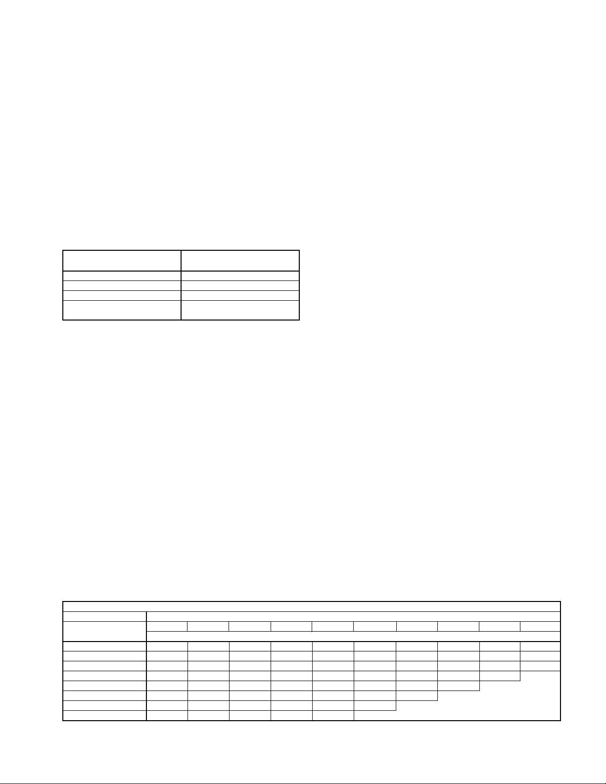
Lubrication Frequency for Horizontal Shaft Installations (see Note for vertical shaft installations)
LUBRICATION FREQUENCY
SHAFT SIZE
(INCHES)
1
1
1
2
2
3
3
NOTES: Reduce this lubrication frequency schedule by half for vertical shaft installations.
Consult manufacturer for specific recommendations.
1
1
⁄16 – 17⁄16 6 6 6 6 6 6 4 4 2 1
1
7
⁄8 – 23⁄16 6 6 4 4 2 2 1 1 1
1
7
⁄16 – 31⁄2 6 4 2 1 1 1
15
500 1000 1500 2000 2500 3000 3500 4000 4500 5000
RELUBRICATION CYCLE (MONTHS)
⁄2 – 1 6 6 6 6 6 6 4 4 2 2
⁄2 – 13⁄4 6 6 6 4 4 2 2 2 1 1
⁄4 –27⁄16 6 4 4 2 2 1 1 1
1
⁄2 – 3 6 4 4 2 1 1 1
⁄16 – 4 6 4 2 1 1
OPERATING SPEED (RPM)
-
-
Aerovent IM-100 3
 Loading...