

Aerovent ES-2-06 User Manual

ENGINEERING SUPPLEMENT
INSTALLATION, OPERATION & MAINTENANCE MANUAL
Fans with CE Mark
Contents
Introduction .........................................................................1
Personal Protection ............................................................
Hazardous Materials ..........................................................
Installation
Shipping and Receiving ................................................
Handling .........................................................................
Unit Storage ...................................................................
Foundations and Supporting Structures
- Industrial Fans .......................................................
Fan Installation - Factory Assembled Units ...............
Fan Installation - Disassembled Units ........................
Bearing Installation ........................................................
Grouting ..........................................................................
Drive Mounting ..............................................................
Flexible Couplings .........................................................
Duct Connections ..........................................................
Guards and Enclosures ................................................
Electrical Supply and Controls ....................................
Maintenance
Motor Maintenance .......................................................
Drive Maintenance .......................................................
Bearing Maintenance ................................................... 1 0
Wheel and Shaft Maintenance ...................................1 0
Structural Maintenance ............................................... 1 0
Fan Operation
Proper Use and Application ......................................
Sound ...........................................................................
Operation Checklist .....................................................
Optional Accessories ...................................................
Troubleshooting Guidelines .........................................
Disposal ........................................................................
Appendix A - Commercial Ventilator Installation
Instructions ...................................................................
Appendix B - Axial Fans ................................................
Introduction
This bulletin has been prepared to guide the users of
fans in the proper installation, operation and mainte
nance procedures to insure maximum equipment life
with trouble-free operation. Personnel operating or main
taining this equipment shall be trained in the proper
procedures for doing so.
Since many fans of this type have custom features or
components, please refer to the attached documentation
and appendices for additional information. When manu
facturers of components provide detailed installation and
operation manuals, they will be provided. Because of the
wide variety of equipment covered in this bulletin, the
instructions given here are general in nature.
For safe installation, startup and operational life of
this equipment, it is important that all involved with the
equipment be well versed in proper fan safety practices
and read this bulletin. Please review the safety section
before beginning any work. It is the user’s responsibil
ity to make sure that all requirements of good safety
practices and any applicable safety codes are strictly
adhered to. Only properly trained personnel should oper
ate and maintain this equipment.
©2006 Twin City Fan Companies, Ltd.
1
1
1
2
2
2
3
4
5
8
8
8
8
8
9
9
10
10
11
12
12
12
13
13
14
-
-
-
-
-
ES-2-06
Issue Date: 7-1-06
Rev. Date: NEW
Personal Protection
For safety reasons maintenance personnel should wear
personal protection equipment when attempting to main
tain fans. People with long hair are advised to tuck hair
back possibly into a cap.
Personal protection equipment should include the
following:
• Safety glasses or goggles approved by local safety
authority
• Protective shoes with steel toecaps and oil resistant soles
• Heavy gloves that can cope with sharp edges or
exposure to hazardous chemicals. This is especially
important when hazardous residues are present in
fans.
• Breathing apparatus if toxic gases or vapors are
expected to be present.
• Close fitting clothing
Do not wear:
• Rings
• Bracelets
• Necklaces
• Loose items of clothing
It is the responsibility of the maintenance personnel
to determine that the lighting is sufficient for the work
being performed. Additional portable lighting may be
required as there are no lighting fixtures supplied with
the fans.
Hazardous Materials
Twin City Fan Companies, Ltd. is not always made
aware of the materials that may be handled with a fan
and therefore can not warn the user of these hazards.
Because of this, the end user must identify the mate
rial hazards present and indicate this on the fan with
a warning label. If there is risk of residual hazardous
material being left in a fan if the gas or vapor being
handled can accumulate as a deposit, all maintenance
and operation personnel must be trained to handle such
hazards before having access to the fan.
Lubricants used on fan components could be hazard
ous if they contact someone’s eyes or are consumed.
For additional general safety practices for air moving
equipment, see AMCA Bulletin 410.
Installation
Shipping and Receiving
All Twin City Fan Companies, Ltd. products are carefully
constructed and inspected before shipment to insure the
highest standards of quality and performance. Compare
all components with the bill of lading or packing list to
verify that the proper unit was received. Check each unit
for any damage that may have occurred in transit. Any
damage should be reported immediately to the carrier and
the necessary damage report filed.
-
-
-
Handling
Handling of all air moving equipment should be conducted by trained personnel and be consistent with safe
handling practices. Verify the lift capacity and operat
ing condition of handling equipment. Maintain handling
equipment to avoid serious personal injury.
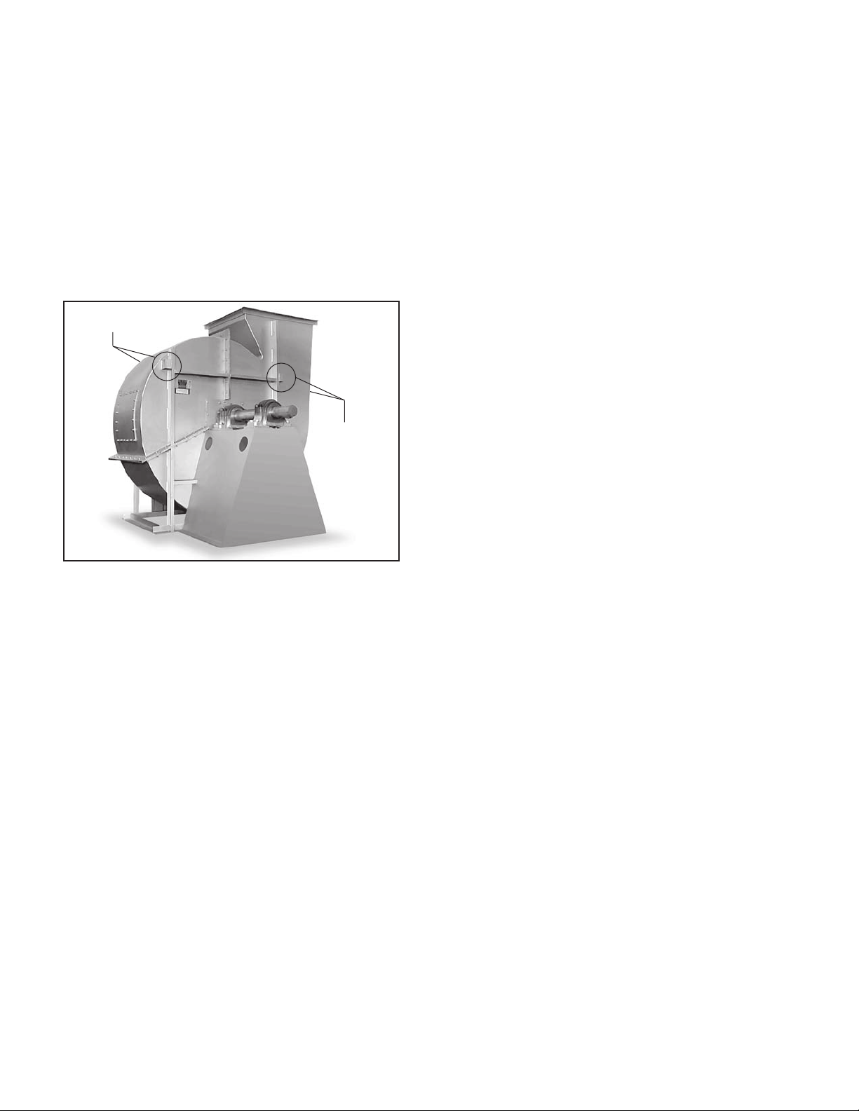
On most units, lifting lugs are fashioned to protect
the fan and fan housing from damage. Secure lifting
equipment to all provided lifting lugs to avoid instability
while moving the equipment. Units shipped completely
assembled may be lifted with slings and spreader bars.
(Use well-padded chains, cables or nylon straps.) Never
lift a fan by the inlet or discharge flange, shafting or
drives, wheel or impeller, motor or motor base, or in any
other manner that may bend or distort parts. Never lift
with slings or timbers passed through the fan inlets.
Figure 1. Lifting Lug Locations
Lifting Lugs
Lifting Lugs
Partial or disassembled units require special handling. All
parts should be handled in a fashion which protects the
coatings and parts from damage. Components should be
handled such that forces are not concentrated to avoid
bending or distortion.
The housing should be lifted using straps and spread
ers. Do not distort housing or side plates when lifting.
Bearing pedestals should be lifted using straps or
padded chains. Under no circumstance should an
attached or separated bearing pedestal be lifted by the
shaft, bearings, drives, motor or wheel.
The shaft and wheel assembly may be lifted using
a hoist and a spreader with a sling around the shaft
at points nearest the wheel. Use the spreader bar to
ensure that the slings do not push against the sides of
the wheel as this may distort the wheel. Take care not
to scratch the shaft where the wheel or bearings will
be mounted. Never lift or support the assembly by the
wheel. Always support the assembly by the shaft when
lifting or storing. Do not support the shaft or the wheel
on the housing sides.
Wheels shipped separately can be lifted by slings run
ning between the blades or around the hub. Never lift
the wheel by blades or flanges. Always transport wheels
by lifting. Do not roll the wheel as this can damage
coatings and change the balance of the wheel.
Bent shafting is a source of vibration and bearing
failure, so handle the shaft with care. Any scratches on
the shaft may be removed with fine emery cloth or a
stone.
For roof ventilators, also see instructions specific to
handling roof ventilators in Appendix A.
-
-
-
Pins to hold insulation to the housing are supplied
for some high temperature fan designs. Use caution
when handling and working around fans that have these
insulation pins as the points are sharp.
Unit Storage
If fan installation is to be delayed, store the unit in
an environmentally stable and protected area. Vibration
should not exceed 0.051 mm peak – peak displacement
at the storage site unless the fan is properly isolated
from the vibration. The unit should be reasonably pro
tected from any accidental impacts. Cover the fan to
protect coatings and to prevent any foreign material or
moisture from entering the inlet or discharge. Take care
to protect the motor, drives and bearings. The following
precautions should be taken during extended storage to
ensure the equipment is not damaged:
• Extended storage requires monthly inspections.
Check for corrosion or damage to the unit and for
debris within the fan.
• Bearings tend to take on moisture if the atmo
sphere they are stored in is not at a constant
temperature. To avoid corrosion, it is necessary to
keep the bearings full of grease and to rotate them
periodically. Even when full of grease, bearings will
take on moisture, so it is necessary to purge the
bearings with new grease to expel moisture every
thirty days. It is recommended that the bearings be
purged with grease while being rotated by hand.
Do not use high-pressure greasers as they may
ruin the bearing seals.
• The drives and belts should be removed if the fan
is to be stored for a prolonged period. The drives
should be labeled for service and stored in a dry
place. Belts should be removed, coiled without
kinks, placed in a heavy carton, and stored in a
dry, well-ventilated place. To prevent belt deterio
ration storage conditions should not exceed 85°F
and 70% humidity. If belts show signs of deteriora
tion, they should be replaced prior to startup.
• Motors should be stored in a clean, dry, vibrationfree location. The packaging should be opened up
enough to allow air circulation around the motor.
The winding temperature should be kept slightly
above that of the surroundings to prevent conden
sation. This can be accomplished by energizing
the internal heaters, if the motor is so equipped,
or by using space heaters. If it is impossible to
heat the windings, the motor should be wrapped
tightly with a waterproof material that also encloses
several bags of desiccant. Replace the desiccant
regularly to prevent moisture problems. The motor
rotor should also be rotated regularly (monthly) to
assure the bearing parts are well greased.
-
-
-
-
-
Foundations and Supporting Structures
— Industrial Fans
The best means of floor mounting a fan is on a welldesigned, flat, level concrete foundation. The foundation
should have a mass of at least three times that of
the supported assembly. The foundation should extend
150mm beyond the outer dimensions of the fan and
driver; however, it should be no more than twice the
area required for the equipment. If it is made larger, the
mass should be increased accordingly to resist rocking
modes of vibration. J or T type anchor bolts using one
size smaller than the nominal dimension of the base hole
shall be used. Anchor bolts should be tied into the rein
forcing bar of the foundation for the foundation. A pipe
-
2 Twin City Fan Companies Engineering Supplement 2-06
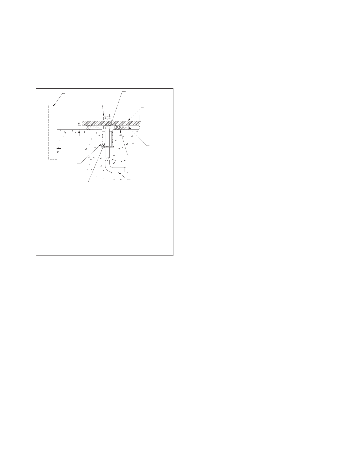
sleeve with a diameter of 2 to 21⁄2 times the anchor
bolt diameter should be provided around the anchor bolt
for final adjustment (see Figure 2). The mounting sur
face of the foundation should be smooth for good shim
contact. When deciding the thickness of the foundation,
approximately 25 to 40mm height should be allowed for
shimming, grouting, leveling, washers, nuts, etc.
The foundation plan on the customer submittal draw
ing indicates the mounting hole size and locations on
the fan.
Figure 2. Typical Foundation Section
Fan Installation - Factory Assembled Units
General instructions for industrial centrifugal fans – For Axial
-
fans and commercial ventilators, follow steps below noting
instructions specific to those fan types in Appendix A and B.
Follow proper handling instructions as given earlier.
1. Move the fan to the final mounting position.
2. Remove skid, crates and packing materials carefully.
-
3. If vibration isolation is to be used, place isolation
base on mounting bolts. Line up holes in fan base
with bolts as indicated on the foundation plan of
the customer submittal drawing.
4. Consult each specific fan’s submittal drawing for
proper installation arrangement and mounting dimen
sions. Place the fan on mounting structure. Carefully
level the unit (checking the level on the shaft) on
the foundation and shim as necessary using stain
less steel shims on both sides of each anchor bolt.
Anchor bolts are to be pre-tensioned per Table 1.
For metric grade bolts or materials not shown in
Table 1, check with bolt manufacturer for the proper
torque. (See details specific to commercial ventila
tors in appendix A for this step).
5. Check the alignment of the bearings. Shim or
reposition the bearings if necessary. In many split
housing roller bearings, the gap between the seal
carrier and housing can be measured with a feeler
NOTES:
¿ Temporary form for grout pouring.
¡ Hex nut, split ring lock washer and tapered or flat washer.
¬ 1" to 1.5" grout allowance to be filled with nonshrinking machinery
grout.
√ Pipe-bolt sleeve diameter 2 to 21/2 times bolt diameter for correc-
tion of alignment errors.
ƒ Care should be taken that anchor bolt sleeves are filled with
grout.
≈ J-Bolt leg should be fastened to foundation rebar.
≤ Shimming surface to be smooth, level, dressed if necessary.
« Full width stainless steel shims.
» Fan base angle or structural steel.
… Leveling nut, if used, should be backed off after shimming for final
tightening of hex nuts.
gage. The variation in this gap should be less than
half of the maximum gap measured. In roller bear
ings where this gap is not visible, alignment can
be verified by verifying the bearing is square with
the pedestal top. In ball bearings, the bearing outer
ring swivels in the housing to accommodate a small
amount of misalignment. Verify bearing set screws,
cap bolts, and collars are tightened per Tables 2a,
2b and 2c.
6. Check face alignment of sheaves on belt driven fans.
Parallel alignment should be within 5mm per meter of
center distance. Angular Misalignment should be less
than 1 degree. Check and record tension of belts
If a structural steel base or platform is to be used,
the structure must be designed for the weight of the fan,
live loads imposed by rotation of the rotor and driver,
and any external live loads. The structure should be
designed to ensure that no natural frequency will occur
within 30% of the fan speed. This is especially true if
the structure supports more than one fan.
Any ducting should have independent support. Do
not use the fan to support ducting. The fan frame
can be designed to carry some external loads. Consult
the factory if this is a concern. Isolating the fan from
ductwork with flex connections eliminates transmission
of vibration. Fans handling hot gases require expansion
joints at both the inlet and discharge to prevent exces
sive loads caused by thermal growth. Refer to AMCA
Publication 201 for good practices in ductwork geometry
and configuration. When possible, ductwork shall be
located where there is least risk of personnel tripping,
walking into or falling over the ductwork. If not possible,
warnings shall identify this hazard.
See Appendix A Commercial Ventilator Installation
Instructions for commercial ventilator foundation details.
Fans should not be located underneath other machin
ery where there might be a risk of harmful liquid falling
onto fans from above.
Fans should be installed where they are readily acces
sible to maintenance personnel, so that such personnel
are not required to stoop or crawl to access fans.
-
-
-
to see if it is sufficient. Proper belt tension is speci
fied on the included datasheet. If belt tension needs
adjustment, instructions on belt tensioning are given
in the Drive Mounting section of this manual. Sheaves
on belt driven fans are often provided with taperlock
bushings. When tightening bushing bolts, proceed in a
progressive manner to avoid cocking the tapered sur
faces between the bushing and the sheave. Bushing
bolt torque specifications are indicated in Table 3.
7. Check alignment of factory mounted couplings, as
they are subject to misalignment during shipment.
Realign if necessary in accordance with the instruc
tions which are included with the shipment. NOTE:
Most couplings need lubrication.
8. Make sure there is no rubbing or binding and that
the wheel-inlet cone or wheel to fan housing clear
ances and overlap are correct. Overlap values or
other dimensions to verify proper wheel location are
given in the included documentation specific to the
fan. Wheel clearance should be verified to match
the specified value and be uniform. The measured
values should be recorded.
9. Check the tightness of the wheel on the shaft per
Table 4. The measured torque should be recorded.
10. Check the tightness of foundation bolts, motor
mounting bolts, and bearing mounting bolts per
Table 1. For metric bolts or grades not specified in
Table 1, check proper torque values per the bolt
Twin City Fan Companies Engineering Supplement 2-06 3
manufacture.
-
-
-
-
-
-
-
-
11. Check that bearings are fully lubricated and check
Shaft
Centerline
Bearing
Pedestal
Sheave
Bearing
Inlet Funnel
Housing Side
Wheel
Assembled Bearing,
Shaft, Funnel, and
Housing. Frame
Angles Not Shown.
the oil level in the static oil lube systems (if
supplied).
12. Install any accessories shipped loose from the
factory.
Fan Installation - Disassembled Units
General instructions for industrial centrifugal fans – For Axial
fans (including mounting arrangements for inline centrifugal
fans), follow assembled fans instructions above and use
Appendix B for assembly details.
A unit is considered “disassembled” if any component
required for proper operation is shipped or supplied sepa
rately or in pieces. Reference earlier instructions concern
ing proper handling of fan components. Assembly shall
only be performed by trained personnel familiar with the
-
-
bore hubs), or for bushing bore hubs, progressively tighten the bushing bolts per Table 3.
Record the measured torque value.
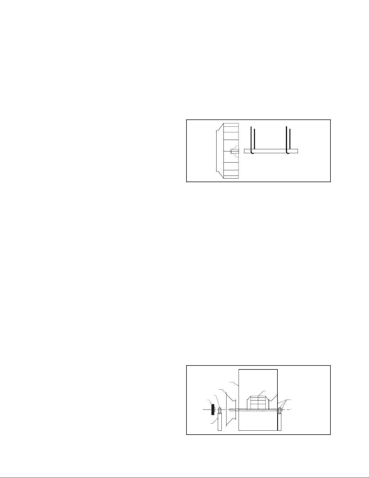
c. Insert shaft through opening in drive side. (If
splithoused unit, lower into position.)
d. Install bearings onto shaft. Do not tighten bear
ing setscrews at this time. The bearing housing
should be perpendicular and the bearing base
parallel to the axis of the shaft to prevent loads
caused by misalignment.
e. Mount assembly, bolt bearings to drive stand.
Shaft must be parallel with side of bearing
pedestal.
Figure 3. Drive Component Assembly
assembly of this type of equipment.
1. Move the lower half of the housing to its mounting
location (split housing).
2. Remove skids, crates, and packing materials carefully.
3. If vibration isolation is to be used, place the vibra
tion isolation base on mounting bolts. Line up holes
in fan base with bolts.
4. Place the lower housing on the mounting structure.
Carefully level the lower housing on the foundation
and shim as necessary using stainless steel shims
on both sides of each anchor bolt.
5. If the bearing pedestal(s) are separated they should
be installed next.
a. Move bearing pedestal(s) to mounting location.
b. Put vibration base, if any, in place. Set pedestal(s)
on bolt(s).
c. Do not distort bearing pedestal by forcing it to
align with a non-level foundation. Shim beneath
the pedestal as necessary.
d. Check the bearing centerline height. Adjust the
height to match centerline height of the hous
ing. High temperature units may require a lower
housing centerline when cold so that it will be
centered when hot.
e. Bring the bearing pedestal into square with the
housing using careful measurements or a large
square.
f. Bolt the pedestal into position.
6. If the wheel and shaft were shipped unassembled,
you must now install the shaft in the wheel.
a. First use solvent to clean the protective coating
off the shaft. Check all surfaces for corrosion or
nicks and clean if necessary with fine emery cloth
or a stone. After thoroughly cleaning the shaft
8. Arrangement 3 (Split-housed) units (See Figure 4):
a. Parts on DWDI units are assembled in the fol
lowing order as viewed from opposite drive side:
Bearing bar assembly and opposite bearing, fun
nel, (housing side), wheel, (housing side), funnel,
drive side bearing bar assembly, drive bearing
and sheaves. Mount bearing bar assembly to
housing. Center wheel in funnels.
b. Parts on SWSI units are assembled in the
following order as viewed from opposite drive
side: Bearing bar assembly and opposite bearing,
-
funnel, (housing side), wheel, (housing side),
drive side bearing bar assembly, drive bearing
and sheaves. Mount bearing bar assembly to
housing.
c. Assemble parts in above order on shaft.
d. Move assembly into position. Lightly bolt bearings
into place.
e. Shaft should be parallel with discharge of hous
ing. Move bearings to accommodate. Follow
bearing alignment instructions per step 5 in fac
tory assembled units section above.
f. Level shaft; shim bearings if required. Tighten
bearing setscrews.
Figure 4. Split-housed Drive Component Assembly
with solvent, do not touch it with bare hands as
perspiration can cause rust or pitting over time.
b. Remove keys from the shaft.
c. Clean the inside of the wheel bore with solvent.
Make sure the setscrews will not interfere when
inserting the shaft into the wheel bore.
7. Arrangement 1, 9 or 10: Drive Component
Assembly:
a. Insert shaft into wheel from back side of wheel
b. When shaft is flush with wheel hub, put key into
4 Twin City Fan Companies Engineering Supplement 2-06
(Fig 3).
keyway and tighten wheel setscrews (for straight
9. Install motor on base. Carefully align shafts for drive
installation.
-
-
-
-
-
10. Mount drives as follows:
a. Slip (do not pound) proper sheave onto cor-
responding shaft. CAUTION: PLACING FAN
SHEAVE ON MOTOR CAN OVERSPEED WHEEL
AND CAUSE STRUCTURAL FAILURE.
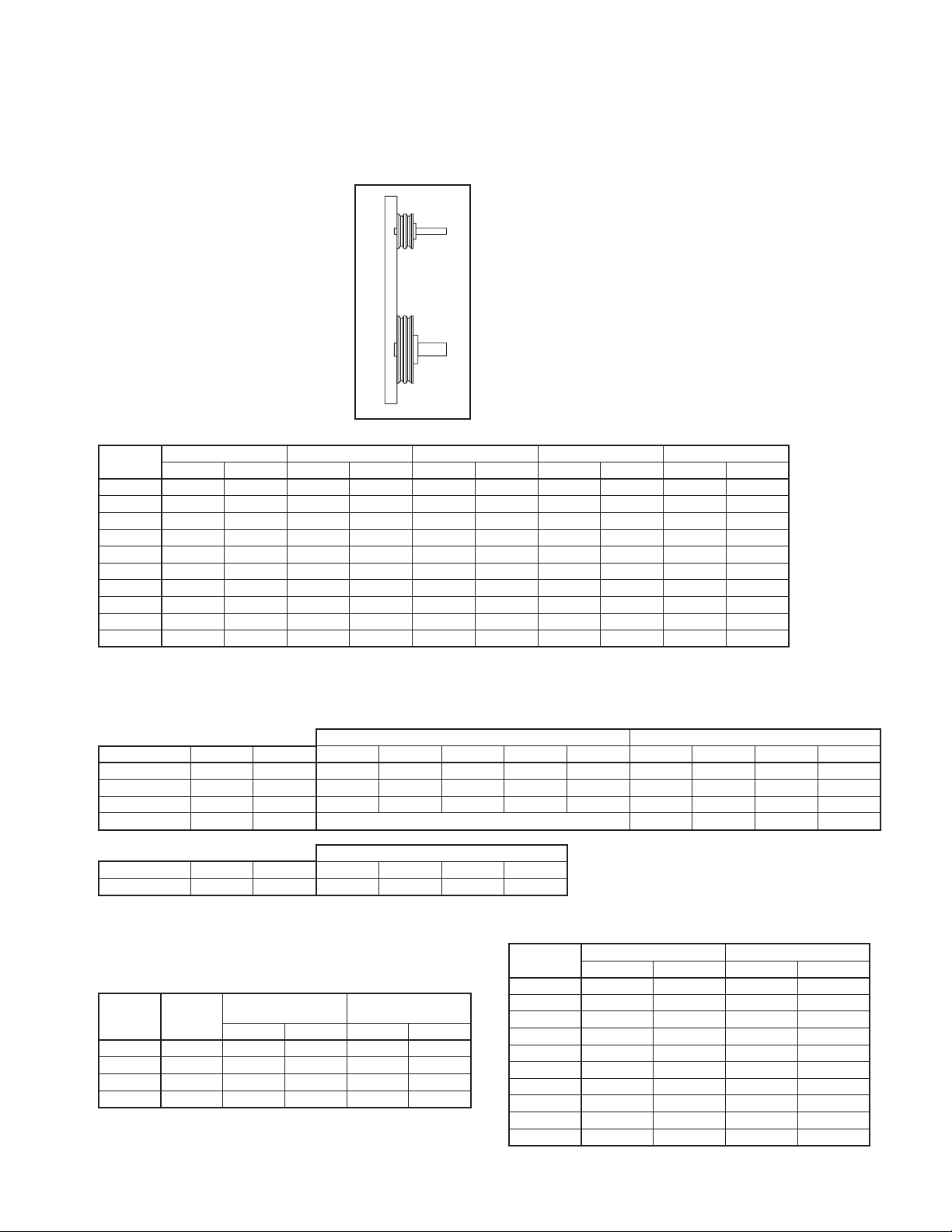
Figure 5.
b. Align sheaves with a straight
edge extended along the
-
Sheave Alignment
perimeters of both sheaves,
just making contact in two
places on outside perimeters
of both sheaves (see Figure
5). Parallel alignment should
be within 5mm per meter
of center distance. Angular
Misalignment should be less
than 1 degree.
c. Tighten down sheave bolts.
d. Install a matched set of
belts. Adjust belt tension as
indicated in “Drive Mounting”
step #3.
Table 1. Bolt Tightening Torque
Size
1/4 - 20
5/16 - 18
3/8 - 16
7/16 - 14
1/2 - 13
5/8 - 11
3/4 - 10
7/8 - 9
1 - 8
1 1/4 - 7
Grade 2 Grade 5 Grade 8 Aluminum Stainless
(Ft - lbs) (N - m) (Ft - lbs) (N - m) (Ft - lbs) (N - m) (Ft - lbs) (N - m) (Ft - lbs) (N - m)
5.5 7.5 8 10.8 12 16.3 3.8 5.2 6.3 8.5
11 15 17 23 25 34 6.7 9.1 11 15
22 30 30 41 45 61 11.9 16 19 26
30 41 50 68 70 95 19 26 31 42
55 75 75 102 110 149 26 35 43 58
100 136 150 203 220 298 59 80 92 125
170 230 270 366 380 515 81 110 128 174
165 224 430 583 600 813 125 169 194 263
250 339 645 874 900 1220 184 249 287 389
500 678 1120 1518 1500 2034 336 456 523 709
e. Tighten belts to proper belt tension. Record the
belt tension used. See drive mounting section for
tensioning instructions. Proper tension is specified
in the datasheet included with the fan.
11. Fans that have motors and drives mounted at the
factory are trim balanced prior to shipment. This
is not possible on units that are shipped without
motors and drives. The addition of drive compo
nents in the field can create unbalance forces. Twin
City Companies, Ltd. recommends final balancing
of the unit after the drive components are installed.
Failure to do so voids the Twin City Fan Companies,
Ltd. warranty.
12. Repeat the installation checks indicated for factory
assembled units to assure proper tightness and
alignment of all components.
Bearing Installation
Bearings are only to be field installed when accompanied by installation instructions from the bearing manu
facturer. When field installation is required, follow the
manufactures instructions carefully to install bearings.
-
Table 2a. Bearing Cap Bolt Torque Specifications (see page 6)
Table 2b. Metric Set Screw Torque Specifications
METRIC SHAFTS SET SCREW SIZE LOCKING COLAR SCREW SIZE
Manufacturer BRG ID Units M5 M6 M8 M10 M12 M4 M5 M6 M8
Dodge
Dodge
Dodge
SKF
Manufacturer BRG ID Units 12-35mm 40-45mm 50-65mm
SKF
Table 2c. IP Set Screw Torque Specifications (see page 7)
Table 3. Browning Split Taper Bushing Tightening Torque
Bolt
Size
1/4 - 20
5/16 - 18
3/8 - 16
1/2 - 13
S2000 N-m - - 17.8 35 57 - - - SCAH N-m 3.4 6.9 16 28 51 5.85 10.75 20.5 45
SCMAH N-m 3.4 6.9 16 28 51 5.85 10.75 20.5 45
SY N-m See Below 4.2 7.4
BEARING DIAMETER
70-100mm
SY N-m 4 6.5 16.5 28.5
Table 4. Set Screw Tightening Torque (other than bearing set screws)
Steel Set Screws Stainless Set Screws
Ft - lbs N - m Ft - lbs N - m
5.5 7.5 5.8 7.9
11 15 11 15
22 30 19 26
30 41 28 38
55 75 42 57
100 136 82 111
170 230 115 156
165 224 - 250 339 - 500 678 - -
Bushing
Type
H 8 11 8 11
P, B 17 23 13 18
Q, R 30 41 24 33
S 70 95 - -
Iron/Steel Hub,
Sheave
Ft - lbs N - m Ft - lbs N - m
Aluminum
Hub
Set Screw
Size
1/4 - 20
5/16 - 18
3/8 - 16
7/16 - 14
1/2 - 13
5/8 - 11
3/4 - 10
7/8 - 9
1 - 8
1 1/4 - 7
Twin City Fan Companies Engineering Supplement 2-06 5
 Loading...