

Aerohive HIVEAP20AG User Manual
Aerohive Deployment Guide

Aerohive Deployment Guide
For HiveAP and HiveManager Devices
Aerohive Technical Publications
Copyright Notice
Copyright © 2008 Aerohive Networks, Inc. All rights reserved.
Aerohive Networks, the Aerohive Networks logo, HiveOS, HiveAP, and HiveManager are trademarks of Aerohive
Networks, Inc. All other trademarks and registered trademarks are the property of their respective companies.
Information in this document is subject to change without notice. No part of this document may be reproduced or
transmitted in any form or by any means, electronic or mechanical, for any purpose, without receiving written
permission from:
Aerohive Networks, Inc.
3150-C Coronado Drive
Santa Clara, CA 95054
P/N 330002-06, Rev. A
1

HiveAP Compliance Information
HiveAP Compliance Information
Federal Communication Commission Interference
Statement
This equipment has been tested and found to comply with the limits for
a Class B digital device, pursuant to Part 15 of the FCC Rules. These
limits are designed to provide reasonable protection against harmful
interference in a residential installation. This equipment generates,
uses and can radiate radio frequency energy and, if not installed and
used in accordance with the instructions, may cause harmful
interference to radio communications. However, there is no guarantee
that interference will not occur in a particular installation. If this
equipment does cause harmful interference to radio or television
reception, which can be determined by turning the equipment off and
on, the user is encouraged to try to correct the interference by one of
the following measures:
• Reorient or relocate the receiving antenna
• Increase the separation between the equipment and receiver
• Connect the equipment into an outlet on a circuit different from
that to which the receiver is connected
• Consult the dealer or an experienced radio/TV technician for help
FCC Caution: Any changes or modifications not expressly approved by
the party responsible for compliance could void the user's authority to
operate this equipment. This device complies with Part 15 of the FCC
Rules. Operation is subject to the following two conditions: (1) This
device may not cause harmful interference, and (2) this device must
accept any interference received, including interference that may
cause undesired operation.
Important: FCC Radiation Exposure Statement
This equipment complies with FCC radiation exposure limits set forth
for an uncontrolled environment. This equipment should be installed
and operated with a minimum distance of 20 centimeters (8 inches)
between the radiator and your body. This transmitter must not be colocated or operating in conjunction with any other antenna or
transmitter.
Wireless 5 GHz Band Statements
To comply with FCC regulations, do not use channels 36, 40, 44, and 48
in the 5.15–5.25 GHz band when HiveAPs are deployed outdoors. In
addition, the transmission power is limited to a maximum of 15 dBm.
Because radar systems use some bands in the 5 GHz spectrum, WLAN
devices operating in these bands must use DFS (Dynamic Frequency
Selection) to detect radar activity and switch channels automatically to
avoid interfering with radar operations. DFS is required for WLAN
devices operating within the 5.25–5.35 GHz UNII-2 and the 5.47–5.725
UNII Mid-Band spectrums in the FCC regions of North America and the
ETSI regions in the European Community. DFS is not required for WLAN
devices operating in the 5.725-5.850 GHz spectrum in FCC regions. (The
5.725-5.850 GHz spectrum is not available for wireless use in ETSI
regions.) HiveAP 300 series models support DFS-FCC and DFS-ETSI and
are permitted to operate in the 5.25–5.35 GHz and 5.47–5.725 GHz
bands in outdoor deployments in the FCC and ETSI regions.
Note: The term "IC" before the radio certification number signifies that
Industry Canada technical specifications were met.
Industry Canada - Class B
This digital apparatus does not exceed the Class B limits for radio noise
emissions from digital apparatus as set out in the interference-causing
equipment standard entitled "Digital Apparatus," ICES-003 of Industry
Canada.
Cet appareil numérique respecte les limites de bruits radioélectriques
applicables aux appareils numériques de Classe B prescrites dans la
norme sur le matériel brouilleur: "Appareils Numériques," NMB-003
édictée par l'Industrie.
Wi-Fi Certification
The Wi-Fi CERTIFIED™ Logo is a certification mark of the Wi-Fi
Alliance®. The Aerohive HiveAP 20 ag has been certified for WPA™,
WPA2™, WMM® (Wi-Fi Multimedia™), WMM Power Save, and the
following types of EAP (Extensible Authentication Protocol):
• EAP-TLS
• EAP-TTLS/MSCHAPv2
• PEAPv0/EAP-MSCHAPv2
• PEAPv1/EAP-GTC
• EAP-SIM
EC Conformance Declaration
Marking by the above symbol indicates compliance with the Essential
Requirements of the R&TTE Directive of the European Union (1999/5/
EC). This equipment meets the following conformance standards:
• EN 60950-1 (IEC 60950-1) - Product Safety
• EN 301 893 - Technical requirements for 5 GHz radio equipment
• EN 300 328 - Technical requirements for 2.4 GHz radio equipment
• EN 301 489-1 / EN 301 489-17 - EMC requirements for radio
equipment
Countries of Operation and Conditions
of Use in the European Community
HiveAPs are intended to be operated in all countries of the European
Community. Requirements for indoor vs. outdoor operation, license
requirements and allowed channels of operation apply in some
countries as described below.
• Before operating a HiveAP, the admin or installer must properly
enter the current country of operation in the command line
interface as described in "Appendix A Country Codes" on page177.
Note to U.S. model owners: To comply with U.S. FCC regulations,
the country selection function has been completely removed from
all U.S. models. The above function is for non-U.S. models only.
• HiveAPs automatically limit the allowable channels determined by
the current country of operation. Incorrectly entering the country
of operation might result in illegal operation and cause harmful
interference to other systems. The admin is obligated to ensure
HiveAPs are operating according to the channel limitations,
indoor/outdoor restrictions and license requirements for each
European Community country as described in this section.
• HiveAPs can be operated indoors or outdoors in all countries of the
European Community using the 2.4 GHz band: Channels 1 - 13,
except where noted below.
– In Italy, you must apply for a license from the national
spectrum authority to operate a HiveAP outdoors.
– In Belgium outdoor operation is only permitted using the 2.46 -
2.4835 GHz band: Channel 13.
– In France outdoor operation is only permitted using the 2.4 -
2.454 GHz band: Channels 1 - 7.
• HiveAPs using the 5.15–5.25 GHz band (Channels 36, 40, 44, 48)
are restricted to indoor use when operated in the European
Community. Because the frequency ranges 5.25–5.35 and 5.47–
5.725 are affected by DFS (Dynamic Frequency Selection), HiveAP
20 and 28 models block channels 52, 56, 60, 64, and 100, 104, 108,
112, 116, 120, 124, 128, 132, 136, 140.
2 Aerohive
HIVEAP COMPLIANCE INFORMATION
The availability of some specific channels and/or operational
frequency bands are country dependent and are firmware
programmed at the factory to match the intended destination.
The firmware setting is not accessible by the end user.
• The 5 GHz Turbo Mode feature is not allowed for operation in any
European Community country. You can find the current setting for
this feature in two places. In the HiveManager GUI, click
Configuration > Network Objects> Radio Profiles > profile >
Advanced. In the HiveAP CLI, enter this command: show radio
profile profile. By default, Turbo Mode is disabled.
Declaration of Conformity in Languages
of the European Community
EnglishHereby, Edgecore, declares that this Radio LAN
FinnishValmistaja Edgecore vakuuttaa täten että Radio LAN
Dutch Hierbij verklaart Edgecore dat het toestel Radio
FrenchPar la présente Edgecore déclare que cet appareil
SwedishHärmed intygar Edgecore att denna Radio LAN
Danish Undertegnede Edgecore erklærer herved, at
GermanHiermit erklärt Edgecore, dass sich dieser/diese/
Greek
Italian Con la presente Edgecore dichiara che questo Radio
SpanishPor medio de la presente Manufacturer declara que
PortugueseManufacturer declara que este Radio LAN device
device is in compliance with the essential
requirements and other relevant provisions of
Directive 1999/5/EC.
device tyyppinen laite on direktiivin 1999/5/EY
oleellisten vaatimusten ja sitä koskevien direktiivin
muiden ehtojen mukainen.
LAN device in overeenstemming is met de
essentiële eisen en de andere relevante bepalingen
van richtlijn 1999/5/EG.
Bij deze Edgecore dat deze Radio LAN device
voldoet aan de essentiële eisen en aan de overige
relevante bepalingen van Richtlijn 1999/5/EC.
Radio LAN est conforme aux exigences essentielles
et aux autres dispositions relatives à la directive
1999/5/CE.
device står I överensstämmelse med de väsentliga
egenskapskrav och övriga relevanta bestämmelser
som framgår av direktiv 1999/5/EG.
følgende udstyr Radio LAN device overholder de
væsentlige krav og øvrige relevante krav i direktiv
1999/5/EF.
dieses Radio LAN device in Übereinstimmung mit
den grundlegenden Anforderungen und den anderen
relevanten Vorschriften der Richtlinie 1999/5/EG
befindet". (BMWi)
Hiermit erklärt Edgecore die Übereinstimmung des
Gerätes Radio LAN device mit den grundlegenden
Anforderungen und den anderen relevanten
Festlegungen der Richtlinie 1999/5/EG. (Wien)
LAN device è conforme ai requisiti essenziali ed alle
altre disposizioni pertinenti stabilite dalla direttiva
1999/5/CE.
el Radio LAN device cumple con los requisitos
esenciales y cualesquiera otras disposiciones
aplicables o exigibles de la Directiva 1999/5/CE.
está conforme com os requisitos essenciais e outras
disposições da Directiva 1999/5/CE.
HiveAP 20 ag Safety Compliance
Power Cord Safety
Please read the following safety information carefully before installing
a HiveAP.
Warning: Installation and removal of HiveAPs must be carried out by
qualified personnel only.
• HiveAPs must be connected to an earthed (grounded) outlet to
comply with international safety standards.
• Do not connect HiveAPs to an A.C. outlet (power supply) without
an earth (ground) connection.
• The appliance coupler (the connector to the unit and not the wall
plug) must have a configuration for mating with an EN 60320/IEC
320 appliance inlet.
• The socket outlet must be near the HiveAP and easily accessible.
You can only remove power from a HiveAP by disconnecting the
power cord from the outlet.
• HiveAPs operate under SELV (Safety Extra Low Voltage) conditions
according to IEC 60950. The conditions are only maintained if the
equipment to which they are connected also operates under SELV
conditions.
• A HiveAP receiving power through its PoE (Power over Ethernet)
interface must be in the same building as the equipment from
which it receives power.
France and Peru only:
HiveAPs cannot be powered from IT* supplies. If your supplies are of IT
type, then a HiveAP must be powered by 230 V (2P+T) via an isolation
transformer ratio 1:1, with the secondary connection point labelled
Neutral, connected directly to earth (ground).
* Impédance à la terre
Important! Before making connections, make sure you have the correct
cord set. Check it (read the label on the cable) against the description
on the following page.
Power Cord Set
U.S.A.
and Canada
DenmarkThe supply plug must comply with Section 107-2-D1,
SwitzerlandThe supply plug must comply with SEV/ASE 1011.
U.K. The supply plug must comply with BS1363 (3-pin 13 A)
EuropeThe supply plug must comply with CEE7/7
Veuillez lire attentivement les informations de sécurité relatives à
l'installation d'un point d'accès HiveAP.
The cord set must be UL-approved and CSA certified.
Minimum specifications for the flexible cord:
- No. 18 AWG not longer than 2 meters, or 16 AWG
- Type SV or SJ
- 3-conductor
The cord set must have a rated current capacity of at
least 10 A.
The attachment plug must be an earth-grounding
type with NEMA 5-15P (15 A, 125 V) or NEMA 6-15 (15
A, 250 V) configuration.
Standard DK2-1a or DK2-5a.
and be fitted with a 5 A fuse that complies with
BS1362.
The mains cord must be <HAR> or <BASEC> marked and
be of type HO3VVF3GO.75 (minimum).
("SCHUKO").
The mains cord must be <HAR> or <BASEC> marked and
be of type HO3VVF3GO.75 (minimum).
IEC-320 receptacle.
Deployment Guide 3

HiveAP Compliance Information
Avertissement: L'installation et la dépose de points d'accès HiveAP
doivent être effectuées uniquement par un personnel qualifié.
• Les points d'accès HiveAP doivent être connectés sur le secteur
par une prise électrique munie de terre (masse) afin de respecter
les standards internationaux de sécurité.
• Ne jamais connecter des points d'acc ès HiveAP à une alimentation
électrique non-pourvue de terre (masse).
• Le boitier d'alimentation (connecté directement au point d'accès)
doit être compatible avec une entrée électrique de type EN
60320/IEC 320.
• La prise secteur doit se trouver à proximité du point d'accès
HiveAP et facilement accessible. Vous ne pouvez mettre hors
tension un point d'accès HiveAP qu'en débranchant son
alimentation électrique au niveau de cette prise.
• Pour des raisons de sécurité, le point d'accès HiveAP fonctionne à
une tension extrêmement basse, conformément à la norme IEC
60950. Les conditions de sécurité sont valables uniquement si
l'équipement auquel le point d'accès HiveAP est raccordé
fonctionne également selon cette norme.
• Un point d'accès HiveAP alimenté par son interface réseau
Ethernet en mode POE (Power over Ethernet) doit être
physiquement dans le même bâtiment que l'équipement réseau
qui lui fournit l'électricité.
France et Pérou uniquement:
Un point d'accès HiveAP ne peut pas être alimenté par un dispositif à
impédance à la terre. Si vos alimentations sont du type impédance à la
terre, alors le point d'accès HiveAP doit être alimenté par une tension
de 230 V (2P+T) via un transformateur d'isolement à rapport 1:1, avec
le neutre connecté directement à la terre (masse).
Cordon électrique - Il doit être agréé dans le pays d'utilisation
Etats-Unis
et Canada
DanemarkLa prise mâle d'alimentation doit respecter la section
SuisseLa prise mâle d'alimentation doit respecter la norme
EuropeLa prise secteur doit être conforme aux normes CEE
Le cordon doit avoir reçu l'homologation des UL et un
certificat de la CSA.
Les spécifications minimales pour un cable flexible
- AWG No. 18, ou AWG No. 16 pour un cable de
longueur inférieure à 2 mètres.
- Type SV ou SJ
- 3 conducteurs
Le cordon doit être en mesure d'acheminer un
courant nominal d'au moins 10 A.
La prise femelle de branchement doit être du type à
mise à la terre (mise à la masse) et respecter la
configuration NEMA 5-15P (15 A, 125 V) ou NEMA 615P (15 A, 250 V).
107-2 D1 de la norme DK2 1a ou DK2 5a.
SEV/ASE 1011.
7/7 ("SCHUKO").
LE cordon secteur doit porter la mention <HAR> ou
<BASEC> et doit être de type HO3VVF3GO.75
(minimum).
Warnung: Die Installation und der Ausbau des Geräts darf nur durch
Fachpersonal erfolgen.
• Das Gerät sollte nicht an eine ungeerdete Wechselstromsteckdose
angeschlossen werden.
• Das Gerät muß an eine geerdete Steckdose angeschlossen werden,
welche die internationalen Sicherheitsnormen erfüllt.
• Der Gerätestecker (der Anschluß an das Gerät, nicht der
Wandsteckdosenstecker) muß einen gemäß EN 60320/IEC 320
konfigurierten Geräteeingang haben.
• Die Netzsteckdose muß in der Nähe des Geräts und leicht
zugänglich sein. Die Stromversorgung des Geräts kann nur durch
Herausziehen des Gerätenetzkabels aus der Netzsteckdose
unterbrochen werden.
• Der Betrieb dieses Geräts erfolgt unter den SELV-Bedingungen
(Sicherheitskleinstspannung) gemäß IEC 60950. Diese Bedingungen
sind nur gegeben, wenn auch die an das Gerät angeschlossenen
Geräte unter SELV-Bedingungen betrieben werden.
Stromkabel. Dies muss von dem Land, in dem es benutzt wird
geprüft werden:
U.S.A.
und
Kanada
DanemarkDieser Stromstecker muß die ebene 107-2-D1, der
SchweizDieser Stromstecker muß die SEV/ASE
EuropeEurope Das Netzkabel muß vom Typ HO3VVF3GO.75
Der Cord muß das UL gepruft und war das CSA
beglaubigt.
Das Minimum spezifikation fur der Cord sind:
- Nu. 18 AWG - nicht mehr als 2 meter, oder 16 AWG.
- Der typ SV oder SJ
- 3-Leiter
Der Cord muß haben eine strombelastbarkeit aus
wenigstens 10 A.
Dieser Stromstecker muß hat einer erdschluss mit der
typ NEMA 5-15P (15A, 125V) oder NEMA 6-15P (15A,
250V) konfiguration.
standard DK2-1a oder DK2-5a Bestimmungen
einhalten.
1011Bestimmungen einhalten.
(Mindestanforderung) sein und die Aufschrift <HAR>
oder <BASEC> tragen.
Der Netzstecker muß die Norm CEE 7/7 erfüllen
("SCHUKO").
Bitte unbedingt vor dem Einbauen des HiveAP die folgenden
Sicherheitsanweisungen durchlesen.
Liability Disclaimer
Installation of Aerohive equipment must comply with local and national electrical codes and with other regulations governing this type of installation.
Aerohive Networks, its channel partners, resellers, and distributors assume no liability for personal injury, property damage, or violation of
government regulations that may arise from failing to comply with the instructions in this guide and appropriate electrical codes.
4 Aerohive

Contents
Chapter 1 Preparing for a WLAN Deployment...............................................9
Assessing Your Requirements.............................................................................10
Planning......................................................................................................10
Upgrading from Existing Wi-Fi...................................................................................10
New WLAN Deployment...........................................................................................11
Site Surveys.........................................................................................................12
Budgeting Wi-Fi: The Chicken and Egg Problem..............................................................13
Planning Tools.................................................................................................13
Associated Access Point Costs...............................................................................14
Bandwidth Assumptions for Wi-Fi...............................................................................14
Overcoming Physical Impediments..............................................................................15
Preparing the Wired Network for Wireless....................................................................17
Operational Considerations................................................................................18
Tuning...............................................................................................................18
Troubleshooting....................................................................................................18
Management........................................................................................................18
Deploying with Confidence.......................................................................................18
Basic Wi-Fi Concepts.......................................................................................19
Chapter 2 The HiveAP 20 ag Platform.......................................................23
HiveAP 20 Product Overview..............................................................................24
Ethernet and Console Ports......................................................................................26
Status LEDs.........................................................................................................27
Antennas............................................................................................................28
Mounting the HiveAP 20....................................................................................29
Ceiling Mount.......................................................................................................29
Surface Mount......................................................................................................30
Device, Power, and Environmental Specifications.....................................................31
Chapter 3 The HiveAP 28 Outdoor Platform...............................................33
HiveAP 28 Product Overview..............................................................................34
Ethernet Port.......................................................................................................35
Power Connector..................................................................................................36
Antennas............................................................................................................37
Deployment Guide 5

Contents
Mounting the HiveAP 28 and Attaching Antennas......................................................38
Pole Mount..........................................................................................................39
Strand Mount.......................................................................................................40
Surface Mount......................................................................................................41
Attaching Antennas................................................................................................42
Connecting Antennas Directly to the HiveAP 28..........................................................42
Mounting Antennas Separately..............................................................................42
Device, Power, and Environmental Specifications.....................................................44
Chapter 4 The HiveAP 340 Platform.........................................................45
HiveAP 340 Product Overview.............................................................................46
Ethernet and Console Ports......................................................................................48
Smart PoE......................................................................................................49
Aggregate and Redundant Interfaces......................................................................49
Console Port...................................................................................................51
Status LEDs.........................................................................................................52
Antennas............................................................................................................52
MIMO............................................................................................................53
Using MIMO with Legacy Clients.............................................................................55
Mounting the HiveAP 340..................................................................................56
Ceiling Mount.......................................................................................................56
Locking the HiveAP 340......................................................................................57
Surface Mount......................................................................................................58
Device, Power, and Environmental Specifications.....................................................59
Chapter 5 The HiveManager Platform.......................................................61
Product Overview...........................................................................................62
Ethernet and Console Ports......................................................................................63
Status LEDs.........................................................................................................64
Rack Mounting the HiveManager..........................................................................65
Device, Power, and Environmental Specifications.....................................................66
Chapter 6 The High Capacity HiveManager Platform.....................................67
Product Overview...........................................................................................68
Rack Mounting the High Capacity HiveManager........................................................70
Replacing Power Supplies..................................................................................73
Replacing Hard Disk Drives................................................................................74
Device, Power, and Environmental Specifications.....................................................75
6 Aerohive

Chapter 7 Using HiveManager.................................................................77
Installing and Connecting to the HiveManager GUI....................................................79
Introduction to the HiveManager GUI....................................................................82
Cloning Configurations............................................................................................83
Multiselecting......................................................................................................83
Sorting Displayed Data............................................................................................84
HiveManager Configuration Workflow...................................................................85
Updating Software on HiveManager......................................................................86
Updating HiveOS Firmware................................................................................87
Updating HiveAPs in a Mesh Environment......................................................................88
Chapter 8 HiveManager Configuration Examples..........................................89
Example 1: Mapping Locations and Installing HiveAPs................................................91
Setting Up Topology Maps........................................................................................91
Preparing the HiveAPs............................................................................................94
Using SNMP.....................................................................................................94
Using MAC Addresses..........................................................................................95
Example 2: Defining Network Objects and MAC Filters...............................................97
Defining a MAC OUI................................................................................................97
Mapping the MAC OUI and Services to Aerohive Classes................................................98
Defining VLANs...................................................................................................100
Creating IP Addresses...........................................................................................101
Creating a MAC Filter...........................................................................................103
Example 3: Providing Guest Access....................................................................104
Guest Access with Preshared Keys............................................................................104
Guest Access with Captive Web Portal.......................................................................105
Captive Web Portal with External DHCP and DNS Servers............................................105
Captive Web Portal with Internal DHCP and DNS Servers.............................................107
Customizing the Registration Page.......................................................................108
Loading Customized Captive Web Portal Files..........................................................111
Defining a Captive Web Portal............................................................................112
Example 4: Creating User Profiles......................................................................113
Example 5: Setting SSIDs.................................................................................117
Example 6: Setting Management Service Parameters...............................................120
Example 7: Defining AAA RADIUS Settings.............................................................123
Example 8: Creating Hives...............................................................................125
Deployment Guide 7

Contents
Example 9: Creating WLAN Policies....................................................................126
WLANpolicy-hq1..................................................................................................126
WLANpolicy-hq1 (Page 1)..................................................................................126
WLANpolicy-hq1 (Page 2)..................................................................................128
WLANpolicy-hq1 (Page 3)..................................................................................131
WLANpolicy-hq2..................................................................................................134
WLANpolicy-branch1............................................................................................134
Example 10: Assigning Configurations to HiveAPs....................................................135
Chapter 9 HiveOS..............................................................................141
Common Default Settings and Commands.............................................................142
Configuration Overview..................................................................................143
Device-Level Configurations...................................................................................143
Policy-Level Configurations....................................................................................144
HiveOS Configuration File Types........................................................................145
Chapter 10 Deployment Examples (CLI)..................................................149
Example 1: Deploying a Single HiveAP.................................................................150
Example 2: Deploying a Hive............................................................................153
Example 3: Using IEEE 802.1X Authentication........................................................158
Example 4: Applying QoS................................................................................161
Example 5: Loading a Bootstrap Configuration.......................................................167
CLI Commands for Examples............................................................................170
Commands for Example 1......................................................................................170
Commands for Example 2......................................................................................170
Commands for Example 3......................................................................................171
Commands for Example 4......................................................................................172
Commands for Example 5......................................................................................174
Chapter 11 Traffic Types....................................................................175
Appendix A Country Codes..................................................................177
8 Aerohive

Chapter 1Preparing for a WLAN Deployment
To ensure a smooth WLAN deployment, you need to begin with a bit of planning. A straightforward review of your
deployment plan before you begin will result in optimal results more quickly. The goals of this chapter are to assist
you in assessing your readiness for WLAN implementation and to provide tips and tricks to resolve any issues that
might arise in your environment. The chapter covers the following topics:
• "Assessing Your Requirements" on page10
• "Planning" on page10
• "Upgrading from Existing Wi-Fi" on page10
• "New WLAN Deployment" on page11
• "Site Surveys" on page12
• "Budgeting Wi-Fi: The Chicken and Egg Problem" on page13
• "Bandwidth Assumptions for Wi-Fi" on page14
• "Overcoming Physical Impediments" on page15
• "Operational Considerations" on page18
• "Preparing the Wired Network for Wireless" on page17
• "Deploying with Confidence" on page18
Although this guide assumes an understanding of corporate data networking, previous experience with LAN
configuration and deployment, and some basic Wi-Fi understanding, the chapter concludes with a section that
provides additional support for the preceding sections: "Basic Wi-Fi Concepts" on page19.
Note: This guide assumes an understanding of corporate data networking and past experience with LAN
configuration and deployment. It also assumes some basic Wi-Fi understanding.
Deployment Guide 9

Chapter 1 Preparing for a WLAN Deployment
ASSESSING YOUR REQUIREMENTS
To get started with your Aerohive WLAN installation, examine the basic requirements of your implementation. First,
consider who your stakeholders are and take the time to fully understand their access requirements. Talk to
department managers within your organization and make sure everyone has documented the full complement of
potential users of your network. Check if the applications are standard employee applications or if there are other
requirements, such as access for guests or consultants.
Next, make a complete list of the application types that your Aerohive network will need to support. Begin your list
with mission-critical applications, paying special attention to those that generate high levels of traffic and those
requiring deterministic behavior. Identify applications with heavy data requirements and expected service levels.
Demanding applications such as voice and video will require a higher density of access points. Many enterprises are
investigating the potential of VoWLAN (Voice over WLAN) in the hopes of integrating mobile phones and IP-PBX
systems. Doing so requires an evaluation of other data transmission types that can disrupt the quality of voice
conversations. Because voice traffic is sensitive to network jitter and latency, an inadequate number of access
points can degrade quality. To the user, excessive jitter and delay can cause clipped conversations or dropped calls.
Additional quality and reliability issues might arise when transmitting video, such as for training video or
surveillance operations, because of the sheer size of the data stream.
Other applications such as network backup and file transfers can also have an impact on the network. Therefore,
take into account any bandwidth-intensive applications if you expect your mobile workforce to be accessing the
WLAN while these applications or services are occurring.
Considering the above issues will result in a more informed—and therefore more successful—deployment plan.
PLANNING
This section reviews the fundamental elements for planning your WLAN deployment. This includes conducting a site
survey, both for an upgrade from an existing WLAN and for a completely fresh—or greenfield—deployment.
Upgrading from Existing Wi-Fi
If you are upgrading to Aerohive from an existing WLAN, you already have plenty of data about how your current
network is performing. This information can lead to more informed decisions about your new implementation.
To begin, perform a quick site survey with the existing access points in place. If they are less than three years old
and support 802.11g, their coverage and capacity should be equivalent or slightly lower than the Aerohive 802.11g
radio. If the coverage is correct and has the appropriate density for your deployment, then you simply need to
replace one set of access points with a new set of HiveAPs. However, this scenario is rare because network upgrades
are usually done to improve capacity and to augment the existing layout with a denser deployment of access points.
Be sure to take note whether your existing network uses "fat" or "thin" APs (access points). A "fat" AP is an
autonomous or standalone access point, which contains the intelligence and capability to connect to any Ethernet
switch. With a "thin" AP, most of the intelligence has been removed and replaced in a centralized WAN controller. A
fat upgrade to Aerohive HiveAPs is very natural. Generally, with fat APs you simply need to unplug the existing ones
and plug in the new HiveAPs and provision them. With this approach, you can maintain or enhance all existing VLANs
and security policies. This is a huge advantage over migrating from fat AP to controller-based solutions because you
typically need to re-architect the network.
10 Aerohive

PLANNING
Upgrading from a thin AP solution is also easy. However, because a thin AP makes use of an overlay tunneled
network, you sometimes have to add a local VLAN for access or use tunnels to replicate the overlay network.
However, because using VLANs rather than tunnels provides significant performance and scalability advantages, that
is clearly the recommended path.
New WLAN Deployment
In a new—or greenfield—WLAN deployment, you do not have the benefit of an existing network for testing and
analysis, which makes your job a bit more difficult. In this case, the following key questions are critical to the
proper design of your WLAN:
• How many users will need wireless service and what applications will they use?
Determining the scope of your WLAN deployment will have a major impact on capacity and coverage. Will only
certain groups within the organization have WLAN access, or will it be rolled out across the enterprise? Will you
provide guest access to visitors, consultants, and contractors? Most WLANs support just data applications, but
many organizations are considering adding voice services. Voice support raises other design considerations that
drive the need for denser deployments of access points and different QoS (Quality of Service) settings.
• Are there any known major sources of interference?
For example, is there a nearby cafeteria with microwave ovens? Commercial-grade microwaves are a
particularly bad source of interference. Is there a wireless telephone or video surveillance system not using
Wi-Fi? Is there a radar installation nearby? If you cannot find the answer to these questions easily, consider
employing a spectrum analysis product, such as the AirMagnet Spectrum Analyzer.
• Are building blueprints available?
With blueprints, you can see the location of elevators, load-bearing walls, and other building characteristics
that can impact signal quality. Different materials, such as concrete walls, brick walls, cubicle walls, glass, and
elevator shafts impact signal quality differently. You can often load these blueprints into a planning or site
survey tool to make the process easier.
• What devices need to access the WLAN?
Determine and document the full complement of devices that people will use to access the WLAN. The
performance requirements of the WLAN will depend on both the applications and the capabilities of the client
devices. For example, design engineers, architects, and doctors tend to work with bandwidth-hungry
applications, so you might need to provide greater capacity. Conversely, if it is a warehouse with a low client
density of mostly barcode scanners, a lower access point density might be suitable. Finally it is important to
consider voice, or the future use of voice. If some or all people will use VoWLAN (Voice over WLAN) devices,
that can affect how many users each access point can accommodate.
Note: For some access point deployment guidelines, see "Bandwidth Assumptions for Wi-Fi" on page14.
Deployment Guide 11

Chapter 1 Preparing for a WLAN Deployment
Site Surveys
One of the first questions IT managers ask when they are preparing for a WLAN deployment is whether or not a site
survey should be performed. In a site survey, the administrator walks around the facility with a site survey tool to
measure the RF (radio frequency) coverage of a test access point or the existing WLAN infrastructure.
Whether or not you decide to do a site survey for your enterprise depends on the cost of the survey and the
complexity of the environment. The three ways to deploy a wireless network—with and without a site survey—are
explained below:
• Predeployment Survey
The safest approach is to perform a site survey before deployment to determine the best locations for the
access points. Typically, site survey professionals temporarily place access points in different locations, take
measurements, and adjust their settings and locations as necessary. After they complete the survey, they
install the access points, and then perform another site survey to confirm that the goals have been
achieved. This method is clearly the most reliable way to deploy a wireless network; however, it can be
expensive, time consuming, and impractical if an enterprise has many sites.
• Deploy and Check
In this scenario, an initial site survey is not performed. Instead, wireless administrators make educated
guesses on the best locations for the access points or they use a planning tool to determine the locations
more reliably. After deploying the access points, the administrators do a quick site survey. If they need to
provide greater coverage, they deploy additional access points. If there are areas where access points are
interfering with each other, they then relocate one or more of them. With the Aerohive cooperative RF
control, HiveAPs automatically adjust their channel and power to compensate for coverage gaps and areas
of interference.
The deploy-and-check approach is often much cheaper and faster than doing a predeployment site survey.
The risk is that you might have to move some access points and CAT5 (Category 5) Ethernet cables if you do
not plan properly. Aerohive provides a huge competitive advantage in the deploy-and-check approach,
thanks to its flexible mesh networking capability. An administrator can deploy with mesh (before running
wires) and check the performance in several layouts, determine the best layout, and then run the wires to
their final location.
• Deploy without Survey
While it is usually advisable to do a site survey, there are many situations in which it is not feasible or even
necessary. If the location is sufficiently small—for example, a deployment of only three or fewer access
points—site surveys have limited value because there is virtually no opportunity for interference. If there
are numerous remote locations, a site survey might be impractical because of the cost of traveling to each
site. In these locations, you can use a slightly denser deployment to ensure appropriate coverage and
capacity. With Aerohive Cooperative RF control, HiveAPs automatically adjust their radio power levels to
ensure that there is minimal overlap from interfering channels. Usually the cost of extra access points is
offset by the cost saved by not doing a site survey in a remote location.
12 Aerohive

PLANNING
Budgeting Wi-Fi: The Chicken and Egg Problem
The hardware cost of a Wi-Fi solution is generally driven by the number of access points needed, and an Aerohive
network is no exception. Unfortunately, a traditional challenge of budgeting for Wi-Fi is that it is difficult to know
how many access points to plan for until you have deployed and measured them. There are methods of doing site
surveys before a deployment to answer these questions. While doing so is often worthwhile, you might just need a
general idea of what you would need to budget. Fortunately there are some simple guidelines that you can use to
figure out how many access points you need, including the number of access points per square foot, the number of
clients per access point, and the distance between access points.
• Access Points per Square Foot
The simplest and most common way of budgeting access points is per square foot. You simply take the
square footage of a building and divide it by some number. The most common metric used today is one
access point for every 4,000 to 5,000 square feet for standard offices with cubicles. However, if you need to
support voice applications, you need a higher concentration of access points. In this case, the
recommended formula is one access point for every 3,000 square feet, or even as low as one access point
for every 2,000 square feet. In the lightest weight convenience networks, it is possible to use fewer access
points, and densities as low as one access point for every 10,000 to 15,000 square feet can be successful.
Keep in mind that such a deployment often has dead spots and can only support very low client densities.
• Number of Clients for Each Access Point
Another way to determine the number of access points needed is to consider the number of clients you
want each access point to support. In a standard office environment, most enterprises plan to support an
average of 5 to 15 clients per access point. While the specifications of most access points state that they
can support up to about 120 clients, a significantly lower density is recommended to get an acceptable
throughput for standard office applications. If you expect to support voice over Wi-Fi in the enterprise,
account for those phones as well. With the addition of voice, the client density substantially increases,
requiring you to plan for an average of 5 to 10 data clients and 5 to 10 voice clients for each access point.
Remember that voice clients consume virtually zero bandwidth when they are not on a call. However, when
they are on a call, it is imperative that the traffic goes through.
• Distance Between Access Points
In a standard office environment, it is a good idea to ensure that access points are between 30 and 100 feet
from one another. A distance of 30 feet is needed in high-density environments and those with many walls
separating access points. A distance of 100 feet is sufficient in low-density areas with plenty of open space.
The three tips above can help determine how many access points to deploy in a given area. In general, the square
footage estimate provides the best budgeting estimate, with client estimations and the distance between access
points confirming the square footage calculations.
As with all rules, there are exceptions. If certain locations in the network have a higher density of clients, such as
conference rooms or lecture halls, a higher density of access points is required. Conversely if there are large open
areas with few active clients, fewer access points are sufficient.
Planning Tools
If following general guidelines does not provide enough confidence or if the deployment environment is particularly
challenging, you might consider using software planning tools like AirMagnet's Planner software. Such tools are
useful in determining the placement of access points without performing a site survey.
Deployment Guide 13

Chapter 1 Preparing for a WLAN Deployment
Associated Access Point Costs
After you determine how many access points you need, it becomes simpler to determine the other costs involved
with deploying Wi-Fi because most are driven by the quantity of access points. These costs include the following:
• Installation and Wiring
• CAT5 – CAT5 wiring is required for all HiveAPs acting as portals.1 One advantage of Aerohive Networks is that
you can deploy HiveAPs in a mesh to avoid some of the wiring costs.
• Power – Power lines are required for all HiveAPs acting as mesh points.2 Portals receive power through
power lines or through Ethernet cables by using the Power-over-Ethernet (PoE) option.
• Installation – HiveAPs can simply snap into standard dropped-ceiling environments. However, if the
installation is in a warehouse or any environment without dropped ceilings, consider the installation costs.
• Infrastructure: PoE Switches
You must cable every HiveAP acting as a portal to a switch port. For PoE, there are several considerations:
• 802.3af – The current PoE specification provides enough power for all 802.11a/b/g access points.
• 802.3at – The emerging PoE specification supports higher power devices like 802.11n access points. This
standard is expected to be ratified at the end of 2008, so products are not yet available.
• PoE injectors and midspans – These save money on switch upgrades by injecting power into standard
Ethernet connections.
• Site Survey and Debugging Software
• For a sizable deployment, you probably will use site survey and debugging software. AirMagnet Laptop
Analyzer and Survey are two products that pay for themselves very quickly. These products enable the
validation of a deployment and allow you to troubleshoot client and access point issues. (For more
information, see the section on "Operational Considerations" on page18.)
• Professional Services
• When deploying wireless LANs, professional services are often required perform site surveys.
• Client Software
• Depending on the deployment, users can use built-in Microsoft Windows, Linux and/or Macintosh client
software (supplicants).
• For better services and troubleshooting, consider a third-party supplicant such as Juniper Networks Odyssey
Client.
Bandwidth Assumptions for Wi-Fi
People frequently talk about how much coverage an access point provides; however, it is capacity—not
coverage—that typically constrains an access point in an enterprise environment. The challenge is not how far the
RF signal can travel (coverage), but how to deliver enough bandwidth to meet the demands of business applications
(capacity). In other words, you might be able to cover an office of 50 people with one access point, but if all 50
people choose to access it at the same time, it will certainly become overloaded. Indeed, if you use the formulas
provided in this paper, you should find the saturation of access points on your campus to be more than sufficient.
Enterprise users are accustomed to speedy switched networks and expect similar performance from their wireless
LAN connections. This is why documenting the size and type of applications that will rely on your WLAN is so critical
to your planning. In short, if you plan for optimal capacity, complete coverage will follow automatically.
1.A portal is a hive member that links one or more mesh points to the wired LAN.
2.Mesh points are hive members that use a wireless backhaul connection to link through a portal to the wired LAN.
14 Aerohive

PLANNING
In general, the way to increase capacity is to add more access points (within reason) and tune down the radio power
to avoid interference. One reason for deploying a high capacity network is to create a WLAN for voice and data
applications. In such a WLAN, everyone has a VoIP handset running wirelessly all the time.
In general, the following table shows the standard densities for office deployments.
Office Requirements Expected Data Rate Using 802.11g
Coverage (low capacity) 12 Mbps to 24 Mbps 1 access point per 8000 square feet
Standard office deployment36 Mbps 1 access point per 5000 square feet
Standard office deployment with
voice
Note: Data rate is not the same as TCP throughput. Because of various headers, inter-frame gaps, and session
creation, real TCP throughput usually does not exceed 22 Mbps at data rates of 54 Mbps.
for Each Access Point
54 Mbps 1 access point per 2000 – 3000 square
Access Point Density
feet
Overcoming Physical Impediments
Not every potential deployment is a standard business campus.The following scenarios are a few that merit special
consideration.
• Open Space
Open spaces, such as a large foyer or an outdoor area, are very easy to cover with Wi-Fi because there are few
impediments to propagation and fewer opportunities for multipath interference. In such spaces, Wi-Fi signals
can propagate many hundreds of feet. This is good if you want to provide coverage for just a few users.
You will run into challenges if there are many users and high capacity service goals. In these situations, it is
important to tune down the RF to a minimal level. If you are using Aerohive cooperative RF control, the HiveAPs
do this on their own automatically. Another trick is to take advantage of obstacles that block Wi-Fi. Look for
trees or walls and put neighboring access points on either side of them. Doing so limits the interference of the
two access points and allows for the installation of more access points with less interference.
• Warehouse and Retail
Warehouse and retail environments present many challenges. One of the largest challenges is that RF
characteristics often change because of varying inventory levels and, in the case of retail, seasonal displays
(such as tinsel or a stack of soda cans on an end cap). Additionally, metal shelves and high ceilings can be
challenges to propagation. To resolve with these issues, it is wise to put at least one access point per aisle to
ensure coverage for that aisle. This usually requires a higher density of access points than would otherwise be
required.
• Configuring Antennas
As anyone who has administered a WLAN system in the past knows, proper configuration of the access point
antennas at the outset can save you lots of trouble. HiveAPs come standard with fixed omnidirectional
antennas. You typically orient these antennas vertically, positioning the antennas on all HiveAPs in the same
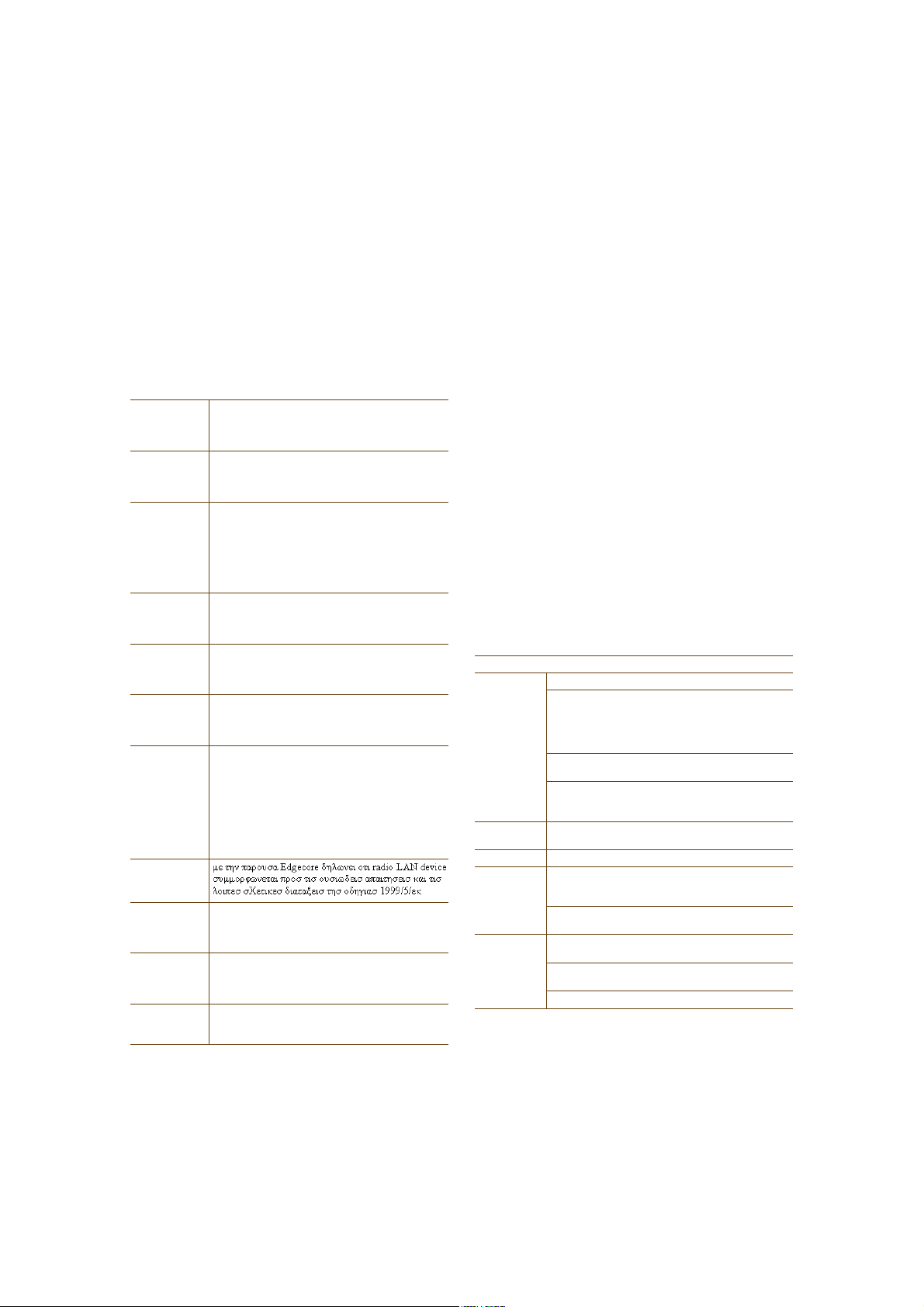
direction. Omnidirectional antennas create a coverage area that looks like a doughnut, broadcasting to the
sides much more effectively than up or down (see Figure1 on page16). In general, this is good for most office
environments because you have large flat floors. However, it can be a problem in environments with high
ceilings.
Deployment Guide 15
Chapter 1 Preparing for a WLAN Deployment
Figure 1 Omnidirectional Antenna Radiation Pattern
The HiveAP can accommodate external antennas via coaxial jacks on its chassis (see "Antennas" on page28).
The jack is a standard male RP-SMA connector. Various patch, directional, and omnidirectional antennas can be
used to change the coverage pattern. The most common external antennas are patch antennas. These are
directional antennas that provide coverage in a single direction. Most commonly they have a transmission
pattern as shown in Figure2. Based on the gain, the signal will be wide (like the low gain antenna shown on top)
or narrow and long (like the high gain antenna shown on the bottom). Note that the coverage patterns are not
perfect for these antennas and that they often broadcast slightly in other directions than the primary one.
These extra "lobes" can be seen in both of the patterns shown below.
Figure 2 Directional Antenna Patterns
øÞ·®¼Ž- Û§» Ê·»©÷
п¬½¸
ß²¬»²²¿-
The following are some quick hints for deploying access points:
• Standard sheetrock walls and dropped ceilings are the best locations for mounting access points.
• When deploying WLANs in retail stores, doing a site survey at each store is likely to be impractical. It is more
common to run detailed site surveys at a few locations and use the results to set up deployment guidelines for
the remaining sites.
• Be aware of metal-lined firewalls, steel pillars, and other metallic surfaces. RF signals can reflect off metal
surfaces, which can cause unexpected coverage patterns. Also watch out for objects that can block or reflect
signals, such as mirrors, plants, walls, steel doors, elevator shafts, and bathroom stalls.
16 Aerohive
Ô±©»® Ù¿·²
Ø·¹¸»® Ù¿·²
Ø·¹¸»® Ù¿·²

PLANNING
• The quality and performance of a Wi-Fi network is a function of the signal-to-noise ratio. To avoid noise issues,
check the area for common noise generators such as industrial microwave ovens, wireless video cameras,
cordless phones and headsets, and Bluetooth devices. Such devices especially cause interference in the 2.4 GHz
spectrum.
• Plan appropriately for high ceilings. With an omnidirectional antenna, the downward coverage is not great. In
normal office space, the ceilings rarely exceed 15 feet, so this issue does not come up very often. In
environments such as warehouses, where ceilings can be up to 50 feet high, ceiling-mounted access points are
not optimal. It is best to deploy them on non-metallic walls about 10 feet to 15 feet above the floor. If this is
not feasible, using patch antennas can help direct the RF energy downward.
• In high-density or high-capacity environments, placing access points on exterior walls allows for a greater
number of cells inside the building and more capacity. In other deployments, it is recommended that the outer
access points be no farther than 30 feet from the exterior walls to ensure coverage.
Preparing the Wired Network for Wireless
One of the advantages of moving to an Aerohive WLAN is that you do not have to make changes to the underlying
network, such as putting controllers into wiring closets. This can save you considerable time and effort during
installation. However, some network changes might make sense for some deployments. For example, you might
want to add additional VLANs or security settings. This section covers a few of the more common considerations
that IT departments are handling.
• 802.1Q VLANs
HiveAPs can segment users into VLANs if an administrator wants. This decision can be made by a returned
RADIUS attribute or it can be configured as part of a user profile or SSID. Enterprises often set up separate
VLANs for wireless and guest access, so that this traffic is segmented from the rest of the network; however, it
is possible to set up any number of other VLANs for further segmentation. (For an example, see "Example 9:
Creating WLAN Policies" on page126.)
• Firewalls
Depending on the environment, enterprises might use firewalls to segment wired and wireless data. This can be
implemented as a discrete firewall enforcing traffic between VLANs or between ports, or you might use the
stateful firewall that is integrated in HiveOS (the HiveAP operating system).
• RADIUS Authentication
If RADIUS authentication is required, then a RADIUS server must be in place and be able to support the
necessary protocols for wireless—often called 802.1X EAP types: PEAP, EAP-TLS, EAP-TTLS, WEP 8021.x (dynamic
WEP), LEAP, EAP-FAST, and captive web portal authentication using CHAP.
• DNS and DHCP Configuration
If you use the Aerohive HiveManager (see the section on "Operational Considerations" on page18), it is possible
to install HiveAPs without any extra configuration and they will be able to contact HiveManager for
management. If the HiveAPs are linked to a different subnet than the one to which HiveManager is connected,
then you can set either a DHCP option or DNS entry to give the location of HiveManager (see "How HiveAPs
Connect to HiveManager" on page95).
Deployment Guide 17

Chapter 1 Preparing for a WLAN Deployment
OPERATIONAL CONSIDERATIONS
To make your WLAN deployment process as smooth as possible, you should consider more than just the distribution
and installation of access points. You should also consider how you will manage, optimize, and troubleshoot your
WLAN after deployment.
Tuning
Approach building an enterprise WLAN with the same life-cycle approach you would apply to a wired network. After
you deploy the WLAN, revisit key network engineering processes to account for changes in the environment. Watch
for access points that are overloaded or are under utilized, and check for potential dead spots. Furthermore, be
aware that the likely points of failure can change as the environment changes. For example, a neighboring business
might install access points that cause RF interference on your network. You should schedule and perform periodic
walkthroughs to ensure that the design goals of the wireless network continue to be met. The Aerohive HiveManager
provides quick views into how the network is behaving, which HiveAPs are the most heavily loaded, and which have
the most clients.
Troubleshooting
Some of the most common issues that arise after deploying a new wireless network are RF interference, RADIUS
issues, and desktop client issues. The first step in troubleshooting is to look at logs and use debug commands.
Aerohive offers an extensive set of event monitoring and debug tools that you can use through HiveManager, the
Aerohive network management system. For additional troubleshooting, particularly of clients or neighboring
networks, Aerohive recommends two tools: Ethereal Warehouser (http://www.wireshark.org/) and AirMagnet
Laptop Analyzer (http://www.airmagnet.com/products/laptop.htm).
Management
Current Wi-Fi networks typically span an entire company and have complex security policies. Fortunately, the
HiveManager Network Management System makes it simple to manage large networks from a central location. It
provides a single centralized management instance for the entire wireless network. While managed HiveAPs can
operate without HiveManager, it simplifies the provisioning of global policy management and centralized
configuration and monitoring. HiveManager lowers operating costs by speeding deployment, configuration, and
monitoring of the wireless network.
Managing faults and alarms is critical to maintaining uptime. You can view and manage events through HiveManager
logging. Optionally, you can use a third-party tool such as HP OpenView.
HiveManager makes it easy to monitor and troubleshoot HiveAPs within a WLAN infrastructure. HiveManager can
import hierarchical map views that represent the physical location of the network, from the perspective of the
entire world down to the floor level.
Deploying with Confidence
Moving a large enterprise—or even a small one—to a WLAN for the very first time need not be daunting. If you have
moderate experience with LAN deployments of other types and you have taken time to get answers to the important
questions that will affect the network data load, you have every prerequisite for success. The bottom line is to
remember to take stock of your project before you begin to ward against unforeseen costs and performance
bottlenecks. If you have considered the issues and guidelines presented here, you are not far away from a successful
Aerohive WLAN deployment.
18 Aerohive

BASIC WI-FI CONCEPTS
BASIC WI-FI CONCEPTS
The goal of this section is to provide some background on Wi-Fi propagation and how to lay out a wireless network.
While RF (radio frequency) engineering is a rather complicated science, this section provides a simple overview on
the basics of Wi-Fi propagation and channel layout that you need to be able to install an enterprise WLAN.
The first thing to know is that Wi-Fi is forgiving. Wi-Fi tends to transmit a bit farther than you expect, and even in
cases of interference, it tends to just work. This can be both a blessing and a curse. It is a blessing because people
will likely have access to the network, and it is a curse because your overall performance might be suboptimal
without obvious symptoms, like lack of connectivity. Understanding the basics presented in this section will help
ensure a high performance layout.
The first concept to understand is signal strength and how it relates to throughput. Radio power is measured in dBm
(decibels relative to one milliwatt) where 0 dBm = 1 milliwatt, but decibels increase using a log10 math function.
Rather than dusting off your old math books and pulling out your calculator, look at the dBm-to-milliwatt converter
that appears below. Often in Wi-Fi, dBm and milliwatts (mW)—and microwatts ( W)—are used interchangeably. The
following table converts between the two units of measurement.
dBm-to-milliwatt
20 dBm = 100 mW 2 dBm = 1.6 mW
15 dBm = 32 mW 1 dBm = 1.3 mW
10 dBm = 10 mW 0 dBm = 1.0 mW
5 dBm = 3.2 mW -1 dBm = 794 µW
4 dBm = 2.5 mW -5 dBm = 316 µW
3 dBm = 2.0 mW -10 dBm = 100 µW
In RF, there is also a relative measurement that you can use to compare two numbers. This measurement is simply
dB (without the "m"). To see how this concept is applied, consider how radio signal propagation changes over a
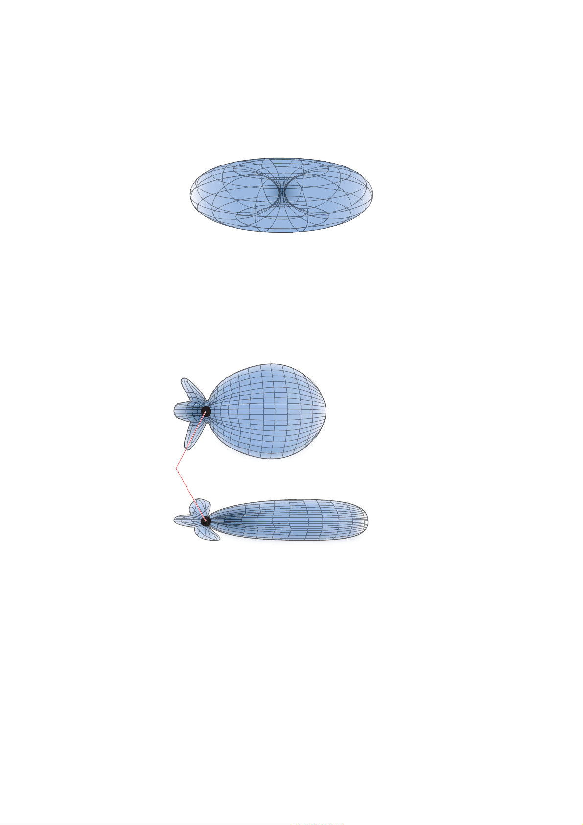
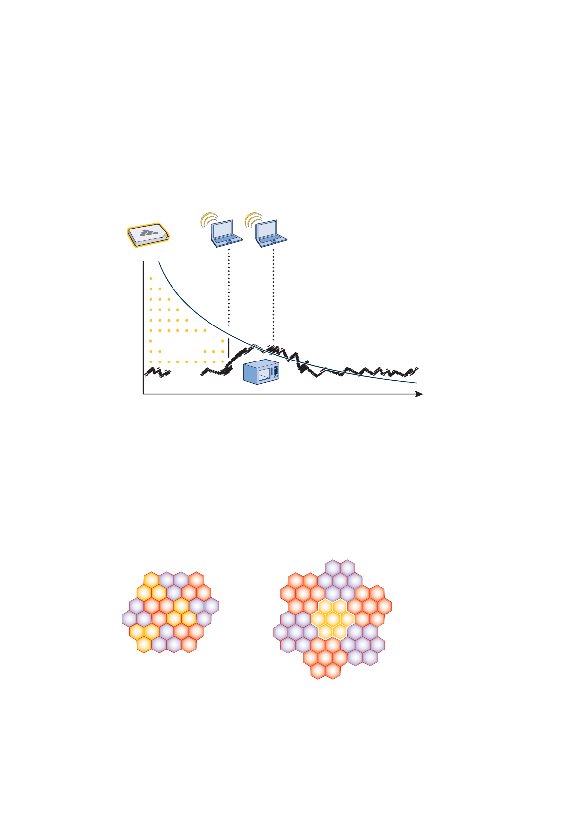
distance and how it can be affected. Figure3 on page20 shows signal strength over distance as a curve that has the
best signal strength closer to the access point. It also shows noise. In general, noise is considered to be low-level
background RF signals that can interfere with a WLAN. This noise tends to be the garbled background RF that comes
from everything from the sun and stars to man-made interfering devices like Bluetooth headsets. It is impossible to
block out noise and it should not be attempted. This low level of background noise is called the "noise floor".
Deployment Guide 19
Chapter 1 Preparing for a WLAN Deployment
Ü·-¬¿²½»
Ü·-¬¿²½»
Figure 3 Path Loss in an Open Space
λ½»·ª»¼ Í·¹²¿´
Í·¹²¿´ó¬±óÒ±·-»
ο¬·±
Ò±·-»
When clients send a packet, the ratio of the signal-to-noise (SNR) level defines the quality of the link, which is
directly related to the performance of the network. Based on the SNR, the client and AP negotiate a data rate in
which to send the packet, so the higher the SNR the better. For good performance, the SNR should be greater than
20 dB, and for optimal performance it should be at least 25 dB.
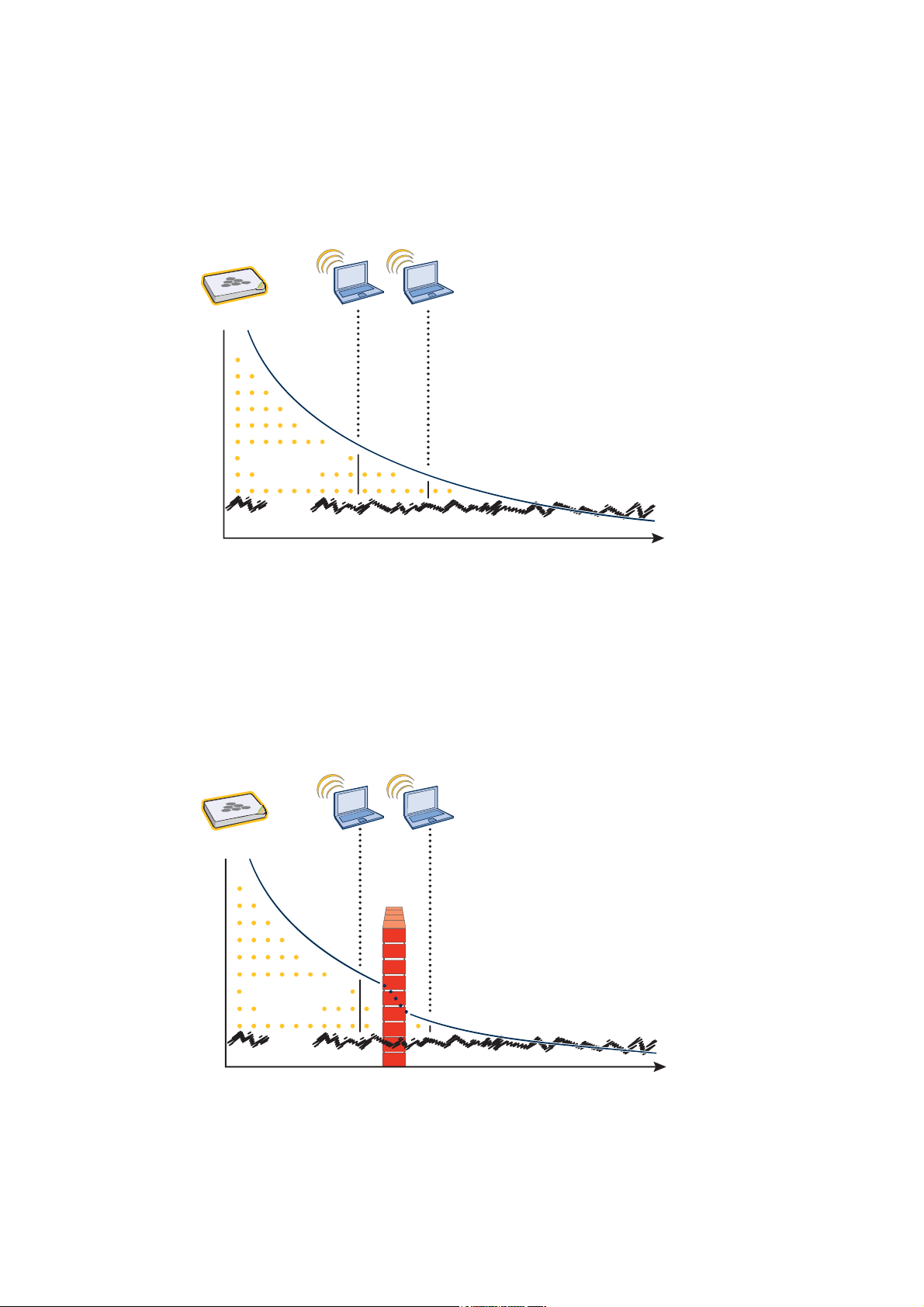
Signal strength not only diminishes over distance but it can also be affected by objects in the way (see Figure4).
This can be a wall, a tree, or even a person. There is a fairly predictable dB drop through most objects that also
decreases the SNR, thus decreasing the data rate. While this appears to be a bad thing, clever Wi-Fi installers use it
to their advantage. It allows them to place more access points in a tighter spot by using pre-existing walls and other
impediments to Wi-Fi propagation to keep them from interfering with each other.
Figure 4 Path Loss through a Wall
λ½»·ª»¼ Í·¹²¿´
É¿´´
Í·¹²¿´ó¬±óÒ±·-»
ο¬·±
Ò±·-»
20 Aerohive
BASIC WI-FI CONCEPTS
Ü·-¬¿²½»
ìð
Microwave ovens, wireless video cameras, Bluetooth headsets, and cordless phones can all interfere with Wi-Fi
signals (see Figure5). Excess noise in an environment is often difficult to diagnose and can have a major negative
impact on network performance. To discover noise sources, a spectrum analysis system is needed. AirMagnet
provides an affordable spectrum analysis tool that operates in the 2.4 GHz and 5 GHz spectra.
Figure 5 Path Loss with Noise (from Microwave)
λ½»·ª»¼ Í·¹²¿´
Í·¹²¿´ó¬±óÒ±·-»
ο¬·±
Ò±·-»
Now that you have a sense of how Wi-Fi performance changes over distance and with noise, look at some ways to
perform channel assignment. If two access points are on the same channel right next to each other, they are forced
to share the same spectrum. This means that they share the 54 Mbps available in 802.11a/g rather than each being
capable of 54-Mbps speeds independently. This essentially halves the bandwidth for each access point. To manage
this situation, make sure that neighboring APs are on different channels and that their power is adjusted so that it
does not overlap that of other APs with the same channel.
In the 2.4 GHz spectrum, there are 11 channels in the United States. However, a Wi-Fi signal consumes more than
one channel. Consequently, there are only 3 non-overlapping channels: 1, 6, and 11. To achieve optimal
performance, you need to design a channel layout pattern such as the one on the left in Figure6.
Figure 6 Channel Layout Patterns
íó¬±óï Ô¿§±«¬ שּׁ»®²
ïï
ïï
ï
êï
ïïï
ê ïïï
ê
ïïê
êï
ïï
ê
ï
ï
ïï
êï
ïïêï
ïïê
êï
ïï
éó¬±óï Ô¿§±«¬ שּׁ»®²
íê
ëî
íê
ìì
íê
ìì
êìêð
êìêð
ëê
ëî
ìð
ëê
ìð
íê
ìì
íê
ìì
êìêð
êìêð
ìì
ëî
êìêð
ëê
ëî
ìð
ëê
ëî
ëê
ìð
ìð
íê
ìì
íê
ìì
êìêð
ëî
êìêð
ëê
ëî
ìð
ëê
Deployment Guide 21
Chapter 1 Preparing for a WLAN Deployment
Note: There are alternative 2.4 GHz channel layouts, such as one for four channels using 1, 4, 8 and 11 and
another using channels 1, 5, 9 to counter interference from microwaves, which tend to cause interference
in the high end of the spectrum. Aerohive recommends alternative channel layouts only for the most
challenging radio environments.
Designing a channel pattern is easier for the 5 GHz spectrum. Depending on the country and the device being used,
there are between 4 and 14 channels available for Wi-Fi use. However, in most countries there are at least 8 to work
with. To simplify the layout of more than 3 channels most use a 7-to-1 pattern, as is shown on the right in Figure6
on page21. This channel layout is much more flexible than the 3-channel system and allows for much better
capacity over all channels.
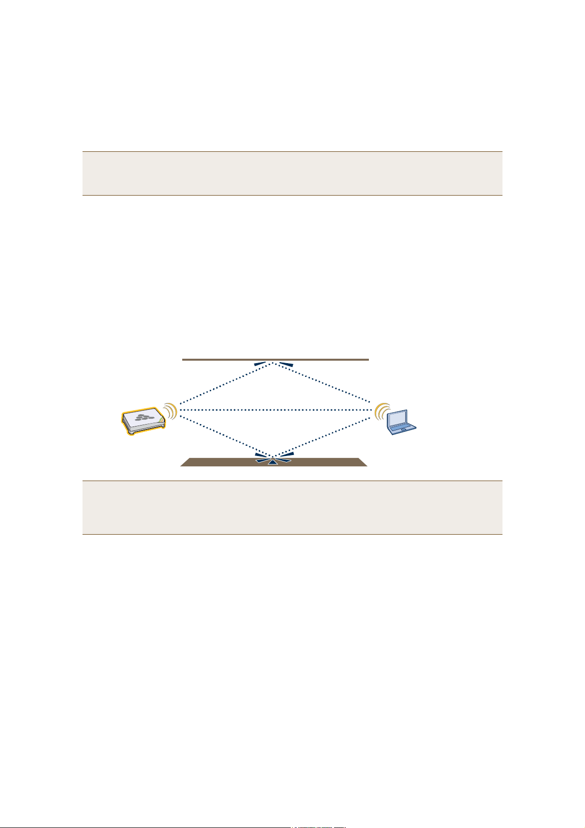
The last topic to cover is the concept of multipaths. When a client receives a transmission from an access point (or
vice versa), the RF signal reaches the client first through a "direct path," but then shortly thereafter by the "indirect
paths" reflected off other objects. The direct path combined with the indirect paths make up multipaths
(see Figure7). RF signals can bounce off of almost anything—walls, people, plants, and so on—but they bounce the
greatest off of metal. As the RF signals bounce about while propagating, one or more of the secondary paths can
interfere with the primary path, causing the signal strength of the direct path to diminish. In doing so, multipath
can greatly decrease signal to noise ratio.
Figure 7 Multipath Radio Waves
Í»½±²¼¿®§ п¬¸
Ю·³¿®§ п¬¸
Í»½±²¼¿®§ п¬¸
Note: If you would like to learn more about how radio frequency propagation works or the details of 802.11,
Wikipedia provides excellent background information under the entries "IEEE 802.11", "radio propagation",
and "multipath". Additionally, spending a few hours with a site survey tool such as AirMagnet Surveyor and
a few test APs can increase both your familiarity with Wi-Fi propagation and your confidence about how it
behaves.
22 Aerohive

Chapter 2The HiveAP 20 ag Platform
The Aerohive HiveAP 20 ag is a new generation wireless access point. HiveAPs have the unique ability to
self-organize and coordinate with each other, creating a distributed-control WLAN solution that offers greater
mobility, security, quality of service, and radio control.
This guide combines product information, installation instructions, and configuration examples for both the HiveAP
and HiveManager platforms. This chapter covers the following topics relating to the HiveAP:
• "HiveAP 20 Product Overview" on page24
• "Ethernet and Console Ports" on page26
• "Status LEDs" on page27
• "Antennas" on page28
• "Mounting the HiveAP 20" on page29
• "Device, Power, and Environmental Specifications" on page31
Deployment Guide 23
 Loading...