

Aerohive
Deployment Guide

Copyright Notice
Copyright © 2007 Aerohive Networks, Inc. All rights reserved.
Aerohive Networks, the Aerohive Networks logo, HiveOS, HiveAP, and HiveManager are trademarks of Aerohive
Networks, Inc. All other trademarks and registered trademarks are the property of their respective companies.
Information in this document is subject to change without notice. No part of this document may be reproduced or
transmitted in any form or by any means, electronic or mechanical, for any purpose, without receiving written
permission from:
Aerohive Networks, Inc.
2045 Martin Avenue, Suite 206
Santa Clara, CA 95050
P/N 330002-01, Rev. A

HiveAP Compliance Information
Federal Communication Commission Interference
Statement
This equipment has been tested and found to comply with the limits for
a Class B digital device, pursuant to Part 15 of the FCC Rules. These
limits are designed to provide reasonable protection against harmful
interference in a residential installation. This equipment generates,
uses and can radiate radio frequency energy and, if not installed and
used in accordance with the instructions, may cause harmful
interference to radio communications. However, there is no guarantee
that interference will not occur in a particular installation. If this
equipment does cause harmful interference to radio or television
reception, which can be determined by turning the equipment off and
on, the user is encouraged to try to correct the interference by one of
the following measures:
• Reorient or relocate the receiving antenna
• Increase the separation between the equipment and receiver
• Connect the equipment into an outlet on a circuit different from
that to which the receiver is connected
• Consult the dealer or an experienced radio/TV technician for help
FCC Caution: Any changes or modifications not expressly approved by
the party responsible for compliance could void the user's authority to
operate this equipment. This device complies with Part 15 of the FCC
Rules. Operation is subject to the following two conditions: (1) This
device may not cause harmful interference, and (2) this device must
accept any interference received, including interference that may
cause undesired operation.
Important: FCC Radiation Exposure Statement
This equipment complies with FCC radiation exposure limits set forth
for an uncontrolled environment. This equipment should be installed
and operated with a minimum distance of 20 centimeters (8 inches)
between the radiator and your body. This transmitter must not be colocated or operating in conjunction with any other antenna or
transmitter.
Wireless 5 GHz Band Statements
High power radars are allocated as primary users (meaning they have
priority) of the 5250-5350 MHz and 5650-5850 MHz bands. These radars
could cause interference and/or damage to the HiveAP when used in
Canada.
The term "IC" before the radio certification number only signifies that
Industry Canada technical specifications were met.
Industry Canada - Class B
This digital apparatus does not exceed the Class B limits for radio noise
emissions from digital apparatus as set out in the interference-causing
equipment standard entitled "Digital Apparatus," ICES-003 of Industry
Canada.
Cet appareil numérique respecte les limites de bruits radioélectriques
applicables aux appareils numériques de Classe B prescrites dans la
norme sur le matérial brouilleur: "Appareils Numériques," NMB-003
édictée par l'Industrie.
EC Conformance Declaration
Marking by the above symbol indicates compliance with the Essential
Requirements of the R&TTE Directive of the European Union (1999/5/
EC). This equipment meets the following conformance standards:
• EN 60950-1 (IEC 60950-1) - Product Safety
• EN 301 893 - Technical requirements for 5 GHz radio equipment
• EN 300 328 - Technical requirements for 2.4 GHz radio equipment
• EN 301 489-1 / EN 301 489-17 - EMC requirements for radio
equipment
Countries of Operation and Conditions of Use in the
European Community
This device is intended to be operated in all countries of the European
Community. Requirements for indoor vs. outdoor operation, license
requirements and allowed channels of operation apply in some
countries as described below.
Note: The user must use the configuration utility provided with this
product to ensure the channels of operation are in conformance with
the spectrum usage rules for European Community countries as
described below.
• This device requires that the user or installer properly enter the
current country of operation in the command line interface as
described in the user guide, before operating this device.
• This device will automatically limit the allowable channels
determined by the current country of operation. Incorrectly
entering the country of operation may result in illegal operation
and may cause harmful interference to other systems. The user is
obligated to ensure the device is operating according to the
channel limitations, indoor/outdoor restrictions and license
requirements for each European Community country as described
in this document.
• This device employs a radar detection feature required for
European Community operation in the 5 GHz band. This feature is
automatically enabled when the country of operation is correctly
configured for any European Community country. The presence of
nearby radar operation may result in temporary interruption of
operation of this device. The radar detection feature will
automatically restart operation on a channel free of radar.
• The 5 GHz Turbo Mode feature is not allowed for operation in any
European Community country. The current setting for this feature
is found in the 5 GHz 802.11a Radio Settings Window as described
in the user guide.
• The 5 GHz radio's Auto Channel Select setting described in the
user guide must always remain enabled to ensure that automatic 5
GHz channel selection complies with European requirements. The
current setting for this feature is found in the 5 GHz 802.11a Radio
Settings Window as described in the user guide.
• This device is restricted to indoor use when operated in the
European Community using the 5.15 - 5.35 GHz band: Channels 36,
40, 44, 48, 52, 56, 60, 64. See table below for allowed 5 GHz
channels by country.
• This device may be operated indoors or outdoors in all countries of
the European Community using the 2.4 GHz band: Channels 1 - 13,
except where noted below.
Deployment Guide 3

HiveAP Compliance Information
– In Italy the end-user must apply for a license from the national
spectrum authority to operate this device outdoors.
– In Belgium outdoor operation is only permitted using the 2.46 -
2.4835 GHz band: Channel 13.
– In France outdoor operation is only permitted using the 2.4 -
2.454 GHz band: Channels 1 - 7.
Operation Using 5 GHz Channels in the European
Community
The user/installer must use the provided configuration utility to check
the current channel of operation and make necessary configuration
changes to ensure operation occurs in conformance with European
National spectrum usage laws as described below and elsewhere in this
document.
Allowed 5 GHz Channels in Each European Community Country
Allowed
Frequency Bands
5.15 – 5.25 GHz*36, 40, 44, 48Austria, Belgium
5.15 – 5.35 GHz*36, 40, 44, 48, 52, 56,
5.15 – 5.35 GHz*
and 5.470 – 5.725
GHz
5 GHz Operation
Not Allowed
* Outdoor operation is not allowed using 5.15 – 5.35 GHz bands
(Channels 36 – 64).
Allowed Channel
Numbers
60, 64
36, 40, 44, 48, 52, 56,
60, 64, 100, 104, 108,
112, 116, 120, 124, 128,
132, 136, 140
NoneGreece
Countries
France, Switzerland,
Liechtenstein
Denmark, Finland,
Germany, Iceland,
Ireland, Italy,
Luxembourg,
Netherlands, Norway,
Portugal, Spain,
Sweden, U.K.
Declaration of Conformity in Languages of the
European Community
EnglishHereby, Edgecore, declares that this Radio LAN
FinnishValmistaja Edgecore vakuuttaa täten että Radio LAN
DutchHierbij verklaart Edgecore dat het toestel Radio
FrenchPar la présente Edgecore déclare que l'appareil
SwedishHärmed intygar Edgecore att denna Radio LAN
DanishUndertegnede Edgecore erklærer herved, at
device is in compliance with the essential
requirements and other relevant provisions of
Directive 1999/5/EC.
device tyyppinen laite on direktiivin 1999/5/EY
oleellisten vaatimusten ja sitä koskevien direktiivin
muiden ehtojen mukainen.
LAN device in overeenstemming is met de
essentiële eisen en de andere relevante bepalingen
van richtlijn 1999/5/EG.
Bij deze Edgecore dat deze Radio LAN device
voldoet aan de essentiële eisen en aan de overige
relevante bepalingen van Richtlijn 1999/5/EC.
Radio LAN device est conforme aux exigences
essentielles et aux autres dispositions pertinentes
de la directive 1999/5/CE.
device står I överensstämmelse med de väsentliga
egenskapskrav och övriga relevanta bestämmelser
som framgår av direktiv 1999/5/EG.
følgende udstyr Radio LAN device overholder de
væsentlige krav og øvrige relevante krav i direktiv
1999/5/EF.
GermanHiermit erklärt Edgecore, dass sich dieser/diese/
Greek
ItalianCon la presente Edgecore dichiara che questo Radio
SpanishPor medio de la presente Manufacturer declara que
PortugueseManufacturer declara que este Radio LAN device
dieses Radio LAN device in Übereinstimmung mit
den grundlegenden Anforderungen und den anderen
relevanten Vorschriften der Richtlinie 1999/5/EG
befindet". (BMWi)
Hiermit erklärt Edgecore die Übereinstimmung des
Gerätes Radio LAN device mit den grundlegenden
Anforderungen und den anderen relevanten
Festlegungen der Richtlinie 1999/5/EG. (Wien)
LAN device è conforme ai requisiti essenziali ed alle
altre disposizioni pertinenti stabilite dalla direttiva
1999/5/CE.
el Radio LAN device cumple con los requisitos
esenciales y cualesquiera otras disposiciones
aplicables o exigibles de la Directiva 1999/5/CE.
está conforme com os requisitos essenciais e outras
disposições da Directiva 1999/5/CE.
Safety Compliance
Power Cord Safety
Please read the following safety information carefully before installing
the HiveAP.
Warning: Installation and removal of the unit must be carried out by
qualified personnel only.
• The unit must be connected to an earthed (grounded) outlet to
comply with international safety standards.
• Do not connect the unit to an A.C. outlet (power supply) without
an earth (ground) connection.
• The appliance coupler (the connector to the unit and not the wall
plug) must have a configuration for mating with an EN 60320/IEC
320 appliance inlet.
• The socket outlet must be near to the unit and easily accessible.
You can only remove power from the unit by disconnecting the
power cord from the outlet.
• This unit operates under SELV (Safety Extra Low Voltage)
conditions according to IEC 60950. The conditions are only
maintained if the equipment to which it is connected also
operates under SELV conditions.
• The PoE (Power over Ethernet), which is to be interconnected with
other equipment that must be contained within the same building
including the interconnected equipment's associated LAN
connections.
France and Peru only:
This unit cannot be powered from IT* supplies. If your supplies are of IT
type, this unit must be powered by 230 V (2P+T) via an isolation
transformer ratio 1:1, with the secondary connection point labelled
Neutral, connected directly to earth (ground).
* Impédance à la terre
Important! Before making connections, make sure you have the correct
cord set. Check it (read the label on the cable) against the following:
4 Aerohive

HIVEAP COMPLIANCE INFORMATION
Power Cord Set
U.S.A.
and Canada
DenmarkThe supply plug must comply with Section 107-2-D1,
SwitzerlandThe supply plug must comply with SEV/ASE 1011.
U.K.The supply plug must comply with BS1363 (3-pin 13 A)
EuropeThe supply plug must comply with CEE7/7
Veuillez lire à fond l'information de la sécurité suivante avant d'installer
le HiveAP.
Avertissement: L'installation et la dépose de ce groupe doivent être
confiés à un personnel qualifié.
• Ne branchez pas votre appareil sur une prise secteur (alimentation
électrique) lorsqu'il n'y a pas de connexion de mise à la terre (mise
à la masse).
• Vous devez raccorder ce groupe à une sortie mise à la terre (mise
à la masse) afin de respecter les normes internationales de
sécurité.
• Le coupleur d'appareil (le connecteur du groupe et non pas la prise
murale) doit respecter une configuration qui permet un
branchement sur une entrée d'appareil EN 60320/IEC 320.
• La prise secteur doit se trouver à proximité de l'appareil et son
accès doit être facile. Vous ne pouvez mettre l'appareil hors
circuit qu'en débranchant son cordon électrique au niveau de
cette prise.
• L'appareil fonctionne à une tension extrêmement basse de
sécurité qui est conforme à la norme IEC 60950. Ces conditions ne
sont maintenues que si l'équipement auquel il est raccordé
fonctionne dans les mêmes conditions.
France et Pérou uniquement:
Ce groupe ne peut pas être alimenté par un dispositif à impédance à la
terre. Si vos alimentations sont du type impédance à la terre, ce groupe
doit être alimenté par une tension de 230 V (2 P+T) par le biais d'un
transformateur d'isolement à rapport 1:1, avec un point secondaire de
connexion portant l'appellation Neutre et avec raccordement direct à la
terre (masse).
Cordon électrique - Il doit être agréé dans le pays d'utilisation
Etats-Unis
et Canada
The cord set must be UL-approved and CSA certified.
Minimum specifications for the flexible cord:
- No. 18 AWG not longer than 2 meters, or 16 AWG
- Type SV or SJ
- 3-conductor
The cord set must have a rated current capacity of at
least 10 A.
The attachment plug must be an earth-grounding
type with NEMA 5-15P (15 A, 125 V) or NEMA 6-15 (15
A, 250 V) configuration.
Standard DK2-1a or DK2-5a.
and be fitted with a 5 A fuse that complies with
BS1362.
The mains cord must be <HAR> or <BASEC> marked and
be of type HO3VVF3GO.75 (minimum).
("SCHUKO").
The mains cord must be <HAR> or <BASEC> marked and
be of type HO3VVF3GO.75 (minimum).
IEC-320 receptacle.
Le cordon doit avoir reçu l'homologation des UL et un
certificat de la CSA.
Les spécifications minimales pour un cable flexible
- AWG No. 18, ou AWG No. 16 pour un cable de
longueur inférieure à 2 mètres.
- Type SV ou SJ
- 3 conducteurs
Le cordon doit être en mesure d'acheminer un
courant nominal d'au moins 10 A.
La prise femelle de branchement doit être du type à
mise à la terre (mise à la masse) et respecter la
configuration NEMA 5-15P (15 A, 125 V) ou NEMA 615P (15 A, 250 V).
DanemarkLa prise mâle d'alimentation doit respecter la section
SuisseLa prise mâle d'alimentation doit respecter la norme
EuropeLa prise secteur doit être conforme aux normes CEE
Bitte unbedingt vor dem Einbauen des HiveAP die folgenden
Sicherheitsanweisungen durchlesen.
Warnung: Die Installation und der Ausbau des Geräts darf nur durch
Fachpersonal erfolgen.
• Das Gerät sollte nicht an eine ungeerdete Wechselstromsteckdose
angeschlossen werden.
• Das Gerät muß an eine geerdete Steckdose angeschlossen werden,
welche die internationalen Sicherheitsnormen erfüllt.
• Der Gerätestecker (der Anschluß an das Gerät, nicht der
Wandsteckdosenstecker) muß einen gemäß EN 60320/IEC 320
konfigurierten Geräteeingang haben.
• Die Netzsteckdose muß in der Nähe des Geräts und leicht
zugänglich sein. Die Stromversorgung des Geräts kann nur durch
Herausziehen des Gerätenetzkabels aus der Netzsteckdose
unterbrochen werden.
• Der Betrieb dieses Geräts erfolgt unter den SELV-Bedingungen
(Sicherheitskleinstspannung) gemäß IEC 60950. Diese Bedingungen
sind nur gegeben, wenn auch die an das Gerät angeschlossenen
Geräte unter SELV-Bedingungen betrieben werden.
Stromkabel. Dies muss von dem Land, in dem es benutzt wird
geprüft werden:
U.S.A.
und
Kanada
DanemarkDieser Stromstecker muß die ebene 107-2-D1, der
SchweizDieser Stromstecker muß die SEV/ASE
EuropeEurope Das Netzkabel muß vom Typ HO3VVF3GO.75
107-2 D1 de la norme DK2 1a ou DK2 5a.
SEV/ASE 1011.
7/7 ("SCHUKO").
LE cordon secteur doit porter la mention <HAR> ou
<BASEC> et doit être de type HO3VVF3GO.75
(minimum).
Der Cord muß das UL gepruft und war das CSA
beglaubigt.
Das Minimum spezifikation fur der Cord sind:
- Nu. 18 AWG - nicht mehr als 2 meter, oder 16 AWG.
- Der typ SV oder SJ
- 3-Leiter
Der Cord muß haben eine strombelastbarkeit aus
wenigstens 10 A.
Dieser Stromstecker muß hat einer erdschluss mit der
typ NEMA 5-15P (15A, 125V) oder NEMA 6-15P (15A,
250V) konfiguration.
standard DK2-1a oder DK2-5a Bestimmungen
einhalten.
1011Bestimmungen einhalten.
(Mindestanforderung) sein und die Aufschrift <HAR>
oder <BASEC> tragen.
Der Netzstecker muß die Norm CEE 7/7 erfüllen
("SCHUKO").
Deployment Guide 5

HiveAP Compliance Information
6 Aerohive

Contents
Chapter 1 The HiveAP Platform................................................................9
Product overview...........................................................................................10
Ethernet and Console Ports......................................................................................12
Status LEDs.........................................................................................................13
Antennas............................................................................................................14
Mounting the HiveAP.......................................................................................15
Device, Power, and Environmental Specifications.....................................................16
Chapter 2 The HiveManager Platform.......................................................17
Product overview...........................................................................................18
Ethernet and Console Ports......................................................................................19
Status LEDs.........................................................................................................20
Rack Mounting the HiveManager..........................................................................21
Device, Power, and Environmental Specifications.....................................................22
Chapter 3 Using HiveManager.................................................................23
Installing and Connecting to the HiveManager GUI....................................................25
Introduction the the HiveManager GUI..................................................................28
Detaching Windows................................................................................................29
Cloning Configurations............................................................................................29
Sorting Displayed Data............................................................................................30
Multiselecting......................................................................................................30
HiveManager Configuration Workflow...................................................................31
Updating HiveAP Firmware................................................................................32
Updating Software on the HiveManager.................................................................33
Chapter 4 HiveManager Examples............................................................35
Example 1: Mapping Locations and Installing HiveAPs................................................37
Setting Up Topology Maps........................................................................................37
Preparing the HiveAPs............................................................................................40
Example 2: Defining Network Objects...................................................................42
Example 3: Defining User Profiles and QoS Settings...................................................45
Example 4: Setting SSID Profiles..........................................................................49
Example 5: Setting Management Service Parameters.................................................52
Deployment Guide 7

Contents
Example 6: Setting AAA RADIUS Settings................................................................55
Example 7: Creating Two Device Groups................................................................57
Example 8: Creating Three Hive Profiles................................................................60
Example 9: Assigning HiveAPs to a Device Group, Radio Profile,
Hive Profile, and Topology Map...........................................................................61
Chapter 5 HiveOS................................................................................65
Common Default Settings and Commands...............................................................66
Configuration Overview....................................................................................67
Device-Level Configurations.....................................................................................67
Policy-Level Configurations......................................................................................68
Chapter 6 Deployment Examples (CLI)......................................................69
Example 1: Deploying a Single HiveAP...................................................................70
Example 2: Deploying a Hive..............................................................................73
Example 3: Using IEEE 802.1X Authentication..........................................................78
Example 4: Applying QoS..................................................................................81
CLI Commands for Examples..............................................................................87
Commands for Example 1........................................................................................87
Commands for Example 2........................................................................................87
Commands for Example 3........................................................................................88
Commands for Example 4........................................................................................89
8 Aerohive

Chapter 1The HiveAP Platform
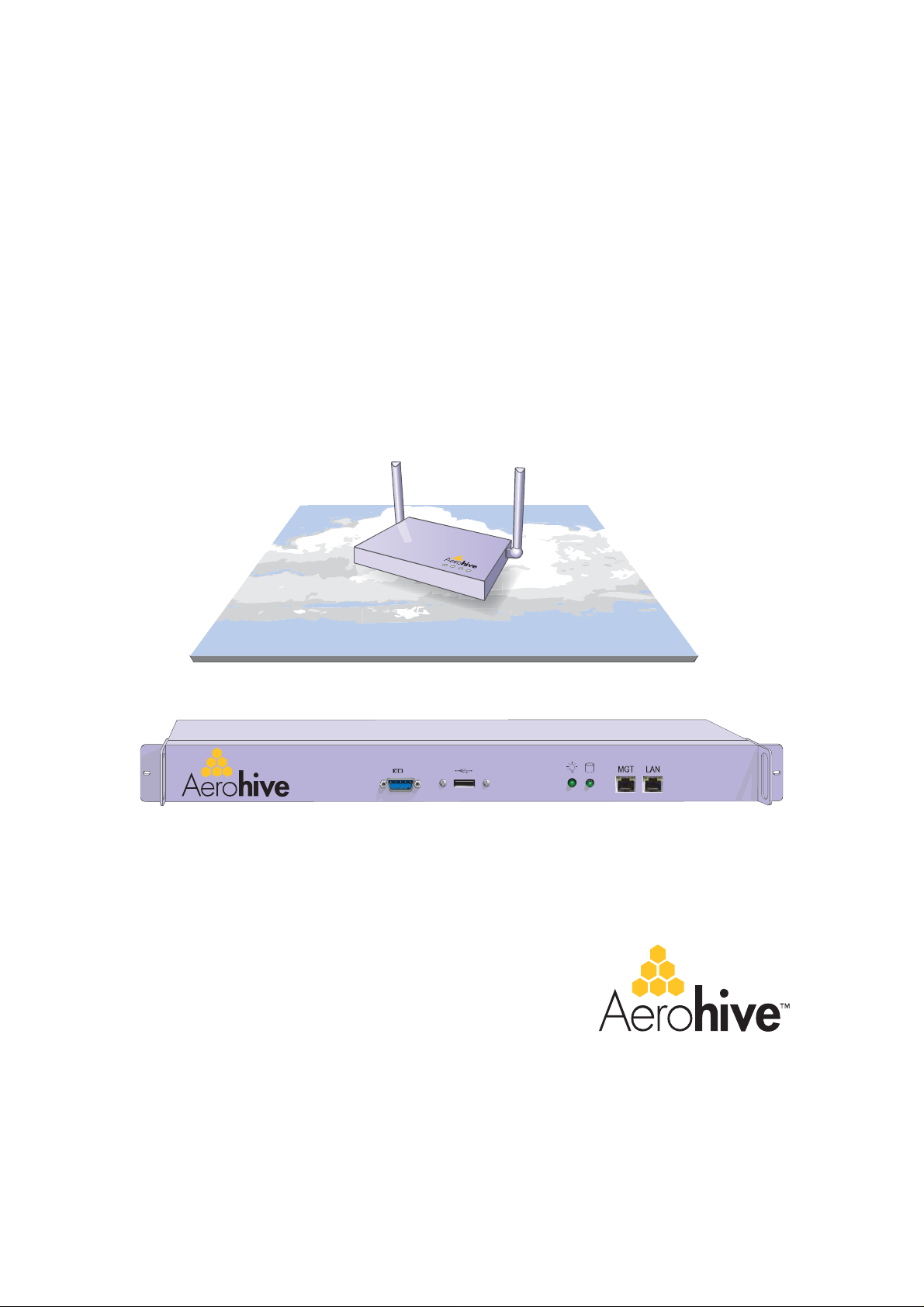
The Aerohive HiveAP 20 ag is a new generation wireless access point. HiveAPs offer unique abilities to self-organize
and coordinate with each other, creating a distributed-control WLAN solution that offers greater mobility, security,
quality of service, and radio control.
This guide combines product information with installation instructions. This chapter covers the following topics:
• "Product overview" on page10
• "Ethernet and Console Ports" on page12
• "Status LEDs" on page13
• "Antennas" on page14
• "Mounting the HiveAP" on page15
• "Device, Power, and Environmental Specifications" on page16
Deployment Guide 9
Chapter 1 The HiveAP Platform
PRODUCTOVERVIEW
The HiveAP is a multi-channel wireless AP (access point). It is compatible with IEEE 802.11b/g (2.4 GHz) and IEEE
802.11a (5 GHz) standards and supports a variety of Wi-Fi (wireless fidelity) security protocols, including WPA (Wi-Fi
Protected Access) and WPA2.
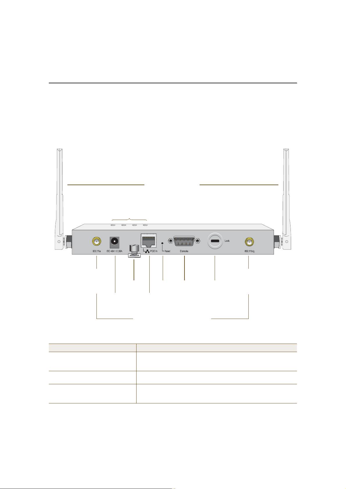
You can see the hardware components on the HiveAP in Figure1. Each component is described in Table1.
Figure 1 HiveAP Hardware Components
Fixed Dual-Band Antennas
Status LEDs
RP-SMA
Connector for
802.11a
Radio Antenna
Connector
Power
Mounting
Screw
10/100 Mbps
Power-over-
Ethernet Port
For Detachable Single-Band Antennas
Reset
Button
Console
Port
Device
Lock Slot
RP-SMA
Connector for
802.11b/g
Radio Antenna
Table 1 HiveAP Component Descriptions
Component Description
Fixed Dual-Band AntennasThe two fixed omnidirectional dipole antennas can operate at either of
the two radio frequencies: 2.4 GHz (for IEEE 802.11b/g) and 5 GHz (for
IEEE 802.11a). For details, see "Antennas" on page14.
Status LEDsThe status LEDs convey operational states for system power, and the LAN,
Access, and Mesh interfaces. For details, see "Status LEDs" on page13.
802.11a RP-SMA Connector(For future use) You can connect a detachable single-band antenna to the
male 802.11a RP-SMA (reverse polarity-subminiature version A)
connector. Note that doing so disables the adjacent fixed antenna.
10 Aerohive

PRODUCTOVERVIEW
Component Description
Power ConnectorThe 48-volt DC power connector (0.38 amps) is one of two methods
through which you can power a HiveAP. To connect it to a 100 – 240-volt
AC power source, use the AC/DC power adaptor that ships with the
product as an option. Because that the HiveAP does not have an on/off
switch, connecting it to a power source automatically powers on the
device.
Mounting ScrewTo mount the HiveAP on a surface, attach the mounting plate that ships
with the product, and then attach the device to the plate by tightening
the mounting screw. For details, see "Mounting the HiveAP" on page15.
10/100 Mbps PoE PortThe 10/100-Mbps Ethernet port supports IEEE 802.3af PoE (Power over
Ethernet) and receives RJ-45 connectors. The HiveAP can receive its
power through an Ethernet connection to power sourcing equipment
(PSE) that is 802.3af-compatible. (If you connect the HiveAP to a power
source through the power connector and PoE port simultaneously, the
device draws power through the power connector and automatically
disables PoE.)
The HiveAP can also connect to the wired network or to a wired device
(such as a security camera) through this port. It is compatible with 10/
100Base-T/TX and automatically negotiates half- and full-duplex
connections with the connecting device. It is autosensing and adjusts to
straight-through and cross-over Ethernet cables automatically. It also
automatically adjusts for 802.3af Alternative A and B methods of PoE.
Reset ButtonThe reset button allows you to reboot the device or reset the HiveAP to
its factory default settings. Insert a paper clip, or something similar, into
the Reset pinhole and press the reset button. To reboot the device, hold
the button down between 1 and 5 seconds. To return the configuration to
the factory default settings, hold it down for at least 5 seconds. After
releasing the button, the Power LED goes dark, and then glows steady
amber while the software loads and the system performs a self-test.
After the software finishes loading, the Power LED glows steady green
Console PortA male DB-9 serial port to which you can make a console connection using
an RS-232 (or "null modem") cable. The management station from which
you make a serial connection to the HiveAP must have a VT100 emulation
program, such as Tera Term Pro© (a free terminal emulator) or Hilgraeve
Hyperterminal® (provided with Windows® operating systems). The
following are the serial connection settings: bits per second:9600, data
bits: 8, parity: none, stop bits: 1, flow control: none.
Device Lock SlotYou can physically secure the HiveAP by attaching a lock and cable (such
as a Kensington® notebook lock) to the device lock slot. After looping the
cable around a secure object, insert the T-bar component of the lock into
the slot on the HiveAP and turn the key to engage the lock mechanism.
802.11b/g RP-SMA Connector(For future use) You can connect a detachable single-band antenna to the
male 802.11b/g RP-SMA connector. Note that doing so disables the
adjacent fixed antenna.
Deployment Guide 11
Chapter 1 The HiveAP Platform
Ethernet and Console Ports
There are two ports on the HiveAP: a 10/100Base-T/TX Ethernet port and a male DB-9 console port. Both ports use
standard pin assignments.
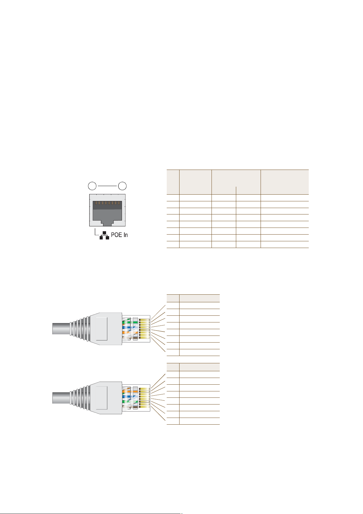
The pin assignments in the PoE (Power over Ethernet) Ethernet port follow the TIA/EIA-568-B standard (see
Figure2). The PoE port accepts standard types of Ethernet cable—cat3, cat5, cat5e, or cat6—and receives power
over this cable from power sourcing equipment (PSE) that is 802.3af-compatible. Such equipment can be embedded
in a switch or router, or it can come from purpose-built devices that inject power into the Ethernet line en route to
the HiveAP. Because the PoE port has autosensing capabilities, the wiring termination in the Ethernet cable can be
either straight-through or cross-over.
Figure 2 PoE Wire Usage and Pin Assignments
Pin Numbers
1 8
(View of the PoE port
on the HiveAP)
The PoE port is auto-sensing and can automatically adjust to transmit and receive data over straight-through or cross-over Ethernet
connections. Likewise, it can automatically adjust to 802.3af Alternative A and B power delivery methods. Furthermore, when the
Alternative A method is used, the PoE port automatically allows for polarity reversals depending on its role as either MDI or MDI-X.
T568A-Terminated Ethernet Cable
with an RJ-45 Connector
T568B -terminated Ethernet Cable
with an RJ-45 Connector
Pin Data Signal MDI MDI-X MDI or MDI-X
1Transmit +DC+DC–– – –
2Transmit -DC+DC–– – –
3Receive +DC– DC+ – – –
4(unused) – – –– – –DC+
5(unused) – – –– – –DC+
6Receive -DC– DC+ – – –
7(unused) – – –– – –DC–
8(unused) – – –– – –DC–
MDI = Medium dependent interface for straight-through connections
MDI-X = Medium dependent interface for cross-over (X) connections
Pin T568A Wire Color
1White/Green
2Green
3White/Orange
4Blue
5White/Blue
6Orange
7White/Brown
8Brown
Pin T568B Wire Color
1White/Orange
2Orange
3White/Green
4Blue
5White/Blue
6Green
7White/Brown
8Brown
802.3af Alternative A
(Data and Power on
the Same Wires)
T568A and T568B are two standard
wiring termination schemes. Note that
the only difference between them is
that the white/green + solid green pair
of wires and the white/orange + solid
orange pair are reversed.
For straight-through Ethernet cables—
using either the T568A or T568B
standard—the eight wires terminate at
the same pins on each end.
For cross-over Ethernet cables, the
wires terminate at one end according
to the T568A standard and at the
other according to T568B.
802.3af Alternative B
(Data and Power on
Separate Wires)
12 Aerohive
PRODUCTOVERVIEW
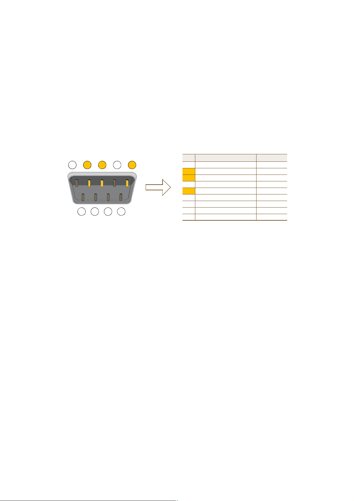
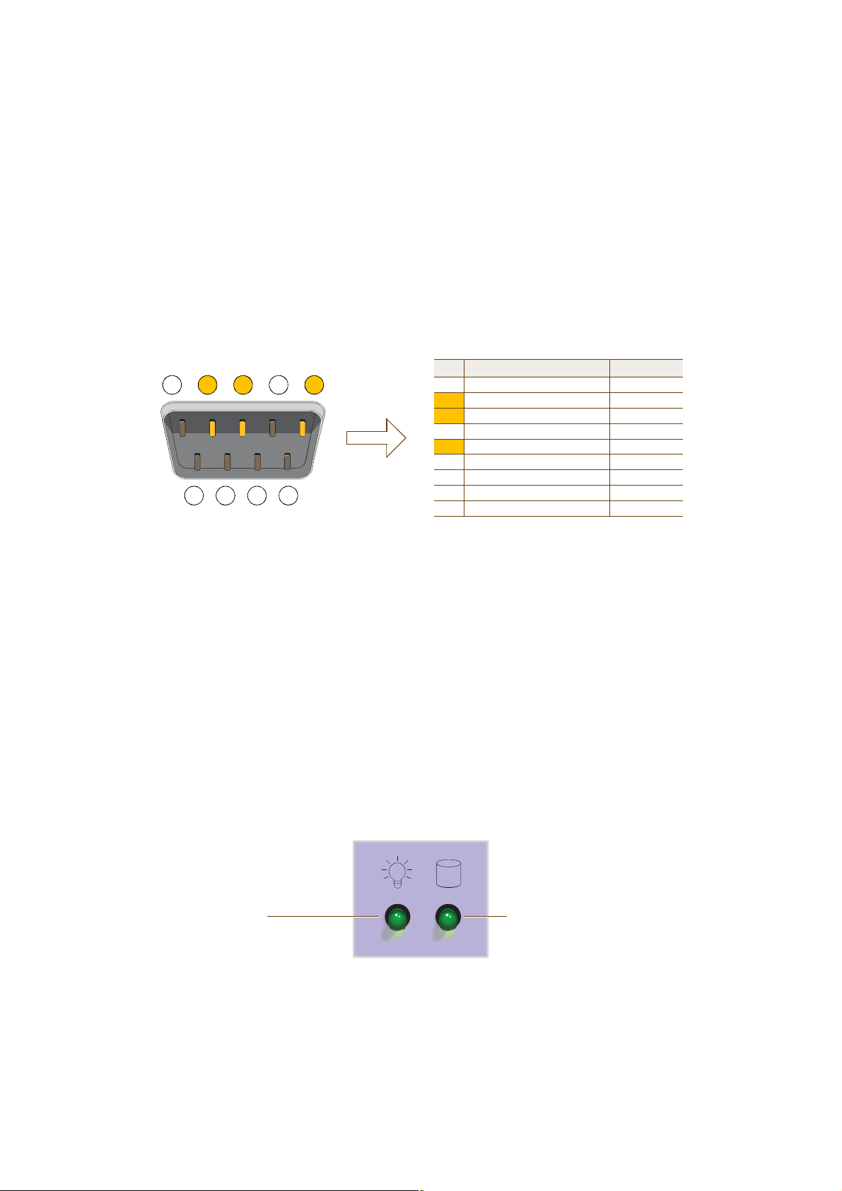
The pin assignments in the male DB-9 console port follow the EIA (Electronic Industries Alliance) RS-232 standard. To
make a serial connection between your management system and the console port on the HiveAP, you can use a null
modem serial cable, use another serial cable that complies with the RS-232 standard, or refer to the pin-to-signal
mapping shown in Figure3 to make your own serial cable. Connect one end of the cable to the console port on the
HiveAP and the other end to the serial (or COM) port on your management system. The management system must
have a VT100 terminal emulation program, such as Tera Term Pro© (a free terminal emulator) or Hilgraeve
Hyperterminal® (provided with Windows® operating systems).
Figure 3 Console Port Pin Assignments
RS-232 Standard Pin Assignments
Male DB-9 Console Port
1 2 3 4 5
6 7 8 9
(View of the console
port on the HiveAP)
Pin Signal Direction
1DCD (Data Carrier Detect)(unused)
2RXD (Received Data)Input
3TXD (Transmitted Data)Output
4DTR (Data Terminal Ready)(unused)
5GroundGround
6DSR (Data Set Ready)(unused)
7RTS (Request to Send)(unused)
8CTS (Clear to Send)(unused)
9RI (Ring Indicator)(unused)
The above pin assignments show a DTE configuration for a
DB-9 connector complying with the RS-232 standard. Because
this is a console port, only pins 2, 3, and 5 need be used.
Status LEDs
The four status LEDs on the top of the HiveAP indicate various states of activity through their color (dark, green,
amber) and illumination patterns (steady glow or blinking). The meanings of the various color + illumination
patterns for each LED is explained below.
Power
• Dark: No power
• Steady green: Powered on and the firmware is running normally
• Steady amber: Firmware is booting up or is being updated
• Blinking amber: Alarm indicating firmware failure
LAN
• Dark: Ethernet link is down or disabled
• Steady green: Ethernet link is up but inactive
• Blinking green: Ethernet link is up and active
Access
• Dark: Wireless link is disabled
• Steady green: Wireless link is up but inactive
• Blinking green: Wireless link is up and active
Mesh
• Dark: Wireless link is disabled
• Steady green: Wireless link is up but inactive
• Blinking green (fast): Wireless link is up and the HiveAP is searching for other hive members
• Blinking green (slowly): Wireless link is up and active
Deployment Guide 13
Chapter 1 The HiveAP Platform
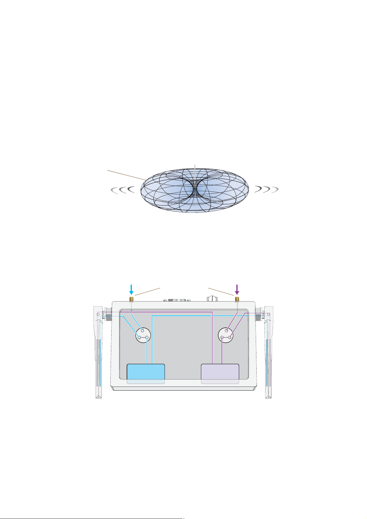
Antennas
The HiveAP includes two fixed dual-band antennas. These antennas are omnidirectional, providing fairly equal
coverage in all directions in a toroidal (donut-shaped) pattern around each antenna. When the antennas are
positioned vertically, coverage expands primarily on the horizontal plane, extending horizontally much more than
vertically. See Figure4, which shows the toroidal pattern emanating from a single vertically positioned antenna. To
change coverage to be more vertical than horizontal, position the antennas horizontally. You can also resize the
area of coverage by increasing or decreasing the signal strength.
Figure 4 Omnidirectional Radiation Pattern
The omnidirectional antennas
radiate equally in all directions,
forming a toroidal pattern.
Note: To show the shape of radiation more clearly,
this illustration depicts the coverage provided by
only one active antenna and is not drawn to scale.
HiveAP
The pair of fixed dual-band antennas can operate at different frequencies concurrently—one antenna at 2.4 GHz
(IEEE 802.11b/g) and the other at 5 GHz (IEEE 802.11a)—and they can also both operate currently at the same
frequency—for example, at 2.4 GHz. Conceptually, the relationship of antennas and radios is shown in Figure5.
Figure 5 Antennas and Radios
\
RP-SMA Connectors
802.11a/b/g
Dual-Band
Fixed
Antenna
Antenna
Switch 1
Antenna
Switch 2
802.11a/b/g
Dual-Band
Fixed
Antenna
Radio 1
RF 802.11b/g
Cut-away view of the HiveAP to show the relationship
of the antennas and the two internal radios.
Radio 2
RF 802.11a
14 Aerohive
MOUNTINGTHE HIVEAP
After connecting an external antenna, you must enter the following command to move subinterfaces from the fixed
antennas to the external antenna:
interface subinterface radio antenna external
where subinterface stems from an interface (wifi0 or wifi1) linked to the radio to which the external antenna
connects: radio 1 (frequency = 2.4 GHz for IEEE 802.11b/g) or radio 2 (frequency = 5 GHz for IEEE 802.11a).
Note that you link interfaces to radios, and subinterfaces to antennas. For example, to link the wifi0 interface to
radio 2, enter this command:
interface wifi0 radio profile name phymode 11a
where radio profile name is a set of previously defined radio parameters. Then, link one of the wifi0.x
subinterfaces to the external antenna connected to radio 2 by using the interface subinterface radio
antenna external command. If you do not enter this command, the subinterface uses the remaining fixed
antenna that remains connected to radio 2 (the external antenna only disables the adjacent fixed antenna).
Note: For information about these and other commands, see the Aerohive CLI Reference Guide.
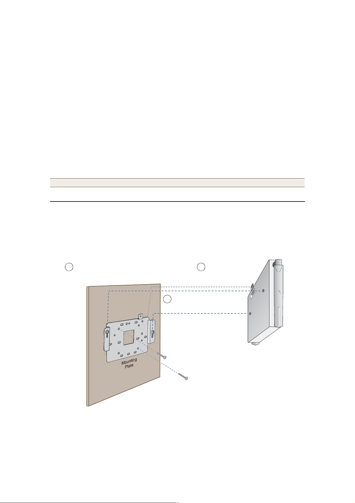
MOUNTINGTHE HIVEAP
You can use the mounting plate to attach the HiveAP to any surface that supports its weight (1.5 lb., 0.68 kg) and to
which you can screw or nail the plate. First, mount the plate to the surface, and then attach the device to the
plate, as shown in Figure6.
Figure 6 Mounting the HiveAP on a Wall
1
With the two wings at the sides of the plate extending
away from the surface, attach the mounting plate to a
secure object such as a wall, ceiling, post, or beam.
3
Use the mounting screw
to secure the HiveAP
to the plate.
2
Insert the pins on the underside
of the HiveAP into the two slots.
Note: There are a variety of holes through which you can
screw or nail the plate in place. Choose the two or three that
best suit the object to which you are attaching it.
Deployment Guide 15

Chapter 1 The HiveAP Platform
DEVICE, POWER, AND ENVIRONMENTAL SPECIFICATIONS
Understanding the range of specifications for the HiveAP is necessary for optimal deployment and operation of the
device. The following specifications describe the physical features and hardware components, the power adapter
and PoE (Power over Ethernet) electrical requirements, and the temperature and humidity range in which the
device can operate.
Device Specifications
• Chassis dimensions: 8 1/4" W x 1" H x 4 15/16" D (21 cm W x 2.5 cm H x 12.5 cm D)
• Weight: 1.5 lb. (0.68 kg)
• Antennas: Two fixed dual-band 802.11a/b/g antennas, and two RP-SMA connectors for detachable single-band
802.11a or 802.11b/g antennas
• Serial port: DB-9 (bits per second:9600, data bits: 8, parity: none, stop bits: 1, flow control: none)
• Ethernet port: autosensing 10/100Base-T/TX Mbps, with IEEE 802.3af-compliant PoE (Power over Ethernet)
Power Specifications
• AC/DC power adapter:
• Input:100 – 240 VAC
• Output: 48V/0.38A
• PoE nominal input voltages: 48 V, 0.35A
• RJ-45 power input pins: Wires 4, 5, 7, 8 or 1, 2, 3, 6
Environmental Specifications
• Operating temperature: 32 to 122 degrees F (0 to 50 degrees C)
• Storage temperature: -4 to 158 degrees F (-20 to 70 degrees C)
• Relative Humidity: Maximum 95%
16 Aerohive

Chapter 2The HiveManager Platform
The HiveManager is a management appliance that provides centralized configuration, monitoring, and reporting for
multiple HiveAPs. The following are a few of the many benefits that a HiveManager offers:
• True "zero configuration" installations of HiveAPs
• Template-based configurations that simplify the deployment of large numbers of HiveAPs
• Scheduled firmware upgrades on HiveAPs by location
• Exportation of detailed information on HiveAPs for reporting
This chapter covers the following topics related to the HiveManager platform:
• "Product overview" on page18
• "Ethernet and Console Ports" on page19
• "Status LEDs" on page20
• "Rack Mounting the HiveManager" on page21
• "Device, Power, and Environmental Specifications" on page22
Deployment Guide 17
Chapter 2 The HiveManager Platform
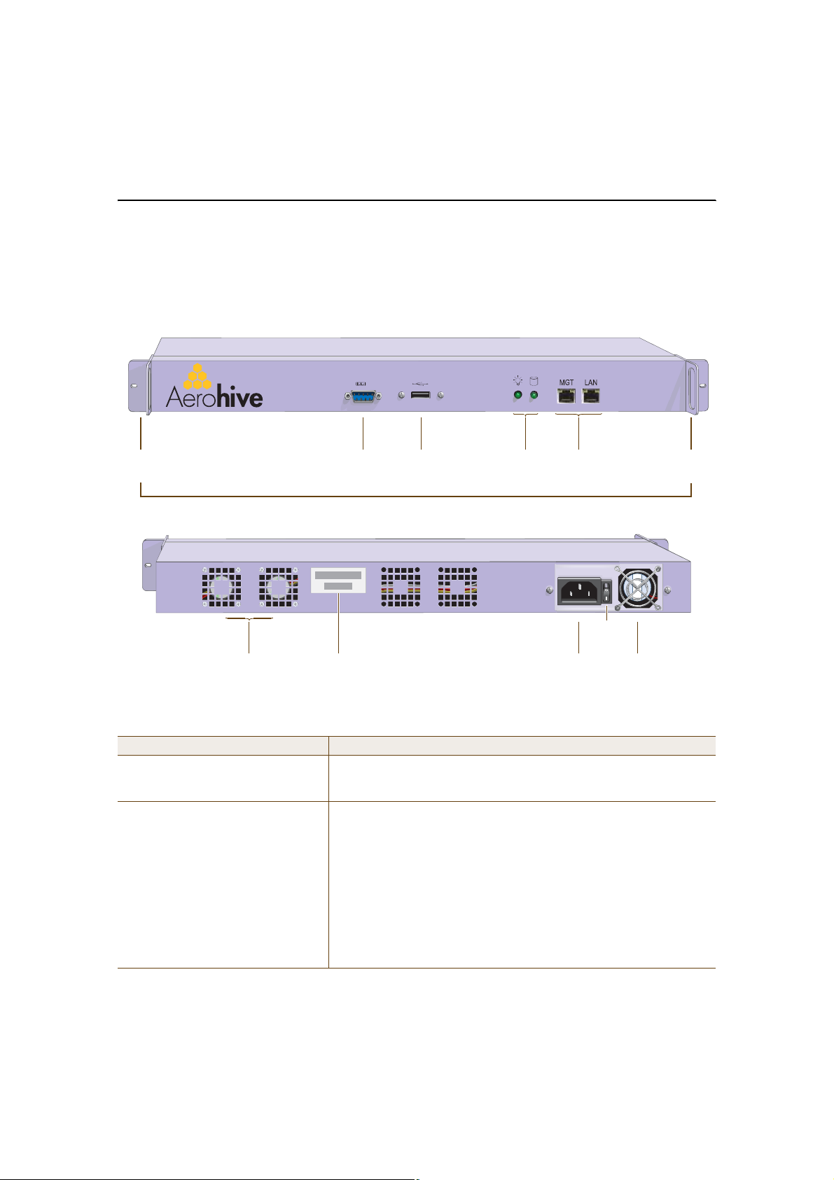
PRODUCTOVERVIEW
The Aerohive HiveManager is a central management system for configuring and monitoring HiveAPs. You can see its
hardware components in Figure1 and read a description of each component in Table1.
Figure 1 HiveManager Hardware Components
Front Panel
Mounting
Bracket
Rear Panel
System
Fans
Console
Port
Serial
Number
USB
Port
Status
LEDs
MGT and LAN
Ethernet Ports
On/Off
Switch
AC Power
Inlet
Mounting
Bracket
Power
Fan
Table 1 HiveManager Component Descriptions
Component Description
Mounting BracketsThe two mounting brackets allow you to mount the HiveManager in a
standard 19" (48.26 cm) equipment rack. You can also move the brackets
to the rear of the chassis if you need to reverse mount it.
Console PortA male DB-9 serial port to which you can make a console connection using
an RS-232 (or "null modem") cable. The pin assignments are the same as
those on the HiveAP (see "Ethernet and Console Ports" on page12).
The management station from which you make a serial connection to the
HiveManager must have a VT100 emulation program, such as Tera Term
Pro© (a free terminal emulator) or Hilgraeve Hyperterminal® (provided
with Windows® operating systems). The following are the serial
connection settings: bits per second:9600, data bits: 8, parity: none, stop
bits: 1, flow control: none. The default login name is root and the
password is aerohive. After making a connection, you can access the
Linux operating system.
18 Aerohive
PRODUCTOVERVIEW
Component Description
USB PortThe USB port is reserved for internal use.
Status LEDsThe status LEDs convey operational states for the system power and hard
disk drive. For details, see "Status LEDs" on page20.
MGT and LAN Ethernet PortsThe MGT and LAN Ethernet ports are compatible with 10/100/1000-Mbps
connections, automatically negotiate half- and full-duplex mode with the
connecting devices, and support RJ-45 connectors. They are autosensing
and automatically adjust to straight-through and cross-over Ethernet
cables. The two ports allow you to separate traffic between the
HiveManager and its administrators from traffic between the
HiveManager and the HiveAPs it manages.
System FansThe two system fans maintain an optimum operating temperature. Be
sure that air flow through the system fan vents is not obstructed.
Serial NumberThe serial number
AC Power InletThe three-prong AC power inlet is a C14 chassis plug through which you
can connect a HiveManager to a 100 – 240-volt AC power source using the
10-amp/125-volt IEC power cord that ships with the product.
On/Off SwitchThe on ( | ) and off ( ) switch controls the power to the HiveManager.
Power FanThe fan that maintains the temperature of the power supply.
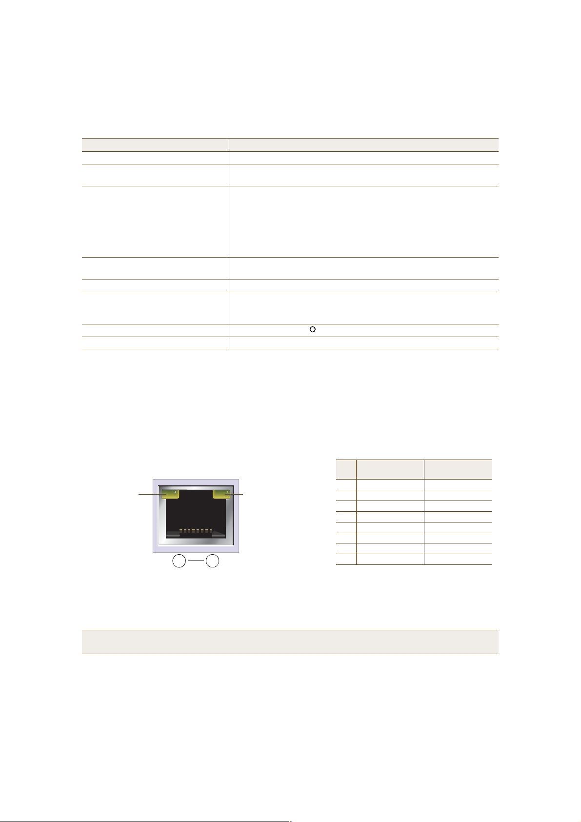
Ethernet and Console Ports
The two 10/100/1000-Mbps Ethernet ports on the HiveManager labeled MGT and LAN use standard RJ-45 connector
pin assignments that follow the TIA/EIA-568-B standard (see Figure2). They accept standard types of Ethernet
cable—cat3, cat5, cat5e, or cat6. Because the ports have autosensing capabilities, the wiring termination in the
Ethernet cables can be either straight-through or cross-over.
Figure 2 Ethernet Port LEDs and Pin Assignments
(View of an Ethernet port
on the HiveManager)
Link Rate LED
Dark: 10 Mbps
Green: 100 Mbps
Amber: 1000 Mbps
Link Activity LED
Dark: Link is down
Steady amber: Link is up
but inactive
Blinking amber: Link is up
and active
8 1
Pin Numbers
The Ethernet ports are auto-sensing and can automatically adjust to transmit and receive data over straight-through or cross-over
Ethernet connections. For a diagram showing T568A and T568B wiring, see "Ethernet and Console Ports" on page12.
10/100Base-T
Pin
Data Signal
1Transmit +BI_DA+
2Transmit -BI_DA3Receive +BI_DB+
4(unused)BI_DC+
5(unused)BI_DC6Receive -BI_DB7(unused)BI_DD+
8(unused)BI_DD-
Legend: BI_D = bidirectional
A+/A-, B+/B-, C+/C-, D+/D- = wire pairings
1000Base-T
Data Signal
Note: The default IP address/netmask for the MGT interface is 192.168.2.10/24, and the IP address of the
default gateway is 192.168.2.254. By default, the LAN interface is not configured.
Deployment Guide 19
Chapter 2 The HiveManager Platform
The pin assignments in the male DB-9 console port follow the EIA (Electronic Industries Alliance) RS-232 standard. To
make a serial connection between your management system and the console port on the HiveManager, you can use a
null modem serial cable, use another serial cable that complies with the RS-232 standard, or refer to the
pin-to-signal mapping shown in Figure3 to make your own serial cable. Connect one end of the cable to the console
port on the HiveManager and the other end to the serial (or COM) port on your management system. The
management system must have a VT100 terminal emulation program, such as Tera Term Pro© (a free terminal
emulator) or Hilgraeve Hyperterminal® (provided with Windows® operating systems).
Figure 3 Console Port Pin Assignments
RS-232 Standard Pin Assignments
Male DB-9 Console Port
1 2 3 4 5
6 7 8 9
(View of the console port
on the HiveManager)
Pin Signal Direction
1DCD (Data Carrier Detect)(unused)
2RXD (Received Data)Input
3TXD (Transmitted Data)Output
4DTR (Data Terminal Ready)(unused)
5GroundGround
6DSR (Data Set Ready)(unused)
7RTS (Request to Send)(unused)
8CTS (Clear to Send)(unused)
9RI (Ring Indicator)(unused)
The above pin assignments show a DTE configuration for a
DB-9 connector complying with the RS-232 standard. Because
this is a console port, only pins 2, 3, and 5 need be used.
The serial connection settings are as follows:
• Bits per second: 9600
• Data bits: 8
• Parity: none
• Stop bits: 1
• Flow control: none
Status LEDs
The two status LEDs on the front of the HiveManager indicate various states of activity through their color (dark,
green, amber) and illumination patterns (steady glow or blinking). The meanings of the various color + illumination
patterns for each LED are shown in Figure4.
Figure 4 Status LEDs
System Power
Dark: No power
Steady illumination: Powered on
Hard Disk Drive
Dark: Idle
Blinking: Active
20 Aerohive
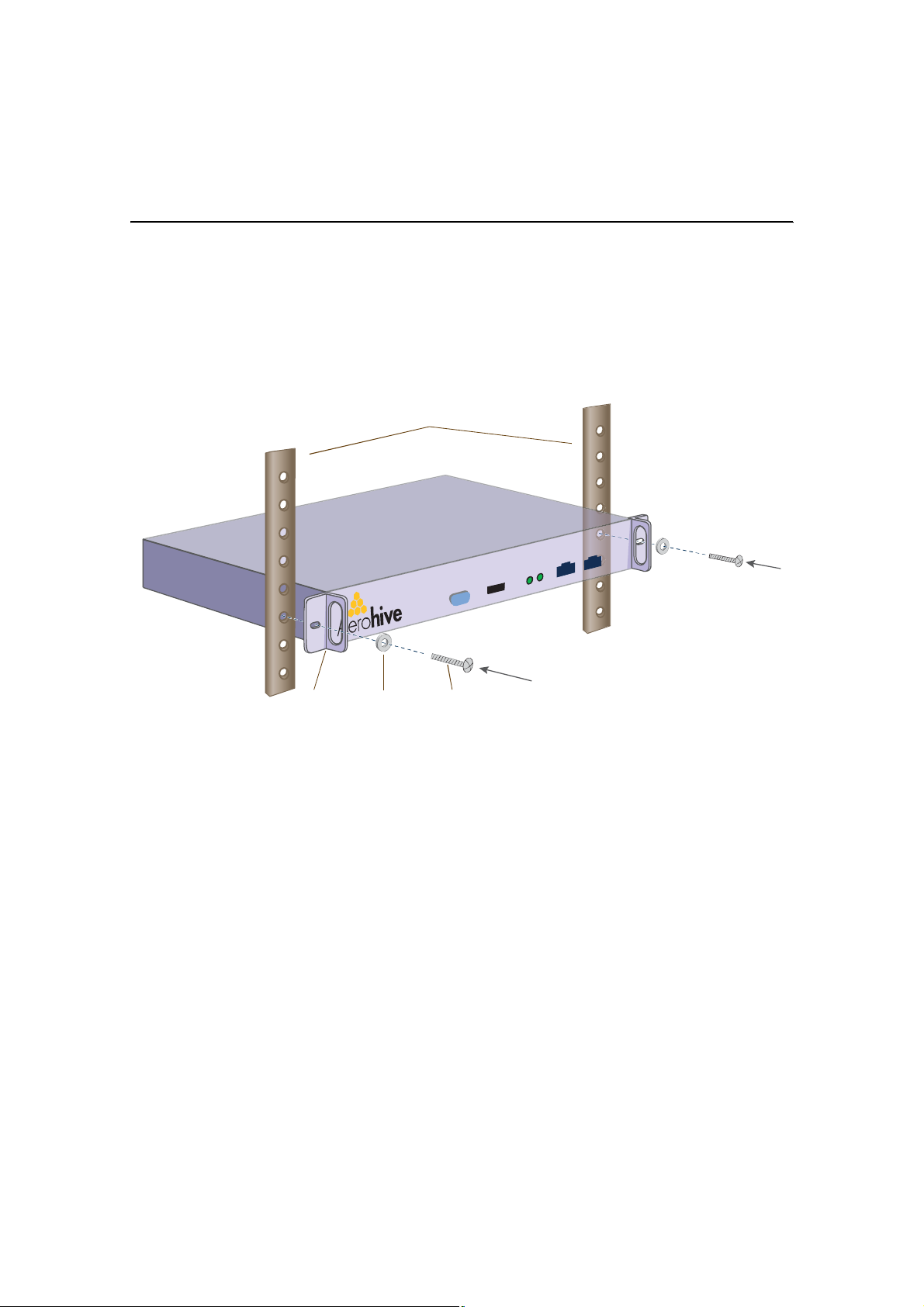
RACK MOUNTINGTHE HIVEMANAGER
RACK MOUNTINGTHE HIVEMANAGER
You can mount the HiveManager in a standard 19" (48 cm) equipment rack with two rack screws—typically 3/4",
1/2", or 3/8" long with 10-32 threads. The HiveManager ships with mounting brackets already attached to its left
and right sides near the front panel (see Figure1 on page18). In this position, you can front mount the HiveManager
as shown in Figure5. Depending on the layout of your equipment rack, you might need to mount the HiveManager in
reverse. To do that, move the brackets to the left and right sides near the rear before mounting it.
Figure 5 Mounting the HiveManager in an Equipment Rack
Rack Rails
Mounting
Bracket
1.Position the HiveManager so that the holes in the mounting brackets align with two mounting holes in the
equipment rack rails.
2.Insert a screw through a washer, the hole in one of the mounting brackets, and a hole in the rail.
3.Tighten the screw until it is secure.
4.Repeat steps 2 and 3 to secure the other side of the HiveManager to the rack.
Deployment Guide 21
WasherRack
Screw

Chapter 2 The HiveManager Platform
DEVICE, POWER, AND ENVIRONMENTAL SPECIFICATIONS
Understanding the range of specifications for the HiveAP is necessary for optimal deployment and operation of the
device. The following specifications describe the physical features and hardware components, the power adapter
and PoE (Power over Ethernet) electrical requirements, and the temperature and humidity range in which the
device can operate.
Device Specifications
• Form factor: 1U rack-mountable device
• Chassis dimensions: 16 13/16" W x 1 3/4" H x 15 13/16" D (42.7 cm W x 4.4 cm H x 40.2 cm D)
• Weight: 13.75 lb. (6.24 kg)
• Serial port: male DB-9 RS-232 port (bits per second:9600, data bits: 8, parity: none, stop bits: 1, flow control:
none)
• USB port: standard Type A USB 2.0 port
• Ethernet ports: MGT and LAN — autosensing 10/100/1000Base-T/TX Mbps
Power Specifications
• ATX (Advanced Technology Extended) autoswitching power supply with PFC (power factor corrector):
• Input: 100 – 240 VAC
• Output: 250 watts
• Power supply cord: Standard three conductor SVT 18AWG cord with an NEMA5-15P three-prong male plug and
three-pin socket
Environmental Specifications
• Operating temperature: 32 to 140 degrees F (0 to 60 degrees C)
• Storage temperature: -4 to 176 degrees F (-20 to 80 degrees C)
• Relative Humidity: 10% – 90% (noncondensing)
22 Aerohive
Chapter 3Using HiveManager
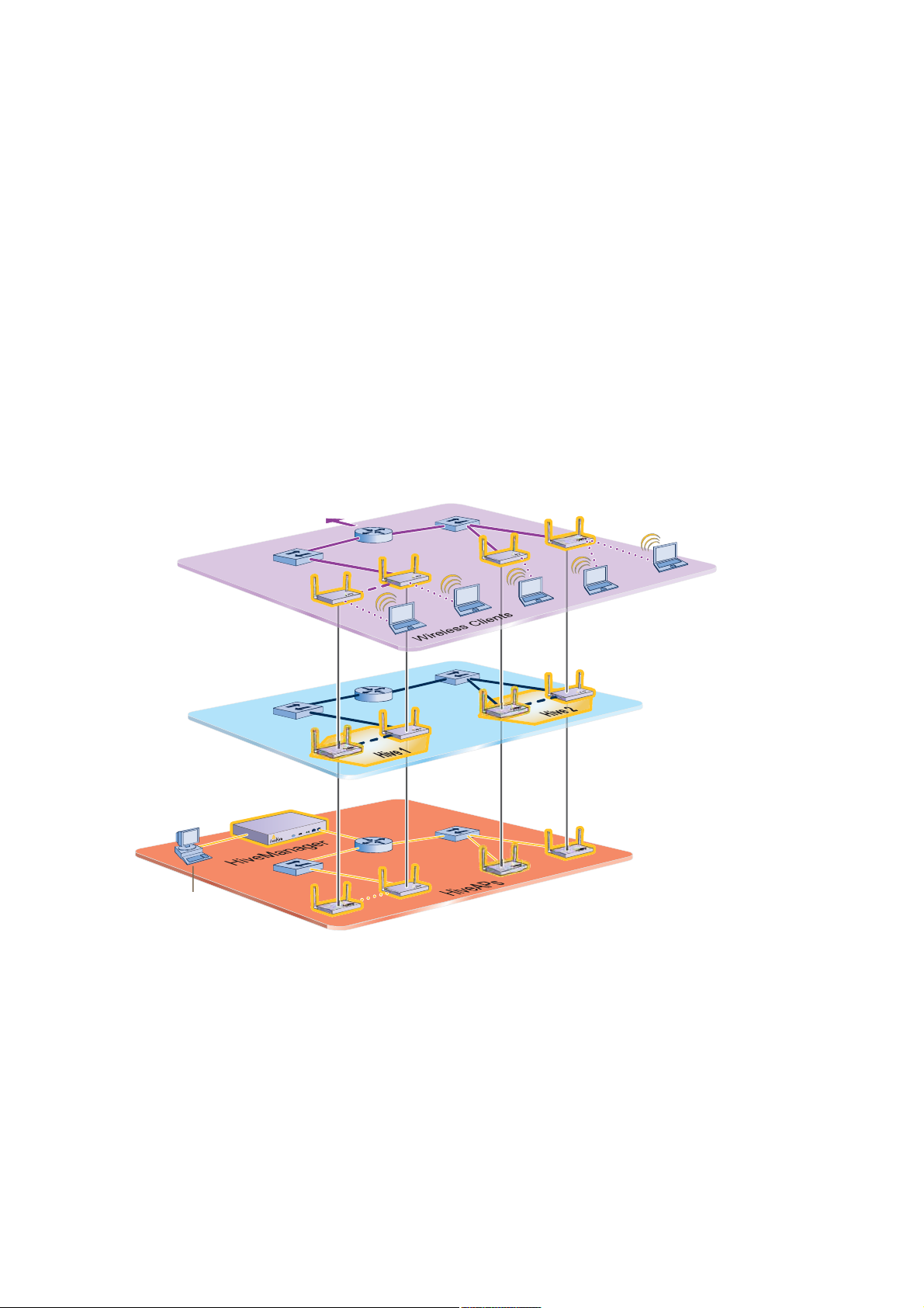
You can conceptualize the Aerohive cooperative control architecture as consisting of three broad planes of
communication. On the data plane, wireless clients gain network access by forming associations with HiveAPs. On
the control plane, HiveAPs communicate with each other to coordinate functions such as best-path forwarding, fast
roaming, and automatic RF (radio frequency) management. On the management plane, the HiveManager provides
centralized configuration, monitoring, and reporting of multiple HiveAPs. These three planes are shown in Figure1.
Figure 1 Three Communication Planes in the Aerohive Cooperative Control Architecture
̱ ¬¸» ©·®»¼
²»¬©±®µ òòò
Ü¿¬¿ д¿²»
©·®»´»-- ½´·»²¬ ¬®¿ºº·½ ø«-»® ¼¿¬¿÷
·- ¬¸» ´±¹·½¿´ ¼·ª·-·±² ±º
¬®¿ª»®-·²¹ ¿ ©·®»´»--ó¬±ó©·®»¼ ÔßÒò Ì®¿ºº·½
·² ¬¸» ¼¿¬¿ °´¿²» º±´´±©- ±°¬·³¿´ °¿¬¸¬¸¿¬ ª¿®·±«- ³»½¸¿²·-³- ·² ¬¸» ½±²¬®±´
°´¿²» ¼»¬»®³·²»ò
̸» ¼¿¬¿ °´¿²»
ݱ²¬®±´ д¿²»
̸» ½±²¬®±´ °´¿²» ·-
̸» ³¿²¿¹»³»²¬
°´¿²» ·- ¬¸» ´±¹·½¿´ ¼·ª·-·±² ±º
Ó¿²¿¹»³»²¬ д¿²»
Ó¿²¿¹»³»²¬
ͧ-¬»³
¬¸» ´±¹·½¿´ ¼·ª·-·±² ±º ¬®¿ºº·½ ¬¸¿¬
¸·ª» ³»³¾»®- «-» ¬± ½±´´¿¾±®¿¬» ±² ¸±©
¾»-¬ ¬± º±®©¿®¼ «-»® ¼¿¬¿ô ½±±®¼·²¿¬»
®¿¼·± º®»¯«»²½·»-ô ¿²¼ °®±ª·¼» ´¿§»®óî
®±¿³·²¹ ½¿°¿¾·´·¬·»- ©·¬¸ »¿½¸ ±¬¸»® ¿²¼
´¿§»®óí ®±¿³·²¹ ½¿°¿¾·´·¬·»- ©·¬¸ ¬¸»
³»³¾»®- ±º ²»·¹¸¾±®·²¹ ¸·ª»-ò
¿¼³·²·-¬®¿¬·ª» ¬®¿ºº·½ ®»´¿¬·²¹ ¬± ¬¸»
½±²º·¹«®¿¬·±² ¿²¼ ³±²·¬±®·²¹ ±º Ø·ª»ßÐ-ò Ú®±³ ¿
³¿²¿¹»³»²¬ -§-¬»³ô ¿² ¿¼³·² ½¿² «-» ¬¸» Ø·ª»Ó¿²¿¹»® ¬±
½±²º·¹«®»ô ³¿·²¬¿·²ô ¿²¼ ³±²·¬±® ³«´¬·°´» Ø·ª»ßÐ-ô »--»²¬·¿´´§ ½±±®¼·ó
²¿¬·²¹ ¬¸» ½±²¬®±´ ¿²¼ ¼¿¬¿ °´¿²»- º®±³ ¿ -·²¹´»ô ½»²¬®¿´ ´±½¿¬·±²ò
As you can see in Figure1, the HiveManager operates solely on the management plane. Any loss of connectivity
between the HiveManager and the HiveAPs it manages only affects HiveAP manageability; such a loss has no impact
on communications occurring on the control and data planes.
Deployment Guide 23

Chapter 3 Using HiveManager
This chapter introduces the HiveManager GUI and explains how to do the following basic tasks:
• Using the console port to change the network settings for the MGT and LAN interfaces
• Powering on the HiveManager and connecting it to a network
• Installing the GUI client on your management system and logging in
It then introduces the HiveManager GUI, including a summary of the configuration workflow. Finally, the chapter
concludes with the procedures for updating HiveAP firmware and HiveManager software. The sections are as
follows:
• "Installing and Connecting to the HiveManager GUI" on page25
• "Introduction the the HiveManager GUI" on page28
• "Detaching Windows" on page29
• "Cloning Configurations" on page29
• "Sorting Displayed Data" on page30
• "Multiselecting" on page30
• "HiveManager Configuration Workflow" on page31
• "Updating HiveAP Firmware" on page32
• "Updating Software on the HiveManager" on page33
24 Aerohive

INSTALLINGAND CONNECTINGTOTHE HIVEMANAGER GUI
INSTALLINGAND CONNECTINGTOTHE HIVEMANAGER GUI
To begin using the HiveManager GUI, you must first configure one or both of its interfaces to be accessible on the
network, put the HiveManager and your management system (that is, your computer) on the network, and then
make an HTTP connection from your system to the MGT port of the HiveManager and download the GUI application
for use with JWS (Java Web Start).
Note: The MGT and LAN interfaces must be in different subnets. The MGT interface is for managing the
HiveManager and the LAN interface is for managing HiveAPs. If you use only one interface for both types of
management traffic, you must use the MGT interface.
Besides the HiveManager and your management system, you need two Ethernet cables and a serial cable (or "null
modem"). The Ethernet cables can be standard cat3, cat5, cat5e, or cat6 cables with T568A or T568B terminations
and RJ-45 connectors. The serial cable must comply with the RS-232 standard and terminate on the HiveManager
end with a female DB-9 connector. (For more details, see "Ethernet and Console Ports" on page19.)
The GUI requirements for the management system are as follows:
• Standard browser that associates JNLP (Java Network Launching Protocol) file types with the Java application
(The Java installation typically makes this association automatically, although not in all UNIX environments.)
• JRE (Java Runtime Environment) version 1.5 or later
• JWS application, which is automatically installed with JRE 1.4.2 or later
• VT100 terminal emulation program, such as Tera Term Pro© (a free terminal emulator) or Hilgraeve
Hyperterminal® (provided with Windows® operating systems)
1
Changing Network Settings for the HiveManager
To be able to connect the HiveManager to the network, you must first set the IP address/netmask of its MGT
interface so that it is in the subnet to which you plan to cable it. To do this, you can use the startup wizard that is
available through the console port.
1.Connect the power cable to a 100 – 240-volt power source, and use the switch on the back panel to turn on the
HiveManager.
2.Connect one end of an RS-232 serial cable to the serial port (or Com port) on your management system.
3.Connect the other end of the cable to the male DB-9 console port on the HiveManager.
4.On your management system, run a VT100 emulation program using the following settings:
• Bits per second (baud rate): 9600
• Data bits: 8
• Parity: none
• Stop bits: 1
• Flow control: none
5.Log in by entering the default user name (root) and password (aerohive).
6.The network startup wizard automatically starts. If not, enter the following command: startupWizard.sh
7.Follow the instructions in the wizard to configure the IP address and netmask for the MGT and LAN interfaces,
as well as the default gateway and host name of the HiveManager and its primary DNS server.
Note: The default IP address/netmask for the MGT interface is 192.168.2.10/24, and the IP address of the
default gateway is 192.168.2.254.
1.JRE 1.5 is basically the same as JRE 5.0. However, JRE 1.5 version names are more granular (1.5.0_01, 1.5.0_02, 1.5.0_03, and
so on). Use JRE 1.5.0_06 or later or the latest version of JRE 5.0.
Deployment Guide 25
Chapter 3 Using HiveManager
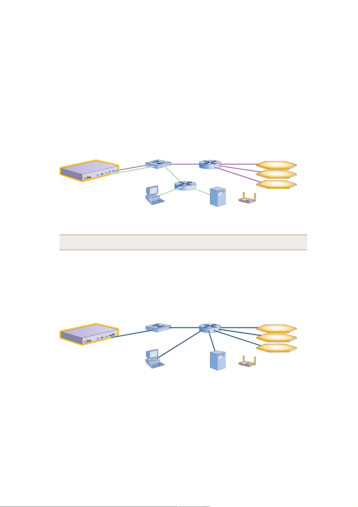
When deciding to use one interface (MGT) or both (MGT and LAN), keep in mind that there are two main types
of traffic to and from the HiveManager:
• HiveManager management traffic for admin access and FTP uploads
• HiveAP management traffic for CAPWAP, SNMP monitoring and notifications, and TFTP configuration and
software downloads
When you enable both interfaces, HiveManager management traffic uses the MGT interface while HiveAP
management traffic uses the LAN interface, as shown in Figure2.
Figure 2 Using Both MGT and LAN Interfaces
пртптктпо
᫬»®
Ø·ª»- ·² ¼·ºº»®»²¬ -«¾²»¬-
пртптнтрсом
пртптмтрсом
пртптлтрсом
Û¿½¸ ¸·ª» ½±²¬¿·²³«´¬·°´» Ø·ª»ßÐ-ò
ÔßÒ
пртптптисом
ÓÙÌ
пртптотисом
Ø·ª»Ó¿²¿¹»®
ß¼³·²
пртптйтнм
Static Routes: The HiveManager sends traffic destined for 10.1.6.0/24 to 10.1.2.1.
The HiveManager sends traffic destined for 10.1.7.0/24 to 10.1.2.1.
Default Gateway:10.1.1.1 (The HiveManager sends traffic here when there are no specific routes to the destination.)
Í©·¬½¸
пртптотп
пртптптп
᫬»®
ÚÌÐ Í»®ª»®
Note: To set static routes after you log in to the GUI, click HiveManager Administration > Network
Configuration, complete the fields in the Route Configuration section, and then click Add.
When only the MGT interface is enabled, both types of management traffic use the same interface. A possible
drawback to this approach is that the two types of management traffic cannot be separated into two different
networks. For example, if you have an existing management network, you cannot use it for the HiveManager
management traffic. Both the HiveManager and HiveAP management traffic would need to flow on the
operational network because the MGT interface would need to be on that network so that the HiveManager
could communicate with the HiveAPs (see Figure3). However, if the separation of both types of traffic is not an
issue, then using just the MGT interface is a simple approach to consider.
Figure 3 Using Just the MGT Interface
пртптктпо
᫬»®
Ø·ª»- ·² ¼·ºº»®»²¬ -«¾²»¬-
пртптнтрсом
пртптмтрсом
пртптлтрсом
Û¿½¸ ¸·ª» ½±²¬¿·²³«´¬·°´» Ø·ª»ßÐ-ò
Í©·¬½¸
ÓÙÌ
пртптптисом
Ø·ª»Ó¿²¿¹»®
ß¼³·²
пртптйтнм
Default Gateway:10.1.1.1 (The HiveManager sends all traffic to the default gateway.)
пртптптп
ÚÌÐ Í»®ª»®
8.After you complete the startup wizard, enter these commands to reboot the software:
stopHiveManager.sh root public
reboot
You can now disconnect the serial cable.
26 Aerohive
INSTALLINGAND CONNECTINGTOTHE HIVEMANAGER GUI
Installing the GUI Client and Connecting to the MGT Interface
1.Connect Ethernet cables from the MGT interface and LAN interface—if you are using it—to the network.
2.Connect an Ethernet cable from your management system to the network so that you can make an Ethernet
connection to the IP address you set for the MGT interface.
3.Open a web browser and enter the IP address of the MGT interface in the address field followed by the
destination port number 9090. For example, if you changed the IP address to 10.1.1.20, enter this in the address
field: http://10.1.1.20:9090
Note: If you ever forget the IP address of the MGT interface and cannot make an HTTP connection to the
HiveManager, make a serial connection to its console port and enter this command: ifconfig. The
output displays data about the MGT interface (internally called "eth0"), including its IP address. For
serial connection settings, see "Changing Network Settings for the HiveManager" on page25.
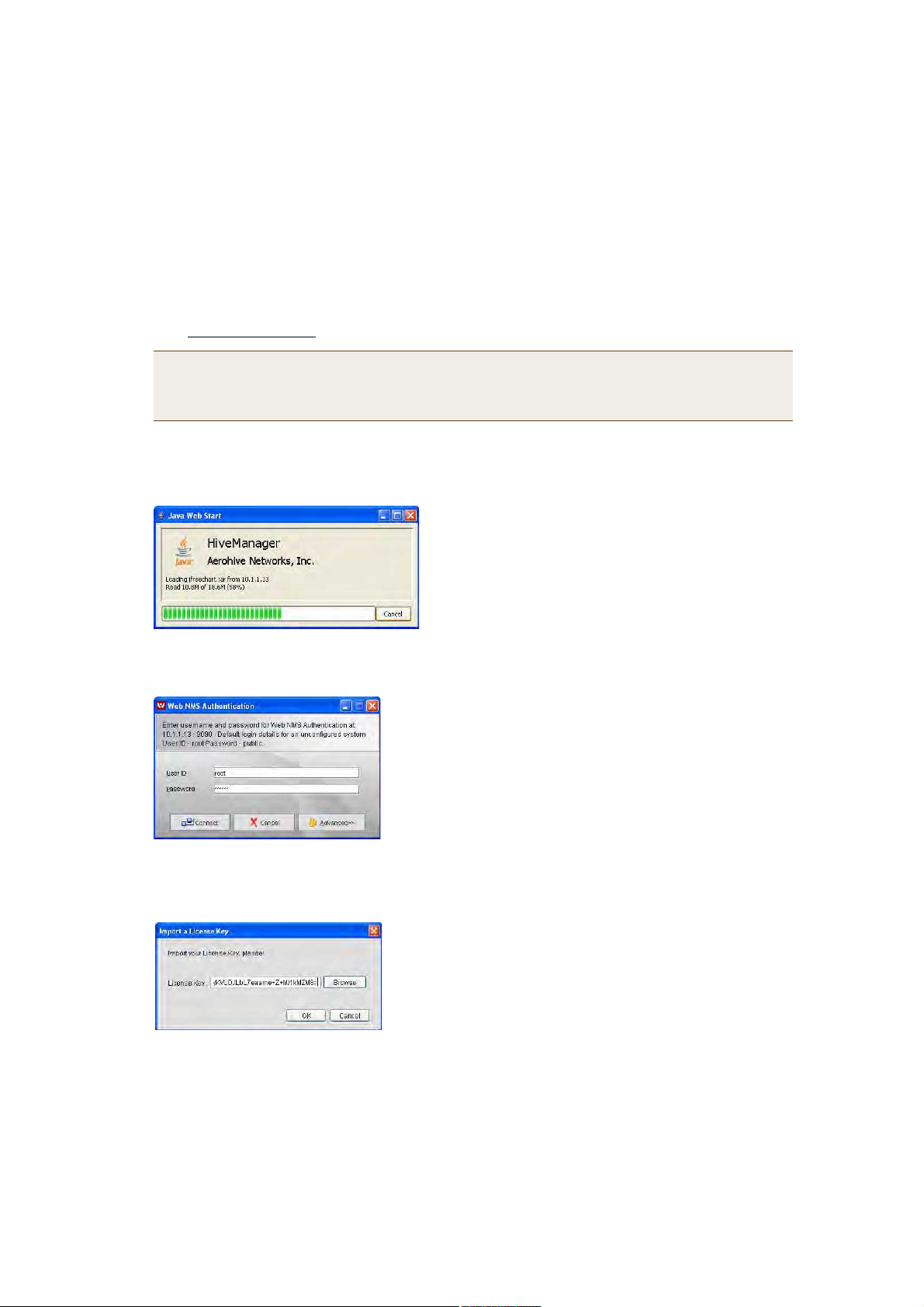
The management system downloads the GUI client software from the HiveManager and installs it in a Java
sandbox. The initial download and installation might take a minute or so to complete, and the web browser
window might appear blank for several seconds at the start. This is normal. After a few seconds, a download
status bar appears onscreen that allows you to monitor the progress of the download and installation.
When the download and installation completes, a login prompt appears.
4.Type the default user name and password (root and aerohive) in the login fields and then click Connect.
The HiveManager GUI application automatically opens and prompts you to enter a license key.
5.Copy the license key string provided by Aerohive when the HiveManager was purchased, paste it in the License
Key field, and then click OK.
You are now logged in to the HiveManager GUI.
Deployment Guide 27

Chapter 3 Using HiveManager
INTRODUCTIONTHETHE HIVEMANAGER GUI
Using the HiveManager GUI, you can set up the configurations needed to deploy large numbers of HiveAPs. The
configuration workflow is described in "HiveManager Configuration Workflow" on page31. The GUI consists of
several important sections, which are shown in Figure4.
Figure 4 Important Sections of the HiveManager GUI
Shortcut Toolbar: The buttons displayed in
this toolbar are for commonly performed
actions. They change as needed to match the
items selected in the menu tree.
Menu Tree: The menu tree provides a
simple method for navigating through the
HiveManager GUI. Items you select in the
menu tree appear in the main window.
Main Window: This is the primary
window in which you set and view
various parameters. You can detach
this window to reposition and resize it.
Alarm Summary View: The HiveManager
displays any alarms detected on managed
HiveAPs here. You can choose one of
three different display options: a table, a
bar chart, or a pie chart.
Some convenient aspects that the HiveManager GUI offers are the ability to detach windows, clone configurations,
sort displayed information, and apply configurations to multiple HiveAPs at once. A brief overview of this
functionality is presented in the following sections.
28 Aerohive
INTRODUCTIONTHETHE HIVEMANAGER GUI
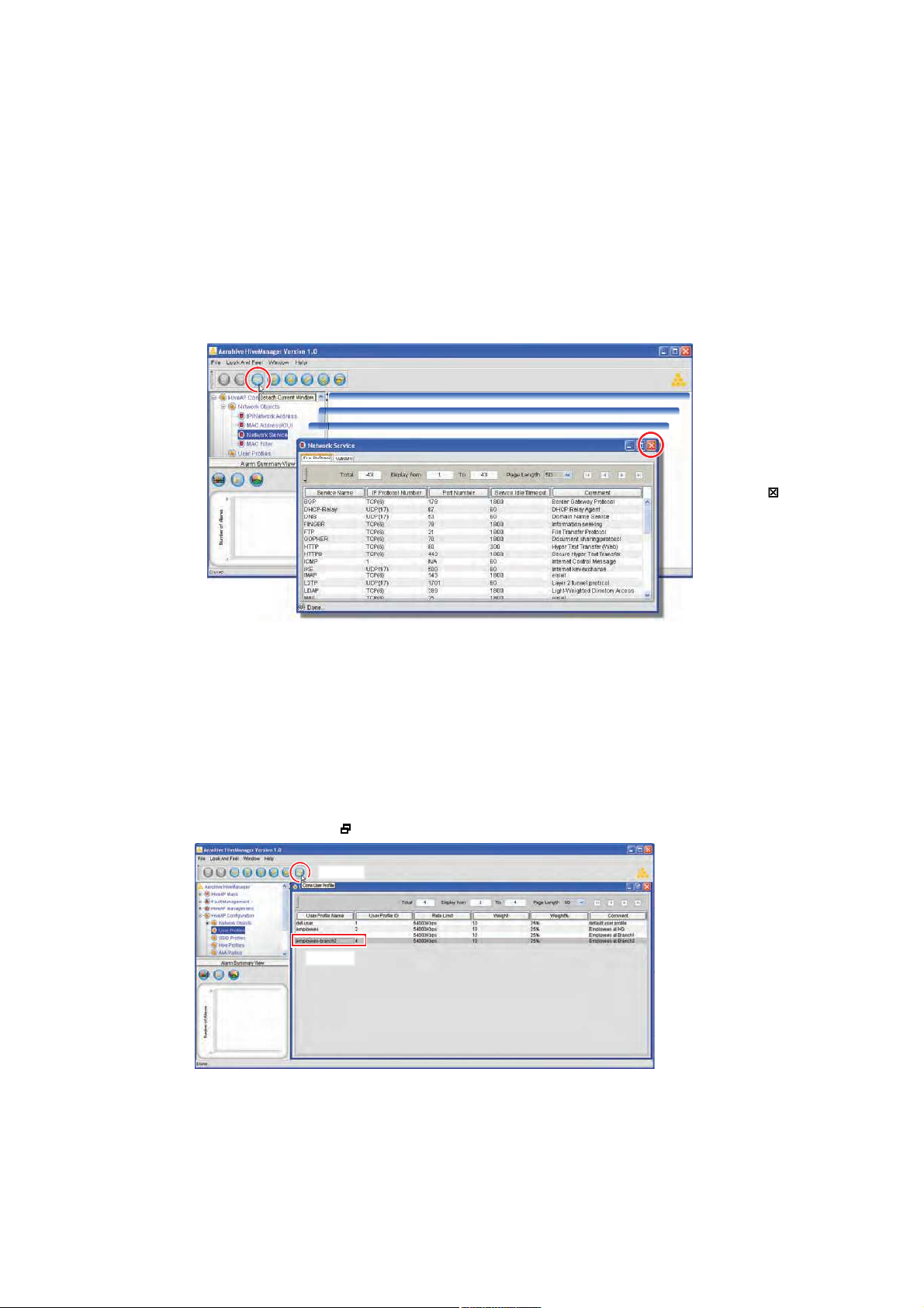
Detaching Windows
When a HiveManager window contains so much information that you cannot display everything you want to see, you
can detach it from the confines of its framed area. Click the Detach Current Window button in the toolbar. Then
you can resize and reshape it to the dimensions you want, essentially customizing your work space.
Figure 5 Detaching the Predefined Services Window
To detach a
window, click
the Detach
button in the
toolbar.
To return a
detached window
to the main window
frame, click the
Close button ( ).
Detach a window and then make it taller or shorter,
wider or narrower, full screen or completely minimized.
Cloning Configurations
When you need to configure multiple similar objects, you can save time by configuring just the first object, cloning
it, and then making slight modifications to the subsequent objects. With this approach, you can avoid re-entering
repeated data.
Figure 6 Cloning a User Profile
To clone an object, select it in the main window, and
then click the Clone button ( ) in the toolbar.
îò Ý´·½µ
ïò Í»´»½¬
Deployment Guide 29
Chapter 3 Using HiveManager
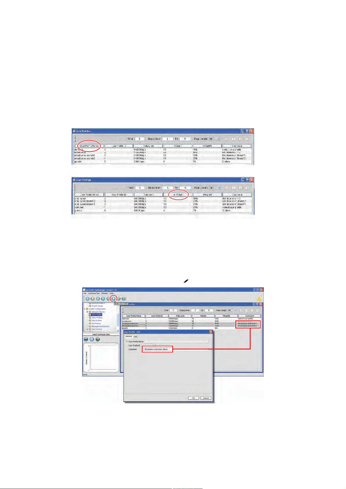
Sorting Displayed Data
You can control how the GUI displays data in the main window by clicking a column header. This causes the
displayed content to reorder itself alphabetically or numerically in either ascending or descending order. Clicking
the header a second time reverses the order in which the data is displayed.
Figure 7 Sorting User Profiles by Name and then by Weight
By default, displayed objects are sorted alphabetically by name.
By clicking the heading of a column, you can reorder the display of objects either alphabetically or
numerically, depending on the content of the selected column. Here you reorder the data by weight.
Multiselecting
You can select multiple objects to make the same modifications to all of them at one time.
Figure 8 Selecting Two User Profiles to Change the Comment
Shift-click to select multiple contiguous objects or control-click to select multiple
noncontiguous objects. Then click the Modify button ( ) in the toolbar.
The changes you make in the Edit User
Profile dialog box apply to both of the
selected user profiles. Here, you are
changing the comment.
30 Aerohive
HIVEMANAGER CONFIGURATION WORKFLOW
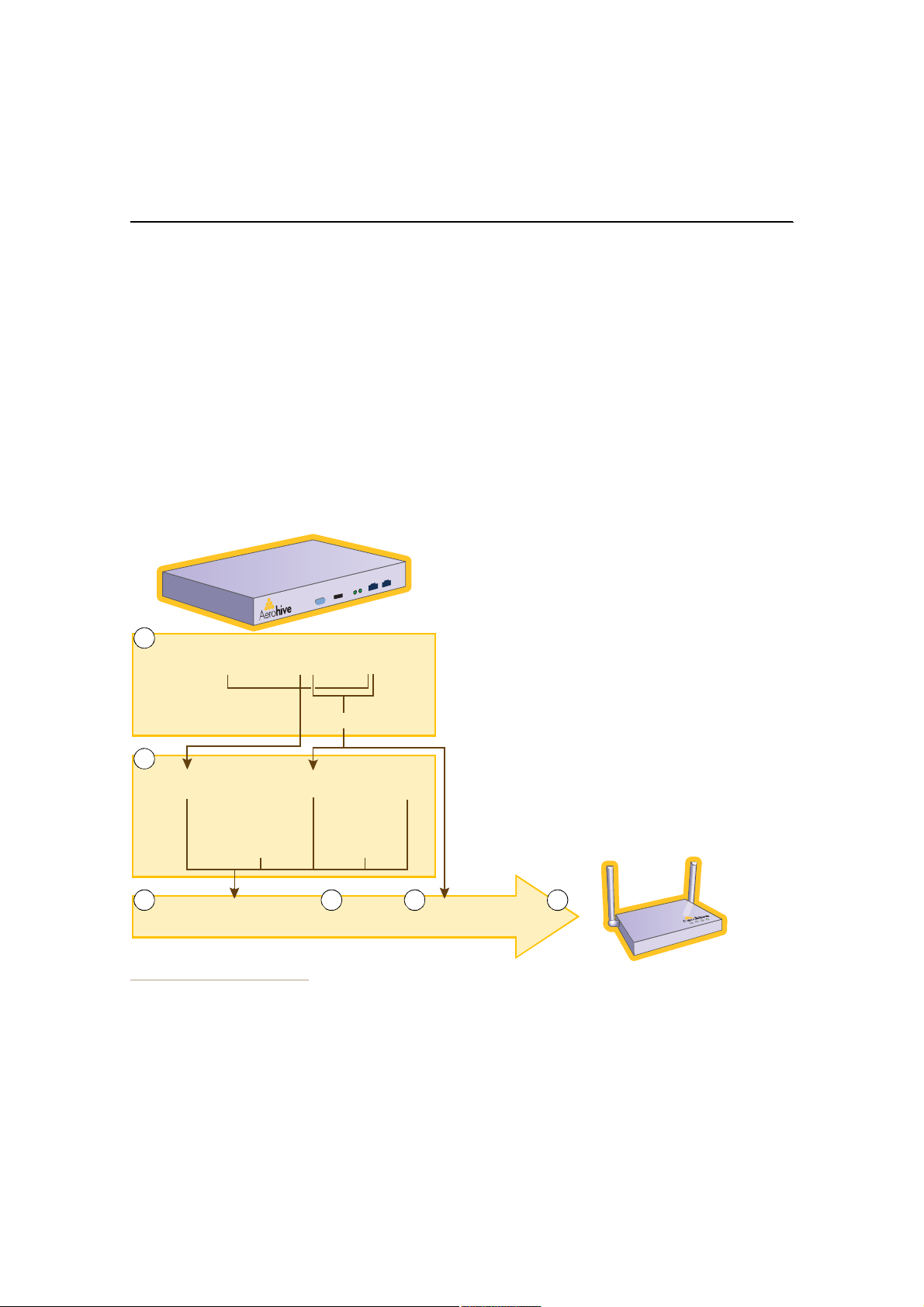
HIVEMANAGER CONFIGURATION WORKFLOW
Assuming that you have already installed your HiveAPs, uploaded maps (see "Setting Up Topology Maps" on page37),
and decided on the features and settings you want them to use, you are now ready to start configuring the HiveAPs
through the HiveManager2. When using the HiveManager to configure HiveAPs, you first define objects that you later
reference when configuring other objects. The typical workflow, shown in Figure9, proceeds like this:
1.Define network objects. You can then reference them when defining QoS traffic classification and marking
settings, SSID profiles, and hive profiles. If you do not plan to use network objects, you can skip this step.
2 and 3.Configure various features and compile them into a device group.
4 and 5.Define radio profiles (or use default settings) and hive profiles. You can define radio profiles at any point in
the configuration process because they do reference any other previously defined object. Similarly, if you do
not make use of MAC filters in the hive profile configuration, you can define those at any point in the process.
6.Assign the device group, radio profile, and hive profile to one or more HiveAPs and then push the configurations
to the physical devices on the network.
Figure 9 Configuration Workflow
1.If you need to reference network objects in QoS traffic
classifications, SSID profiles, and hive profiles, you must define
them first. Otherwise, this step is unnecessary.
2. Use default settings or configure new settings for various
features that, when combined, constitute a device group:
1
Network Objects:
Services, MAC Addresses, MAC OUIs
2
QoS Classification
and Marking
User Profile ID)
User Profiles
(QoS Policy
+
MAC Filters
SSID
Profiles
HiveManager
AAA
Settings
Management
Service Set
(DNS, NTP,
Syslog)
• QoS traffic classification and marking
• User profiles (a combination of QoS policy settings—mainly
traffic forwarding rates and schedules—and a user profile ID)
• SSID profiles
• Management service set (DNS, NTP, and syslog)
• AAA settings (for user authentication using IEEE 802.1X with
RADIUS)
3.Compose a device group by referencing elements set in Step 2.
4.Use default settings or define one or more radio profiles for the
HiveAP to use.
5.Define a hive profile to which the HiveAP will belong.
6.Apply the device group, radio profiles, and hive profile to one or
more HiveAPs, and then push the configurations to the physical
devices across the network.
3 4 5
2.When HiveAPs are in the same subnet as the HiveManager, they can use CAPWAP (Control and Provisioning of Wireless Access
Points) to discover the HiveManager on the network. CAPWAP works within a layer-2 broadcast domain and is enabled by
default on all HiveAPs. If the HiveAPs and HiveManager are in different subnets, then you must configure the DHCP server to
include option 225 in its responses to DHCPDISCOVER and DHCPREQUEST messages from the HiveAPs. This option provides
either the IP address or domain name of the HiveManager. If it provides the domain name, then you must also configure
resource records for the HiveManager on the DNS server that is authoritative for that domain. With this information, the
HiveAPs can contact the HiveManager.
Device Group
(User Profile + SSID + VLAN)
Radio
Profiles
Hive
Profile
6
HiveAP
Deployment Guide 31

Chapter 3 Using HiveManager
UPDATING HIVEAP FIRMWARE
The HiveManager makes it easy to update firmware running on managed HiveAPs. First, you obtain new HiveAP
firmware from Aerohive support and upload it to the HiveManager. Then you push the firmware to the HiveAPs and
activate it by rebooting the HiveAPs.
1.Contact Aerohive support to obtain a new HiveOS image.
2.Save the HiveOS image file to a directory on your local management system or network.
3.Log in to the HiveManager and navigate to HiveAP Management > HiveAP Image .
4.On the HiveAP Image page, enter either of the following—depending on how you intend to upload the HiveOS
image file to the HiveManager—and then click OK:
To load a HiveOS image file from a directory on your local management system:
• Local: (select); type the directory path and image file name, or click Browse, navigate to the image file,
and select it.
To load a HiveOS image file from a TFTP server:
• TFTP IP Address: (select); enter the IP address and port number of the TFTP server (the default port
number for TFTP is 69).
• Image Path: Enter the path to the HiveOS image file. If the file is in the root directory of the TFTP server,
you can leave this field empty.
• Image Name: Type the name of the HiveOS image file.
Note: To delete an old image file, select the file in the Images in existence window, right-click it, and select
Remove from the short-cut menu.
5.Click HiveAP Management > ManagedHiveAPs.
6.In the Managed HiveAPs window, select the HiveAP (or SHIFT-select multiple HiveAPs), right-click, and select
Update > Upload and Activate SW Image.
The Upload Image dialog box appears.
7.Enter the following, and then click OK:
• In the Update column, select the check box for each HiveAP whose software you want to update.
• In the Image List, select the HiveOS image that you want to load on the selected HiveAPs.
• In the Activation Time section, select one of the following options depending on when you want to activate
the software—by rebooting the HiveAPs—after the HiveManager finishes loading it:
• Activate at: Select and set the time at which you want the HiveManager to activate the software.
• Activate now: Select to load the software on the selected HiveAPs and activate it immediately.
• Until next reboot: Select to load the software and not activate it. The loaded software gets activated
the next time the HiveAP reboots.
8.When prompted to confirm the upload operation, click OK.
32 Aerohive

UPDATING SOFTWAREONTHE HIVEMANAGER
UPDATING SOFTWAREONTHE HIVEMANAGER
You can update the software running on the HiveManager from one of three sources: a local directory on your
management system, an FTP server (File Transfer Protocol), or a TFTP (Trivial File Transfer Protocol) server. If you
download an image and save it to a local directory, you can load it from there. If you save the image to an FTP
server, you can direct the HiveManager to connect to the server and upload the file from a subdirectory named
"hm_upgrade" located under the root directory of the FTP user whose name and password you enter in the
HiveManager GUI. If you save the image to a TFTP server, you can direct the HiveManager to log in and load it from
a directory there.
1.Contact Aerohive support to obtain a new HiveManager image.
2.Save the HiveOS image file to a local directory, an FTP server, or a TFTP server.
Note: When using an FTP server, you must save the HiveManager image file in a subdirectory named
"hm_upgrade" directly under the root directory for the FTP user whose user name and password you
enter in the HiveManager. This is unnecessary for TFTP because you can define the directory path and
file name in the HiveManager GUI.
3.Log in to the HiveManager and navigate to HiveManager Administration > Software Upgrade.
Local Directory
To load a HiveOS image file from a directory on your local management system:
1.On the Software Upgrade page, select Local, and type the directory path and software file name; or click
Browse, navigate to the software file, and select it.
2.Click OK (to save the new software and reboot the HiveManager later) or Reset (to reboot the HiveManager with
the new software now).
FTP Server
To load a HiveOS image file from an FTP server:
1.On the Software Upgrade page, select FTP and then enter the following:
• FTP: (select)
• Upgrade Server: Enter the IP address of the FTP server.
• FTP Port: Enter the port number of the FTP server (the default port number for FTP is 21).
• User Name: Enter the user name that the HiveManager must use to log in to the FTP server.
• Password: Enter the password that the HiveManager must use to log in to the FTP server.
After the HiveManager contacts the FTP server, it displays a list of the available image files and prompts you to
choose one.
2.Choose the image file that you want to upload, and then click Finish (to save the new software and reboot the
HiveManager later) or click Reboot (to reboot the HiveManager with the new software now).
Deployment Guide 33

Chapter 3 Using HiveManager
TFTP Server
To load a HiveOS image file from a TFTP server:
1.On the Software Upgrade page, select TFTP, enter the following, and then click OK:
• TFTP IP Address: (select); enter the IP address and port number of the TFTP server (the default port
number for TFTP is 69)
• Image Path: Enter the path to the HiveOS image file. If the file is in the root directory of the TFTP server,
you can leave this field empty.
• Image Name: Type the name of the HiveOS image file.
2.Click Finish to save the new software (without rebooting the HiveManager) or click Reboot to reboot the
HiveManager with the new software now.
Note: For the HiveManager to use the newly loaded image, you must reboot it.
34 Aerohive

Chapter 4HiveManager Examples
The following examples in this chapter show how to install over 70 HiveAPs at three locations in a corporate
network, use the HiveManager to create configurations for them, and then push the configurations to them over the
corporate network. The high-level deployment scheme is as follows:
Headquarters - Building 1 (HQ-B1) Headquarters - Building 2 (HQ-B2) Branch Office (Branch1)
32 HiveAPs32 HiveAPs8 HiveAPs
1 Hive (hive1)1 Hive (hive2)1 Hive (hive3)
1 device group (hq1)1 device group (branch1)
The general design of the deployment is shown in Figure1.
Figure 1 Deployment Overview
¨ è
Ú´±±®-
ШПуЮпШПуЮо
Ø·ª»ï Ø·ª»î
ì Ø·ª»ßÐ-
°»® Ú´±±®
êì
Ø·ª»ßÐ-
̱¬¿´
ݱ®°±®¿¬»
Ø»¿¼¯«¿®¬»®-
Ü»ª·½»Ù®±«°óï
Ø·ª»Ó¿²¿¹»®
ш·² •ШПуЮпŒч
¨ è
Ú´±±®-
ÊÐÒ Ì«²²»´
î Ø·ª»ßÐ-
°»® Ú´±±®
è
Ø·ª»ßÐ-
̱¬¿´
Þ®¿²½¸
Ѻº·½»
¨ ì
Ú´±±®-
Þ®¿²½¸ï
Ø·ª»í
Ü»ª·½»Ù®±«°óî
You can look at any of the following examples individually to study how to configure a specific feature or view all of
them sequentially as a set to study the workflow for deploying large numbers of HiveAPs and configuring them
through the HiveManager.
Deployment Guide 35

Chapter 4 HiveManager Examples
This chapter contains a sequential flow of examples that show how to import and organize maps, configure typically
needed features, assign these features to HiveAPs, and associate HiveAPs with maps. The examples are as follows:
• "Example 1: Mapping Locations and Installing HiveAPs" on page37
Use one of two ways to associate physical HiveAPs with their corresponding icons on topology maps.
• "Example 2: Defining Network Objects" on page42
Define a MAC OUI (organizationally unique identifier) and MAC filter so that QoS classifiers, SSID profiles,
and device groups can reference them. You also map the MAC OUI and several services to Aerohive classes.
• "Example 3: Defining User Profiles and QoS Settings" on page45
Define several user profiles and their companion QoS forwarding rates and priorities.
• "Example 4: Setting SSID Profiles" on page49
Define sets of authentication and encryption services that wireless clients and HiveAPs use when
communicating with each other.
• "Example 5: Setting Management Service Parameters" on page52
Configure DNS, syslog, SNMP, and NTP settings for HiveAPs.
• "Example 6: Setting AAA RADIUS Settings" on page55
Define the AAA RADIUS server connection settings to which HiveAPs send authentication requests.
• "Example 7: Creating Two Device Groups" on page57
Define device groups, which are collections of features defined in previous examples through which HiveAPs
control how wireless clients access the network.
• "Example 8: Creating Three Hive Profiles" on page60
Create hive profiles so that sets of HiveAPs can exchange information with each other over a layer-2
switched network to coordinate client access, provide best-path forwarding, and enforce QoS policies.
• "Example 9: Assigning HiveAPs to a Device Group, Radio Profile, Hive Profile, and Topology Map" on page61
Assign previously defined configurations to detected HiveAPs so that you can begin managing them through
the HiveManager.
36 Aerohive
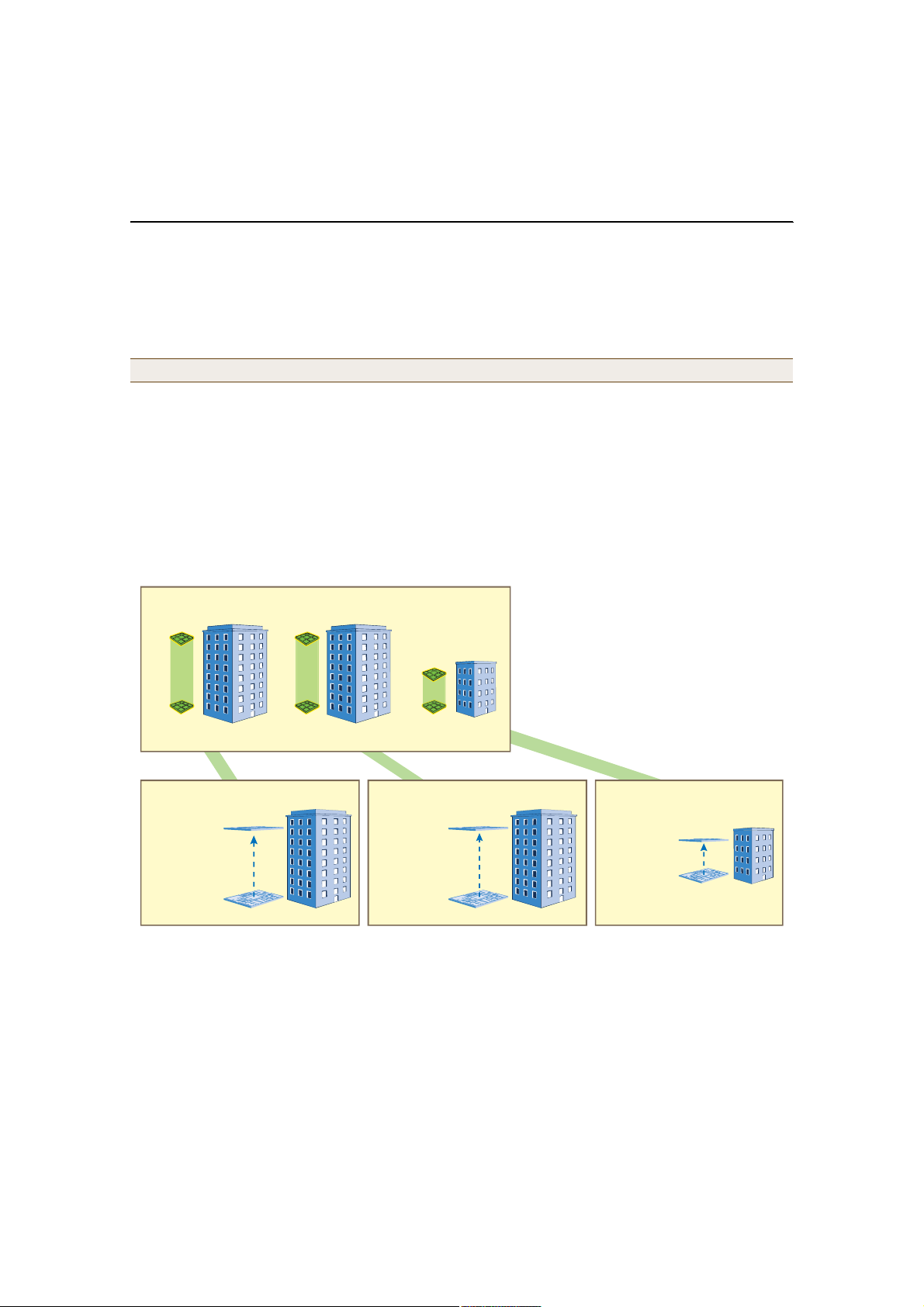
EXAMPLE 1:MAPPING LOCATIONSAND INSTALLING HIVEAPS
The HiveManager allows you to mark the location of HiveAPs on maps that you can then use to track devices and
monitor their status. First, you must upload the maps to the HiveManager, and then name and arrange them in a
structured hierarchy (see "Setting Up Topology Maps"). After that, you can follow one of two ways to install HiveAPs
so that you can later put their corresponding icons on the right maps (see "Preparing the HiveAPs" on page40).
Note: All image files that you upload to the HiveManager must be in PNG (Portable Network Graphics) format.
Setting Up Topology Maps
In this example, you use maps showing the floor plan for each floor in the three office buildings. You need to make
.png files of drawings or blueprints showing the layout of each floor. Also, as an easy means of organizing the maps
in the HiveManager GUI, you create a .png file showing the three buildings HQ-B1, HQ-B2, and Branch-1. By using
this drawing at the top level, you can display icons for each floor of each building. You can then click an icon to link
to its corresponding map. This is shown in Figure2.
Figure 2 Organizational Structure of Level-1 and -2 Maps
Ô»ª»´ ï
̸·- ³¿° -¸±©- í ¾«·´¼·²¹- ¿²¼ îð ·½±²- ¬¸¿¬ ´·²µ ¬± ´»ª»´óî ³¿°-ò
ݱ®°Ñºº·½»- øÔ»ª»´óï Ó¿°÷
Clicking a floor icon on the CorpOffices map
(level 1) opens the corresponding level-2 map.
You can also navigate to any map within the
HiveAP Maps section of the menu tree.
è ·½±²- ´·²µ·²¹
¬± ´»ª»´óî ³¿°-
Ô»ª»´ î
Ш»¿¼¯«¿®¬»®- Ю«·´¼·²¹ п шШПуЮпч У¿°-Ш»¿¼¯«¿®¬»®- Ю«·´¼·²¹ о шШПуЮоч У¿°-Ю®¿²½¸уп У¿°-
•ШПуЮпуЪиŒ
è Ó¿°-
ø±²» °»® º´±±®÷
•ШПуЮпуЪпŒ
è ·½±²- ´·²µ·²¹
¬± ´»ª»´óî ³¿°-
ì ·½±²- ´·²µ·²¹
¬± ´»ª»´óî ³¿°-
•ШПуЮоуЪиŒ
è Ó¿°-
ø±²» °»® º´±±®÷
•ШПуЮоуЪпŒ
•Ю®¿²½¸упуЪмŒ
ì Ó¿°-
•Ю®¿²½¸упуЪпŒ
Uploading Maps
1.Log in to the HiveManager GUI as explained in " Installing and Connecting to the HiveManager GUI" on page25.
2.Click HiveManager Administration > HiveAP Map Setting.
3.In the Upload image to server section of the HiveAP Map Setting window, click Browse, navigate to the
directory containing the .png files that you want to upload, and select one of them.
4.Click Upload to Server.
Deployment Guide 37
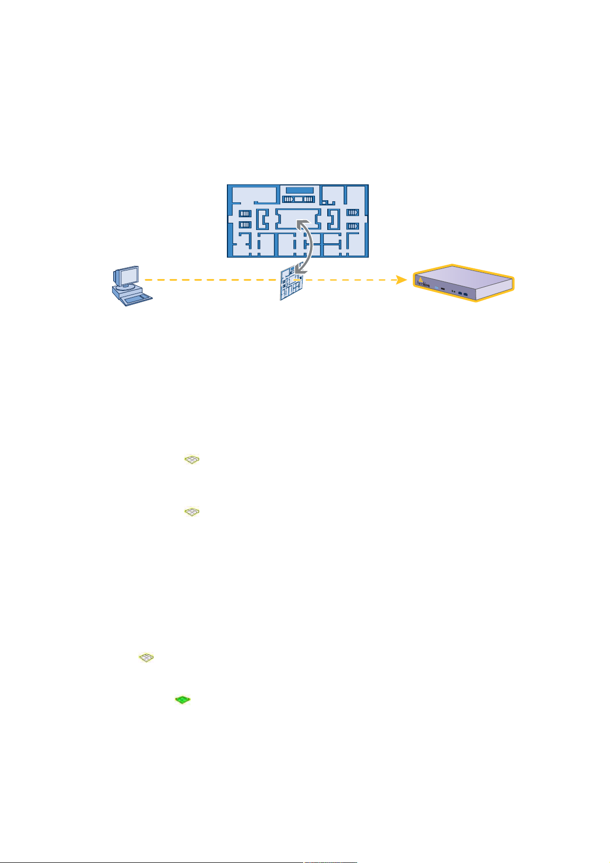
Chapter 4 HiveManager Examples
The selected .png file is transferred from your management system to the HiveManager as shown in Figure3.
Figure 3 Uploading a Map of a Building Floor Plan
Map showing one
of the floor plans
Uploads map to HiveManager
Management System HiveManager
5.Repeat this for all the .png files that you need to load. In this example, you load 21 files:
• 8 maps for the eight floors in HQ-B1 (Headquarters Building 1)
• 8 maps for the eight floors in HQ-B2 (Headquarters Building 2)
• 4 maps for the four floors in Branch-1
• 1 file (named "corp_offices.png" in this example) that shows a picture of the three buildings
6.In the Map level setting section of the HiveAP Map Setting window, enter the following, and then click OK:
• Total Level: 2
• Level 1:
• Level Name: CorpOffices (Note that spaces are not allowed in map level names.)
• Default Icon: floor
• Default Map: Click Browse, select corp_offices.png, and then click Select.
• Level 2:
• Level Name: HQ-B1-F1 (Note that spaces are not allowed in map level names.)
• Default Icon: floor
• Default Map: Click Browse, select HQ-B1-F1.png, and then click Select.
After you click OK, a message appears explaining that you must restart the GUI client for the new settings take
effect.
7.Click File > Exit.
Naming and Arranging Maps within a Structure
1.Launch the GUI client again and log back in
2.Click HiveAP Maps > CorpOffices > Topology > Add Submap.
3.In the Add HQ-B1-F1 dialog box, enter the following, and then click OK:
• Name: HQ-B1-F1
• Icon: floor
• Background Map: HQ-B1-F1.png
• Location: HQ-B1-F1
A green floor icon () labeled "HQ-B1-F1" appears on the CorpOffices image, and a new entry named
"HQ-B1-F1" appears nested under "CorpOffices" in the menu tree.
38 Aerohive

4.Select the icon, drag it to the position where you want it to be, and then click Save.
5.Click HiveAP Maps > CorpOffices > Topology > Add Submap.
6.In the Add HQ-B1-F1 dialog box, enter the following, and then click OK:
• Name: HQ-B1-F2
• Icon: floor
• Background Map: HQ-B1-F2.png
• Location: HQ-B1-F2
A green floor icon () labeled "HQ-B1-F2" appears on the CorpOffices image, and a new entry named
"HQ-B1-F2" appears nested under "CorpOffices" in the menu tree.
7.Select the icon, drag it to the position where you want it to be, and then click Save.
After adding the CorpOffices "map" (really an illustration showing three buildings), two floor plans for the first
and second floors of "HQ-B1", and dragging the floor icons into position, the display of the CorpOffices map
looks similar to that in Figure4.
Figure 4 CorpOffice Map (Level 1) with Links to Level-2 Maps HQ-B1-F1 and HQ-B1-F2
The icons on this map
link to other maps. Click
an icon to open the map
to which it links.
8.Repeat this process until you have arranged all the maps and icons in place as shown in Figure5.
Figure 5 CorpOffice Map with Links to All Level-2 Maps
Deployment Guide 39

Chapter 4 HiveManager Examples
Preparing the HiveAPs
There are several approaches that you can take when mapping the location of installed HiveAP devices. Two
possible approaches are presented below. With the first approach ("Using SNMP"), the HiveManager automatically
assigns HiveAPs to maps. This approach does require a small amount of configuration of each HiveAP up front, but
then the automatic assignment of detected HiveAPs to their appropriate maps on the HiveManager occurs without
any further effort. The second approach ("Using MAC Addresses" on page41) allows you to install HiveAPs without
needing to do any extra configurations, but you later have to match each HiveAP with the right map in the
HiveManager manually.
Using SNMP
This approach makes use of the SNMP (Simple Network Management Protocol) sysLocation MIB (Management
Information Base) object, which you define on a HiveAP. The HiveManager can use this information to associate a
HiveAP with a map and provide a description of where on the map each HiveAP belongs.
1.Make copies of the maps you uploaded to the HiveManager, label them, and take them with you for reference
when installing the HiveAPs.
2.For each HiveAP that you install, do the following:
1.Make a serial connection to the console port, and log in (see "Log in through the console port" on page70).
2.Enter the following command, in which string1 describes the location of the HiveAP on the map (in open
format) and string2 is the name of the map:
snmp location string1@string2
For example, if you install a HiveAP in the northwest corner on the first floor of building 1, enter
snmplocation northwest_corner@HQ-B1-F1. If you want to use spaces in the description, surround
the entire string with quotation marks: snmp location "northwest corner@HQ-B1-F1".
If the name of a map is not unique, then include the map hierarchy in the string until the path to the map is
unique. For example, if you have two maps named "floor-1", and the one you want to use is nested under a
higher level map named "building-1" while the other is nested under "building-2", then enter the command
as follows: snmplocation northwest_corner@floor-1@building-1 . Similarly, if there are two
maps named "building-1" nested under higher level maps for two different sites ("campus-1" and "campus-2",
for example), then include that next higher level in the string to make it unique:
snmplocation northwest_corner@floor-1@building-1@campus-1
3.Mount and cable the HiveAP to complete its installation. (For details, see "The HiveAP Platform" on page9.)
When the HiveManager detects a HiveAP, it checks its SNMP location. When you accept the HiveAP for management,
then the HiveManager automatically associates it with the map specified in its SNMP location description. You can
then click the icon to see its location and then drag it to the specified location on the map. Also, on the HiveAP
Management > New HiveAPs > Automatically discovered page in the HiveManager GUI, you can sort detected
HiveAPs by map name so that you can more easily assign them to device groups, radio profiles, and hive profiles.
40 Aerohive

Using MAC Addresses
With this approach, you write down the MAC address labelled on the underside of each HiveAP and its location while
installing the HiveAPs throughout the buildings. The MAC address on the label is for the mgt0 interface. Because the
MAC addresses of all HiveAPs begin with the Aerohive MAC OUI 00:19:77, you only need to record the last six
numbers in the address. For example, if the MAC OUI is 0019:7700:0120, you only need to write "000120" to be able
to distinguish it from other HiveAPs later.
1.Make copies of the maps you uploaded to the HiveManager, label them, and take them with you when installing
the HiveAPs.
2.When you install a HiveAP, write the last six digits of its MAC address at its location on the map.
When the HiveManager automatically detects HiveAPs, it displays them in the Manage HiveAPs > New HiveAPs >
Automatically Discovered window. You can differentiate them in the displayed list by MAC address, which allows you
to match the HiveAPs in the GUI with those you noted during installation so that you can properly assign each one to
a map, device group, radio profile, and hive profile.
Deployment Guide 41
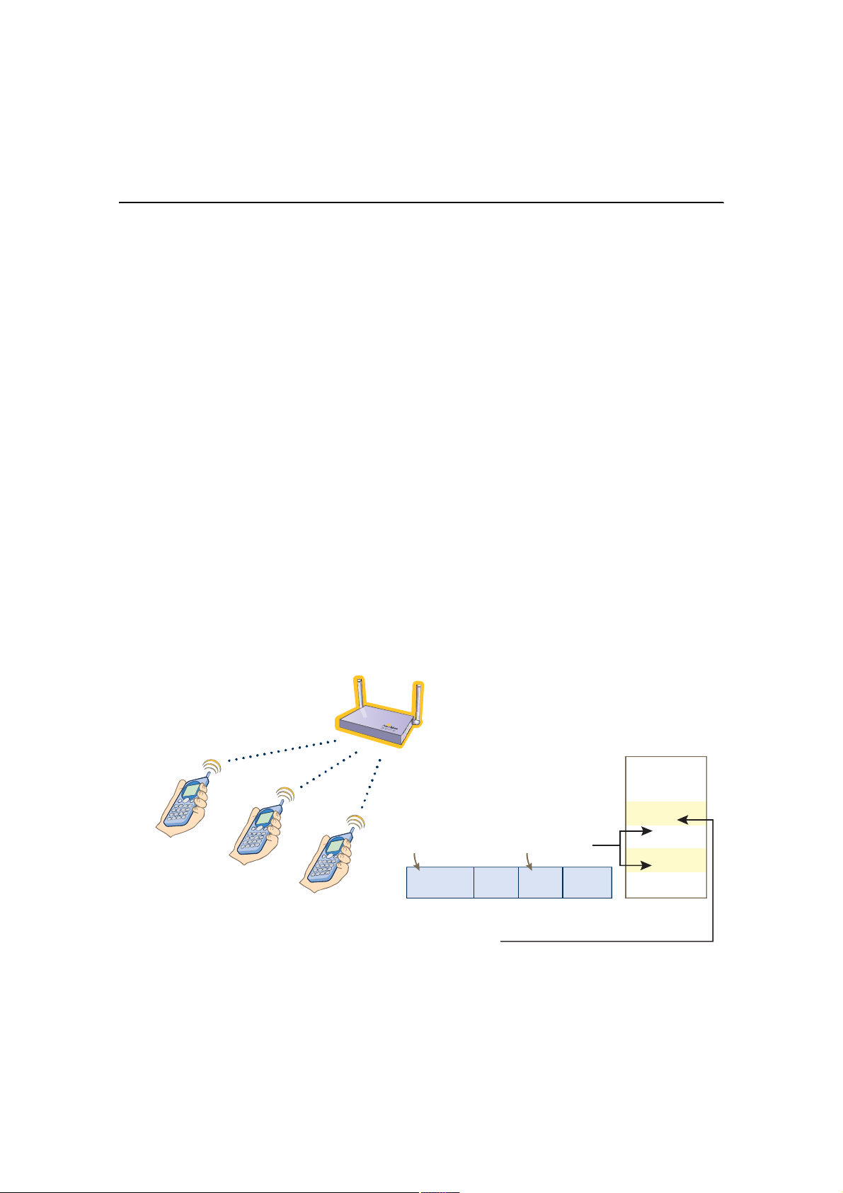
Chapter 4 HiveManager Examples
EXAMPLE 2:DEFINING NETWORK OBJECTS
Network objects are the most basic elements that you can configure through the HiveManager and only function
when other configured items such as QoS classifiers, SSID profiles, and hive profiles make reference to them. IP
addresses, MAC addresses, MAC OUIs (organizationally unique identifiers), and network services (HTTP, SMTP,
FTP, … ) are network objects that make no reference to any other previously defined object. The HiveManager also
classifies MAC filters as a type of network object; however, you must first create a MAC address or MAC OUI that you
then use when defining the MAC filter, so it is not quite as basic as the others.
In this example, you define a MAC OUI object for the type of VoIP (Voice over IP) phones in use in the network and
assign it to Aerohive class 6. After you configure QoS (Quality of Service) settings for voice traffic, HiveAPs can then
use the OUI to distinguish voice traffic so that they can prioritize it (see "Example 3: Defining User Profiles and QoS
Settings" on page45).
You also define a MAC filter using the same OUI for use when configuring an SSID to which you only want VoIP clients
with that OUI to associate (see "Example 4: Setting SSID Profiles" on page49).
Other critical IP telephony services are DHCP and DNS for address and domain name assignments, and TFTP and
HTTP for configuration downloads and software updates. You map traffic using destination port numbers 53 (DNS)
and 67 (DHCP) to Aerohive class 5. You map traffic using destination port numbers 69 (TFTP) and 80 (HTTP) to
Aerohive class 2. HiveAPs check if an incoming packet matches a classifier map by checking for matches in the
following order. They then use the first match found:
1.Service
2.MAC OUI
3.Ingress interface
4.Existing priorities used by various standard QoS classification systems (802.11e, 802.1p, and DSCP)
After VoIP clients associate with the SSID, the HiveAP maps all DNS and DHCP traffic to class 5, all TFTP and HTTP
traffic to class 2, and all remaining traffic—VoIP traffic in this case—to class 6 (see Figure6).
Figure 6 MAC OUI and Service Classifier Maps for VoIP Phones
Ø·ª»ßÐ
К±ЧР Р¸±²»- º®±³ ¬¸» -¿³»
ª»²¼±® шУЯЭ СЛЧ рпжоожнмч
Ø·ª»ßÐ
ß»®±¸·ª» Ý´¿--
é
ê
ë
ì
í
î
ï
ð
рпжоожнмжЮЪжкЭжрм
рпжоожнмжлйжрЮжнЪ
рпжоожнмжлЬжрржро
ɸ»² ¬¸» ¼»-¬·²¿¬·±² °±®¬ ²«³¾»® ·² ¬¸» Ôì
¸»¿¼»® ·- ëí шЬТНч ±® êé шЬШЭРчф ¬¸»
Ш·ª»ЯР ³¿°- ¬¸» °¿½µ»¬ ¬± Я»®±¸·ª» ½´¿-- лт
ɸ»² ·¬ ·- êç шМЪМРч ±® èð шШММРчф ¬¸»
Ш·ª»ЯР ³¿°- ·¬ ¬± Я»®±¸·ª» ½´¿-- от
ÓßÝ ÑË×
É·®»´»-- Ôî
Ø»¿¼»®
ɸ»² ¬¸» ÓßÝ ÑË× ·² ¬¸» Ôî ¸»¿¼»® ·рпжоожнмô ¬¸» Ø·ª»ßÐ ³¿°- ¬¸» °¿½µ»¬ ¬±
ß»®±¸·ª» ½´¿-- êò
Ü»-¬·²¿¬·±² ᮬ Ò«³¾»®
Ôí
Ø»¿¼»®ÔìØ»¿¼»®
Ü¿¬¿
42 Aerohive

Defining a MAC OUI
1.Log in to the HiveManager GUI.
2.Click HiveAP Configuration > Network Objects > MAC Address/OUI > (Add button).
3.Enter the following, and then click OK:
• MAC OUI: (select)
• MAC Entry Name: Type a name such as "VoIP_Phones". You cannot include any spaces when defining a MAC
entry name.
• MAC OUI: Type the OUI for the VoIP phones used in the network; that is, type the first six numbers
constituting the vendor prefix of the MAC address. For example, if a MAC address is 01:22:34:AB:6C:04, the
OUI is 01:22:34.
• Comment: Type a meaningful comment for the MAC OUI, such as the vendor that the OUI identifies.
Note: If there are phones from more than one vendor, make a MAC OUI entry for each one.
Mapping the MAC OUI and Services to Aerohive Classes
Map VoIP phone MAC OUIs to Aerohive class 6 so that you can give voice traffic higher priority than other types of
traffic. Because voice traffic is delay-sensitive, you need to make sure that the HiveAPs forward voice traffic
immediately. Other types of traffic, such as data traffic—and, to a lesser degree, streaming media—can better
tolerate delayed delivery without performance degradation.
Then you map DNS and DHCP services to Aerohive class 5 and TFTP and HTTP services to class 2. You have already
mapped voice traffic—the only remaining type of traffic from a VoIP phone—to class 6. Although all these services
are critical for IP telephony to function properly, voice traffic is the least resistant to delay, and TFTP and HTTP file
downloads are the most resistant. Therefore, you prioritize the different traffic types accordingly.
1.Click HiveAP Configuration > QoS Classification and Marking > (Add button).
The New QoS Classification and Marking Policy dialog box appears.
2.Click the Admin tab, enter the following, and clear all other options—except #4 "Incoming Marked Packets" and
"802.11e Layer-2 (Wireless)/802.1p Layer-2 (Ethernet)" for the Access Interface, which cannot be cleared:
• QoS Policy Name: VoIP-QoS (You cannot include any spaces when defining a QoS policy name.)
• Comment: Add a descriptive comment, such as "Mapping for VoIP phone traffic "
• Network Service: (select)
• Access Interface: (select)
• Backhaul Interface: (select)
• MAC OUI: (select)
• Access Interface: (select)
• Backhaul Interface: (select)
3.Click the MAC OUI tab, right-click in the MAC OUI window, and choose New from the shortcut list that appears.
4.Enter the following, and then click OK:
• MAC Vendor ID Name: Select the name of the MAC OUI that you defined in "Defining a MAC OUI".
• Action: Permit
• Map to Class: 6 - Voice
• Comment: Enter a meaningful comment about the MAC OUI for future reference.
• Logging: Select the check box to enable the logging of traffic classified to this class. Clear the check box to
disable logging.
Deployment Guide 43

Chapter 4 HiveManager Examples
5.Click the Service tab, right-click in the Network Service to QoS Class Mapping field, and choose New from the
shortcut list that appears.
6.Enter the following in the New Network Service to QoS Class Mapping dialog box, and then click OK:
• Service: DNS
• Action: Permit
• Map to Class: 5 - Video
• Comment: Enter a meaningful comment for future reference, such as "DNS for VoIP phones".
• Logging: Select the check box to enable the logging of traffic classified to this class. Clear the check box to
disable logging.
7.Repeat step5, enter the following, and then click OK:
• Service: DHCP-Relay
• Action: Permit
• Map to Class: 5 - Video
• Comment: DHCP for VoIP phones
• Logging: Select the check box to enable the logging of traffic classified to this class. Clear the check box to
disable logging.
8.Repeat step5, enter the following, and then click OK:
• Service: TFTP
• Action: Permit
• Map to Class: 2 - Best Effort 1
• Comment: For phone file downloads
• Logging: Select the check box to enable the logging of traffic classified to this class. Clear the check box to
disable logging.
Note: You do not need to configure HTTP, because that service is predefined and is already mapped to
Aerohive class 2.
9.To close the New QoS Classification and Marking Policy dialog box, click OK.
Creating a MAC Filter
The MAC filter that you define here becomes useful when you define the SSID for voice traffic (see "voip SSID" on
page50). You apply this filter to the SSID so that only VoIP phones with the MAC OUI 01:22:34 can form an
association with the HiveAPs.
1.Click HiveAP Configuration > Network Objects > MAC Filter > (Add button).
The New MAC Filter dialog box appears.
2.Enter the following, and then click OK:
• Filter Name: corpVoIPphones (You cannot include any spaces when defining a MAC filter name.)
• Comment: Use this filter for "voip" SSID
• Permit: (select)
• MAC Address/OUI: Select the name you gave the OUI defined in "Defining a MAC OUI" on page43, such as
"VoIP_Phones", and then click Add.
44 Aerohive
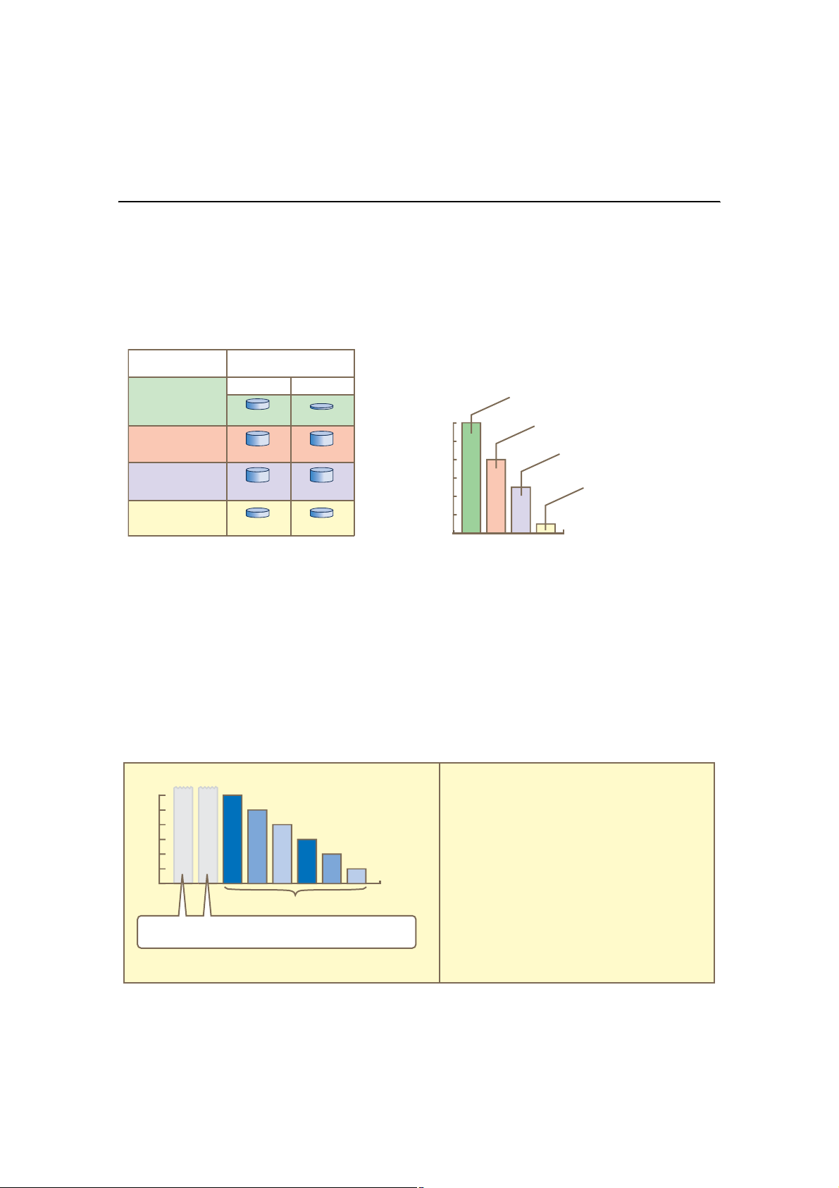
EXAMPLE 3:DEFINING USER PROFILESAND QOS SETTINGS
User profiles contain a grouping of settings that determine the QoS (Quality of Service) for users. In this example,
you define four user profiles and their companion QoS forwarding rates and priorities. The four groups of users are
VoIP phone users, IT staff, corporate employees, and visiting guests. The user profile settings, maximum traffic
forwarding rates, and the WRR (weighted round robin) weights for each user profile is shown in Figure7.
Figure 7 User Profiles and their Forwarding Rates and Weights
Ë-»® Ю±º·´»-
Ò¿³»æ ʱ×Ð
×Üæ î
Ò¿³»æ ×Ì
×Üæ í
Ò¿³»æ Û³°
×Üæ ì
Ò¿³»æ Ù«»-¬-
×Üæ ë
Ú±® ³±-¬ ±º ¬¸» °®±º·´»-ô ¬¸» ³¿¨·³«³ ¬®¿ºº·½ º±®©¿®¼·²¹
®¿¬»- º±® ¿ °®±º·´» ¿®» ¬¸» -¿³» ¿- ¬¸±-» º±® ¿ «-»®ò Þ§
µ»»°·²¹ ¬¸»³ ¬¸» -¿³»ô ¿ -·²¹´» ±²´·²» «-»® ·- ²±¬ ®»-¬®·½¬»¼
¬± ¿ -³¿´´»® ®¿¬» ¬¸¿² ¬¸¿¬ ±º ¬¸» °®±º·´» ¬± ©¸·½¸ ¸» ±® -¸»
¾»´±²¹-ò ø̸» ·²¼·ª·¼«¿´ «-»® ®¿¬» ½¿² ¾» ¬¸» -¿³» ¿- ±®
-³¿´´»® ¬¸¿² ¬¸» °®±º·´» ®¿¬» ¬± ©¸·½¸ ¬¸» «-»® ¾»´±²¹-тч Ъ±®
К±ЧР «-»®-ф ¾»½¿«-» ·²¼·ª·¼«¿´ ½¿´´- «-» ´·¬¬´» ¾¿²¼©·¼¬¸ ши у
км Х¾°-чф ¿ пкрр Х¾°-с°®±º·´» ³¿¨·³«³ ¿´´±©- «° ¬± ол
½±²½«®®»²¬ ª±·½» -»--·±²- °»® Ш·ª»ЯР шол ¨ км г пкррчт
Ó¿¨·³«³ Ì®¿ºº·½
Ú±®©¿®¼·²¹ כּ-
л® Ю±º·´»
ïêðð Õ¾°-êì Õ¾°-
лмррр Х¾°-лмррр Х¾°-
лмррр Х¾°-лмррр Х¾°-
ïððð Õ¾°-ïððð Õ¾°-
л® Ë-»®
Ë-»® Ю±º·´» É»·¹¸¬- øº±® ¬®¿ºº·½ º±®©¿®¼·²¹ «-·²¹ ÉÎÎ÷
øÒ±¬»æ É»·¹¸¬- ¼± ²±¬ ¿°°´§ ¬± -¬®·½¬ ¬®¿ºº·½ º±®©¿®¼·²¹ò÷
É»·¹¸¬-
êð
ëð
ìð
íð
îð
ïð
ð
ðï
̸» ¾¿® ½¸¿®¬ ·²¼·½¿¬»- ¿ ®¿¬·± ±º ¿´´±¬¬»¼ ¾¿²¼©·¼¬¸ ¿³±²¹
¬¸» ¬¸®»» «-»® °®±º·´»- ¾¿-»¼ ±² ¬¸»·® ®»-°»½¬·ª» ©»·¹¸¬-ò
Ü«®·²¹ ¬¸» ½±«®-» ±º ±²» -»½±²¼ô ¿ Ø·ª»ßÐ ¿´´±¬- ïî ¬·³»³±®» ¾¿²¼©·¼¬¸ º±® ʱ×Ð «-»®-ô è ¬·³»- ³±®» º±® ×Ì «-»®-ô
¿²¼ ë ¬·³»- ³±®» º±® Û³° «-»®- ¬¸¿² ·¬ ¿´´±¬- º±® Ù«»-¬-ò
λ³»³¾»® ¬¸¿¬ ¾¿²¼©·¼¬¸ ®¿¬·±²·²¹ ±²´§ ±½½«®- ©¸»² «-¿¹»
·- ¿¬ ³¿¨·³«³ ½¿°¿½·¬§ò
ʱ×Ð øêð÷
×Ì øìð÷
Û³° øîë÷
Ù«»-¬- øë÷
Í»½±²¼-
In addition, there are Aerohive class weights, scheduling types, and rate limits applied to each class of traffic within
a user profile. Through these factors, a HiveAP can further prioritize different types of traffic. The settings used in
this example are shown in Figure8.
Figure 8 Aerohive Class Weights and Rate Limits
é
É»·¹¸¬-
êð
ëð
ìð
íð
îð
ïð
ð
ðï
Ю»½¿«-» ½´¿--»- й ¿²¼ к «-» -¬®·½¬ º±®©¿®¼·²¹ф ©»·¹¸¬- ¿®»
²±¬ ¿°°´·½¿¾´» шТтЯтчт Й»·¹¸¬- ±²´§ ¿°°´§ ¬± ¯«»«»¼ ¬®¿ºº·½т
Ò±¬»æ ײ ¬¸·- »¨¿³°´»ô ¬¸» ½´¿-- ©»·¹¸¬- ¸¿°°»² ¬± ¾» ¬¸» -¿³»
º±® »¿½¸ ±º ¬¸» ¬¸®»» «-»® °®±º·´»-ò ̸»§ ½¿² ¿´-± ¾» ¼·ºº»®»²¬ò
ê
ë
ì
ТтЯтТтЯт
ÉÎÎ øÉ»·¹¸¬»¼ α«²¼ α¾·²÷
ß»®±¸·ª» Ý´¿-- É»·¹¸¬-
øº±® ¿´´ ¬¸®»» «-»® °®±º·´»-÷
í
ß»®±¸·ª» Ý´¿--»-
î
é ó ð
ï
ð
Í»½±²¼-
ß»®±¸·ª» Ý´¿-- כּ Ô·³·¬øº±® ¿´´ ¬¸®»» «-»® °®±º·´»-÷
Ý´¿-- כּ Ô·³·¬ øÕ¾°-÷
øÒ«³¾»® ó Ò¿³»÷ ʱ×Ð ×Ì Û³° Ù«»-¬-
й у Т»¬©±®µ Э±²¬®±´ км лпо лпо км
к у К±·½» км лпо лпо км
л у К·¼»± лк прррр прррр оррр
м у Э±²¬®±´´»¼ Ф±¿¼ лк лмррр лмррр оррр
н у Ы¨½»´´»²¬ Ыºº±®¬ лк лмррр лмррр оррр
о у Ю»-¬ Ыºº±®¬ п лк лмррр лмррр оррр
п у Ю»-¬ Ыºº±®¬ о лк лмррр лмррр оррр
р у Ю¿½µ¹®±«²¼ лк лмррр лмррр оррр
Deployment Guide 45

Chapter 4 HiveManager Examples
VoIP User Profile
1.Click HiveAP Configuration > User Profiles > (Add button).
The New User Profile dialog box appears.
2.On the Generalpage, enter the following:
• User Profile Name: VoIP (You cannot include any spaces when defining a user profile name.)
• User Profile ID: 2
Each user profile must have a unique ID number. When using a local authentication mechanism, this ID links
the user profile to a subinterface (or to the SSID that gets assigned to that subinterface) so that the HiveAP
applies the QoS settings for the user profile to all traffic using that SSID/subinterface. When using a remote
RADIUS authentication scheme for IEEE 802.1X authentication, you must configure the user profile ID as an
attribute on the RADIUS server, as explained in "Configure RADIUS server attributes" on page86.
• Comment: QoS for the VoIP traffic
3.Click the QoS tab, enter the following, and then click OK:
• Entire User Profile Rate Limit: 1600 Kbps
This is the maximum amount of bandwidth that all users belonging to this profile can use. The typical
bandwidth consumption for VoIP is between 8 and 64 Kbps depending on the speech codec used. This setting
supports up to 25 concurrent VoIP sessions using 64-Kbps compression (1600 Kbps / 64 Kbps = 25 sessions).
• Entire User Profile Weight: 60
The weight defines a preference for forwarding traffic. It does not specify a percentage or an amount. Its
value is relative to other weights. However, you can see an automatically calculated percentage of this
weight versus those of other user profiles by clicking View next to Existing User Profile Weight Percentages.
Because you want HiveAPs to favor VoIP traffic over all other types, you give this profile a higher weight.
• Per User Rate Limit: 64 Kbps
This is the maximum amount of bandwidth that a single user belonging to this profile can use. It supports
from 1 to 8 concurrent VoIP sessions, depending on the voice codec used.
• Per User Queue Management: Enter the following items in bold.
Class Number - Name Scheduling Type Weight
7 - Network ControlStrict 0 0% 64
6 - VoiceStrict 0 0% 64
5 - VideoWeighted Round Robin60 28% 56
4 - Controlled LoadWeighted Round Robin50 23% 56
3 - Excellent EffortWeighted Round Robin40 19% 56
2 - Best Effort 1Weighted Round Robin30 14% 56
1 - Best Effort 2Weighted Round Robin20 9% 56
0 - BackgroundWeighted Round Robin10 4% 56
You set the rate limits for Aerohive classes 0 – 5 at 56 Kbps to ensure that—even if the VoIP phone is
updating its software or is otherwise engaged in activity other than voice traffic—some bandwidth remains
reserved for voice.
Note: The default rate limit for Aerohive class 5 (voice) is 512 Kbps, which is large enough to support
conference calls, but for typical one-to-one communications, 64 Kbps is sufficient.
46 Aerohive
Weight %
(Read Only) Rate Limit (Kbps)

IT Staff User Profile
1.Click HiveAP Configuration > QoS Policies > User Profiles > (Add button).
The New User Profile dialog box appears.
2.On the Generalpage, enter the following:
• User Profile Name: IT (You cannot include any spaces when defining a user profile name.)
• User Profile ID: 3
• Comment: QoS for the IT staff
3.Click the QoS tab, enter the following, and then click OK:
• Entire User Profile Rate Limit: 54000 Kbps (default)
This is the maximum amount of bandwidth that all users belonging to this profile can use. This setting
provides IT staff members with the maximum amount of available traffic.
• Entire User Profile Weight: 40
Because you want the HiveAPs to favor IT staff traffic over employee and guest traffic, you give this profile
a higher weight than those, but a lower one than that for voice traffic (see "VoIP User Profile" on page46).
• Per User Rate Limit: 54000 Kbps (default)
This is the maximum amount of bandwidth that a single user belonging to this profile can use. It is the
maximum so that even if only one IT staff member is on the network, he or she can use all the available
bandwidth if needed.
• Per User Queue Management: Keep all the settings at their default values.
Emp (Employees) User Profile
1.Click HiveAP Configuration > QoS Policies > User Profiles > IT > (Clone button).
The Clone User Profile dialog box appears.
2.In the Profile Name field, type Emp, and then click OK.
The Emp User Profile dialog box appears with the same values you entered for the IT profile, except that the
user profile ID has already been changed to 4.
3.In the Generaltab, enter the following:
• User Profile Name: Emp (read only)
• User Profile ID: 4
Because the ID number for the def-user, VoIP, and IT user profiles are 1, 2, and 3 respectively, enter "4"
here. This number can be any unique number from 4 to 15.
• Comment: QoS for employees
4.Click the QoS tab, make the following change while keeping all the other cloned settings, and then click OK:
• Entire User Profile Weight: 25
Because you want the HiveAPs to prioritize IT staff traffic first, employee traffic second, and guest traffic
last, you give this profile a weight of 25. This weight is less than that for IT staff traffic (40) and more than
what you are going to assign to guest traffic (5) next. These weights skew the rate at which the HiveAPs
forward queued traffic using the WRR (weighted round robin) scheduling discipline. Roughly, for every 5
bytes of guest traffic per second, a HiveAP forwards 25 bytes of employee traffic, and 40 bytes of IT traffic.
These numbers are not exact because HiveAPs also have internal weights per class that also affect the
amount of traffic that a HiveAP forwards.
Deployment Guide 47

Chapter 4 HiveManager Examples
Guests User Profile
1.Click HiveAP Configuration > QoS Policies > User Profiles > Emp > (Clone button).
The Clone User Profile dialog box appears.
2.In the Profile Name field, type Guests, and then click OK.
The Guests User Profile dialog box appears with the same values you entered for the IT profile, except that the
user profile ID has already been changed to 5.
3.In the Generaltab, enter the following:
• User Profile Name: Guests (read only)
• User Profile ID: 5
Each user profile must have a unique ID number. Because the ID number for the def-user, VoIP, IT, and Emp
user profiles are 1, 2, 3, and 4 respectively, enter "5" here. This number can be any unique number from 5
to 15.
• Comment: QoS for guests
4.Click the QoS tab, make the following change while keeping all the other cloned settings, and then click OK:
• Entire User Profile Rate Limit: 2000 Kbps
This is a limited amount of bandwidth that all users belonging to this profile can use. This setting provides
guests with a basic amount of available traffic.
• Entire User Profile Weight: 5
Because wireless access for guests is mainly a convenience and not a necessity, you assign it the lowest
weight to give it the lowest priority.
• Per User Rate Limit: 2000 Kbps
This is the maximum amount of bandwidth that a single user belonging to this profile can use. It is the same
as the user profile rate limit so that even if only one guest connects to the network, he or she can use all
the available guest bandwidth if needed.
• Per User Queue Management: Enter the following items in bold. Leave all other cloned settings unchanged.
Class Number - Name Scheduling Type Weight
7 - Network ControlStrict 0 0% 64
6 - VoiceStrict 0 0% 64
5 - VideoWeighted Round Robin60 28% 2000
4 - Controlled LoadWeighted Round Robin50 23% 2000
3 - Excellent EffortWeighted Round Robin40 19% 2000
2 - Best Effort 1Weighted Round Robin30 14% 2000
1 - Best Effort 2Weighted Round Robin20 9% 2000
0 - BackgroundWeighted Round Robin10 4% 2000
48 Aerohive
Weight %
(Read Only) Rate Limit (Kbps)

EXAMPLE 4:SETTING SSID PROFILES
An SSID (service set identifier) is an alphanumeric string that identifies a set of authentication and encryption
services that wireless clients and access points use when communicating with each other. In this example, you
define the following three SSID profiles, which are also shown in Figure9:
SSID Name Security Protocol Other
voipKey method: WPA2-PSK
Encryption method: TKIP
Preshared key (ASCII): CmFwbo1121
Authentication method: Open
corpKey method: WPA2-EAP (802.1X)
Encryption method: CCMP (AES)
Authentication method: EAP (802.1X)
guestKey method: Auto-(WPA or WPA2)-PSK
Encryption method: Auto-TKIP or CCMP (AES)
Preshared key (ASCII): guest123
Authentication method: Open
Note: You can define up to four SSIDs for a single radio in access mode. If hive members use one radio for wireless
backhaul communications, then they must use the other radio in access mode. In this case, a HiveAP can
have a maximum of four SSIDs. If hive members send backhaul traffic completely over wired links, then
both radios can be in access mode and a HiveAP can have a maximum of eight SSIDs.
A MAC filter restricting access only to VoIP
phones specified in the filter.
Employees use the RADIUS server specified
in "Setting AAA RADIUS Settings" on page55
to authenticate themselves using IEEE
802.1X.
The receptionist supplies guests with the
SSID name and configuration details when
they arrive.
Deployment Guide 49

Chapter 4 HiveManager Examples
Figure 9 SSID Profiles Providing Network Access to Different Users
Ë-»® Ю±º·´»-ÍÍ×Ü Ð®±º·´» Ü»º·²·¬·±²-
Ø·ª»ßÐ
ʱ×Ð
ʱ×Ри±²»-
×Ì
Û³°´±§»»-
ݱ®°±®¿¬» Ò»¬©±®µ
Ù«»-¬-
Ê·-·¬·²¹ Ù«»-¬
¿¬ ݱ®°±®¿¬» Í·¬»
ННЧЬж ª±·°
Х»§ У»¬¸±¼ж ЙРЯоуРНХ
Ы²½®§°¬·±² У»¬¸±¼ж МХЧР
Р®»-¸¿®»¼ Х»§ шЯНЭЧЧчж Э³Ъ©¾±ппоп
Я«¬¸»²¬·½¿¬·±² У»¬¸±¼ж С°»²
ННЧЬж ½±®°
Х»§ У»¬¸±¼ж ЙРЯоуЫЯР широтпИч
Ы²½®§°¬·±² У»¬¸±¼ж ЭЭУР шЯЫНч
Я«¬¸»²¬·½¿¬·±² У»¬¸±¼ж ЫЯР широтпИч
ННЧЬж ¹«»-¬
Х»§ У»¬¸±¼ж Я«¬±ушЙРЯ ±® ЙРЯочуРНХ
Ы²½®§°¬·±² У»¬¸±¼ж Я«¬±уМХЧР ±® ЭЭУР шЯЫНч
Р®»-¸¿®»¼ Х»§ шЯНЭЧЧчж ¹«»-¬пон
Я«¬¸»²¬·½¿¬·±² У»¬¸±¼ж С°»²
ОЯЬЧЛН Н»®ª»®- º±®
иротпИ Я«¬¸»²¬·½¿¬·±²
Members of the user profiles "IT" and "Employees" can use SSIDs "voip" and "corp". The SSID with which they associate
is based on how they are attempting to access the network. If they use a VoIP phone, then they associate with the
voip SSID because that is the SSID configured on their phones. If they use a wireless client on a computer, then they
associate with the corp SSID because that is the SSID configured on the wireless client on their computers.
In contrast, members of the user profile “Guests” can only associate with the guest SSID because that is the only
one the receptionist tells them about when they arrive.
voip SSID
1.Click HiveAP Configuration > SSID Profiles > (Add button).
The New SSID Profile dialog box appears.
2.On the Generalpage, enter the following, and leave all other settings with their default values:
• Name: voip (You cannot include any spaces when defining the name of an SSID.)
• Comment: SSID exclusively for VoIP phones
• Key Management: WPA2-PSK
• Encryption Method: TKIP
• Key Type: ASCII Key
• Key Value 1: CmFwbo1121 (The key length can be from 8 to 63 characters.)
3.Click the MAC Filter tab.
4.From the MAC Filter Name drop-down list, choose corpVoIPphones, click Add, and then click OK.
By applying a MAC filter to the voip SSID, you restrict access to VoIP phones matching the specified OUI.
50 Aerohive

corp SSID
1.Click HiveAP Configuration > SSID Profiles > (Add button).
The New SSID Profile dialog box appears.
2.On the Generalpage, enter the following, and then click OK :
• Name: corp
• Comment: SSID for corporate employees
• Key Management: WPA2-EAP (802.1X)
• Encryption Method: CCMP (AES)
• Authentication Method: EAP (802.1X) (This is read-only because the key management choice requires this
authentication method.)
guest SSID
1.Click HiveAP Configuration > SSID Profiles > (Add button).
The New SSID Profile dialog box appears.
2.On the Generalpage, enter the following, and then click OK :
• Name: guest
• Comment: SSID for company guests
• Key Management: Auto-(WPA or WPA2)-PSK
• Encryption Method: Auto-TKIP or CCMP (AES)
• Authentication Method: Open (This is read-only because the key management choice requires this
authentication method.)
• Key Type: ASCII Key
• Key Value 1: guest123
Deployment Guide 51
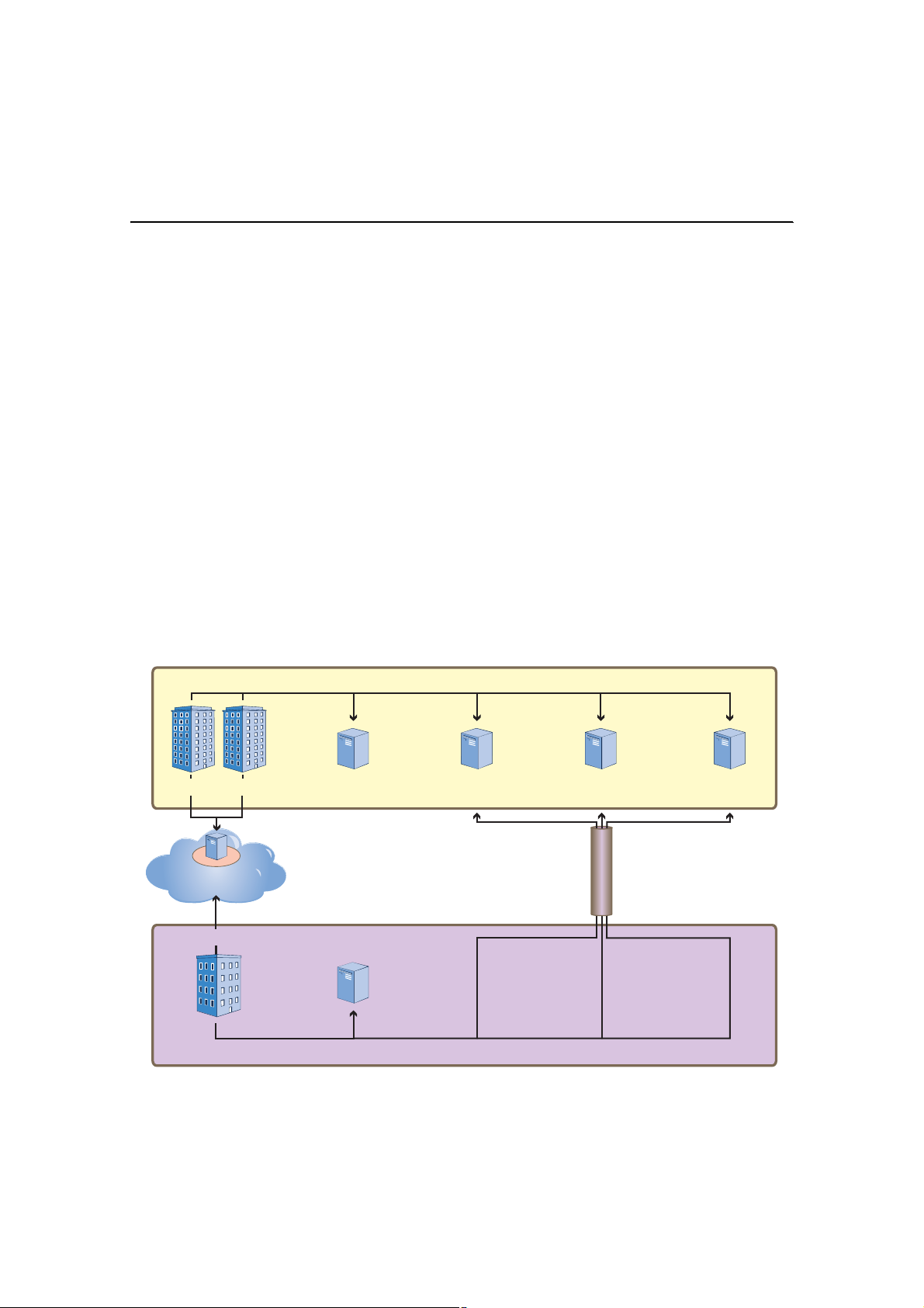
Chapter 4 HiveManager Examples
EXAMPLE 5:SETTING MANAGEMENT SERVICE PARAMETERS
A management service set consists of DNS, syslog, SNMP, and NTP services. HiveAPs use these services for network
communications and logging activities.
In this example, you configure two management service sets, one for each of the device groups that are explained
in "Example 7: Creating Two Device Groups" on page57. Because one device group will be at the corporate HQ site
and the other at the remote branch office, the management services need to be slightly different. Using the clone
capabilities in the HiveManager GUI, you configure the management service set for HQ ("MGT Services - HQ"), clone
it, and modify just the DNS server settings.
For the management services set "hq", you define parameters for the following services:
• Two DNS (Domain Name Service) servers—one primary and one secondary DNS server—both at headquarters.
• One syslog server and one SNMP (Simple Network Management Protocol) server—both at headquarters. The
HiveAPs at the branch office connect to these through a VPN tunnel.
• One NTP (Network Time Protocol) server—located on the public network. HiveAPs synchronize the time on their
system clocks with this server.
For the management services set "branch", you clone "hq" and just change the parameters for the two DNS servers:
• Two DNS servers—The primary DNS server is at the branch site, and the secondary server is at headquarters. The
HiveAPs query the secondary server through a VPN tunnel if queries to the local primary server elicit no replies.
• Syslog and SNMP servers (Same as "hq")
• NTP server (Same as "hq")
Figure 10 Location of Servers in Relation to Each Management Service Set
Ó¿²¿¹»³»²¬ Í»®ª·½»- Í»¬æ •¸¯Œ
ݱ®°±®¿¬» Ø»¿¼¯«¿®¬»®-
λ³±¬» ÒÌÐ Í»®ª»®
орйтпоктзйтлй
Þ®¿²½¸ Ѻº·½»
Ó¿²¿¹»³»²¬ Í»®ª·½»- Í»¬æ •¾®¿²½¸Œ
Ю·³¿®§ ÜÒÍ Í»®ª»®
пртптптол
Ѳ´§ ¬¸» °®·³¿®§ ÜÒÍ -»®ª»® ·¿¬ ¬¸» ¾®¿²½¸ ±ºº·½» -·¬»ò ̸»
ÒÌÐ -»®ª»® ·- ±² ¬¸» °«¾´·½
²»¬©±®µò ß´´ ±¬¸»® ³¿²¿¹»³»²¬
-»®ª»®- ¿®» ¿¬ ¸»¿¼¯«¿®¬»®-ò ß
ÊÐÒ ¬«²²»´ °®±¬»½¬- ¬®¿ºº·½
¾»¬©»»² ¬¸» ¬©± -·¬»-ò
Ю·³¿®§ ÜÒÍ Í»®ª»®
пртототолп
Í»½±²¼¿®§ ÜÒÍ Í»®ª»®
пртптоток
ͧ-´±¹ Í»®ª»®
пртптптон
ÍÒÓÐ Í»®ª»®
пртптптом
ÊÐÒ Ì«²²»´
52 Aerohive

Management Services Set: hq
1.Click HiveAP Configuration > Management Services > (Add button).
The New Management Services dialog box appears.
2.On the General page, enter the following:
• Profile Name: hq (You cannot include spaces in the name of a management services profile.)
• Comment: Mgt settings for hq HiveAPs
DNS Server Configuration:
• Domain Name: apis.com (This is the domain name of the corporation in this example.)
• Click Add, enter the following, and then click OK:
— IP Address: 10.1.1.25
— Comment: HQ Primary DNS Server
• Click Add, enter the following, and then click OK:
— IP Address: 10.1.2.26
— Comment: HQ Secondary DNS Server
Syslog Server Configuration:
• Facility: From the drop-down list, choose a syslog facility with which to tag event log messages from the
HiveAPs. By specifying a particular facility, the syslog server can differentiate all messages from the
same source from messages from other sources.
• Click Add, enter the following, and then click OK:
— Syslog IP Address: (select), 10.1.1.23
— Severity: Choose the minimum severity level for messages that you want to send to the syslog
server. HiveAPs send messages of the level you choose plus messages of all severity levels above it.
For example, if you choose critical, the HiveAP sends the syslog server all messages whose severity
level is critical, alert, or emergency. If you choose emergency, the HiveAPs send only
emergency-level messages.
— Comment: Type a useful text string, such as "Log critical - emergency events".
3.Click the SNMP tab, and then enter the following:
• SNMP Service Enable: (select)
Note: Spaces are not allowed in text strings you enter in the SNMP Contact and SNMP Location fields.
• SNMP Contact: Type contact information for the person to contact if you need to reach a HiveAP admin.
(You cannot include any spaces in the SNMP contact definition.)
SNMP Server Configuration:
• Click Add, enter the following, and then click OK:
— SNMP IP Address: (select), 10.1.1.24 (This is the IP address of the SNMP management system to
which the SNMP agent running on the HiveAPs sends SNMP traps.)
— Community String: Enter a text string that must accompany queries from the management system.
The community string acts similarly to a password. (HiveAPs only accept queries from management
systems that send the correct community string.)
— Version: From the drop-down list, select the version of SNMP that is running on the management
system you intend to use: v1 or v2c.
— Operation: From the drop-down list, choose the type of activity that you want to permit between
the specified SNMP management system and the HiveAPs in the device group to which you (later)
assign this management services profile:
Deployment Guide 53

Chapter 4 HiveManager Examples
get – get commands sent from the management system to a HiveAP to retrieve MIBs
(Management Information Bases), which are data objects indicating the settings or operational
status of various HiveOS components
trap – messages sent from HiveAPs to notify the management system of events of interest
get and trap – permit both get commands and traps
none – cancel all activity, disabling SNMP activity for the specified management system
— Privilege: At the time of this release, "read-only" is the only option available. SNMP admins can read
data that a HiveAP sends them, but they cannot write any data to a HiveAP.
4.Click the Time/Date tab, and then enter the following:
• Time Zone: From the drop-down list, choose the time zone for the HiveAPs to which you intend to apply this
management services profile.
• Enable NTP Client Service: (select)
• Synchronization Interval: Set an interval for polling the NTP (Network Time Protocol) server so that HiveAPs
can synchronize their internal system clock with the server. The default interval is 1440 minutes (once a
day). The possible range is from 60 minutes (once an hour) to 10,080 minutes (once a week).
NTP Server Configuration
• Click Add, enter the following, and then click OK:
— NTP IP Address: (select); 207.126.97.57
— Comment: Enter useful information, such as contact details for the NTP server admin.
Note: You can define only one NTP server per management service set.
• Sync Clock with HiveManager: (clear)
Because you want the HiveAPs to use an NTP server, this option must be cleared. Select this only if you want
the HiveAPs to synchronize their times with that set on the HiveManager.
Management Services Set: branch
1.Click HiveAP Configuration > Management Services > hq > (Clone button).
The Clone Management Services dialog box appears.
2.In the Profile Name field, type branch, and then click OK.
The Management Service - branch dialog box appears with all the settings cloned from "hq".
3.On the General page, modify only the following settings, and then click OK:
• Comment: Mgt settings for branch HiveAPs
DNS Server Configuration:
• Select 10.1.1.25 HQ Primary DNS Server, click Edit, enter the following, and then click OK:
— IP Address: 10.2.2.251
— Comment: Branch Primary DNS Server
54 Aerohive

EXAMPLE 6:SETTING AAA RADIUS SETTINGS
In this example, you define the connection settings for a RADIUS server so that HiveAPs can send RADIUS
authentication requests—encapsulated in EAP (Extensible Authentication Protocol) packets—to the proper
destination.
After corporate employees associate with HiveAPs, they gain network access by authenticating themselves to a
RADIUS server. The authentication process makes use of the IEEE 802.1X standard. Within this context, wireless
clients act as supplicants, HiveAPs as authenticators, and the RADIUS server as the authentication server. The roles
of each participant, packet exchanges, and connection details for the RADIUS server are shown in Figure11.
Figure 11 IEEE 802.1X Authentication Process
Primary RADIUS server
IP address: 10.1.1.15
Shared secret: J7ix2bbbLA
Authentication port: 1812
Accounting port: 1813
Server priority: First
Í«°°´·½¿²¬
øÉ·®»´»-- Ý´·»²¬÷
ß ©·®»´»-- ½´·»²¬ñ-«°°´·½¿²¬ -¬¿®¬- ¿²
¿--±½·¿¬·±² °®±½»-- ©·¬¸ ¿ Ø·ª»ßÐò
̸» -«°°´·½¿²¬ -»²¼- ¿² ß½½»--óλ¯«»-¬ ·² ¿
ÌÔÍó»²½¿°-«´¿¬»¼ °¿½µ»¬ ¬± ¬¸» ¿«¬¸»²¬·½¿¬±®ò
М¸» ¿«¬¸»²¬·½¿¬±® ¼»½¿°-«´¿¬»- ¬¸» ±«¬»®
°¿½µ»¬ ¿²¼ ª·»©- ¬¸» ОЯЬЧЛН ¿¬¬®·¾«¬»-
·²¼·½¿¬·²¹ ©¸»¬¸»® ¬¸» -«°°´·½¿²¬ ·- ¿½½»°¬»¼
±® ®»¶»½¬»¼ ø¿²¼ °±--·¾´§ ¬¸» «-»® ¹®±«° º±®
¬¸» -«°°´·½¿²¬÷ò
ß«¬¸»²¬·½¿¬±®
øØ·ª»ßÐ÷
М¸» ¿«¬¸»²¬·½¿¬±® ¿¼¼- ¿ ²»© ¸»¿¼»®
ш½±²¬¿·²·²¹ ¬¸» ЧР ¿¼¼®»-- ±º ¬¸» ОЯЬЧЛН
-»®ª»®ч ф »²½¿°-«´¿¬»- ¬¸» МФНу»²½¿°-«´¿¬»¼
°¿½µ»¬ «-·²¹ РЫЯРф ЫЯРуММФНф ±® ЫЯРуМФНф
¿²¼ °®±¨·»- ¬¸» ¬©·½»у»²½¿°-«´¿¬»¼ °¿½µ»¬ ¬±
¬¸» ¿«¬¸»²¬·½¿¬·±² -»®ª»®т
̸» ¿«¬¸»²¬·½¿¬·±² -»®ª»® ®»°´·»- ¬± ¬¸»
¿«¬¸»²¬·½¿¬±® ©·¬¸ »·¬¸»® ¿² ß½½»--óß½½»°¬
±® ß½½»--ó붻½¬ ³»--¿¹» ·² ¿²±¬¸»® ¼±«¾´§
»²½¿°-«´¿¬»¼ °¿½µ»¬ò
1.Click HiveAP Configuration > AAA RADIUS > (Add button).
The New RADIUS Profile dialog box appears.
2.Enter the following:
• RADIUS Configuration Name: auth-1 (You cannot use spaces in the RADIUS profile name.)
• Comment: 802.1X for corp employees
• Retry Interval: 6000 (Seconds)
Enter the period of time that a HiveAP waits before retrying a previously unresponsive primary RADIUS
server. If a primary RADIUS server does not respond to three consecutive attempts—where each attempt
consists of ten authentication requests sent every three seconds (30 seconds for a complete request)—and a
backup RADIUS server has been configured, the HiveAP sends further authentication requests to the backup
Secondary RADIUS Server
IP address: 10.1.2.16
Shared secret: J8Dx2c13Mb
Authentication port: 1812
Accounting port: 1813
Priority: Second
ß«¬¸»²¬·½¿¬·±² Í»®ª»®-
шОЯЬЧЛН Н»®ª»®-ч
Deployment Guide 55

Chapter 4 HiveManager Examples
server. The default is 600 seconds (or 10 minutes). The minimum is 60 seconds and there is no maximum.
Generally, you want to make the retry interval fairly large so that supplicants (that is, wireless clients
requesting 802.1X authentication) do not have to wait unnecessarily as a HiveAP repeatedly tries to connect
to a primary server that is down for an extended length of time.
• Accounting Interim Update Interval: 3600 (default)
This is the interval in seconds for updating the RADIUS accounting server with the cumulative length of a
client’s session.
• RADIUS Server:
• Click Add, enter the following, and then click OK:
— IP Address: 10.1.1.15
— Comment: Primary RADIUS Server
— Shared Secret: J7ix2bbbLA
— Repeat Secret: J7ix2bbbLA
— Auth Port: 1812 (default RADIUS authentication port number)
— Acct Port: 1813 (default RADIUS accounting port number)
— Server Priority: First
• Click Add, enter the following, and then click OK:
— IP Address: 10.1.2.16
— Comment: Backup RADIUS Server
— Shared Secret: J8Dx2c13Mb
— Repeat Secret: J8Dx2c13Mb
— Auth Port: 1812
— Acct Port: 1813
— Server Priority: Second
Note: The shared secret is a case-sensitive alphanumeric string that must be entered on each RADIUS server
exactly as shown above.
3.To close the New RADIUS Profile dialog box, click OK.
RADIUS Server Attributes
On the two RADIUS servers (also referred to as "RADIUS home servers"), define the HiveAPs as RADIUS clients.1 Also,
configure the following attributes for the realms to which user accounts matching the two user profiles belong:
Realm for IT (User Profile ID = 2) Realm for Employees (User Profile ID = 3)
Tunnel Type = GRE (value = 10)Tunnel Type = GRE (value = 10)
Tunnel Medium Type = IP (value = 1) Tunnel Medium Type = IP (value = 1)
Tunnel Private Group ID = 2Tunnel Private Group ID = 3
The RADIUS server returns one of the above sets of attributes based on the realm to which an authenticating user
belongs. HiveAPs then use the combination of returned RADIUS attributes to assign users to user profile 2 ("IT") or 3
("Employees"). Note that these attributes do not create a GRE tunnel, which the tunnel type might seem to indicate.
1.If you use RADIUS proxy servers, then direct RADIUS traffic from the HiveAPs to them instead of the RADIUS home servers. This
approach offers the advantage that you only need to define the proxy servers as clients on the RADIUS home servers. You can
then add and remove multiple HiveAPs without having to reconfigure the RADIUS home servers after each change.
56 Aerohive

EXAMPLE 7:CREATING TWO DEVICE GROUPS
Through the HiveManager, you can configure two broad types of features:
• Policy-based features – In combination, these features form policies that control how users access the network:
QoS (Quality of Service) forwarding mechanisms and rates, user profiles, SSID profiles, management services
(DNS, NTP, syslog), AAA (authentication, authorization, accounting) RADIUS settings, and VLAN assignments.
• Connectivity-based features – These features control how hive members communicate with the network and
how radios operate at different modes, frequencies, and signal strengths.
A device group is an assembly of policy-based configurations that the HiveManager pushes to all HiveAPs that you
assign to the group. Because these configurations are policy-based, they can apply across multiple physical devices.
In contrast, connectivity-based configurations are more appropriately applied to smaller sets of devices or at the
individual device level itself.
In this example, you create device group "hq1" for the corporate headquarters and add user group-SSID profile-VLAN
ID mappings, plus the management services set and AAA settings. You then create another device group for the
branch office and name it "branch1". This group will have different management settings.
Figure 12 Components Constituting DeviceGroup-1
HiveAP Configuration > Device Groups >
Defined in "Example 5: Setting Management Service Parameters"
on page52
Defined in "Example 6: Setting AAA RADIUS Settings" on page55
Defined in "Mapping the MAC OUI and Services to Aerohive
Defined in "Example 3: Defining User Profiles and QoS Settings"
on page45
Defined in "Example 4: Setting SSID Profiles" on page49
DeviceGroup-1
1.Click HiveAP Configuration > Device Groups > (Add button).
The New Device Group dialog box appears.
2.Enter the following:
• Group Name: DeviceGroup-1 (You cannot use spaces in the device group name.)
• Description: Enter a useful description, such as "All HiveAPs at HQ".
Deployment Guide 57

Chapter 4 HiveManager Examples
• Configuration Settings:
• Network Management Settings: hq
The management services set was previously created. For details, see "Example 5: Setting Management
Service Parameters" on page52.
• AAA RADIUS Settings: auth-1
The AAA RADIUS settings were previously defined in "Setting AAA RADIUS Settings" on page55.
• QoS Enabled: (select)
QoS Classification and Marking Policy: VoIP-QoS
The QoS classification policy was previously defined. See "Mapping the MAC OUI and Services to
Aerohive Classes" on page43.
3.In the Profile Mappings section, click Add.
The New SSID-User Profile-VLAN Mapping dialog box appears.
4.Enter the following:
• SSID: voip
This SSID was previously defined in "voip SSID" on page50.
• Bind Radio Mode: 11b/g
In this example, you want to use IEEE 802.11b/g for network access traffic because a broader range of
wireless clients support IEEE 802.11b than IEEE 802.11a, which came out two years later (despite its
alphabetical precedence), and it provides slightly greater coverage.
The three choices in the Bind Radio Mode drop-down list are as follows:
— 11a+11b/g: This binds the SSID to two subinterfaces, each linked to a different radio operating in
separate frequency bands. Radio 1 supports IEEE 802.11b/g and operates in the 2.4 GHz band, and
radio 2 supports IEEE 802.11a and operates in the 5 GHz band.
This is a good approach if the HiveAPs need to interoperate with some wireless clients that only
support 802.11b/g and others that only support 802.11a. In this case, both of the wifi
interfaces—wifi0 and wifi1—are in access mode. On the other hand, if hive members need to
support wireless backhaul communications, then you cannot take this approach because one
interface (wifi1 by default) will need to be in backhaul mode and, therefore, cannot support an
SSID.
— 11b/g: This binds the SSID to a subinterface linked to a radio operating at 2.4 GHz for the IEEE
802.11b or IEEE 802.11g standards.
— 11a: This binds the SSID to a subinterface using an antenna operating at 5 GHz for the IEEE 802.11a
standard.
5.Click in the empty User Profile cell to activate the drop-down list, and then choose VoIP.
6.Select Default, set the VLAN ID as 2, and then click OK.
The New SSID-User Profile-VLAN Mapping dialog box closes.
7.In the Profile Mappings section in the New Device Group dialog box, click Add.
The New SSID-User Profile-VLAN Mapping dialog box appears.
8.Enter the following:
• SSID: corp
This SSID was previously defined in "corp SSID" on page51.
• Bind Radio Mode: 11b/g
58 Aerohive

9.Click in the empty User Profile cell to activate the drop-down list, choose Emp, select Default for Employees
user profile, set the VLAN ID as 1, and then click Add.
10.Click in the new empty User Profile cell to activate the drop-down list, choose IT, set the VLAN ID as 1, and
then click OK.
The New SSID-User Profile-VLAN Mapping dialog box closes.
11.In the Profile Mappings section in the New Device Group dialog box, click Add.
The New SSID-User Profile-VLAN Mapping dialog box appears again.
12.Enter the following:
• SSID: guest
This SSID was previously defined in "guest SSID" on page51.
• Bind Radio Mode: 11b/g
13.Click in the empty User Profile cell to activate the drop-down list, choose Guests, select Default, set the VLAN
ID as 3, and then click OK.
The New SSID-User Profile-VLAN Mapping dialog box closes.
14.To close the New Device Group dialog box, click OK.
DeviceGroup-2
1.Click HiveAP Configuration > Device Groups > DeviceGroup-1 > (Clone button).
The Clone Device Group dialog box appears.
2.In the Group Name field, enter DeviceGroup-2, and then click OK.
The DeviceGroup-2 dialog box appears populated with the settings cloned from DeviceGroup-1.
3.Edit the description and network management settings, leave the others as they are, and then click OK:
• Description: Modify the description to something such as "All HiveAPs at the branch site".
• Configuration Settings: Network Management Settings: branch
Deployment Guide 59

Chapter 4 HiveManager Examples
EXAMPLE 8:CREATING THREE HIVE PROFILES
A hive is a set of HiveAPs that exchange information with each other over a layer-2 switched network to form a
collaborative whole. In this example, you define three hive profiles: one for each building. Later, in "Example 9:
Assigning HiveAPs to a Device Group, Radio Profile, Hive Profile, and Topology Map" on page61, you assign HiveAP
devices to these profiles.
Note: A device group is different from a hive. Whereas the members of a device group share a set of policy-based
configurations, the members of a hive communicate with each other and coordinate their activities as
access points. Device group members share configurations. Hive members work collaboratively.
Hive1
1.Click HiveAP Configuration > Hive Profiles > (Add button).
The New Hive Profile dialog box appears.
2.Enter the following, leave the other options at their default settings, and then click OK:
• Name: Hive1 (You cannot use spaces in the name of a hive.)
• Comment: Enter a meaningful comment, such as "Hive for HQ, Bldg 1"
• Native VLAN: 1
Note: Hive communications must use the native VLAN in the switch infrastructure. This is the untagged VLAN
and typically uses ID 1.
• Password: (clear)
The password string is what hive members use when authenticating themselves to each other over the
wireless backhaul link using WPA-PSK CCMP (AES). If you do not enter a password string, the HiveManager
derives a default password from the hive name. The password can be from 8 to 63 characters long and
contain special characters. If the string has any blank spaces, enclose the entire string within double
quotation marks (for example, "password string").
Hive2
1.Click HiveAP Configuration > Hive Profiles > Hive1 > (Clone button).
The Clone Hive Profile dialog box appears.
2.In the Profile Name field, type Hive2, and then click OK.
The Hive2 Hive Profile dialog box appears.
3.Modify the comment to an appropriate description for Hive2, such as "Hive for HQ, Bldg 2", leave the other
options at their default settings, and then click OK.
Hive3
1.Click HiveAP Configuration > Hive Profiles > Hive2 > (Clone button).
The Clone Hive Profile dialog box appears.
2.In the Profile Name field, type Hive3, and then click OK.
The Hive3 Hive Profile dialog box appears.
3.Modify the comment to an appropriate description for Hive3, such as "Hive for Branch Site", leave the other
options at their default settings, and then click OK.
60 Aerohive
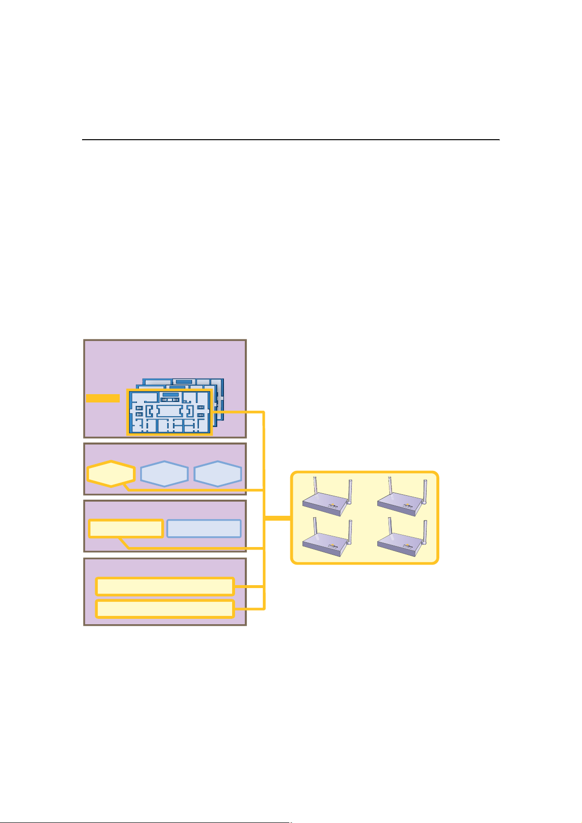
EXAMPLE 9:ASSIGNING HIVEAPSTOA DEVICE GROUP, RADIO
PROFILE, HIVE PROFILE, AND TOPOLOGY MAP
After completing the steps in the previous examples, you can now assign the following device settings as
appropriate to each detected HiveAP:
• Device group (created in "Example 7: Creating Two Device Groups" on page57)
• Radio profile (default radio profiles)
• Hive profile (created in "Example 8: Creating Three Hive Profiles" on page60)
• Map (uploaded in "Example 1: Mapping Locations and Installing HiveAPs" on page37)
As the above list indicates, this example makes use of the two default radio profiles: def-radio-profile-mode(bg) for
its interfaces in access mode, and def-radio-profile-mode(a) for its interfaces in backhaul mode. The assignment of
device settings to HiveAPs is presented conceptually in Figure13.
Figure 13 Assigning Device Settings to HiveAPs
Device Settings
̱°±´±¹§ Ó¿°-
ШПуЮпуЪн
ШПуЮпуЪо
ШПуЮпуЪп
ò ò ò ò òò ò ò
ò ò ò ò òò ò ò
ò ò ò ò òò ò ò
You assign particular combinations of device settings to sets
of discovered HiveAPs.
For example, the four HiveAPs shown below were installed on
the first floor of building 1 at the corporate headquarters. You
know this because—during their installation—you either
configured their SNMP sysLocation MIB object to indicate the
map titled "HQ-B1-F1" or you wrote down the MAC addresses
and locations of all the HiveAPs you installed (see "Example
1: Mapping Locations and Installing HiveAPs" on page37).
Ø·ª» Ю±º·´»-
Ü·-½±ª»®»¼ Ø·ª»ßÐ-
Ø·ª»ï Ø·ª»íØ·ª»î
Ü»ª·½» Ù®±«°-
Ü»ª·½»Ù®±«°óïÜ»ª·½»Ù®±«°óî
ο¼·± Ю±º·´»-
¼»ºó®¿¼·±ó°®±º·´»ó³±¼»ø¾¹÷ Š ß½½»--
¼»ºó®¿¼·±ó°®±º·´»ó³±¼»ø¾¹÷ Š Þ¿½µ¸¿«´
Because you know where the HiveAPs are located, you
assign them to the HQ-B1-F1 map, Hive1, DeviceGroup-1,
and the two default radio profiles: def-radio-profile-mode(bg)
for network access and def-radio-profile-mode(a) for wireless
backhaul communications.
In addition to assigning device settings to the HiveAPs, you also change their login settings. Finally, you update the
HiveAPs with the new configuration settings to complete their deployment.
Deployment Guide 61

Chapter 4 HiveManager Examples
Assigning Device Settings
1.Click HiveAP Management > New HiveAPs > Automatically Discovered.
2.Select a group of HiveAPs associated with the same map to assign their device settings.
If you defined SNMP sysLocation MIB objects as you installed the HiveAPs as explained in "Using SNMP" on
page40, each HiveAP listed in the HiveAP Management > New HiveAPs > Automatically Discovered window will
now include a map title in the Topology Map column. By clicking the Topology Map column header, you can sort
HiveAPs by topology map. You can then select all the HiveAPs belonging to the same map (use shift-click to
select multiple contiguous HiveAPs) and assign them to the same device group, hive profile, and radio profile.
If you tracked HiveAPs by writing their MAC addresses on the maps as explained in "Using MAC Addresses" on
page41, you can sort the HiveAPs in the HiveAP Management > New HiveAPs > Automatically Discovered window
by MAC address. Click the Node ID column header to display the HiveAPs numerically by MAC address. By
referring to the MAC addresses and the title of the map on which you wrote them during the installation, you
can then select all the HiveAPs belonging to the same map (use control-click to select multiple noncontiguous
HiveAPs) and assign them to the same map, device group, hive profile, and radio profile.
3.Click (Modify button).
4.In the HiveAP dialog box, click the General tab, and then enter the following:
• Device Group: Choose the device group that you want to assign to the selected HiveAPs. In this example,
there are two device groups. Assign DeviceGroup-1 to all the HiveAPs at corporate headquarters, and
DeviceGroup-2 to all HiveAPs at the branch office.
• Hive ID-Name: Choose the hive profile that you want to assign to the selected HiveAPs. Assign Hive1 to all
HiveAPs in HQ-B1, Hive2 to all HiveAPs in HQ-B2, and Hive3 to all HiveAPs at Branch1.
• Topology Map: Choose the map that you want to assign to the selected HiveAPs. (If you used the SNMP
sysLocation MIB definition to associate HiveAPs with maps, the HiveManager has already automatically
chosen the correct map.) The maps allow you to organize the HiveAPs by site (HQ or Branch1), then at HQ
by building (HQ-B1 or HQ-B2), and then by floor (HQ-B1-F1, HQ-B1-F2, HQ-B1-F3, and so on).
• Comment: Enter a useful comment for the HiveAPs for future reference such as contact information of the
IT staff member responsible for their maintenance.
5.Click the Advanced tab, enter the following, and then click OK:
• IP Configuration Mode: DHCP (default)
• VLAN for Management Traffic: 1 (default)
• eth0:
— Admin State: Up (default)
— Operation Mode: Backhaul (default)
— Speed: Auto (default)
— Duplex: Auto (Default)
• wifi0:
— Admin State: Down (default)
— Operation Mode: Access (default)
— Radio Profile: def-radio-profile-mode(bg)
— Radio Channel: Auto (Default)
— Radio Power: Auto (Default)
• wifi1
— Admin State: Up (default)
— Operation Mode: Backhaul
— Radio Profile: def-radio-profile-mode(a)
— Radio Channel: Auto (Default)
— Radio Power: Auto (Default)
62 Aerohive

The HiveManager automatically assigns SSIDs voip, corp, and guest to the wifi0.1, wifi0.2, and wifi0.3
subinterfaces respectively.
6.Repeat this procedure with the HiveAPs associated with all the other maps until they are all configured.
7.To accept all the HiveAPs for management through the HiveManager, select all the HiveAPs in the HiveAP
Management > New HiveAPs > Automatically Discovered window, and then click (Accept button).
Changing HiveAP Login Settings
Changing the login settings for the managed HiveAPs is an important security precaution. The default user name and
password are admin and aerohive.
The HiveManager offers great flexibility and convenience in how you assign new login settings. You can assign a new
user name and password to all managed HiveAPs at the same time, or you can assign different user names and
passwords to different subsets of HiveAPs, or you can assign different user names and passwords to individual
HiveAPs one by one.
Note: Admin user names and passwords are case sensitive.
1.Click HiveAP Management > HiveAP Properties.
2.In the HiveAP Properties window, enter the following, and then click OK:
• Total HiveAPs: Select the check boxes of the HiveAP or HiveAPs whose login settings you want to change.
• Change User Name and Password
• User Name: Enter a new admin user name for logging in to the selected HiveAPs. The user name can be
any alphanumeric string from 3 to 20 characters long.
• Password: Enter a new password for the admin to use when logging in to the selected HiveAPs. The
password can be any alphanumeric string from 5 to 8 characters.
• Confirm Password: To confirm the accuracy of the password, enter it again.
The HiveManager sends the new login settings to all the selected HiveAPs. From now on, use the new admin user
name and password when logging in to these HiveAPs.
Note: To preserve its secrecy, the password appears as an encrypted string in the HiveAP CLI.
Updating HiveAP Configurations
At this point, you have assigned device settings to the HiveAPs, accepted them for management, and changed their
login settings. Now, you can push the configurations from the HiveManager to the HiveAPs.
1.Click HiveAP Management > Managed HiveAPs.
2.Select all the HiveAPs in the Managed HiveAPs window, and then click the Upload Configuration button in the
shortcut toolbar.
The Upload Configuration dialog box appears.
3.Select the HiveAPs whose configurations you want to update, select one of the following options for controlling
when the uploaded configurations are activated (by rebooting the HiveAPs), and then click OK:
• Activate at: Select this option and set the time when you want the updated HiveAPs to activate their new
configuration. This is a good choice if you want to stagger the activation, or if you want to load the
configuration now but activate it at a quieter time.
• Activate now: Select this option to load the configuration on the HiveAPs and immediately activate it.
• Until next reboot: Select this option to load the configuration on the HiveAPs but not activate it through
the HiveManager. (It will be activated the next time the HiveAPs reboot.)
Deployment Guide 63

Chapter 4 HiveManager Examples
64 Aerohive

Chapter 5HiveOS
You can deploy a single HiveAP and it will provide wireless access as an autonomous AP (access point). However, if
you deploy two or more HiveAPs in a hive, you can provide superior wireless access with many benefits. A hive is a
set of HiveAPs that exchange information with each other over a layer-2 switched network to form a collaborative
whole (see Figure1). Through coordinated actions based on shared information, hive members can provide the
following services that autonomous APs cannot:
• Consistent QoS (quality of service) policy enforcement across all hive members
• Coordinated and predictive wireless access control that provides fast roaming to clients moving from one hive
member to another
• Best-path routing for optimized data forwarding
• Automatic radio frequency and power selection
Figure 1 HiveAPs in a Hive
Wired or Wireless Hive Communications (Backhaul)
Wireless Network Access Connections
Wired Ethernet Network Connections
Wireless Clients
Hive Members
Wireless Clients
Not shown: Switches for wired backhaul
connections and the portal link to the wired network.
Hive
Wireless Clients
Deployment Guide 65

Chapter 5 HiveOS
COMMON DEFAULT SETTINGSAND COMMANDS
Many major components of HiveOS are automated and typically require no further configuration. For example, radio
power and frequency selection occurs automatically, as does route learning. Also, after defining a hive and its
security protocol suite, all HiveAPs belonging to that hive automatically initiate and maintain communications with
each other.
Additionally, there are many default settings that simplify the setup of a HiveAP because these are the typical
settings for many of the most common deployments. The following are some important default settings and the
commands necessary to change them if you need to do so:
Default Settings Commands
mgt0 interfaceDHCP client = enabledTo disable the DHCP client:
no interface mgt0 dhcp client
To set an IP address:
interface mgt0 ip ip_addr netmask
VLAN ID = 1To set a different VLAN ID:
interface mgt0 vlan number
wifi0 and wifi1
interfaces
Default QoS policydef-user-qos policy:
User profiledefault-profile:
wifi0 mode = access
wifi1 mode = backhaul
wifi0 radio profile = radio_g0
wifi1 radio profile = radio_a0
antenna = internalTo have the wifi0 interface use an external antenna:
channel = automatic selectionTo set a specific radio channel:
power = automatic selectionTo set a specific transmission power level (in dBms):
user profile rate = 54,000 Kbps
user profile weight = 10
user rate limit = 54,000 Kbps
mode = strict forwarding for all
Aerohive classes
classes 0 - 4 rate limit = 54,000 Kbps
class 5 rate limit = 10,000 Kbps
classes 6 - 7 rate limit = 512 Kbps
group ID = 0
policy name = def-user-qos
VLAN ID = 1
To change the mode of the wifi0 or wifi1 interface:
interface { wifi0 | wifi1 } mode { access
| backhaul }
To change the radio profile of the wifi0 or wifi1
interface to a different, previously defined profile:
interface { wifi0 | wifi1 } radio profile
string
interface { wifi0 | wifi1 } radioantenna
external
interface { wifi0 | wifi1 } radiochannel
number
interface { wifi0 | wifi1 } radiopower
number
To change the default QoS policy:
qospolicydef-user-qos qos ah_class
{ strict rate_limit 0 | wrr
rate_limitweight }
qos policy def-user-policy user-profile
rate_limit weight
qos policy def-user-policy user
rate_limit
You cannot change the group ID or QoS policy name
for the default user profile. To change its VLAN ID:
user-profile default-profile vlan-id
number
66 Aerohive

CONFIGURATION OVERVIEW
CONFIGURATION OVERVIEW
The amount of configuration depends on the complexity of your deployment. As you can see in "Deployment
Examples (CLI)" on page69, you can enter a minimum of three commands to deploy a single HiveAP, and just a few
more to deploy a hive.
However, for cases when you need to fine tune access control for more complex environments, HiveOS offers a rich
set of CLI commands. The configuration of HiveAPs falls into two main areas: "Device-Level Configurations" and
"Policy-Level Configurations" on page68. Consider your deployment plans and then refer to the following sections
for guidance on the commands you need to configure them.
Note: To find all commands using a particular character or string of characters, you can do a search using the
following command: show cmds containing string
Device-Level Configurations
Device-level configurations refer to the management of a HiveAP and its connectivity to wireless clients, the wired
network, and other hive members. The following list contains some key areas of device-level configurations and
relevant commands.
• Management
• Administrators, admin privileges, and login parameters
admin { min-password-length | superuser | user } …
• Logging settings
log { buffered | console | debug | facility | flash | host } …
• Connectivity settings
• Interfaces
interface { wifi0 | wifi1 } …
• Subinterfaces
interface { wifi0.number | wifi1.number } …
• Layer 2 and layer 3 forwarding routes
route mac_addr …
ip route { host | net } ip_addr …
• VLAN assignments
For users:
user-profile string group-id number qos-policy string vlan-id number
For hive communications:
hive string native-vlan number
For the mgt0 interface:
interface mgt0 vlan number
• Radio settings
radio profile string …
Deployment Guide 67
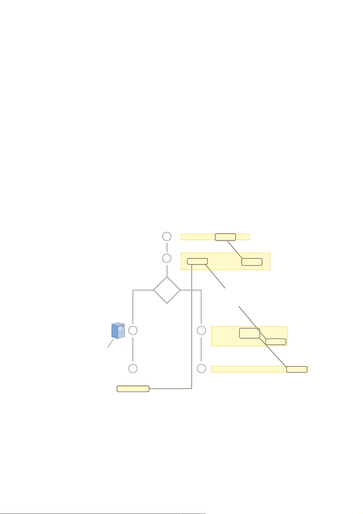
Chapter 5 HiveOS
Policy-Level Configurations
Policies control how wireless clients access the network. The following list contains some key areas of policy-level
configurations and relevant commands.
• QoS settings
qos { classifier-map | classifier-profile | marker-map | marker-profile |
policy } …
• User profiles
user-profile string …
• SSIDs
ssid string …
• AAA (authentication, authorization, and accounting) settings for IEEE 802.1X authentication
aaa radius-server …
While the configuration of most HiveOS features involves one or more related commands, to define and apply a QoS
policy to a group of users, you must configure several different but related features: a QoS policy, a user profile,
and—if you do not authenticate users with a RADIUS server—an SSID that references the user profile, and a
subinterface to which you assign the SSID. The configuration steps are shown in Figure2.
Figure 2 Steps for Configuring and Applying QoS
Ú·®-¬ô ½±²º·¹«®» ¿ Ï±Í °±´·½§ ¬¸¿¬ §±« ©¿²¬ ¬± ¿°°´§
¬± ©·®»´»-- ¬®¿ºº·½ º®±³ ¿ ¹®±«° ±º «-»®-ò
Í»½±²¼ô ½±²º·¹«®» ¿ «-»® °®±º·´» ¬¸¿¬ ®»º»®»²½»- ¬¸»
Ï±Í °±´·½§ §±« ¶«-¬ ½±²º·¹«®»¼ò
М¸» ²»¨¬ -¬»° ¼»°»²¼- ±² ©¸»¬¸»® §±« «-»
¿ ОЯЬЧЛН -»®ª»® ¬± ¿«¬¸»²¬·½¿¬» «-»®-т
Чº §±« «-» ¿ ОЯЬЧЛН -»®ª»®ф ½±²º·¹«®»
·¬ ¬± ®»¬«®² ¿¬¬®·¾«¬»- º±® ¬¸» ®»¿´³ ¬±
©¸·½¸ ¬¸» ©·®»´»-- «-»®- ¾»´±²¹ò ߺ¬»®
¿«¬¸»²¬·½¿¬·²¹ ¿ «-»®ô ¬¸» -»®ª»®
®»¬«®²- ¬¸»-» ¿¬¬®·¾«¬»- ©·¬¸ ¬¸»
ß½½»--óß½½»°¬ ³»--¿¹»ò ̸»
¿¬¬®·¾«¬»- ·²¼·½¿¬» ©¸·½¸
«-»® °®±º·´» ¬± ¿°°´§ ¬± ¬¸»
«-»®ô ¿²¼ ¬¸» °®±º·´» ·² ¬«®²
·²¼·½¿¬»- ¬¸» Ï±Í °±´·½§ ¬±
¿°°´§ò
Л-»® ¿½½±«²¬- ¿®» -¬±®»¼
±² ¬¸» ОЯЬЧЛН Н»®ª»®т
묫®²»¼ ߬¬®·¾«¬»-
Ÿ Ì«²²»´ ̧°» ã ÙÎÛ øª¿´«» ã ïï÷
Ÿ Ì«²²»´ Ó»¼·«³ ̧°» ã ×Ð øª¿´«» ã ï÷
Ÿ Ì«²²»´ Ю·ª¿¬» Ù®±«° ×Ü ã «-»®Á°®±º·´»Á·¼
̸» ¿¬¬®·¾«¬»- ·²¼·½¿¬» ©¸·½¸ «-»® °®±º·´» ¬± ¿°°´§ ¬± ¬¸» «-»®ô
¿²¼ ¬¸» °®±º·´» ·² ¬«®² ·²¼·½¿¬»- ©¸·½¸ Ï±Í °±´·½§ ¬± ¿°°´§ò
í
ï
î
ОЯЬЧЛН
Í»®ª»®á
¯±- °±´·½§ -¬®·²¹ òòò
«-»®ó°®±º·´» -¬®·²¹ ¹®±«°ó·¼
²«³¾»® ¯±-ó°±´·½§ -¬®·²¹
ª´¿²ó·¼ ²«³¾»®
ұǻ-
Чº §±« ¼± ²±¬ «-» ¿ ОЯЬЧЛН -»®ª»®ф
½®»¿¬» ¿² ННЧЬ ¬¸¿¬ -°»½·º·»- ¬¸» «-»®
°®±º·´» ЧЬ ¿- ·¬- ¼»º¿«´¬ «-»® °®±º·´»т
-»¬ --·¼ -¬®·²¹
í
-»¬ --·¼ -¬®·²¹ ¼»º¿«´¬ó
«-»®ó°®±º·´»ó·¼ ²«³¾»®
ß--·¹² ¬¸» ÍÍ×Ü ¬± ¿ -«¾·²¬»®º¿½»ò
ìì
·²¬»®º¿½» ·²¬»®º¿½» --·¼ -¬®·²¹
М¸» Ш·ª»ЯР ¿°°´·»- ¬¸» П±Н °±´·½§ ¬± ¿´´
©·®»´»-- ½´·»²¬- ¬¸¿¬ ¿--±½·¿¬» ©·¬¸ ¬¸» ННЧЬт
68 Aerohive

Chapter 6Deployment Examples (CLI)
This chapter presents several deployment examples to introduce the primary tasks involved in configuring HiveAPs
through the HiveOS CLI.
In "Deploying a Single HiveAP" on page70, you deploy one HiveAP as an autonomous access point. This is the
simplest configuration: you only need to enter and save three commands.
In "Deploying a Hive" on page73, you add two more HiveAPs to the one deployed in the first example to form a hive
with three members. The user authentication method in this and the previous example is very simple: a preshared
key is defined and stored locally on each HiveAP and on each wireless client.
In "Using IEEE 802.1X Authentication" on page78, you change the user authentication method. Taking advantage of
existing Microsoft AD (Active Directory) user accounts, the HiveAPs use IEEE 802.1X EAP (Extensible Authentication
Protocol) to forward authentication requests toa RADIUS server whose database is linked to that of the AD server.
In "Applying QoS" on page81, you apply QoS (Quality of Service) filters to user traffic so that delay-sensitive voice
traffic receives higher priority than other more delay-resistant traffic.
Note: To focus attention on the key concepts of an SSID (first example), hive (second example), and IEEE 802.1X
authentication (third example), QoS was intentionally omitted from these examples. However, the QoS
settings you define in the last example can apply equally well to the configurations in the others.
Because each example builds on the previous one, it is recommended to read them sequentially. Doing so will help
build an understanding of the fundamentals involved in configuring HiveAPs.
If you want to view just the CLI commands used in the examples, see "CLI Commands for Examples" on page87.
Having the commands in blocks by themselves makes it easy to copy-and-paste them at the command prompt.
The following are the equipment and network requirements for these examples:
• Equipment
• Management system (computer) capable of creating a serial connection to the HiveAP
• VT100 emulator on the management system
• Serial cable (also called a "null modem cable") that ships as an option with the HiveAP product. You use this
to connect your management system to the HiveAP.
Note: You can also access the CLI by using Telnet or SSH (Secure Shell). After connecting a HiveAP to the
network, make either a Telnet or SSH connection to the IP address that the DHCP server assigns the
mgt0 interface.
• Network
• Layer 2 switch through which you connect the HiveAP to the wired network
• Ethernet cable—either straight-through or cross-over
• Network access to a DHCP server
• For the third and fourth examples, network access to an AD (Active Directory) server and RADIUS server
Deployment Guide 69

Chapter 6 Deployment Examples (CLI)
EXAMPLE 1:DEPLOYINGA SINGLE HIVEAP
In this example, you deploy one HiveAP (HiveAP-1) to provide network access to a small office with 15 – 20 wireless
clients. You only need to define the following SSID (service set identifier) parameters on the HiveAP and clients:
• SSID name: employee
• Security protocol suite: WPA-auto-psk
• WPA – Uses Wi-Fi Protected Access, which provides dynamic key encryption and mutual authentication of
the client and HiveAP
• Auto – Automatically negotiates WPA or WPA2 and the encryption protocol: AES (Advanced Encryption
Standard) or TKIP (Temporal Key Integrity Protocol)
• PSK – Derives encryption keys from a preshared key that the client and HiveAP both already have
• Preshared key: N38bu7Adr0n3
After defining SSID "employee" on HiveAP-1, you then bind it to the wifi0.1 subinterface, which is in access mode by
default. The wifi0.1 subinterface operates at the same frequency as the wifi0 interface, which by default is 2.4 GHz
(in accordance with the IEEE 802.11b and 802.11g standards). This example assumes that the clients also support
either 802.11b or IEEE 802.11g.
Note: By default, the wifi1 interface is in backhaul mode and operates at 5 GHz to support IEEE 802.11a. To
put wifi1 in access mode so that both interfaces provide access—the wifi0.1 subinterface at 2.4 GHz
and the wifi1.1 subinterface at 5 GHz—enter this command: interface wifi1 mode access.
Then, in addition to binding SSID "employee" to wifi0.1 (as explained in step2), also bind it to wifi1.1.
Figure 1 Single HiveAP for a Small Wireless Network
Wireless Network-1
Wireless clients associate
with HiveAP-1 using SSID
"employee" with the security
suite WPA-auto-psk
(PSK = N38bu7Adr0n3).
HiveAP-1SwitchFirewall
wifi0.1 subinterface
SSID "employee"
Access mode
IEEE 802.11b/g
Physical interface: eth0
Logical interface: mgt0
Backhaul mode
Network portal
Wired Network
Internet
The wireless clients and the mgt0
interface on HiveAP-1 receive their
IP addresses and associated TCP/IP
settings from the DHCP server.
DHCP Server
Step 1Log in through the console port
1.Connect the power cable from the DC power connector on the HiveAP to the AC/DC power adaptor that ships
with the device as an option, and connect that to a 100 – 240-volt power source.
Note: If the switch supports PoE (Power over Ethernet), the HiveAP can receive its power that way instead.
The Power LED glows steady amber during the bootup process. After the bootup process completes, it then
glows steady green to indicate that the firmware is loaded and running.
70 Aerohive

2.Connect one end of an RS-232 serial (or "null modem") cable to the serial port (or Com port) on your
management system.
3.Connect the other end of the cable to the male DB-9 console port on the HiveAP.
4.On your management system, run a VT100 terminal emulation program, such as Tera Term Pro© (a free terminal
emulator) or Hilgraeve Hyperterminal® (provided with Windows® operating systems). Use the following settings:
• Bits per second (baud rate): 9600
• Data bits: 8
• Parity: none
• Stop bits: 1
• Flow control: none
The Initial CLI Configuration Wizard appears.
5.Because you do not need to configure all the settings presented in the wizard, press CTRL+c to exit it.
The login prompt appears.
6.Log in using the default user name admin and password aerohive.
Step 2Configure the HiveAP
1.Create an SSID and assign it to a subinterface.
ssid employee
ssid employee security protocol-suite wpa-auto-psk ascii-key N38bu7Adr0n3
You first create an SSID named "employee" and then define its protocol suite and preshared key
(N38bu7Adr0n3) in standard ASCII (American Standard Code for Information Interchange) text.
interface wifi0.1 ssid employee
You assign the SSID to the subinterface wifi0.1, which is in access mode by default. A subinterface can
either be in access or backhaul mode. A HiveAP uses subinterfaces in access mode to communicate with
wireless clients accessing the network. A HiveAP uses subinterfaces in backhaul mode to communicate
wirelessly with other HiveAPs when in a hive (see subsequent examples).
2.(Optional) Change the name and password of the superuser.
admin superuser mwebster password 3fF8ha
As a safety precaution, you change the default superuser name and password to mwebster and 3fF8ha.
The next time you log in, use these instead of the default definitions.
Note: By default, the minimum password length is 5 characters. You can change the minimum length by
entering the following command: admin min-password-length <number> (The minimum
password length can be between 5 and 8 characters.)
save config
You save your changes to the currently running configuration. The HiveAP configuration is complete.
exit
You log out of the serial session.
Deployment Guide 71

Chapter 6 Deployment Examples (CLI)
Step 3Configure the wireless clients
Define the "employee" SSID on all the wireless clients. Specify WPA-PSK for network authentication, AES or TKIP
for data encryption, and the preshared key N38bu7Adr0n3.
Step 4Position and power on the HiveAP
1.Place the HiveAP within range of the wireless clients and, optionally, mount it as explained in "Mounting the
HiveAP" on page15.
2.Connect an Ethernet cable from the PoE port to the network switch.
3.If you have powered off the HiveAP, power it back on by reconnecting it to a power source.
When you power on the HiveAP, the mgt0 interface, which connects to the wired network through the eth0 port
(labeled "POE" for "Power over Ethernet" on the chassis), automatically receives its IP address through DHCP
(Dynamic Host Configuration Protocol).
Step 5Check that clients can form associations and access the network
1.To check that a client can associate with the HiveAP and access the network, open a wireless client application
and connect to the "employee" SSID. Then contact a network resource, such as a web server.
2.Log in to the HiveAP CLI, and check that you can see the MAC address of the associated client and an indication
that the correct SSID is in use by entering the following command:
-¸±© --·¼ »³°´±§»» -¬¿¬·±²-
ݸ¿² ó ½¸¿²²»´ ²«³¾»®ô ÎÍÍ× ó λ½»·ª» Í·¹²¿´ ͬ®»²¹¬¸ ×¼»²¬·º·»®
ßóÓ±¼» ó ß«¬¸»²¬·½¿¬·±² ³±¼»ô Ý·°¸»® ó Û²½®§°¬·±² ³±¼»
ßóÌ·³» ó ß--±½·¿¬»¼ ¬·³»ô ß«¬¸ ó ß«¬¸»²¬·½¿¬»¼
Ó¿½ ß¼¼® ݸ¿² כּ ÎÍÍ× ßóÓ±¼» Ý·°¸»® ßóÌ·³» ÊÔßÒ ß«¬¸
уууууууууууууу уууу уууу уууу уууууу уууууу уууууууу уууу уууу
ррпкж½ºи½жлй¾½ п пУ ки °-µ ¿»-½½³ рржпожмм п З»-
ݸ»½µ ¬¸¿¬ ¬¸» ÓßÝ ¿¼¼®»--
·² ¬¸» ¬¿¾´» ³¿¬½¸»- ¬¸¿¬ ±º
¬¸» ©·®»´»-- ½´·»²¬ ò
Note: You can also enter the following commands to check the association status of a wireless client:
show auth, show roaming cache, and show roaming cache mac <mac_addr>.
The setup of a single HiveAP is complete. Wireless clients can now associate with the HiveAP using SSID "employee"
and access the network.
ݸ»½µ ¬¸¿¬ ¬¸» ¿«¬¸»²¬·½¿¬·±² ¿²¼
»²½®§°¬·±² ³±¼»- ³¿¬½¸ ¬¸±-» ·²
¬¸» ÍÍ×Ü -»½«®·¬§ °®±¬±½±´ -«·¬»ò
72 Aerohive
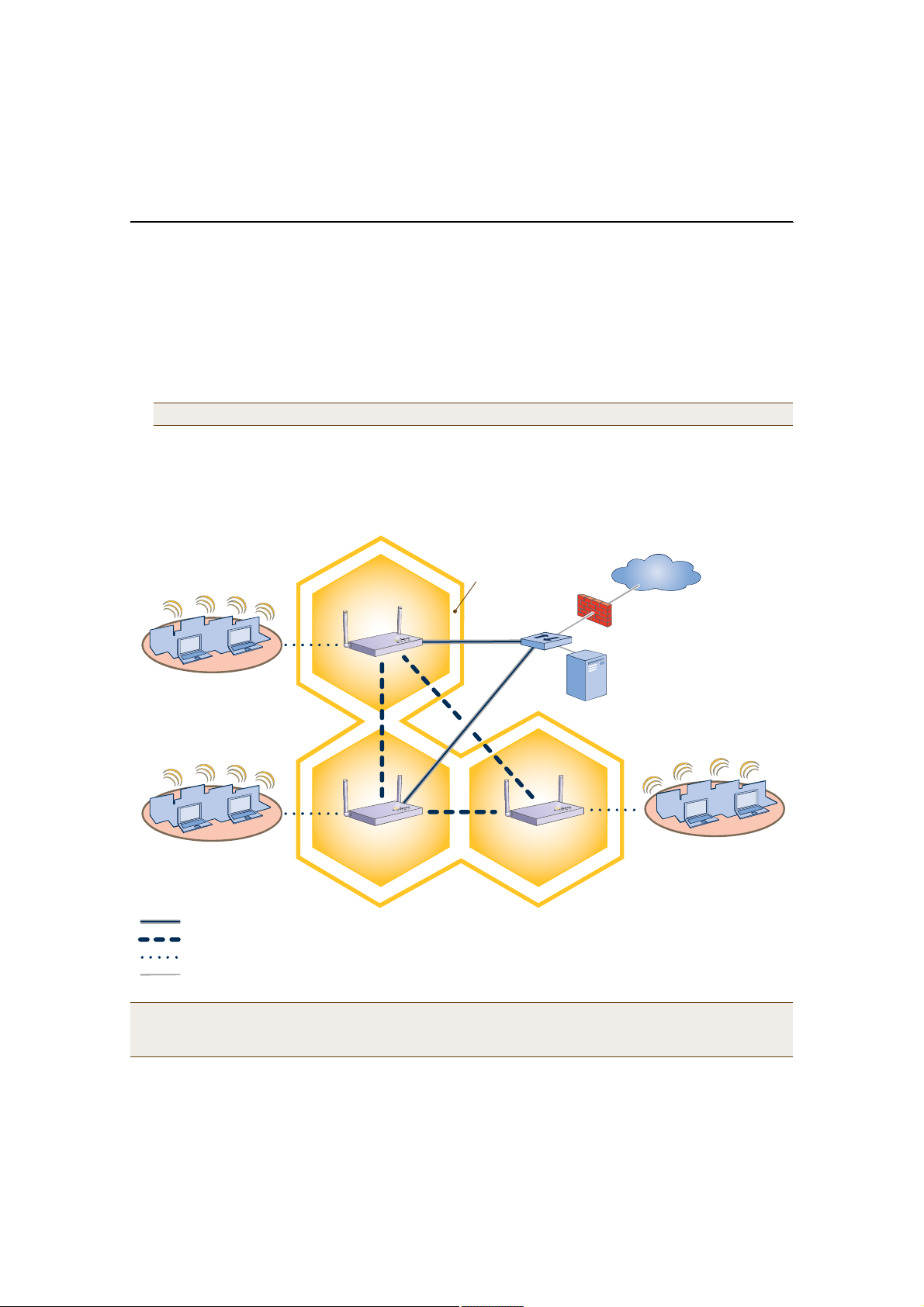
EXAMPLE 2:DEPLOYINGA HIVE
Building on "Deploying a Single HiveAP" on page70, the office network has expanded and requires more HiveAPs to
provide greater coverage. In addition to the basic configuration covered in the previous example, you configure all
three HiveAPs to form a hive within the same layer 2 switched network. The following are the configuration details
for the hive:
• Hive name: hive1
• Preshared key for hive1 communications: s1r70ckH07m3s
Note: The security protocol suite for hive communications is WPA-AES-psk.
HiveAP-1 and -2 are cabled to a switch and use the native ("untagged") VLAN for wired backhaul communications.
They communicate with each other over both wired and wireless backhaul links, the wired link taking precedence.
However, HiveAP-3 only communicates with HiveAP-1 and -2 over a wireless link (see Figure2).
Figure 2 Three HiveAPs in a Hive
Wireless Network-1
HiveAP-1
Wireless Network-2 Wireless Network-3
HiveAP-2HiveAP-3
Wired Hive Backhaul Communications
Wireless Hive Backhaul Communications
Wireless Network Access Connections
Wired Ethernet Network Connections
Hive1
Switch
HiveAP1 and HiveAP2 use both wired and wireless
backhaul methods to communicate with each other.
HiveAP-3 uses only a wireless connection for backhaul
communications with the other two hive members.
Internet
Firewall
DHCP
Server
Note: If all hive members can communicate over wired backhaul links, you can then use both radios for access.
The wifi0 interface is already in access mode by default. To put wifi1 in access mode, enter this command:
interface wifi1 mode access. In this example, however, a wireless backhaul link is required.
Deployment Guide 73

Chapter 6 Deployment Examples (CLI)
Step 1Configure HiveAP-1
1.Using the connection settings described in the first example, log in to HiveAP-1.
2.Configure HiveAP-1 as a member of "hive1" and set the security protocol suite.
hive hive1
You create a hive, which is a set of HiveAPs that collectively distribute data and coordinate activities
among themselves, such as client association data for fast roaming, route data for making optimal
data-path forwarding decisions, and policy enforcement for QoS (Quality of Service) and security.
hive hive1 password s1r70ckH07m3s
You define the password that hive members use to derive the preshared key for securing backhaul
communications with each other. The password must be the same on all hive members.
interface mgt0 hive hive1
By setting "hive1" on the mgt0 interface, you join HiveAP-1 to the hive.
save config
3.Before closing the console session, check the radio channel that HiveAP-1 uses on its backhaul subinterface,
which by default is wifi1.1:
-¸±© ·²¬»®º¿½»
ͬ¿¬» ó Ñ°»®¿¬·±²¿´ -¬¿¬»ô ݸ¿² ó ݸ¿²²»´
ο¼·± ó ο¼·± °®±º·´»ô Ë ó «°ô Ü ó ¼±©²
Ò¿³» Ó±¼» ͬ¿¬» ݸ¿² ÊÔßÒ Î¿¼·± Ø·ª» ÍÍ×Ü
ууууууууууууу уууууууу уууууу ууууу ууууу ууууууууу ууууууууу ууууууууу
Ó¹¬ð ó Ë ó ï ó ¸·ª»ï ó
Û¬¸ð ¾¿½µ¸¿«´ Ë ó ï ó ¸·ª»ï ó
É·º·ð ¿½½»-- Ë ï ó ®¿¼·±Á¹ð ó ó
É·º·ðòï ¿½½»-- Ë ï ó ®¿¼·±Á¹ð ¸·ª»ï »³°´±§»»
É·º·ï ¾¿½µ¸¿«´ Ë ïìç ó ®¿¼·±Á¿ð ó ó
É·º·ïòï ¾¿½µ¸¿«´ Ë ïìç ï ®¿¼·±Á¿ð ¸·ª»ï ó
̸» ©·º·ïòï -«¾·²¬»®º¿½» ·- ·² ¾¿½µ¸¿«´
³±¼» ¿²¼ ·- «-·²¹ ½¸¿²²»´ ïìçò
Write down the channel number for future reference (in this example, it is 149). When configuring
HiveAP-2 and -3, set their wifi1.1 subinterfaces for backhaul communications to this channel.
exit
74 Aerohive

Step 2Configure HiveAP-2 and HiveAP-3
1.Power on HiveAP-2 and log in through its console port.
2.Configure HiveAP-2 with the same commands that you used for HiveAP-1:
ssid employee
ssid employee security protocol-suite wpa-auto-psk ascii-key N38bu7Adr0n3
interface wifi0.1 ssid employee
hive hive1
hive hive1 password s1r70ckH07m3s
interface mgt0 hive hive1
3.(Optional) Change the name and password of the superuser.
admin superuser mwebster password 3fF8ha
4.Check that the channel ID for wifi1 and wifi1.1 is now 149.
show interface
If the channel ID for wifi1 and wifi1.1 is not 149, set it to 149 so that HiveAP-2 uses the same channel as
HiveAP-1 for backhaul communications.
interface wifi1 radio channel 149
Setting the channel for the parent interface (wifi1) sets it for all its subinterfaces. By default, there is
one subinterface for wifi1: wifi1.1. You can configure up to eight subinterfaces for each interface.
save config
exit
5.Repeat the above steps for HiveAP-3.
Step 3Connect HiveAP-2 and HiveAP-3 to the network
1.Place HiveAP-2 within range of its clients and within range of HiveAP-1. This allows HiveAP-1 and -2 to send
backhaul communications to each other wirelessly as a backup path in case either member loses its wired
connection to the network.
2.Connect an Ethernet cable from the PoE port on HiveAP-2 to the network switch.
3.Power on HiveAP-2 by connecting it to a power source.
After HiveAP-2 finishes booting up (indicated when the Power LED changes from steady amber to steady green),
it discovers another member of hive1 (HiveAP-1). The two members use the security protocol suite to
authenticate each other and establish a security association for encrypting backhaul communications between
themselves.
4.Place HiveAP-3 within range of its wireless clients and one or both of the other hive members.
5.Power on HiveAP-3 by connecting it to a power source.
After HiveAP-3 boots up, it discovers the two other members of hive1 over a wireless backhaul link. The
members use the security protocol suite to authenticate themselves and establish a security association for
encrypting backhaul communications among themselves. HiveAP-3 then learns its default route to the wired
network from the other hive members. If the other members send routes with equal costs—which is what
happens in this example—HiveAP-3 uses the first route it receives. When it learns this route, it can
communicate with the DHCP server to get an IP address for its mgt0 interface.
Deployment Guide 75
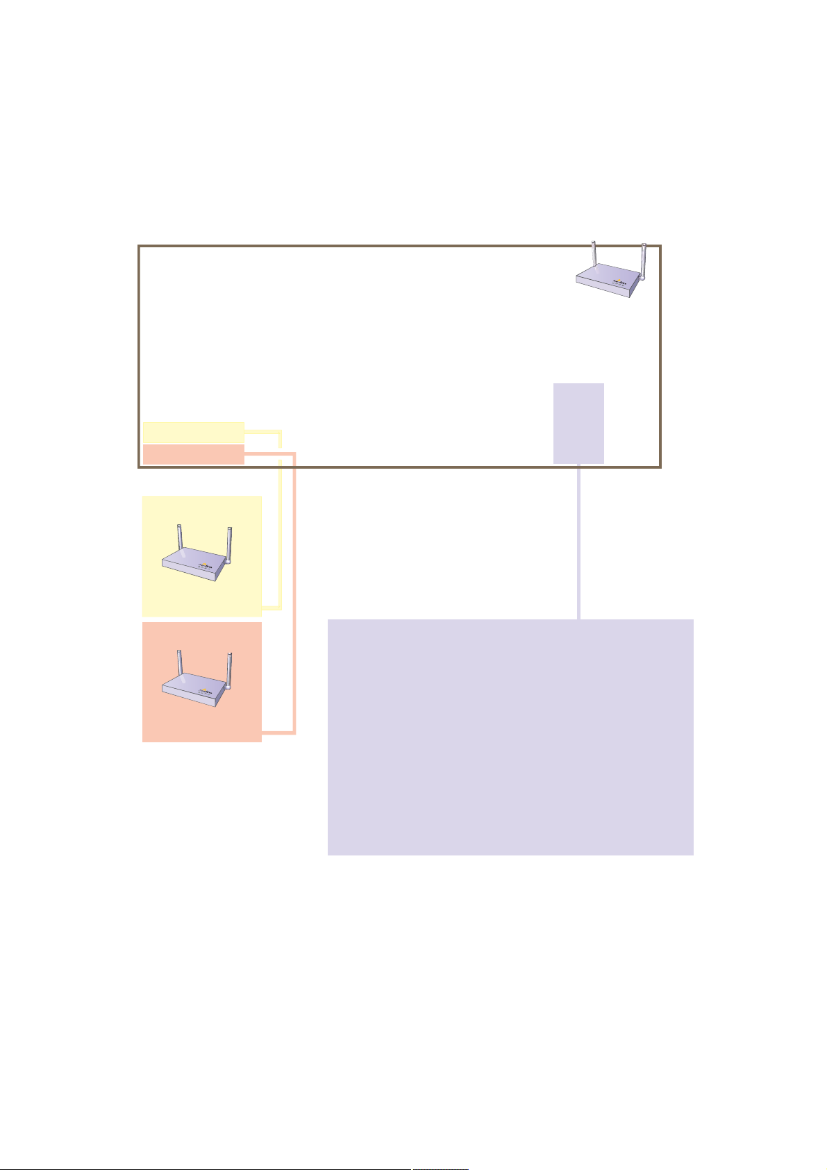
Chapter 6 Deployment Examples (CLI)
6.Check that HiveAP-3 has associated with the other members at the wireless level.
Ô±¹ ·² ¬± Ø·ª»ßÐóí ¿²¼ »²¬»® ¬¸·- ½±³³¿²¼ ¬± -»» ·¬- ²»·¹¸¾±®- ·² ¸·ª»ïæ
-¸±© ¸·ª» ¸·ª»ï ²»·¹¸¾±®-
²»·¹¸¾±® -¬¿¬·±²- ±º ·²¬»®º¿½» ©·º·ïòïæ
ݸ¿² ó ½¸¿²²»´ ²«³¾»®ô ÎÍÍ× ó λ½»·ª» Í·¹²¿´ ͬ®»²¹¬¸ ×¼»²¬·º·»®
ßóÓ±¼» ó ß«¬¸»²¬·½¿¬·±² ³±¼»ô Ý·°¸»® ó Û²½®§°¬·±² ³±¼»
ݱ²²óÌ·³» ó ݱ²²»½¬»¼ ¬·³»ô Ø-¬¿¬» ó Ø·ª» ͬ¿¬»
Ó¿½ ß¼¼® ݸ¿² כּ ÎÍÍ× ßóÓ±¼» Ý·°¸»® ݱ²²óÌ·³» Ø-¬¿¬» Ø·ª»
уууууууууууууу уууу уууу уууу уууууу уууууу ууууууууу уууууу ууууу
ррпзжййрржррои пмз лмУ кр °-µ ¿»-½½³ рржпмжпл Я«¬¸ ¸·ª»п
ррпзжййрржррйи пмз лмУ лн °-µ ¿»-½½³ рржпмжпк Я«¬¸ ¸·ª»п
Ò»·¹¸¾±®-
Ø·ª»ßÐóï
©·º·ïòï ÓßÝ ß¼¼®»--
ррпзжййрржррои
ײ ¬¸» ±«¬°«¬ ±º ¬¸» -¸±© ¸·ª» ¸·ª»ï
²»·¹¸¾±®- ½±³³¿²¼ô §±« ½¿² -»»
¸·ª»ó´»ª»´ ¿²¼ ³»³¾»®ó´»ª»´ ·²º±®³¿¬·±²ò
ɸ»² §±« -»» ¬¸» ÓßÝ ¿¼¼®»-- ±º ¬¸»
±¬¸»® ¸·ª» ³»³¾»®-ô §±« µ²±© ¬¸¿¬
Ø·ª»ßÐóí ´»¿®²»¼ ¬¸»³ ±ª»® ¿ ©·®»´»-¾¿½µ¸¿«´ ´·²µò
Ø·ª»ßÐóí
Ø·ª»ßÐóî
©·º·ïòï ÓßÝ ß¼¼®»--
ррпзжййрржррйи
76 Aerohive
̸» º±´´±©·²¹ ¿®» ¬¸» ª¿®·±«- ¸·ª» -¬¿¬»- ¬¸¿¬ ½¿² ¿°°»¿®æ
Ü·-ª øÜ·-½±ª»®÷ ó ß²±¬¸»® Ø·ª»ßÐ ¸¿- ¾»»² ¼·-½±ª»®»¼ô ¾«¬ ¬¸»®» ·- ¿
³·-³¿¬½¸ ©·¬¸ ·¬- ¸·ª» ×Üò
Ò»·¾±® øÒ»·¹¸¾±®÷ ó ß²±¬¸»® Ø·ª»ßÐ ¸¿- ¾»»² ¼·-½±ª»®»¼ ©¸±-» ¸·ª»
×Ü ³¿¬½¸»-ô ¾«¬ ·¬ ¸¿- ²±¬ §»¬ ¾»»² ¿«¬¸»²¬·½¿¬»¼ò
Ý¿²¼Ð® øÝ¿²¼·¼¿¬» л»®÷ ó ̸» ¸·ª» ×Ü ±² ¿ ¼·-½±ª»®»¼ Ø·ª»ßÐ
³¿¬½¸»-ô ¿²¼ ·¬ ½¿² ¿½½»°¬ ³±®» ²»·¹¸¾±®-ò
ß--±½Ð¼ øß--±½·¿¬·±² л²¼·²¹÷ ó ß Ø·ª»ßÐ ·- ±² ¬¸» -¿³» ¾¿½µ¸¿«´
½¸¿²²»´ô ¿²¼ ¿² ¿--±½¿¬·±² °®±½»-- ·² °®±¹®»--ò
ß--±½¼ øß--±½·¿¬»¼÷ ó ß Ø·ª»ßÐ ¸¿- ¿--±½·¿¬»¼ ©·¬¸ ¬¸» ´±½¿´ Ø·ª»ßÐ
¿²¼ ½¿² ²±© -¬¿®¬ ¬¸» ¿«¬¸»²¬·½¿¬·±² °®±½»--ò
ß«¬¸ øß«¬¸»²¬·½¿¬»¼÷ ó ̸» Ø·ª»ßÐ ¸¿- ¾»»² ¿«¬¸»²¬·½¿¬»¼ ¿²¼ ½¿²
²±© »¨½¸¿²¹» ¼¿¬¿ ¬®¿ºº·½ò
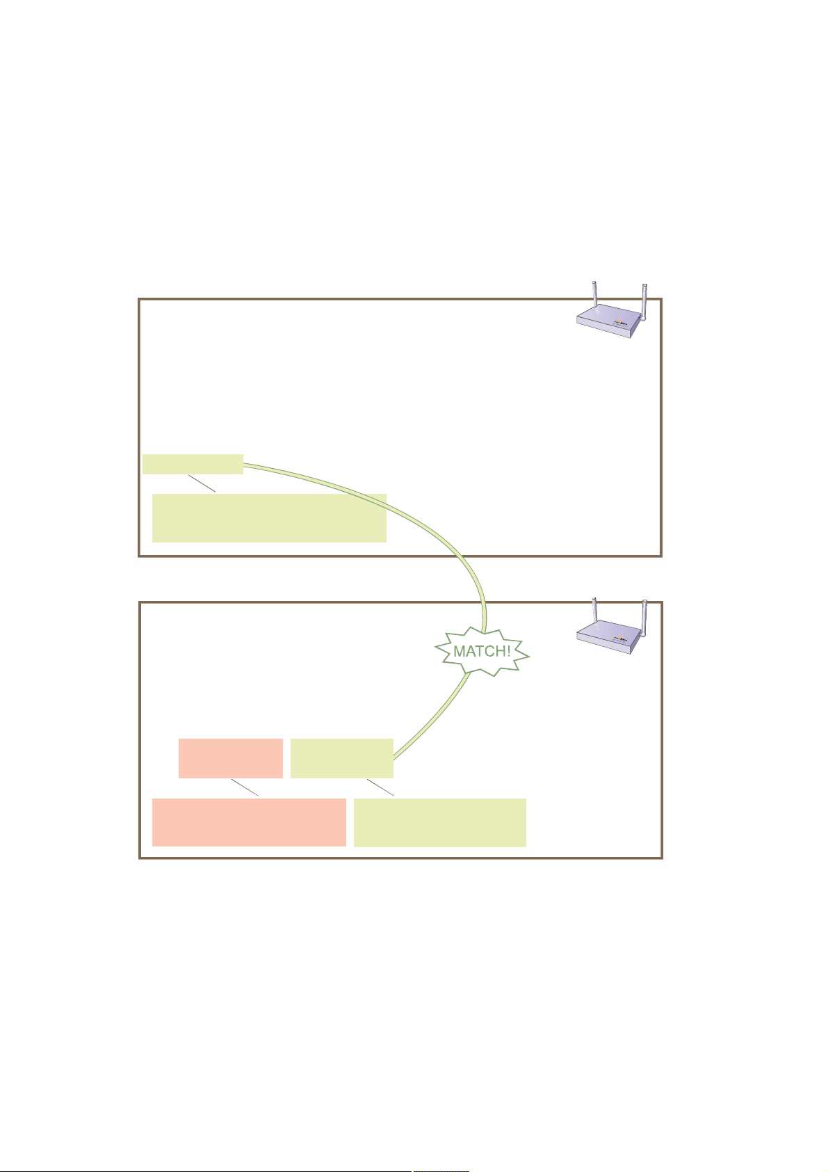
7.To check that the hive members have full data connectivity with each other, associate a client in wireless
network-1 with HiveAP-1 (the SSID "employee" is already defined on clients in wireless network-1; see
"Deploying a Single HiveAP"). Then check if HiveAP-1 forwards the client’s MAC address to the others to store in
their roaming caches.
Яº¬»® ¿--±½·¿¬·²¹ ¿ ©·®»´»-- ½´·»²¬ ©·¬¸ Ш·ª»ЯРупф ´±¹ ·² ¬±
Ш·ª»ЯРуп ¿²¼ »²¬»® ¬¸·- ½±³³¿²¼ж
-¸±© --·¼ »³°´±§»» -¬¿¬·±²-
ݸ¿² ó ½¸¿²²»´ ²«³¾»®ô ÎÍÍ× ó λ½»·ª» Í·¹²¿´ ͬ®»²¹¬¸ ×¼»²¬·º·»®
ßóÓ±¼» ó ß«¬¸»²¬·½¿¬·±² ³±¼»ô Ý·°¸»® ó Û²½®§°¬·±² ³±¼»
ßóÌ·³» ó ß--±½·¿¬»¼ ¬·³»ô ß«¬¸ ó ß«¬¸»²¬·½¿¬»¼
Ó¿½ ß¼¼® ݸ¿² כּ ÎÍÍ× ßóÓ±¼» Ý·°¸»® ßóÌ·³» ÊÔßÒ ß«¬¸
уууууууууууууу уууу уууу уууу уууууу уууууу ууууууууууу уууу уууу
ррпкж½ºи½жлй¾½ п пУ йр ©°¿ ¿»- ½½³рржпнжок п З»-
̸·- ÓßÝ ¿¼¼®»-- ·- º±® ¬¸» ©·®»´»-¿¼¿°¬»® ±º ¬¸» ½´·»²¬ ø±® •-¬¿¬·±²Œ ±® •ÍÌߌ÷
¿--±½·¿¬»¼ ©·¬¸ ¬¸» ÍÍ×Ü •»³°´±§»»Œò
̸»² ´±¹ ·² ¬± Ø·ª»ßÐóî ¿²¼ »²¬»® ¬¸·- ½±³³¿²¼æ
-¸±© ®±¿³·²¹ ½¿½¸»
α¿³·²¹ Ý¿½¸·²¹ Ì¿¾´»æ
ууууууууууууууууууууууууууууууууууууууууууууóóóóó
³¿¨·³«³ ¿¹»±«¬æ ëðð
º´¿¹æ øÔ÷±½¿´ øÎ÷»³±¬»
ууууууууууууууууууууууууууууууууууууууууууууууууу
Ò±ò ßÐ ÍÌß ¿¹» ÐÓÕ º´¿¹
р ррпзжййрржррйр ррпкж½ºи½жлй¾½ ии пнмзттт О
Ø·ª»ßÐóï
Ø·ª»ßÐóî
̸·- ÓßÝ ¿¼¼®»-- ·- º±® ¬¸» ³¹¬ð
·²¬»®º¿½» ±º Ш·ª»ЯРупф ¬¸» ЯР ©·¬¸
©¸·½¸ ¬¸» ©·®»´»-- ½´·»²¬ ¿--±½·¿¬»¼т
Й¸»² §±« -»» ¬¸» УЯЭ ¿¼¼®»-- ±º ¬¸» ©·®»´»-- ½´·»²¬ ¬¸¿¬ ·- ¿--±½·¿¬»¼ ©·¬¸ Ш·ª»ЯРуп ·² ¬¸» ®±¿³·²¹
½¿½¸» ±º Ш·ª»ЯРуоф §±« µ²±© ¬¸¿¬ Ш·ª»ЯРуп ¿²¼ уо ¿®» -«½½»--º«´´§ -»²¼·²¹ ¼¿¬¿ ±ª»® ¬¸» ¾¿½µ¸¿«´ ´·²µт
λ°»¿¬ ¬¸·- ¬± ½±²º·®³ ¬¸¿¬ Ø·ª»ßÐóí ¿´-± ¸¿- ¿ ¾¿½µ¸¿«´ ½±²²»½¬·±² ©·¬¸ ¬¸» ±¬¸»® ³»³¾»®-ò
Deployment Guide 77
̸·- ·- ¬¸» -¿³» ÓßÝ ¿¼¼®»-º±® ¬¸» ½´·»²¬ ø-¬¿¬·±²÷ ¬¸¿¬ §±«
-¿© ´·-¬»¼ ±² Ш·ª»ЯРупт
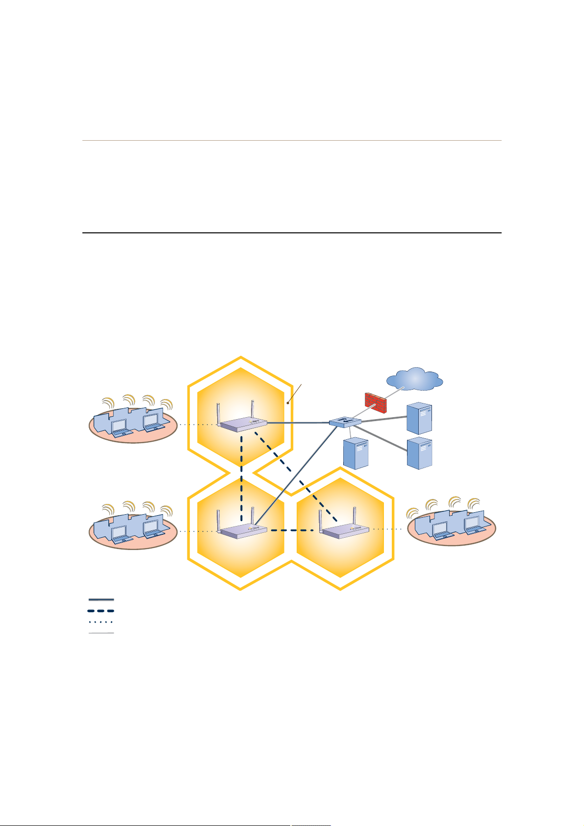
Chapter 6 Deployment Examples (CLI)
Step 4Configure wireless clients
Define the "employee" SSID on all the wireless clients in wireless network-2 and -3. Specify WPA-PSK for network
authentication, AES or TKIP for data encryption, and the preshared key N38bu7Adr0n3.
The setup of hive1 is complete. Wireless clients can now associate with the HiveAPs using SSID "employee" and
access the network. The HiveAPs communicate with each other to share client associations (to support fast roaming)
and routing data (to select optimal data paths).
EXAMPLE 3:USING IEEE 802.1X AUTHENTICATION
In this example, you use a Microsoft AD (Active Directory) server and a RADIUS server to authenticate wireless
network users. To accomplish this, you make the following modifications to the hive set up in "Deploying a Hive":
• Configure settings for the RADIUS server on the HiveAPs
• Change the SSID parameters on the HiveAPs and wireless clients to use IEEE 802.1X
The basic network design is shown in Figure3.
Figure 3 Hive and 802.1X Authentication
Wireless Network-1
Wireless Network-2
Wired Hive Backhaul Communications
Wireless Hive Backhaul Communications
Wireless Network Access Connections
Wired Ethernet Network Connections
Hive1
HiveAP-1
HiveAP-2HiveAP-3
The HiveAPs receive PEAP (Protected EAP) authentication requests
from clients and forward them inside RADIUS authentication packets
to the RADIUS server at 10.1.1.10. The RADIUS server is in turn
linked to the database of the Active Directory server on which all the
user accounts have previously been created and stored.
Firewall
Switch
DHCP
Server
Internet
RADIUS Server
10.1.1.10
Active Directory
Server
Wireless Network-3
78 Aerohive

Note: This example assumes that the RADIUS and AD servers were previously configured and populated with user
accounts that have been in use on a wired network (not shown). The only additional configuration on these
servers is to enable the RADIUS server to accept authentication requests from the HiveAPs.
Step 1Define the RADIUS server on the HiveAP-1
Configure the settings for the RADIUS server (IP address and shared secret) on HiveAP-1.
aaa radius-server first 10.1.1.10 shared-secret s3cr3741n4bl0X
The IP address of the RADIUS server is 10.1.1.10, and the shared secret that HiveAP-1 and the RADIUS
server use to authenticate each other is "s3cr3741n4b10X". You must also enter the same shared secret
on the RADIUS server when you define the HiveAPs as access devices (see step5).
Step 2Change the SSID on HiveAP-1
1.Change the authentication method in the SSID.
ssid employee security protocol-suite wpa-auto-8021x
save config
The protocol suite requires WPA (Wi-Fi Protected Access) or WPA2 security protocol for authentication
and key management, AES or TKIP encryption, and user authentication through IEEE 802.1X.
2.Enter the show interface mgt0 command and note the dynamically assigned IP address of the mgt0
interface. You need to know this address to define HiveAP-1 as an access device on the RADIUS server in step5.
exit
Step 3Configure HiveAP-2 and HiveAP-3
1.Log in to HiveAP-2 through its console port.
2.Configure HiveAP-2 with the same commands that you used for HiveAP-1:
aaa radius-server first 10.1.1.10 shared-secret s3cr3741n4bl0X
ssid employee security protocol-suite wpa-auto-8021x
save config
Note: Although all HiveAPs in this example use the same shared secret, they can also use different secrets.
3.Enter the show interface mgt0 command to learn its IP address. You need this address for step5.
exit
4.Log in to HiveAP-3 and enter the same commands.
Step 4Modify the SSID on the wireless clients
Modify the "employee" SSID on all the wireless clients in wireless network-2 and -3. Specify WPA or WPA2 for network
authentication, AES or TKIP for data encryption, and PEAP (Protected EAP) for user authentication.
Deployment Guide 79
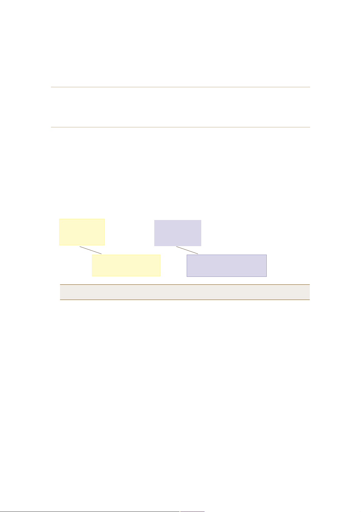
Chapter 6 Deployment Examples (CLI)
Step 5Configure the RADIUS Server to accept authentication requests from the HiveAPs
Log in to the RADIUS server and define the three HiveAPs as access devices. Enter their mgt0 IP addresses and
shared secret.
Step 6Check that clients can form associations and access the network
1.To check that a client can associate with a HiveAP and access the network, open a wireless client application
and connect to the "employee" SSID. Then contact a network resource, such as a web server.
2.Log in to the HiveAP CLI, and check that you can see the MAC address or the associated client and an indication
that the correct SSID is in use by entering the following command:
-¸±© --·¼ »³°´±§»» -¬¿¬·±²-
ݸ¿² ó ½¸¿²²»´ ²«³¾»®ô ÎÍÍ× ó λ½»·ª» Í·¹²¿´ ͬ®»²¹¬¸ ×¼»²¬·º·»®
ßóÓ±¼» ó ß«¬¸»²¬·½¿¬·±² ³±¼»ô Ý·°¸»® ó Û²½®§°¬·±² ³±¼»
ßóÌ·³» ó ß--±½·¿¬»¼ ¬·³»ô ß«¬¸ ó ß«¬¸»²¬·½¿¬»¼
Ó¿½ ß¼¼® ݸ¿² כּ ÎÍÍ× ßóÓ±¼» Ý·°¸»® ßóÌ·³» ÊÔßÒ ß«¬¸
уууууууууууууу уууу уууу уууу уууууу уууууу уууууууу уууу уууу
ррпкж½ºи½жлй¾½ п пУ ки ироп¨ ¿»- ½½³ рржрожнм п З»-
ݸ»½µ ¬¸¿¬ ¬¸» ÓßÝ ¿¼¼®»--
·² ¬¸» ¬¿¾´» ³¿¬½¸»- ¬¸¿¬ ±º
¬¸» ©·®»´»-- ½´·»²¬ ò
Note: You can also enter the following commands to check the association status of a wireless client:
show auth, show roaming cache, and show roaming cache mac <mac_addr>.
The setup for using IEEE 802.1X is complete. Wireless clients can now associate with the HiveAP using SSID
"employee", authenticate themselves through IEEE 802.1X to a RADIUS server, and access the network.
ݸ»½µ ¬¸¿¬ ¬¸» ¿«¬¸»²¬·½¿¬·±² ¿²¼
»²½®§°¬·±² ³±¼»- ³¿¬½¸ ¬¸±-» ·²
¬¸» ÍÍ×Ü -»½«®·¬§ °®±¬±½±´ -«·¬»ò
80 Aerohive

EXAMPLE 4:APPLYING QOS
In this example, you want the hive members to prioritize voice, streaming media, and e-mail traffic. First, you map
distinguishing elements of these traffic types to three Aerohive QoS (Quality of Service) classes:
Class 6: voice traffic from VoIP phones with MAC OUI 00:12:3b (the OUI for all phones in the network)
Voice traffic is very sensitive to delay and cannot tolerate packet loss without loss of voice quality. When
other traffic is competing with voice traffic for bandwidth, it becomes essential to prevent that traffic from
interfering with voice traffic. Because voice traffic for a single call requires very little bandwidth—typically
from 8 to 64 Kbps depending on the voice codec used—a good approach for setting its rate is to calculate
the bandwidth necessary for a limited number of voice calls from a single user’s computer, softphone, or
handset and then multiply that by the potential number of concurrent VoIP users.
Class 5: streaming media using the MMS (Microsoft Media Server) protocol on TCP port 1755
Although streaming media is also time sensitive, streaming media software for both clients and servers
offers limited buffering to prevent choppy sounds and pixelated video when network congestion occurs.
Because congestion for more than a few seconds can adversely effect streaming media, it is important to
assign this type of traffic a higher priority than other types, but its priority should be lower than that for
voice, which is even more sensitive to delay.
Class 3: data traffic for e-mail using the following protocols:
SMTP (Simple Mail Transfer Protocol) on TCP port 25
POP3 (Post Office Protocol version 3) on TCP port 110
Then you create classifier profiles that reference these traffic-to-class mappings. You bind the profiles to the
wifi0.1 and eth0 interfaces so that hive members map the traffic matching these profiles that arrives at these
interfaces to the proper Aerohive classes.
You next define a QoS policy that defines how the hive members prioritize and process the traffic mapped to
Aerohive classes 6, 5, and 3. The QoS policy (named "voice") is shown in Figure4 on page82 and has these settings:
Class 6 (voice)
Forwarding: strict (Hive members forward traffic mapped to this class immediately without queuing it.)
Maximum rate for all class 6 traffic: 512 Kbps, which supports eight concurrent 64-Kbps VoIP calls:
512 Kbps maximum rate ÷ 64 Kbps/call = 8 calls maximum (more if the codec provides greater compression)
Class 5 (streaming media)
Forwarding: WRR (weighted round robin) with a weight of 90
By assigning class 5 a higher weight (90) than class 3 and 2 weights (class 3 = 60, class 2 = 30), you give
streaming media roughly a 3:2 priority over class 3 traffic and a 3:1 priority over class 2 traffic.
Maximum traffic rate for all class 5 traffic: 20,000 Kbps
You increase the bandwidth available for streaming media when there is no competition for it (the
default rate for class 5 is 10,000 Kbps). However, you do not set the maximum rate (54,000 Kbps) to
ensure that streaming media does not consume all available bandwidth even if it is available.
Class 3 (e-mail)
Forwarding: WRR with a weight of 60
To help ensure that e-mail traffic remains flowing even when other types of data traffic compete with it
for available bandwidth, you elevate its priority by mapping SMTP and POP3 traffic to class 3 and giving
that class a higher weight (60) than the weight for class 2 traffic (30).
Maximum traffic rate for all class 3 traffic: 54,000 Kbps (the default)
Deployment Guide 81

Chapter 6 Deployment Examples (CLI)
Note: The HiveAP assigns all traffic that you do not specifically map to an Aerohive class to class 2, which by
default uses WRR with a weight of 30 and a rate of 54,000 Kbps.
Figure 4 QoS Policy "voice" for Voice, Streaming Media, and Data
Ï±Í Ð±´·½§æ •ª±·½»Œ
ʱ·½»
̸» °±´·½§ ¿--·¹²- ¬¸» ¸·¹¸»-¬ °®·±®·¬§ ¬± ª±·½» ¬®¿ºº·½ ø½´¿-- ê÷ò Ú±® »¿½¸ ª±·½» -»--·±² «° ¬±
ëïî Õ¾°-ô ¸·ª» ³»³¾»®- °®±ª·¼» •-¬®·½¬Œ º±®©¿®¼·²¹å ¬¸¿¬ ·-ô ¬¸»§ º±®©¿®¼ ¬®¿ºº·½ ·³³»¼·¿¬»´§
©·¬¸±«¬ ¯«»«·²¹ ·¬ò
¯±- °±´·½§ ª±·½» ¯±- ê -¬®·½¬ ëïî ð
ͬ®»¿³·²¹
Ó»¼·¿
Ю»½¿«-» -¬®»¿³·²¹ ³»¼·¿ ш½´¿-- лч ²»»¼- ³±®» ¾¿²¼©·¼¬¸ ¬¸¿² ª±·½» ¼±»-ф ¬¸» °±´·½§
¼»º·²»- ¿ ¸·¹¸»® º±®©¿®¼·²¹ ®¿¬» º±® ·¬ж орфррр Х¾°-т Ч¬ -±®¬- -¬®»¿³·²¹ ³»¼·¿ ·²¬± º±®©¿®¼·²¹
¯«»«»- «-·²¹ ¬¸» ЙОО ш©»·¹¸¬»¼ ®±«²¼ ®±¾·²ч ³»½¸¿²·-³т Ч¬ ¿´-± °®·±®·¬·¦»- -¬®»¿³·²¹ ³»¼·¿
¾§ ¿--·¹²·²¹ ¿ ¸·¹¸»® ©»·¹¸¬ шзрч ¬¸¿² ·¬ ¿--·¹²- ¼¿¬¿ ¬®¿ºº·½ ш½´¿-- н г крф ½´¿-- о г нрчт
Ü¿¬¿
ö DZ« ¼± ²±¬ ²»»¼ ¬± »²¬»® ¬¸·- ½±³³¿²¼ ¾»½¿«-» ·¬ ¶«-¬ -»¬- ¬¸» ¼»º¿«´¬
ª¿´«»- º±® ½´¿-- îò ׬ ·- -¸±©² ¬± °®±ª·¼» ½±²¬®¿-¬ ©·¬¸ ¬¸» °®»ª·±«- ½±³³¿²¼ò
М¸» °±´·½§ -±®¬- ½´¿-- н ¿²¼ о ¬®¿ºº·½ ·²¬± º±®©¿®¼·²¹ ¯«»«»- «-·²¹ ЙОО ¿²¼ ¼»º·²»- ¬¸»
¸·¹¸»-¬ º±®©¿®¼·²¹ ®¿¬»ж лмфррр Х¾°-т Ч¬ ¹·ª»- ½´¿-- н шº±® »у³¿·´ °®±¬±½±´- НУМР ¿²¼ РСРнч
¿ ¸·¹¸»® ЙОО ©»·¹¸¬ шкрч -± ¬¸¿¬ ¬¸» Ш·ª»ЯР ¯«»«»- ³±®» »у³¿·´ ¬®¿ºº·½ ·² °®±°±®¬·±² ¬± ±¬¸»®
¬§°»- ±º ¬®¿ºº·½ ·² ½´¿-- оф ©¸·½¸ ¸¿- ¿ ©»·¹¸¬ ±º нр ¾§ ¼»º¿«´¬т Я- ¿ ®»-«´¬ф »у³¿·´ ¬®¿ºº·½ ¸¿- ¿
¾»¬¬»® ½¸¿²½» ±º ¾»·²¹ º±®©¿®¼»¼ ¬¸¿² ±¬¸»® ¬§°»- ±º ¬®¿ºº·½ ©¸»² ¾¿²¼©·¼¬¸ ·- -½¿®½»т
Ý´¿-- î ·- º±® ¿´´ ¬§°»- ±º ¬®¿ºº·½ ²±¬ ³¿°°»¼ ¬± ¿² ß»®±¸·ª» ½´¿--‰-«½¸ ¿- ØÌÌÐ º±® »¨¿³°´»ò
¯±- °±´·½§ ª±·½» ¯±- л ©®® орррр зр
¯±- °±´·½§ ª±·½» ¯±- н ©®® лмррр кр
¯±- °±´·½§ ª±·½» ¯±- о ©®® лмррр нрö
Note: This example assumes that the RADIUS and AD servers were previously configured and populated with user
accounts and have been serving a wired network (not shown). The only additional configuration is to
enable the RADIUS server to accept authentication requests from the HiveAPs.
Finally, you create a user profile "employee-net" and apply the QoS policy "voice" to the user profile on each hive
member. You also configure the RADIUS server to return attributes in its authentication responses to indicate the
user group to which the hive members then assign users.
82 Aerohive

Step 1Map traffic types to Aerohive QoS classes on HiveAP-1
1.Map the MAC OUI (organizational unit identifier) of network users’ VoIP phones to Aerohive class 6.
qos classifier-map oui 00:12:3b qos 6
In this example, all network users use VoIP phones from the same vendor whose OUI (that is, the MAC
address prefix ) is 00:12:3b. When HiveAP-1 receives traffic from a client whose source MAC address
contains this OUI, it assigns it to Aerohive class 6.
2.Define the custom services that you need.
service mms tcp 1755
service smtp tcp 25
service pop3 tcp 110
The MMS (Microsoft Media Server) protocol can use several transports (UDP, TCP, and HTTP). However,
for a HiveAP to be able to map a service to an Aerohive QoS class, it must be able to identify that
service by a unique characteristic such as a static destination port number or a nonstandard protocol
number. Unlike MMS/UDP and MMS/HTTP, both of which use a range of destination ports, MMS/TCP uses
the static destination port 1755, which a HiveAP can use to map the service to an Aerohive class.
Therefore, you define a custom service for MMS using TCP port 1755. You also define custom services for
SMTP and POP3 so that you can map them to Aerohive class 3. By doing so, you can prioritize e-mail
traffic above other types of traffic that the HiveAP assigns to class 2 by default.
3.Map services to Aerohive classes.
qos classifier-map service mms qos 5
qos classifier-map service smtp qos 3
qos classifier-map service pop3 qos 3
Unless you map a specific service to an Aerohive QoS class, a HiveAP maps all traffic to class 2. In this
example, you prioritize voice, media, and e-mail traffic by assigning them to higher QoS classes than
class 2, and then by defining the forwarding and weighting mechanisms for each class (see step3).
Step 2Create profiles to check traffic arriving at interfaces on HiveAP-1
1.Define two classifier profiles for the traffic types "mac" and "service".
qos classifier-profile wifi0.1-voice mac
qos classifier-profile wifi0.1-voice service
qos classifier-profile eth0-voice mac
qos classifier-profile eth0-voice service
Classifier profiles define which components of incoming traffic HiveAP-1 checks. Because you specify
"mac" and "service", it checks the MAC address in the Ethernet frame header and the service type (by
protocol number in the IP packet header and port number in the transport packet header). If it detects
traffic matching a classifier-map, it maps it to the appropriate Aerohive class. However, before this can
happen, you must first associate the profiles with the interfaces that will be receiving the traffic that
you want checked. This you do with the next two commands.
Deployment Guide 83

Chapter 6 Deployment Examples (CLI)
2.Associate the classifier profiles with the wifi0.1 subinterface and the eth0 interface so that HiveAP-1 can
classify incoming traffic arriving at these two interfaces.
interface wifi0.1 qos-classifier wifi0.1-voice
interface eth0 qos-classifier eth0-voice
By creating two QoS classifiers and associating them with the wifi0.1 and eth0 interfaces, HiveAP-1 can
classify traffic flowing in both directions for subsequent QoS processing; that is, it can classify traffic
flowing from the wireless LAN to the wired LAN, and from the wired LAN to the wireless LAN.
Note: If the surrounding network employs the IEEE 802.11p QoS classification system (for wired network
traffic) or 802.11e (for wireless network traffic), you can ensure that HiveAP-1 checks for them by
entering these commands:
qos classifier-profile eth0-voice 8021p
qos classifier-profile wifi0.1-voice 80211e
Step 3Apply QoS on HiveAP-1
1.Create a QoS policy.
qos policy voice qos 5 wrr 20000 90
qos policy voice qos 3 wrr 54000 60
By default, a newly created QoS policy attempts to forward traffic mapped to classes 6 and 7
immediately upon receipt. This immediate forwarding of received traffic is called "strict" forwarding. To
assign strict forwarding to VoIP traffic from phones whose MAC OUI is mapped to class 6, you simply
retain the default (top priority) settings for class 6 traffic. For classes 5 and 3, you limit the rate of
traffic and set WRR (weighted round robin) weights so that the HiveAP can control how to put the
rate-limited traffic into forwarding queues. You use the default settings for class 2 traffic.
When you enter any one of the above commands, the HiveAP automatically sets the maximum
bandwidth for all members of the user group to which you later apply this policy and the bandwidth for
any individual group member. You leave the maximum traffic rate at the default 54,000 Kbps for the
user group. You also leave the maximum bandwidth for a single user at 54,000 Kbps, so that if a single
user needs all the bandwidth and there is no competition for it, that user can use it all.
Also by default, the traffic rate for this policy has a weight of 10. At this point, because this is the only
QoS policy, the weight is inconsequential. If there were other QoS policies, then their weights would
help determine how the HiveAP would allocate the available bandwidth.
The QoS policy that you define is shown in Figure5 on page85. Note that although you did not configure
settings for Aerohive QoS classes 0, 1, 2, 4, and 7, the policy applies default settings to them. The HiveAP
assigns all traffic that you do not specifically map to an Aerohive class to class 2, which uses WRR with a weight
of 30 and a rate of 54,000 Kbps by default. Because nothing is mapped to classes 0, 1, 4, and 7, their settings
are irrelevant.
84 Aerohive
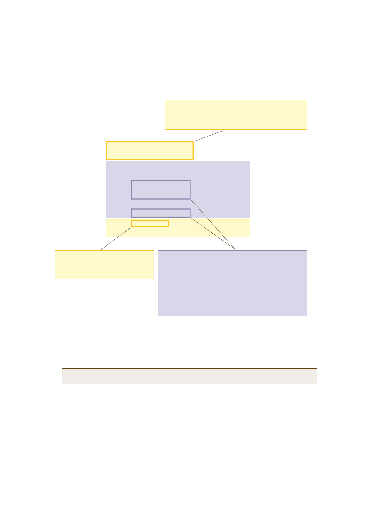
Figure 5 QoS Policy "voice"
̸» «-»® °®±º·´» ®¿¬» ¼»º·²»- ¬¸» ¬±¬¿´ ¿³±«²¬ ±º ¾¿²¼©·¼¬¸
º±® ¿´´ «-»®- ¬± ©¸·½¸ ¬¸·- °±´·½§ ¿°°´·»-ò ̸» «-»® ®¿¬»
¼»º·²»- ¬¸» ³¿¨·³«³ ¿³±«²¬ º±® ¿²§ -·²¹´» «-»®ò ̸» «-»®
®¿¬» ½¿² ¾» »¯«¿´ ¬± ¾«¬ ²±¬ ¹®»¿¬»® ¬¸¿² ¬¸» «-»® °®±º·´» ®¿¬»ò
-¸±© ¯±- °±´·½§ ª±·½»
ª±·½» «-»® °®±º·´» ®¿¬»жлмрррµ¾°- «-»® °®±º·´» ©»·¹¸¬жпр
«-»® ®¿¬» ´·³·¬жлмрррµ¾°-
½´¿--жр ³±¼»ж©®® ©»·¹¸¬жпр ´·³·¬жлмрррµ¾°-
½´¿--жп ³±¼»ж©®® ©»·¹¸¬жор ´·³·¬жлмрррµ¾°-
½´¿--жо ³±¼»ж©®® ©»·¹¸¬жнр ´·³·¬жлмрррµ¾°-
½´¿--жн ³±¼»ж©®® ©»·¹¸¬жкр ´·³·¬жлмрррµ¾°-
½´¿--жм ³±¼»ж©®® ©»·¹¸¬жлр ´·³·¬жлмрррµ¾°-
½´¿--жл ³±¼»ж©®® ©»·¹¸¬жзр ´·³·¬жоррррµ¾°-
½´¿--æê ³±¼»æ-¬®·½¬ ©»·¹¸¬æð ´·³·¬æëïîµ¾°-
½´¿--æé ³±¼»æ-¬®·½¬ ©»·¹¸¬æð ´·³·¬æëïîµ¾°-
̸» º±®©¿®¼·²¹ ³±¼» º±® ½´¿-- ê øª±·½»÷
·- -¬®·½¬ò ̸» Ø·ª»ßÐ º±®©¿®¼- °¿½µ»¬¾»´±²¹·²¹ ¬± ¬¸·- ½´¿-- ·³³»¼·¿¬»´§
©·¬¸±«¬ ¯«»«·²¹ ¬¸»³ò
2.Create a user profile and apply the QoS policy to it.
user-profile employee-net group-id 2 qos-policy voice
You apply the QoS policy "voice" to all users belonging to the user-profile "employee-net" with group ID
2. On the RADIUS server, you must configure group ID 2 as one of the RADIUS attributes that the RADIUS
server returns when authenticating users (see step5).
Note: When HiveAP-1 does not use RADIUS for user authentication, you must assign the user profile to an
SSID. To do that, use the following command: ssid employee default-user-profile-id 2
save config
exit
̸» º±®©¿®¼·²¹ ³±¼» º±® ½´¿-- ë ø-¬®»¿³·²¹ ³»¼·¿÷ ¿²¼ î ó í
ø¼¿¬¿÷ ·- ÉÎÎ ø©»·¹¸¬»¼ ®±«²¼ ®±¾·²÷ò ̸» Ø·ª»ßÐ º±®©¿®¼¬®¿ºº·½ ¾»´±²¹·²¹ ¬± ¬¸»-» ½´¿--»- ¾§ °«¬¬·²¹ ¬¸»³ ·²¬±
º±®©¿®¼·²¹ ¯«»«»-ò ̸» ©»·¹¸¬- ¼»¬»®³·²» ¸±© ³¿²§ ¾·¬- °»®
-»½±²¼ ¹± ·²¬± »¿½¸ ¯«»«»ò Ú±® »ª»®§ íð ¾·¬- ¬¸¿¬ ¬¸» Ø·ª»ßÐ
¯«»«»- º±® ½´¿-- îô ·¬ ¯«»«»- ¿°°®±¨·³¿¬»´§ êð ¾·¬- º±® ½´¿-- íô
¿²¼ çð ¾·¬- º±® ½´¿-- ëò ̸»-» ¿³±«²¬- ¿®» ¿°°®±¨·³¿¬·±²¾»½¿«-» ¬¸» Ø·ª»ßÐ ¿´-± ¸¿- ¿² ·²¬»®²¿´ -»¬ ©»·¹¸¬- º±® ¬®¿ºº·½
·² ¼·ºº»®»²¬ ½´¿--»- ¬¸¿¬ -µ»©- º±®©¿®¼·²¹ ·² º¿ª±® ±º ¬®¿ºº·½
¾»´±²¹·²¹ ¬± ¸·¹¸»® ½´¿--»-ò
Deployment Guide 85

Chapter 6 Deployment Examples (CLI)
Step 4Configure HiveAP-2 and HiveAP-3
1.Log in to HiveAP-2 through its console port.
2.Configure HiveAP-2 with the same commands that you used for HiveAP-1:
qos classifier-map oui 00:12:3b qos 6
service mms tcp 1755
service smtp tcp 25
service pop3 tcp 110
qos classifier-map service mms qos 5
qos classifier-map service smtp qos 3
qos classifier-map service pop3 qos 3
qos classifier-profile wifi0.1-voice mac
qos classifier-profile wifi0.1-voice service
qos classifier-profile eth0-voice mac
qos classifier-profile eth0-voice service
interface wifi0.1 qos-classifier wifi0.1-voice
interface eth0 qos-classifier eth0-voice
qos policy voice qos 5 wrr 20000 90
qos policy voice qos 3 wrr 54000 60
user-profile employee-net group-id 2 qos-policy voice
save config
exit
3.Log in to HiveAP-3 and enter the same commands.
Step 5Configure RADIUS server attributes
1.Log in to the RADIUS server and define the three HiveAPs as RADIUS clients.
2.Configure the following attributes for the realm to which the wireless user accounts in network-1, -2, and -3
belong:
• Tunnel Type = GRE (value = 10)
• Tunnel Medium Type = IP (value = 1)
• Tunnel Private Group ID = 2
The RADIUS server returns the above attributes for all wireless users it authenticates from network-1, -2, and -3.
The HiveAP uses the combination of returned RADIUS attributes to assign users to the user group 2 ("employee-net").
It does not use them to create a GRE tunnel, which the tunnel type attribute might lead you to think.
When there is more traffic than available bandwidth, the HiveAP applies the "voice" policy. It performs strict
forwarding for voice and uses a WRR (weighted round robin) scheduling discipline for directing streaming media and
data traffic to queues to await forwarding. The QoS configuration is complete.
86 Aerohive

CLI COMMANDSFOR EXAMPLES
CLI COMMANDSFOR EXAMPLES
This section includes all the CLI commands for configuring the HiveAPs in the previous examples. The CLI
configurations are presented in their entirety (without explanations) for easy copying and pasting. Simply copy the
blocks of text for configuring the HiveAPs in each example and paste them at the command prompt.
Note: The following sections omit optional commands, such as changing the login name and password, and
commands used to check a configuration.
Commands for Example 1
Enter the following commands to configure the SSID "employee" on the single HiveAP in "Deploying a Single HiveAP"
on page70:
ssid employee
ssid employee security protocol-suite wpa-auto-psk ascii-key N38bu7Adr0n3
interface wifi0.1 ssid employee
save config
Commands for Example 2
Enter the following commands to configure three HiveAPs as members of "hive1" in "Deploying a Hive" on page73:
HiveAP-1
hive hive1
hive hive1 password s1r70ckH07m3s
interface mgt0 hive hive1
save config
HiveAP-2
ssid employee
ssid employee security protocol-suite wpa-auto-psk ascii-key N38bu7Adr0n3
interface wifi0.1 ssid employee
hive hive1
hive hive1 password s1r70ckH07m3s
interface mgt0 hive hive1
save config
Deployment Guide 87

Chapter 6 Deployment Examples (CLI)
HiveAP-3
ssid employee
ssid employee security protocol-suite wpa-auto-psk ascii-key N38bu7Adr0n3
interface wifi0.1 ssid employee
hive hive1
hive hive1 password s1r70ckH07m3s
interface mgt0 hive hive1
save config
Commands for Example 3
Enter the following commands to configure the hive members to support IEEE 802.1X authentication in "Using IEEE
802.1X Authentication" on page78:
HiveAP-1
aaa radius-server first 10.1.1.10 shared-secret s3cr3741n4bl0X
ssid employee security protocol-suite wpa-auto-8021x
save config
HiveAP-2
aaa radius-server first 10.1.1.10 shared-secret s3cr3741n4bl0X
ssid employee security protocol-suite wpa-auto-8021x
save config
HiveAP-3
aaa radius-server 10.1.1.10 shared-secret s3cr3741n4bl0X
ssid employee security protocol-suite wpa-auto-8021x
save config
88 Aerohive

CLI COMMANDSFOR EXAMPLES
Commands for Example 4
Enter the following commands to configure the hive members to apply QoS (Quality of Service) to voice, streaming
media, and data traffic in "Applying QoS" on page81:
HiveAP-1
qos classifier-map oui 00:12:3b qos 6
service mms tcp 1755
service smtp tcp 25
service pop3 tcp 110
qos classifier-map service mms qos 5
qos classifier-map service smtp qos 3
qos classifier-map service pop3 qos 3
qos classifier-profile wifi0.1-voice mac
qos classifier-profile wifi0.1-voice service
qos classifier-profile eth0-voice mac
qos classifier-profile eth0-voice service
interface wifi0.1 qos-classifier wifi0.1-voice
interface eth0 qos-classifier eth0-voice
qos policy voice qos 5 wrr 20000 90
qos policy voice qos 3 wrr 54000 60
user-profile employee-net group-id 2 qos-policy voice
save config
HiveAP-2
qos classifier-map oui 00:12:3b qos 6
service mms tcp 1755
service smtp tcp 25
service pop3 tcp 110
qos classifier-map service mms qos 5
qos classifier-map service smtp qos 3
qos classifier-map service pop3 qos 3
qos classifier-profile wifi0.1-voice mac
qos classifier-profile wifi0.1-voice service
qos classifier-profile eth0-voice mac
Deployment Guide 89

Chapter 6 Deployment Examples (CLI)
qos classifier-profile eth0-voice service
interface wifi0.1 qos-classifier wifi0.1-voice
interface eth0 qos-classifier eth0-voice
qos policy voice qos 5 wrr 20000 90
qos policy voice qos 3 wrr 54000 60
user-profile employee-net group-id 2 qos-policy voice
save config
HiveAP-3
qos classifier-map oui 00:12:3b qos 6
service mms tcp 1755
service smtp tcp 25
service pop3 tcp 110
qos classifier-map service mms qos 5
qos classifier-map service smtp qos 3
qos classifier-map service pop3 qos 3
qos classifier-profile wifi0.1-voice mac
qos classifier-profile wifi0.1-voice service
qos classifier-profile eth0-voice mac
qos classifier-profile eth0-voice service
interface wifi0.1 qos-classifier wifi0.1-voice
interface eth0 qos-classifier eth0-voice
qos policy voice qos 5 wrr 20000 90
qos policy voice qos 3 wrr 54000 60
user-profile employee-net group-id 2 qos-policy voice
save config
90 Aerohive
 Loading...