

Page 1
For the very latest specifications visit www.aeroflex.com
WWiitthh iittss lleevveell ooff ppeerrffoorrmmaannccee,, tthhiiss ccoommppaacctt ggeenneerraall ppuurrppoossee ssiiggnnaall ggeenneerraattoorr ddeelliivveerrss oouuttssttaannddiinngg
vvaalluuee ffoorr mmoonneeyy..
Signal Sources
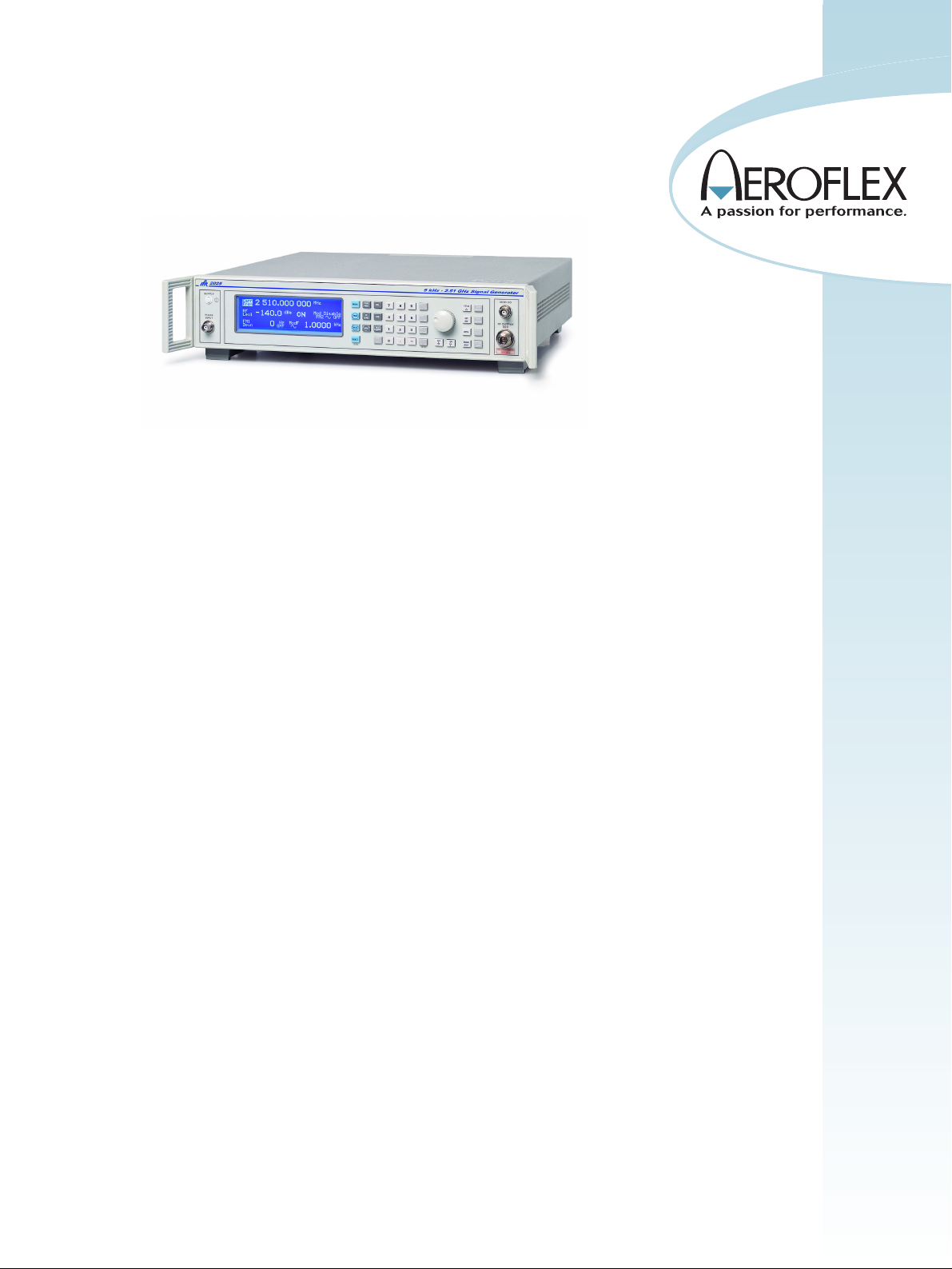
2023A/B, 2025 Signal Generators
• Wide frequency coverage:-
9 kHz to 1.2 GHz (2023A)
9 kHz to 2.05 GHz (2023B)
9 kHz to 2.51 GHz (2025)
• Excellent spectral purity
• Linear and logarithmic sweep mode
• RPP to 50 W
• Sine, triangular and square wave two
tone modulation source
• RS-232 and GPIB control
• Comprehensive modulation:AM, FM, ∅ M , Pulse & FSK
• 3.9 kHz Bessel filtered FSK
• Optional +25 dBm RF output
• SINAD Measurement Option
The 2023A/B and 2025 signal generators are
portable and lightweight, offering carrier frequencies from 9 kHz to 1.2 GHz (2023A), 9 kHz to
2.05 GHz (2023B) and 9 kHz to 2.51 GHz (2025)
with a wide choice of modulation modes.
The instruments are suitable for a wide range of
applications in laboratory, production, and maintenance environments.
The GPIB facility allows the unit to be included in
ATE systems for faster manufacturing throughput.
An RS-232 interface is provided with a command
set in common with the GPIB to simplify remote
control of the signal generator in basic test systems or via a modem.
Operation
Front panel control is achieved through a flexible combination of
keyboard selection, cursor selection and a rotary control in conjunction with a clear and intuitive menu presentation on a bright panel
display. This ensures the instrument can be set up into any desired
mode of operation quickly and simply.
Frequency Selection
Frequency resolution of 1 Hz across the complete frequency range of
1.2 GHz, 2.05 GHz or 2.51 GHz ensures adequate resolution to
characterize narrow band communication systems and components.
RF Output
Peak RF output levels of between +13 dBm and -140 dBm can be set
accurately with a resolution of 0.1 dB. An attenuator hold function
allows control of the RF output without introducing RF level
dropouts from the step attenuator to facilitate testing of receiver
squelch systems, and during EMI investigations. A RF level limit
can be set to limit the output power to avoid damage to external,
power sensitive devices. RF level offsets up to ±15 dB can be applied
to counter the effects of test system losses etc. A carrier ON/OFF
key is provided to completely disable the output.
50 W Protection
An electronic trip protects the generator output against reverse
power of up to 50 W from a source with a VSWR’s of up to 5:1, preventing damage to output circuits if a RF transmitter or DC power
supply is accidentally applied to the output connector. This feature
contributes to long service life and low cost of ownership.
Size and Weight
The 2023A/B and 2025 occupy a full rack width, but only 2 units high
to minimize rack occupancy in manufacturing and test systems and
Page 2
for instrument stacks in benchtop use.
The low weight of the product makes it ideal for portable applications
within maintenance environments.
Spectral Purity
Measurement of receiver selectivity and ultimate signal to noise ratio
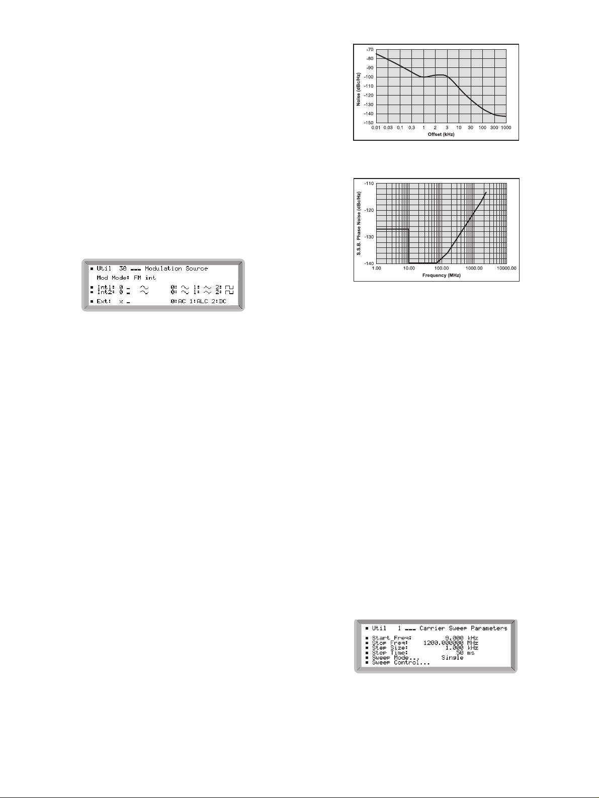
requires good spectral purity. The 2023A/B and 2025 have a low
residual FM of typically 3 Hz and a commendable sideband noise of
typically -121 dBc/Hz at 1 GHz, (20 kHz offset) to allow demanding
measurements to be made at an affordable cost. Good close in phase
noise is also achieved with results at 100 Hz offsets typically <85 dBc.
Modulation
Comprehensive amplitude, frequency, phase, FSK and pulse modulation facilities are provided for testing all types of receivers. A MOD
ON/OFF key simplifies the testing of signal to noise ratio.
Amplitude and Pulse Modulation
Amplitude modulation with a 1 dB band-width of 30 kHz and modulation depths of up to 99.9% with a resolution of 0.1% ensures the
generator is suitable for testing AM systems and undertaking EMC
immunity measurements. The standard pulse modulation facility has
an on/off ratio of better than 40 dB and a rise/fall time of less than
10 µs enabling characterization of TDMA or TDD bursts in RF
amplifiers and modules. The internal square wave modulation
source may be used to self pulse modulate the generator for use in
EMI applications.
An optional Fast Pulse modulator improves the on/off ratio to typically >80 dB with rise and fall times of <20 ns.
Frequency and Phase Modulation
With a 1 dB FM bandwidth of 275 kHz and a deviation range of 0 to
12.8 MHz, the 2023A/B and 2025 signal generators offer a wide range
frequency modulation capability. AC or DC coupled FM can be
selected with very low carrier frequency error and drift in the DC coupled mode ideal for testing paging and DCS (Digitally Coded
Squelch) equipment accurately.
The phase modulation facility is ideal for testing narrow band analog
radios with a deviation range of 0 to 10 radians and a 3 dB bandwidth
up to 10 kHz.
Typical SSB Phase noise at 1 GHz (OCXO fitted)
Typical SSB Phase noise at 20 kHz offset
FSK
The generation of 2 level and 4 level FSK signals is possible directly
from external logic inputs. The TTL data is automatically filtered
using a 8th Order 3.9 kHz Bessel filter to reduce spectral spreading,
as required by both ERMES and FLEX™ paging systems. The
required FM deviation is set from the front panel.
Modulation Oscillator
An internal modulation oscillator is provided which is capable of generating one or two tones in the frequency range of 0.01 Hz to 20 kHz.
In addition to a sine wave output, a triangular or square wave is provided. Internal and external modulation sources may be combined to
produce more complex modulation types.
Sweep
The sweep facility of the 2023A/B and 2025 offers linear and logarithmic sweeps. The user can program all sweep parameters including
start and stop frequency, size of step, time per step and a percentage
increment in the case of logarithmic sweep.
The sweep can be paused and the frequency varied by the rotary control to investigate a problem area.
The sweep can be initiated from the keyboard or by a external trigger
input and can be set to single, continuous, stepped or start/stop operation.
The frequency sweep facility is particularly well suited to EMI testing.
During a frequency sweep, the RF level can be altered using the
rotary control to manually correct the level at the output of amplifiers.
The square wave modulation source allows the generation of square
Page 3

For the very latest specifications visit www.aeroflex.com
wave amplitude modulation to simulate the effect of TDMA bursts
from communication systems on devices being tested for EMI.
The optional high RF output power to +25 dBm can eliminate the
need for external amplifiers when using small test cells.
Instrument Stores
The 2023A/B and 2025 signal generators provide extensive storage
facilities for simplifying repetitive tests. Up to 100 carrier frequency
values and 100 complete instrument settings can be saved to nonvolatile stores. Storage is achieved without the need for batteries and
so avoids problems of periodic replacement.
A software protection system ensures that individual stored settings
cannot be accidentally overwritten.
A further 100 volatile stores are available for complete instrument settings. Their contents can be downloaded over GPIB and then
recalled by store number to reduce the time overhead introduced by
the handling of the GPIB protocol.
Sequencing
A software facility allows 9 sequences of stored instrument settings to
be defined. The incrementing facilities can then be used to cycle
through the settings in manually operated test systems or be operated via an external trigger.
Calibration Data
All alignment data, including the internal frequency standard adjustment, is digitally derived and realignment can be undertaken without
removal of external covers, by protected front panel functions or via
the GPIB. Use of digitally stored realignment eliminates the use of
mechanical adjusters to minimize long term drift and vulnerability to
mechanical shock.
Status information is stored, including an identity string (type and
serial number), choice of internal or external standard and GPIB
address.
An elapsed time facility allows the monitoring of the number of hours
the product has been in use. A recommended calibration interval of
2 years helps towards low cost of ownership.
Programming
A GPIB interface is fitted as standard with all functions controllable
over the bus. The protocol and syntax of GPIB commands are
designed in accordance with IEEE 488.2 standard to simplify the generation of ATE programs.
In talk mode, the current settings, instrument status and the identity
string can be read.
A RS-232 interface is fitted as standard with a common command set
to GPIB commands. RS-232 control is particularly suitable for use
with simple external controllers or RF modems when the instrument
is being used in a remote location.
Memory Cloning
The stored settings in one signal generator can be transferred to others without the use of an external controller using the direct interconnection of GPIB or RS-232 interfaces. This facility is particularly useful for duplicating test set ups on manual production lines.
OPTIONS
The standard features of the signal generator can be enhanced by taking advantage of the various options available.
Option 1 - No Attenuator
This option reduces the instrument cost by deleting the internal
attenuator. An RF output range from -2 dBm to +15 dBm is provided and is a very economic solution for applications requiring a local
oscillator.
Option 2 - DC Operation
The DC supply option allows the signal generator to be used in vehicles, remote areas or where the integrity of the AC supply is not guaranteed.
Option 3 - High Power
A high power option is available which extends the RF output up to
+25 dBm ideal for use as a local oscillator or for testing passive and
active components.
Option 4 - High Stability Frequency Standard
An OCXO internal reference can replace the standard TCXO where
improved frequency stability is required.
Option 5 - Rear Panel Connectors
All front panel connectors may be removed and fitted to the rear panel
for use in production racks.
Option 7 and 11 - Fast Pulse Modulator
A pulse modulator suitable for generating fast pulses with high isolation for applications in radar and EMI.
Option 12 - SINAD Measurement
A fully independent high performance SINAD meter with selectable
weighting filters can be fitted for receiver sensitivity measurements.
SSPPEECCIIFFIICCAATTIIOONN
GGEENNEERRAALL DDEESSCCRRIIPPTTIIOONN
The 2023A/B and 2025 cover the frequency range 9 kHz to
1.2 GHz, 2.05 GHz and 2.51 GHz respectively.
The RF output can be amplitude, frequency, phase or pulse modulated. An internal synthesized programmable AF source is capable of
generating single or simultaneous two tone modulation.
GPIB and RS-232 are included as standard to enable remote control
of all functions except the supply switch.
CCAARRRRIIEERR FFRREEQQUUEENNCCYY
Range
9 kHz to 1.2 GHz (2023A)
9 kHz to 2.05 GHz (2023B)
9 kHz to 2.51 GHz (2025)
Resolution
1 Hz
Accuracy
As frequency standard
Page 4

Phase incrementing
The carrier phase can be advanced or retarded in steps as low as
0.09° using the rotary control
RRFF OOUUTTPPUUTT
Range
-140 dBm to +13 dBm, 0.1 dB resolution. When AM is selected, the
maximum RF output level decreases linearly with increasing AM depth
to +7 dBm at 99.9% depth.
RF Level Units
Units may be set to
µ
V, mV, EMF or PD; dB relative to 1 µV 1 mV EMF
or PD; or dBm. Conversion between dB and linear units may be
achieved by pressing the appropriate units key (dB or V,
µ
V, mV.) The
output level can be normalized for 75
Ω
operation with an impedance
converter.
Level Accuracy
(1)
Frequency >-127 dBm >-100 dBm Temp
Coefficient
9 kHz to 1.2 GHz ±0.8 ±0.8 ±0.02 dB/°C
1.2 GHz to 2.05 GHz ±1.4 ±1.2 ±0.03 dB/°C
2.05 GHz to 2.51 GHz ±1.6 ±1.6 ±0.03 dB/°C
(1)
Over range +17°C to +27°C
Attenuator Hold
Selection of Attenuator hold provides for uncalibrated level reduction of
at least 10 dB without the Mechanical Attenuator operating.
VSWR
For output levels less than -5 dBm, output VSWR is less than 1.3:1 for
carrier frequencies up to 1.2 GHz and less than 1.5:1 for carrier frequencies up to 2.51 GHz.
For output levels greater than -5 dBm output VSWR is less than 1.5:1
for all carrier frequencies.
RF Output Connector
50
Ω
type N connector to MIL-PRF-39012
Output Protection
Protected from a source of reverse power up to 50 W from 50 Ωor 25
W from a source VSWR of 5:1. Protection circuit can be reset from the
front panel or via the GPIB/RS-232 interfaces.
SSPPEECCTTRRAALL PPUURRIITTYY
At RF levels up to +7 dBm:
Harmonics
Typically better than -30 dBc for RF levels up to +7 dBm.
Typically better than -25 dBc for RF levels up to +13 dBm.
Sub- and Non-Harmonics (for offsets >3 kHz)
Better than -70 dBc to 1 GHz, better than -64 dBc between 1 and
2.05 GHz better than -60 dBc above 2.05 GHz.
Residual FM (FM off)
Less than 4.5 Hz RMS deviation in a 300 Hz to 3.4 kHz unweighted
bandwidth at 1 GHz.
SSB Phase Noise
Better than -124 dBc/Hz at 20 kHz offset from a carrier frequency of
470 MHz, typically -121 dBc/Hz at 20 kHz offset from a carrier fre-
quency of 1 GHz.
Carrier leakage
Less than 0.5
µ
V PD at the carrier frequency in a two turn 25 mm
diameter loop, 25 mm from the surface of the signal generator.
ΦΦ
M on AM
Typically 0.1 radians at 30% depth at 470 MHz.
MMOODDUULLAATTIIOONN MMOODDEESS
Internal and external modulation can be simultaneously enabled to
allow combined amplitude and frequency (or phase) modulation.
Pulse modulation can be used in combination with the other forms of
modulation from an external pulse source.
FFRREEQQUUEENNCCYY MMOODDUULLAATTIIOONN
Resolution
1 Hz
Deviation
CW Range (MHz) Max Deviation (kHz)
1200 - 2510 12800
600 - 1200 6400
300 - 600 3200
150 - 300 1600
75 - 150 800
37.5 - 75 400
18.75 - 37.5 200
0.009 - 18.75 100
Accuracy at 1 kHz
±4%
Bandwidth (1 dB)
DC to 275 kHz (DC coupled)
10 Hz to 275 kHz (AC coupled)
20 Hz to 275 kHz (AC coupled with ALC)
Group delay
Less than 5
µ
s to 100 kHz
Carrier frequency offset (DC coupled)
Less than 1% of the set frequency deviation
Distortion
<1% at 1 kHz rate for deviations up to 20% of max available deviation, typically 0.1% for deviations of 2% of max available deviation and
<3% at max available deviation
Modulation source
Internal LF generator or external via front panel BNC
FFSSKK
Modes
2 level or 4 level FSK
Data source
External data connected to TRIGGER connector (2 level) or TRIGGER
and PULSE connectors (4 level)
Note with option 7 fitted, rear panel PULSE input is labelled FSK2
Page 5

For the very latest specifications visit www.aeroflex.com
Frequency shift
Settable up to ±100 kHz
Accuracy
As FM deviation accuracy
Timing jitter
±3.2
µ
s
Filter
8th order Bessel, -3 dB at 3.9 kHz
PPHHAASSEE MMOODDUULLAATTIIOONN
Deviation
0 to 10 radians, 3 digits or 0.01 resolution
Accuracy at 1 kHz
±4% of indicated deviation excluding residual phase modulation
3 dB bandwidth
100 Hz to 10 kHz
Distortion
Less than 3% at 10 radians at 1 kHz modulation rate. Typically <0.5%
for deviations up to 1 radian at 1 kHz
Modulation source
Internal LF generator or external via front panel BNC
AAMMPPLLIITTUUDDEE MMOODDUULLAATTIIOONN
FOR CARRIER FREQUENCIES 2 GHZ
Range
0 to 99.9%, 0.1% resolution
Accuracy
±5% of set depth at 1 kHz (at +17°C to 27°C ambient temperature),
temperature coefficient <±0.02%/°C
1 dB bandwidth
DC to 30 kHz (DC coupled)
10 Hz to 30 kHz (AC coupled)
20 Hz to 30 kHz (AC coupled with ALC)
Distortion
<2.5%* at 1 kHz rate for modulation depths up to 80% and <1.5%
at 1 kHz rate for modulation depths up to 30%
*<3.5% for carrier freqs above 500 MHz
Modulation source
Internal LF generator or external via front panel BNC
PPUULLSSEE MMOODDUULLAATTIIOONN
FOR FAST PULSE MODULATOR SEE OPTIONS
Frequency range
32 MHz to 2.51 GHz, useable to 10 MHz
RF output range
Maximum guaranteed output is reduced to +8 dBm
(+20 dBm or +14 dBm with high power option when pulse modulation is selected)
RF level accuracy
When pulse modulation is enabled, adds ±0.5 dB to the RF level
accuracy specification
On/off ratio
Better than 45 dB below 1.2 GHz, better than 40 dB above 1.2 GHz
Rise and fall times
Less than 10
µ
s
Control
Pulse input is on a rear panel BNC with 10 kΩnominal input impedance. A HCT logic 0 (0 V to 0.8 V) turns the carrier off, a HCT logic 1
(2.0 V to 5 V) turns the carrier on. Max safe input is ±15 V
IINNTTEERRNNAALL LLFF GGEENNEERRAATTOORR
Frequency range
0.01 Hz to 20 kHz
Resolution
5 digit
Frequency accuracy
As frequency standard
Distortion
Less than 0.1% THD at 1 kHz
Waveforms
Sine wave to 20 kHz and a triangular or square wave to 3 kHz
Square wave jitter
<6.4
µ
s on any edge
Audio output
The modulation oscillator signal is available on a front panel BNC connector at a level of 2 V RMS EMF from a 600
Ω
source impedance.
EEXXTTEERRNNAALL MMOODDUULLAATTIIOONN
Input on the front panel via BNC connector. 1 V RMS (1.414 V pk)
sine wave for set deviation. Input sensitivity may be optionally specified for 1 V pk (option 10). Input impedance is 100 k
Ω
nominal.
MMOODDUULLAATTIIOONN AALLCC
The external modulation input can be levelled by a peak levelling ALC
system over the input voltage range of 0.5 V to 1.25 V RMS sine
wave.
High and low indicators on the display indicate when the input is outside the levelling range.
SSWWEEEEPP MMOODDEE
Control parameters
Start and stop values of carrier frequency
Linear sweep
Frequency step size of 1 Hz minimum
Logarithmic sweep
Percentage increment of 0.01% to 50% in 0.01% steps
Step time
50 ms to 10 s per step
Page 6

Trigger
A trigger input is available on a rear panel BNC connector and can be
used for single, continuous, start/stop or single step mode.
FFRREEQQUUEENNCCYY SSTTAANNDDAARRDD
TCXO
10 MHz
Temperature Stability
Better than ±7 in 107over the operating range of 0 to 55°C
Ageing rate
Less than ±1 in 106per year
External input
Rear panel BNC connector accepts an external input of 1 MHz or
10 MHz at a level of 220 mV RMS to 1.8 V RMS into 1 k
Ω
Output
Rear panel BNC connector provides an output of 10 MHz at a nominal
level of 2 V pk-pk into 50
Ω
GGEENNEERRAALL
REMOTE CONTROL
GPIB
All functions except the supply switch are remotely programmable
Capabilities
Designed in accordance with IEEE 488.2.
The GPIB interface complies with the following subsets as defined in
IEEE standard 488.1:
SH1, AH1, T6, TE
∅
, L4, LE∅SR1, RL1, PP0, DC1, DT1, C0, E2
RS-232
All functions except the supply switch are remotely programmable
Connector
9 way male D-type
Bit rate
300 to 9600 bits/s
Handshake
Hardware: DTR, RTS, CTS and DSR
Software: XON and XOFF
Electrical
Interface to EIA-232-D
ELECTROMAGNETIC COMPATIBILITY
Conforms with the protection requirements of the EEC Council Directive
89/336/EEC. Conforms with the limits specified in the following standards:
IEC/EN61326-1 : 1997, RF Emission Class B, Immunity Table 1,
Performance Criteria B
SAFETY
Conforms with the requirements of EEC Council Directive 73/72/EEC
(as amended) and the product safety standard IEC/EN 61010-1 :
2001 + C1 : 2002 + C2 : 2003 for class 1 (or 3) portable equipment, for use in a Pollution Degree 2 environment. The instrument is
designed to be operated from an Installation Category 2 or 1 + 2 supply.
RATED RANGE OF USE (Over which full specification is met)
Temperature
0 to 55°C
Humidity
Up to 93% at 40°C
Altitude
Up to 3050 m (10,000 ft)
CONDITIONS OF STORAGE AND TRANSPORT
Temperature
-40°C to +71°C
Humidity
Up to 95% at 40°C
Altitude
Up to 4600 m (15,000 ft)
POWER REQUIREMENTS
AC Supply
100 to 120 V~, 50 - 400 Hz
(Limit 90 - 132 V~, 45 - 440 Hz
210 - 240 V~, 50 - 60 Hz
(Limit 188 - 264 V~, 45 - 66 Hz)
200 VA maximum
CALIBRATION INTERVAL
2 years
DIMENSIONS AND WEIGHT
(over projections but excluding front panel handles)
Height Width Depth Weight
107 mm 419 mm 440 mm <8 kg
OOPPTTIIOONNSS
OPTION 1 - NO ATTENUATOR
(cannot be specified with option 7 or option 3)
Omits the internal step attenuator. Specification as standard instrument with following exceptions:
RF output range
From -2 dBm to +15 dBm. When AM is selected the maximum output
level reduces linearly with AM depth to +9 dBm at maximum AM
depth.
Pulse modulation
Not available with option 1
Output protection
Reverse power protection is not provided
OPTION 2 - DC OPERATION
Allows for operation from an external DC power source in addition to
an AC power source. Specification as standard instrument with the following additions:
DC supply range
11 V to 32 V
AC Supply
100 to 120 V~, 50 - 400 Hz
Page 7

For the very latest specifications visit www.aeroflex.com
(Limit 90 - 132 V~, 45 - 440 Hz
210 - 240 V~, 50 - 60 Hz
(Limit 188 - 264 V~, 45 - 66 Hz)
200 VA maximum
DC consumption
70 W with option 3 not fitted. 95 W with option 3 and 4 fitted.
Rated Range of Use
Temperature
0 to 45°c
OPTION 3 - HIGH POWER
If fast pulse modulation is needed see Option 11
Specifications as standard instrument with the following exceptions:
RF output range
-140 dBm to +25 dBm (Output power is uncalibrated above
+19 dBm for carrier frequencies above 1.2 GHz and above
+14 dBm above 2.4 GHz). Maximum output is reduced by 5 dB
when standard pulse modulation is selected and/or by up to 6 dB
dependent upon set AM depth.
RF Level Accuracy Above +7 dBm
(over temperature range 17°C to 27°C)
Frequency Accuracy Temp Coeff
9 kHz to 1.2 GHz ±1 dB <23 dBm <±0.02 dB/°C
±1.5 dB<25 dBm
1.2 GHz to 2.5 GHz ±2 dB <±0.03 dB/°C
Harmonics
Typically better than -25 dBc for levels 6 dB below the maximum specified output
Amplitude Modulation (for RF levels from +7 dBm to +18 dBm)
Carrier frequency <500 MHz
Standard depth and distortion spec applies
Carrier frequency 500 MHz to 2 GHz
Accuracy (from +17°C to +27°C ambient, temperature coefficient
<±0.02%/°C)
±7.5% of set depth at 1 kHz mod rate
Distortion (at 1 kHz mod rate)
<5% up to 80% depth
<2.5% up to 30% depth
OPTION 4 - HIGH STABILITY FREQUENCY STANDARD
Replaces the internal TCXO with a high stability OCXO. Specification as
standard instrument with the following exceptions:
Ageing rate
±2.5 in 107per year, ±5 in 109per day after 2 months continuous
use
Stability
Better than ±5 in 108over the temperature range 0 to 50°C
Warm up time
Within 2 in 107of final frequency 10 minutes after switch on at a
temperature of 20°C
OPTION 5 - REAR PANEL CONNECTORS
RF output, modulation input and LF output connectors are transferred
to the rear panel. The signal generator specification is not altered.
OPTION 7 - FAST PULSE MODULATOR
With option 7 fitted, a BNC Pulse input connector is fitted to the front
panel and the existing front panel LF output connector becomes a
combined modulation input/output connector. Specification as standard instrument with the following exceptions.
Frequency range
100 kHz to 2.51 GHz (useable to 9 kHz)
RF output range
-140 dBm to +10 dBm (useable to +13 dBm) when pulse enabled
RF level accuracy
Additional ±0.01 dB/ºC temperature coefficient when pulse enabled
On/Off ratio
>80 dB below 1.2 GHz
>70 dB up to 2.05 GHz (typically >80 dB)
>65 dB up to 2.51 GHz (typically >70 dB at 2.51 GHz)
Rise & fall times
<20 ns (typically 10 ns)
Maximum repetition frequency
10 MHz
Control
TTL levels into 50
Ω
input impedance. A HCT logic 0 (0 V to 0.8 V)
turns the carrier off, a HCT logic 1 (2.0 V to 5 V) turns the carrier on.
Maximum input is ±10 V.
OPTION 11 - FAST PULSE MODULATOR WITH HIGH POWER
Pulse operation as Option 7. RF output as Option 3 with the following
exception.
RF output range
Maximum output level is reduced by 3 dB when Pulse is selected
OPTION 12 - SINAD MEASUREMENT
See separate SINAD Measurement data sheet 46891-002
Page 8

VVEERRSSIIOONNSS AANNDD AACCCCEESSSSOORRIIEESS
When ordering please quote the full ordering number information.
Ordering Numbers
Versions
2023A 9 kHz to 1.2 GHz Signal Generator
2023B 9 kHz to 2.05 GHz Signal Generator
2025 9 kHz to 2.51 GHz Signal Generator
Options
Option 1 No attenuator (not available with option 3, 7 or 11)
Option 2 DC operation
Option 3 High power (not available with option 1, 7 or 11)
Option 4 High stability frequency standard
Option 5 Rear panel outputs
Option 7 Fast Pulse Modulator (not available with option 1, 3 or
11)
Option 10 Mod input sensitivity 1 V pk
Option 11
Fast Pulse with High Power (not available with options
1, 3 or 7)
Option 12 SINAD Measurement
Supplied with
AC power supply lead
46882/037 Operating Manual on CD ROM
43130/119 DC supply lead (option 2 only)
Accessories
46880/088 Ser vice manual (consists of printed Operating
Manual plus printed Maintenance Manual)
46882/373 Printed version of Operating Manual
46884/792 Front bracket handle mounting kit
46662/601 Transit case
46662/602 Soft carry case
46884/650 RS-232 cable, 9-way female to 9-way female, 1.5 m
43129/189 1 m GPIB lead
59000/317 VISA Plug ‘n’ Play driver software (also available as a
download from www.aeroflex.com)
Part No. 46891/001, Issue 14, 08/06
CHINA Beijing
Tel: [+86] (10) 6539 1166
Fax: [+86] (10) 6539 1778
CHINA Shanghai
Tel: [+86] (21) 5109 5128
Fax: [+86] (21) 5150 6112
FINLAND
Tel: [+358] (9) 2709 5541
Fax: [+358] (9) 804 2441
FRANCE
Tel: [+33] 1 60 79 96 00
Fax: [+33] 1 60 77 69 22
GERMANY
Tel: [+49] 8131 2926-0
Fax: [+49] 8131 2926-130
HONG KONG
Tel: [+852] 2832 7988
Fax: [+852] 2834 5364
INDIA
Tel: [+91] 80 5115 4501
Fax: [+91] 80 5115 4502
KOREA
Tel: [+82] (2) 3424 2719
Fax: [+82] (2) 3424 8620
SCANDINAVIA
Tel: [+45] 9614 0045
Fax: [+45] 9614 0047
SPAIN
Tel: [+34] (91) 640 11 34
Fax: [+34] (91) 640 06 40
UK Burnham
Tel: [+44] (0) 1628 604455
Fax: [+44] (0) 1628 662017
UK Cambridge
Tel: [+44] (0) 1763 262277
Fax: [+44] (0) 1763 285353
UK Stevenage
Tel: [+44] (0) 1438 742200
Fax: [+44] (0) 1438 727601
Freephone: 0800 282388
USA
Tel: [+1] (316) 522 4981
Fax: [+1] (316) 522 1360
Toll Free: 800 835 2352
www.aeroflex.com
As we are always seeking to improve our products,
the information in this document gives only a general
indication of the product capacity, performance and
suitability, none of which shall form part of any contract. We reserve the right to make design changes
without notice. All trademarks are acknowledged.
Parent company Aeroflex, Inc. ©Aeroflex 2006.
 Loading...