

Page 1
INSTRUCTION MANUAL
Installation and Operating
Dimplex XLE Series Heater
Models: XLE050 / XLE070 / XLE100
XLE125 / XLE150
These instructions should be read carefully and
retained for future use. Note also the information
presented on the appliance.
08/80271/0 ISSUE: 5 Series: A
Page 2
IMPORTANT
THESE INSTRUCTIONS SHOULD BE READ CAREFULLY AND RETAINED FOR
FUTURE REFERENCE. Note also the information presented on the appliance
CAUTION
FAILURE TO FOLLOW THESE INSTRUCTIONS MAY CAUSE INJURY AND/OR
DAMAGE AND MAY INVALIDATE YOUR GUARANTEE
IMPORTANT SAFETY ADVICE
When using electrical heaters, basic precautions should always be followed to reduce
the risk of fire, electrical shock, and injury to persons, including the following:
IMPORTANT – The wall bracket supplied with the heater must be used.
IMPORTANT – All packaging should be disposed of in an appropriate manner.
OVERHEATING WARNING
WARNING - In order to avoid overheating, do not cover or obstruct the heater. Do not
place material or garments on the heater, or obstruct the air circulation around the
heater, for instance by curtains or furniture, as this could cause overheating and a fire
risk. NEVER cover or obstruct in any way the heat outlet slots at the top of the heater
or the air outlet slots in the base of the heater.
WARNING - THE SURFACES ON THIS HEATER CAN BE HOT.
The heater carries a warning ‘DO NOT COVER’ to alert the user to the risk of fire that
exists if the heater is accidentally covered.
CAUTION - Some parts of this product can become very hot and cause burns.
Particular attention has to be given where children and vulnerable people are present.
For your safety this heater is fitted with a thermal cut-out. In the event that the product
overheats for some reason, the cut-out prevents excessive temperatures on the
product by cutting the power to the heater. Once the heater has cooled down, it will
reset automatically, it will continue to cycle on and o automatically until the reason for
overheating is removed.
The display screen may flash red to indicate the product has overheated. To reset the
display, remove the obstruction and hold Enter for 10 seconds.
SUITABLE APPLICATIONS
WARNING - This heater is suitable for normal domestic household purposes and should not
be used in any other type of environment. This product should only be used in the country
where it was purchased from by a recognised commercial retailer. Do not use outdoors.
SERVICING AND REPAIRS
WARNING - Servicing and product repairs should only be undertaken by the
manufacturers approved service agent or a similarly trained or qualified person, using
only exact manufacturer approved spare parts.
PLEASE NOTE: Household dust, lit cigarettes, candles and oil burners, combined with
the convection eect of electric heaters can cause significant soot deposits to build
up on the surface directly above and to the sides of the heater. This is not a fault of the
heater. Extensive burning of candles or smoking in the operating environment of this
product can produce heavy discolouration within a few months of use.
2
Page 3

OPERATING WARNINGS
IMPORTANT: Remember to observe all safety warnings and precautions when operating
the heater on the automatic or timer modes, either attended or unattended since a fire
risk exists when the heater is accidentally covered or obstructed.
Mains cables are not provided with this heater.
CAUTION: Do not use if either of the heater’s mains power leads become damaged. If
the supply cord is damaged it must be replaced by the installer or an approved Dimplex
service partner.
Curtains must not come to within 250mm of the top of the heater.
Do not sit or stand on the heater.
Do not place objects in contact with the heater.
To maintain stability, it is essential that the heater is placed on a level surface and care
should be taken to avoid irregular surfaces, such as may result from carpets or tiled
surrounds partially protruding under the heater.
ELECTRICAL INSTALLATION
The installation of the heater should be carried out by trained personnel.
WARNING - Minimum clearances and IP zone requirements must be adhered to in
accordance with the current wiring regulations.
WARNING - The electrical installation of this heater must be carried out by a suitably
qualified or trained electrician, and be in strict accordance with current wiring Regulations.
The peak supply must be connected via a switched fused spur with a fuse rated suitably
for the appliances flex, the o-peak supply , via a 20A double pole switch. Failure to
follow these instructions will mean that the manufacturer’s instructions have not been
adhered to. THERE ARE NO EXCEPTIONS.
• This heater must be earthed
• Not suitable for connection via a plug top
• Do not locate the heater immediately above or below a fixed electrical point i.e. socket
outlet.
This appliance is intended for installation to a single phase supply only and is not suitable
for connection to 3 phase supplies.
The heater is not fitted with a mains cable, this should be fitted by the installer. Cable
type (minimum size) H05VV-F 1.5mm² three core for peak and 2.5mm² three core for
o-peak for connection to the fixed wiring of the premises through suitable isolation
devices positioned adjacent to the heater. The supply circuits to the heater must
incorporate a double pole isolating switch having a contact separation of at least 3mm.
In installation the supply cord may be cut to the appropriate length for the electrical
connection point. Excess cable should not be inserted or stored behind the heater.
If, during reassembly of the heater, a part of the thermal insulation shows damage or
deterioration, it should be replaced by an identical part.
WARNING: All electrical connections to the terminal block must be secure to prevent
risk of ignition. Tighten to 0.5 Nm.
3
Page 4

CHILD SAFETY
WARNING - Fixing kit screws are a potential choking hazard.
WARNING - This appliance is not intended for use by persons (including children) with
reduced physical, sensory or mental capabilities, or lack of experience and knowledge,
unless they have been given supervision or instruction concerning use of appliance by
a person responsible for their safety.
This appliance can be used by children from 8 years and above and persons with
reduced physical, sensory or mental capabilities or lack of experience and knowledge
if they have been given supervision or instruction concerning use of the appliance.
Children shall not play with the appliance. Cleaning and user maintenance shall not be
made by children without supervision.
Children of less than 3 years should be kept away unless continuously supervised.
Children aged from 3 years and less than 8 years shall only switch on/o the appliance
provided that it has been placed or installed in its intended normal operating position
and they have been given supervision or instruction concerning use of the appliance in
a safe way and understand the hazards involved. Children aged from 3 years and less
than 8 years shall not regulate and clean the appliance or perform user maintenance.
4
Page 5
Technical Details
Models XLE050 XLE070 XLE100 XLE125 XLE150
Nominal Output (kW) 0.50 0.75 1.00 1.25 1.50
Storage Element Rating
230/240V~:
Boost Output 230/240V~: 312/340W 479/520W 681/740W 847/920W 1008/1100W
Rated Charge Period: 7.7 - 7 Hours 7.7 - 7 Hours 7.7 - 7 Hours 7.7 - 7 Hours 7.7 - 7 Hours
kWh: 7.14kWh 10.9kWh 15.5kWh 19.3kWh 23.1kWh
Fan Wattage 11W 11W 11W 11W 11W
UI Wattage 0.5W 0.5W 0.5W 0.5W 0.5W
Sound Level dB
(measured in test chamber)
Energy Cell Packs Required
(047243)
Installed Weight: 63kg 85kg 107kg 133kg 155kg
Height (mm) 749 749 749 749 74 9
Width (mm) 581 703 825 947 1069
Depth (mm) 182 182 182 182 182
936/1020W 1435/1560W 2042/2220W 2540/2760W 3024/3300W
27 29 32 30 31
4 6 8 10 12
All Models
Digitally controlled, Electronic Thermostat accurate to (±0.2°C). Setpoint range (7-26°C)
Timer modes:
Controls
Controller UI
Controller Functions
Safety Features
Storage Core High-density bonded magnetite energy cells
Colour/ Finish White (RAL 9016) ‘Trac White’. Grill RAL7035 anodised
Battery Backup 3.3V coin cell battery to backup real time clock. Battery life > 5 years.
Supply (each) 1/N/PE 230-240V / 50Hz (Peak / O Peak) Class ll
IP Rating IPX4
Approvals CE & BEAB
Warranty 2 Years
7 Day Programmable User Timer, Out All Day, Holiday
Continuous heat modes:
Setback
• Graphical display with RGB backlight
• Capacitive buttons with audio feedback
• User replaceable battery (Coin-Type)
• Open window detection
• Automatic Charge Control
• Bluetooth for software updates
• Child Lock
Electronic overheat protection. Additional electromechanical overheat protection.
LVD and EMC compliance.
Country of Origin United Kingdom
Manufacturer Glen Dimplex Heating & Ventilation (GDC Group Ltd.)
5
Page 6
Preparation
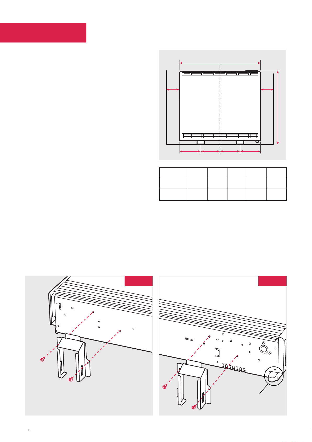
1. Place the heater within its packaging
flat on the ground with arrows printed
on the base of the carton pointing
upwards.
2. Feet are fitted in the default position
(X position) and can be moved to
the outside position (Y position) if
necessary. (Fig. 1a and Fig. 1b). NB:
Repositioning of feet may be required
depending on floor arrangement (e.g.
replacing an installation).
Stand the heater on its feet before
removing the packaging.
CAUTION SHOULD BE TAKEN NOT TO
REST THE HEATER UPON THE ROOM
TEMPERATURE SENSOR HOUSING. (Fig. 1b)
Dispose of packaging in an appropriate way.
Read these instructions carefully before
proceeding any further with the installation.
W
150mm
(min)
BA
Models 050 070 100 125 150
Feet Position
1 ‘A/B’
Feet Position
2 ‘A/B’
167/124 167/185 167/246 160/314 160/375
93/198 93/259 93/320 100/374 100/435
B
150mm
(min)
A
749mm
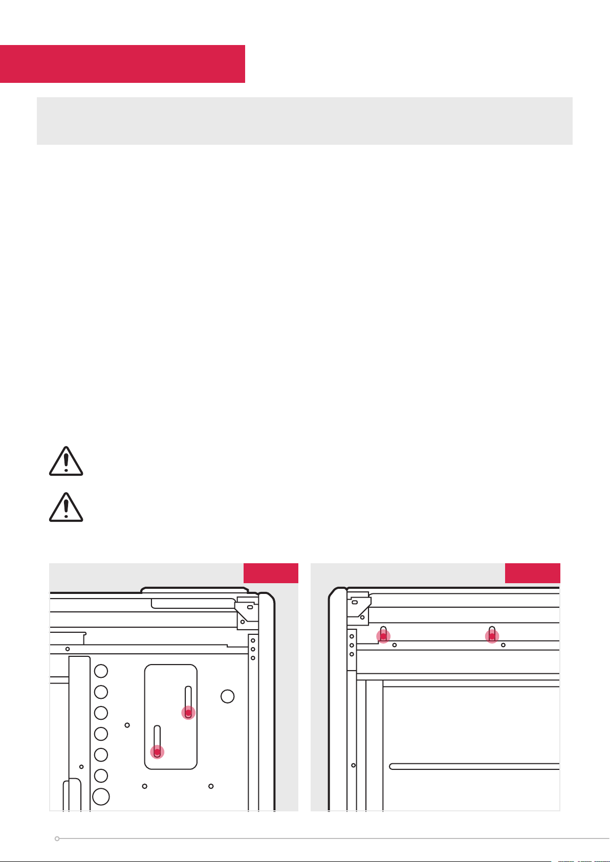
3. Ensure the heater is stable before removing the screws which hold the bottom grille
panel in position. (Fig. 2) Set the bottom grille to one side, avoiding its sharp edges
when handling.
4. Remove the two screws securing the front panel, located at the bottom of the heater
(Fig. 3). Once removed set carefully to one side to avoid damage.
NOTE - Retain these screws for reassembly. If misplaced, M4 x 10 Tritap screws must be
used. IMPORTANT - Do not use the outer top panel or the rear heat shield to lift or carry
the heater.
Fig. 1bFig. 1a
Y
X
X
Y
Room Sensor
Housing
6
Page 7
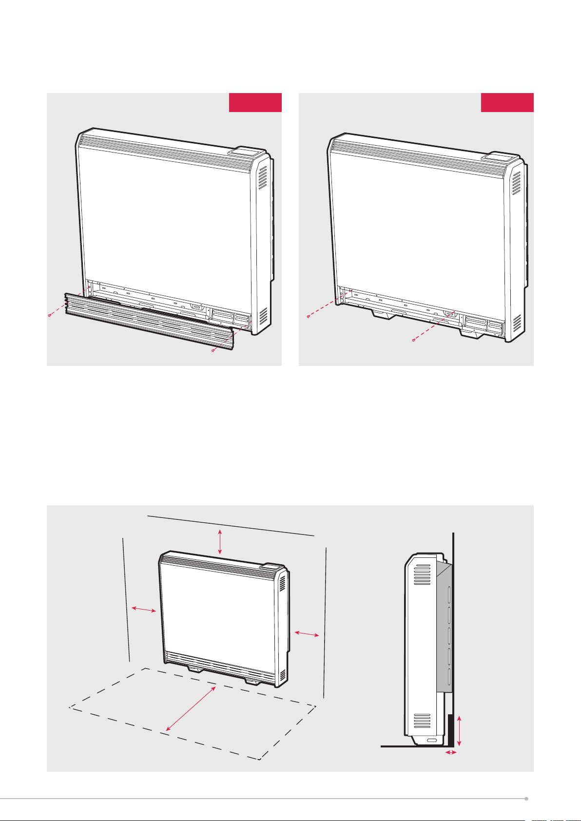
Fig. 2 Fig. 3
Ensure the back of the heater is flush against the wall. If the skirting board is
taller than 120mm and deeper than 15mm it should be cut to accommodate safe
installation of the heater.
Do not place objects within 300mm of the front of the heater
and 150mm (min. 75mm) either side.
250 mm
150 mm
150 mm
300 mm
120 mm
15 mm
7
Page 8
Installing the Heater
IMPORTANT Head of wall fixing screw must be flanged pan head type and have a
diameter no less than 11mm. No countersunk headed screws to be used for wall fixing.
The heater must be securely fixed to a wall. Screws with suitable wall fixings for solid
walls are provided. If other wall types are encountered it is the installer who must
choose the most suitable fixing.
SUGGESTED FIXINGS
SOLID BRICK/BLOCK: No. 10 size high temperature resistant plastic inserts, 8mm drill
bit. Drill hole 15mm deeper than plastic insert length.
PLASTERBOARD - If possible locate studding and use No. 10 woodscrews directly
into the wood, otherwise M5 rawlplug intersets are suitable.
NOTE: FOR OTHER WALL TYPES (eg. timber frame and hollow concrete) SEEK
SPECIALIST ADVICE.
If the floor is carpeted then the carpet should be slit and underlay cut away to allow
the feet to rest firmly on the floor. Carpet gripper must be locally removed so that the
feet may rest in a level position.
This appliance is heavy. The floor must be checked to ensure that it is capable of
bearing the weight of the unit, up to 165kg.
This Heater is rated IPX4
DO NOT UNDER ANY CIRCUMSTANCES ATTEMPT TO MOVE OR REPOSITION
THIS HEATER WITHOUT SEEKING EXPERT ADVICE. THE HEATER SHOULD
NEVER BE FREED FROM THE WALL WITH ENERGY CELLS INSIDE.
USE CAUTION WHEN INSTALLING THIS PRODUCT, UNPAINTED METALWORK
CAN HAVE SHARP EDGES.
Fig. 4 Fig. 5
8
Page 9
NOTE: ANY FIXING DROPPED INTO HEATER MUST BE RETRIEVED AS THEY MAY
IMPACT PRODUCT SAFETY OPERATION.
5. Place the heater in its final position and mark the fixing holes through the location
holes visible through the back of the heater.
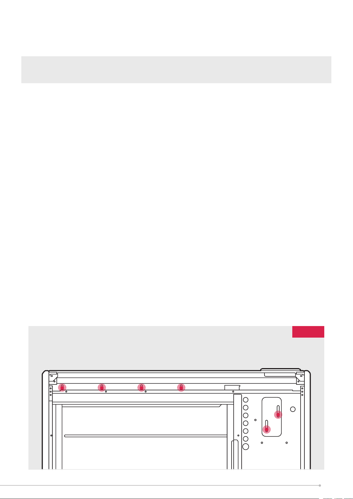
6. Six fixing positions must be selected for models XLE100, XLE125, XLE150 and at
least 4 fixing positions for models XLE050 and XLE070. Fig. 6.
Common fixing points for all heater sizes are shown in both Fig. 4 and Fig. 5.
Mark the positions for the fixing holes towards the bottom of each slot, this allows the
heater to settle once the energy cells have been fitted.
Move the heater away from the wall, drill the holes and fit the wall fixings best suited
to the application.
Secure the heater to the wall using correct quantity of screws required per model,
using the appropriate screw fittings.
NB: Do not fully tighten screws until energy cells are fully loaded to ensure full
weight is on feet and not on the wall fixings.
NOTE: UNDER NO CIRCUMSTANCES SHOULD ANY SCREWS BE REMOVED
WITHOUT FIRST REMOVING ALL ENERGY CELLS FROM THE HEATER.
NEVER FREE THE HEATER FROM THE WALL WITH ENERGY CELLS REMAINING
INSIDE THE HEATER CAVITY.
Fig. 6
9
Page 10
Electrical Connections
Warning: Before obtaining access to terminals, all supply circuits must
be disconnected.
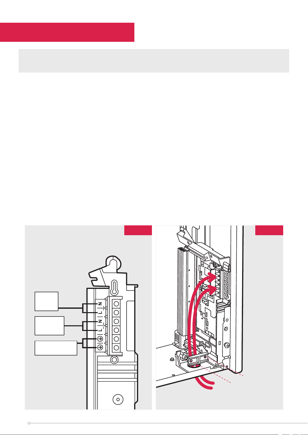
7. The heater leaves the factory configured to operate with two mains supplies, a 24
hour peak supply and an o peak switched supply. (Fig. 7)
Not suitable for use on single supply.
Storage / Fan circuit
Fan Circuit = PEAK L
Storage Circuit = OFF-PEAK L
Fan Circuit = PEAK N
Storage Circuit = OFF-PEAK N
The earth wire should be connected into the earth terminal block marked E
WARNING: Terminal block maximum torque 0.5 Nm
Fig. 7 Fig. 8
Switched Supply
Terminal Block
Neutral
Live
(Peak)
10
Neutral
Live
(O-Peak)
Earth
(Both Supplies)
Tighten Screws
Mains
Cable
Page 11

8. The mains cable entry and terminal block will be visible on the right hand side
of the unit. Insert the mains cables through the cable gland at the bottom of the
heater in readiness for connection (Fig. 8).
IMPORTANT: Only heat resistant ordinary polyvinyl chloride sheathed flexible cord
should be used, the following codes apply;
IEC: 60227 IEC57 or CENELEC: H05V2V2-F
Maximum Cable Sizes
Peak mains cable 1.5mm²
O-peak mains cable 2.5mm²
WARNING: Maximum torque 0.5 Nm
WARNING: All electrical connections to the terminal block must be secure to prevent
risk of ignition.
11
Page 12
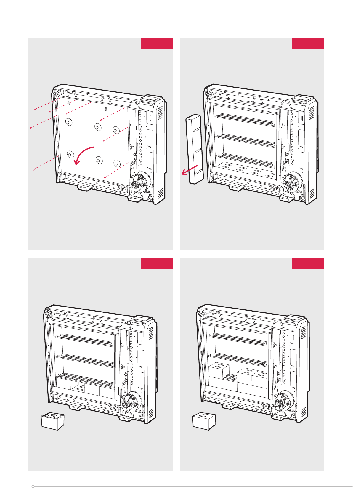
Fig. 9
Fig. 10
Fig. 11
Fig. 12
12
Page 13
Building the Heater Core
9. Remove the inner front and insulation to gain access to the core of the heater.
Lay the inner front carefully to one side to ensure it is not damaged. (Fig. 9)
10. Remove the cardboard element support and dispose of. (Fig. 10)
Energy Cells
The energy cells are supplied separately to the heater in packs of three.
The reference number is 047243.
Energy Cells should be handled with care due to the weight and risk of
hand/foot injury.
11. The energy cells have several grooves on one surface for locating around
the elements. The two slots through the centre of the energy cell create the
air passages within the core.
Position the first energy cell of the bottom row to the right, firmly pressed against the
side insulation with the element grooves facing upwards and fitting neatly around the
element. Angle the element upward to fit the energy cell.
Position the second energy cell in the row against the left-hand insulation. Place the
remaining energy cells between the first and second in the row. (Fig. 11)
DO NOT DISCONNECT THE ELEMENT TERMINALS
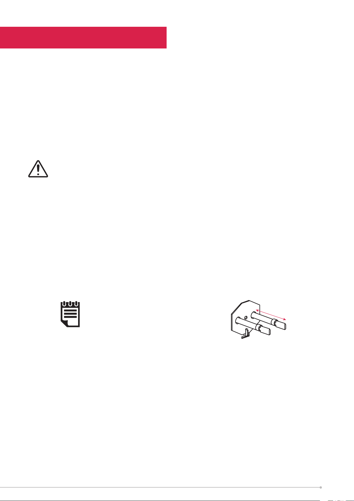
In addition ensure the slots for the air passages line up with the holes in the
base insulation.
NOTE:
The element tails must extend no
further than 30mm into the right
hand chamber.
Fit the remaining energy cells to the bottom row, being careful not to damage or
dislodge the element.
30mm ±1mm
Note - The bends in the element locate around the grooves in the energy cell to
secure the element.
12. Position the second row of energy cells on top of the first but this time the energy
cells must be upside down ensuring the grooves are positioned over the elements.
(Fig. 12)
13
Page 14
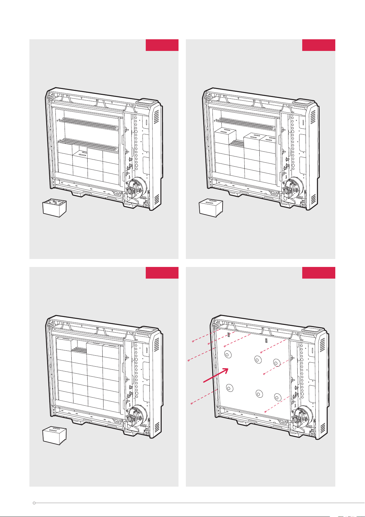
Fig. 13
Fig. 14
Fig. 15
Fig. 16
U
14
Page 15
13. The third row of energy cells is positioned in a manner similar to the first row. Again
be careful not to damage or dislodge the element. (Fig. 13)
14. Fit the fourth row of energy cells above the third row in the upside position. Again,
the first energy cell should be positioned firmly against the right-hand insulation, and
the second energy cell should be positioned firmly against the left-hand insulation.
(Fig. 14). Repeat for the fifth and sixth rows of energy cells built around the third
element to complete the core build.
15. Remember the top row of energy cells must be fitted upside down. (Fig. 15)
Check that all the energy cells are secure and evenly located.
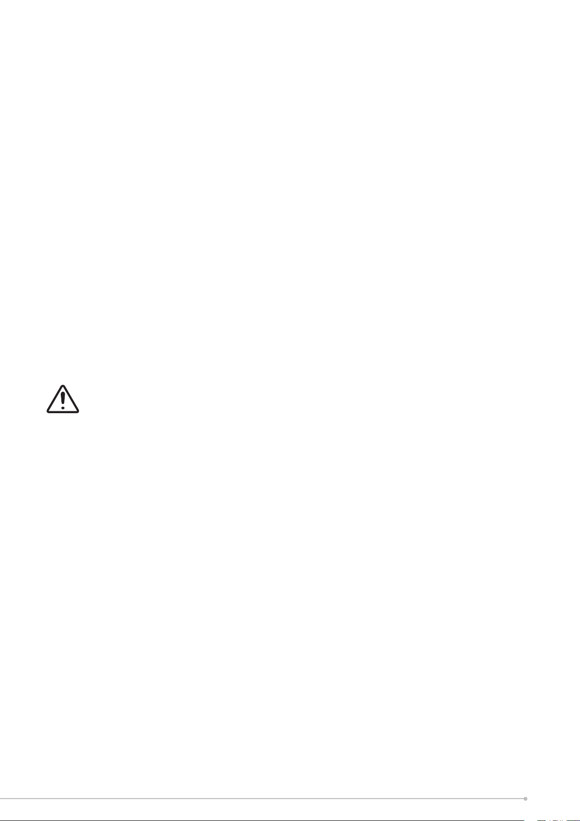
16. Close the core by refitting the inner front panel complete with insulation, starting at
position ‘U’ and working clockwise. (Fig. 16)
Ensure the bottom tabs are located inside the chassis and that the screws are tightly
secured down each edge.
Ensure the screws retaining the heater to the wall are fully tightened, once the energy
retention cells are fully loaded. (Fig. 6)
IMPORTANT
Double check all mains connections are secure and excess cable is restrained
and not in contact with any of the heater casing.
ON NO ACCOUNT SHOULD ANY SURPLUS CABLE BE PUSHED INSIDE OR BEHIND
THE HEATER.
Once installed DO NOT attempt to reposition the heater without first unloading the
energy cells.
Reassembly
To replace the bottom grille and front panel, reverse steps 3 and 4 of these instructions
under the section headed Preparation.
Inspect the grille guard for damage before refitting the lower grille to the heater.
Ensure all fixings are secure.
15
Page 16
Operation
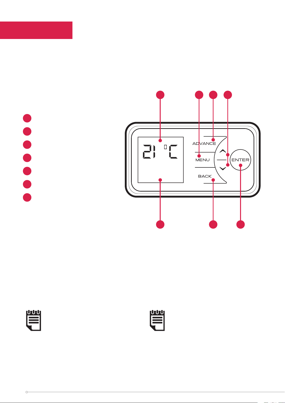
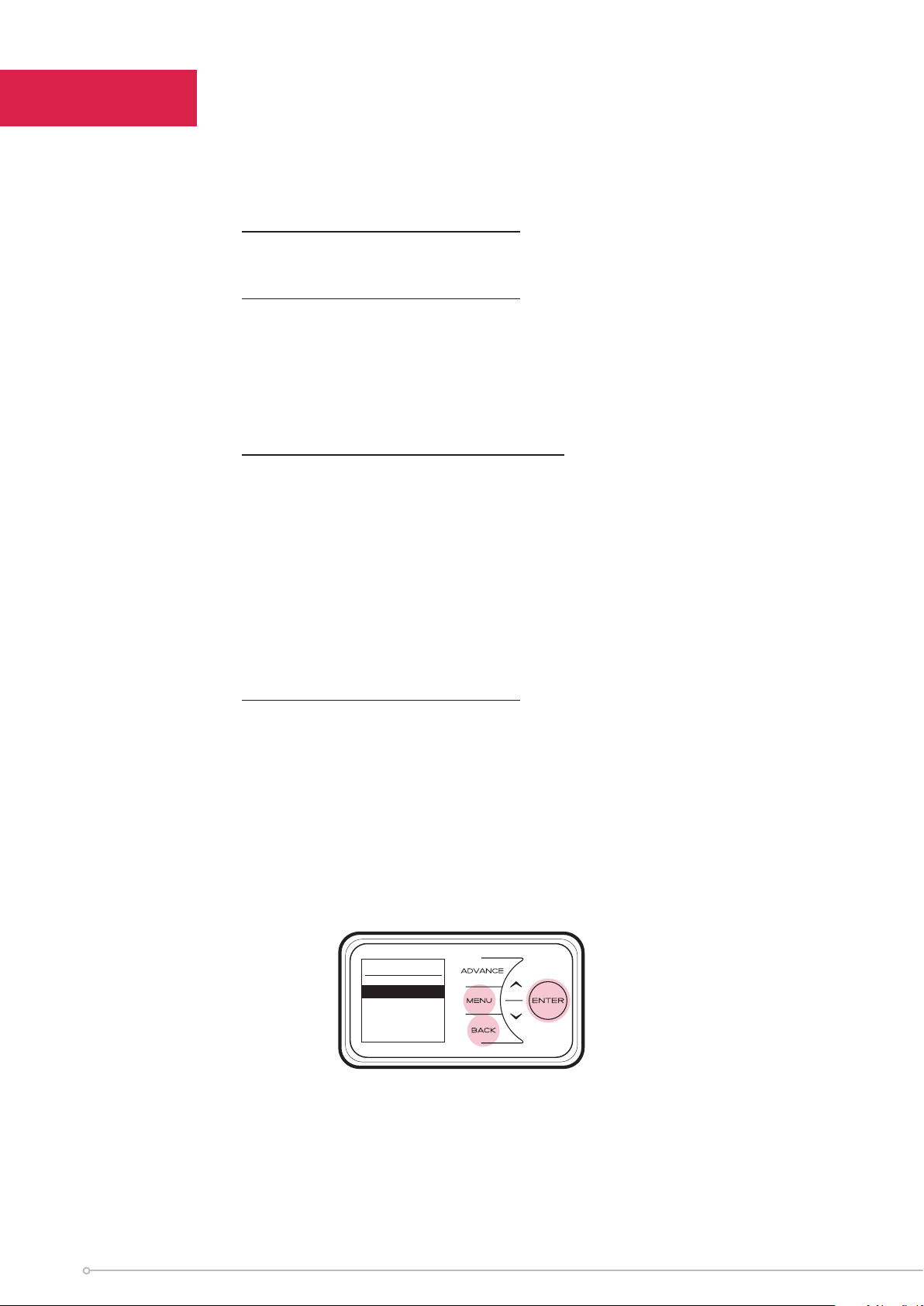
The controls are located on the top of the heater. The heater is fitted with an adjustable
electronic controller consisting of a display screen and six touch sensitive buttons.
1
Display Screen
2
‘Menu’ Button
3
‘Back’ Button
4
‘Up and Down’ Arrows
5
‘Enter’ Button
6
‘Advance’ Button
7
Heating Status
1
Out All Day
Comfort On
2 46
57 3
The heater is fitted with an adjustable thermostat enabling the room temperature to
be controlled. The minimum room temperature is 7°C. The maximum temperature is
set to 26°C. A temperature of 21°C represents a normal room temperature.
NOTE:
Your heater may produce some noise
during operation. This noise is caused
by the low noise fan and expansion
and contraction of the metalwork as it
changes temperature, and is normal for
this type of product. Whilst the noise
produced is usually very quiet, certain
environmental factors can make it more
noticeable, such as hard flooring or
minimal furnishings.
16
NOTE:
Should the heater fail to operate, this
may be due to the room temperature
being higher than the thermostat
setting.
Page 17

Control Functions
The heater controls can be easily adjusted by using the six buttons on the User Interface.
The Display Screen shows the options available at each stage of adjustment.
1
Menu - displays the main options list;
2
- Date/Time - Set the date and time.
- Mode - Set the mode of operation.
- Options - Keypad sound, daylight savings time, communication settings and service
information.
Back returns to the previous programming stage.
3
The UP and DOWN buttons are used to navigate through the menus and alter
4
setting values. The UP and DOWN buttons are also used to adjust the required
room temperature on the main screen. The screen colour changes based on the
temperature selected, showing deep blue through to bright red.
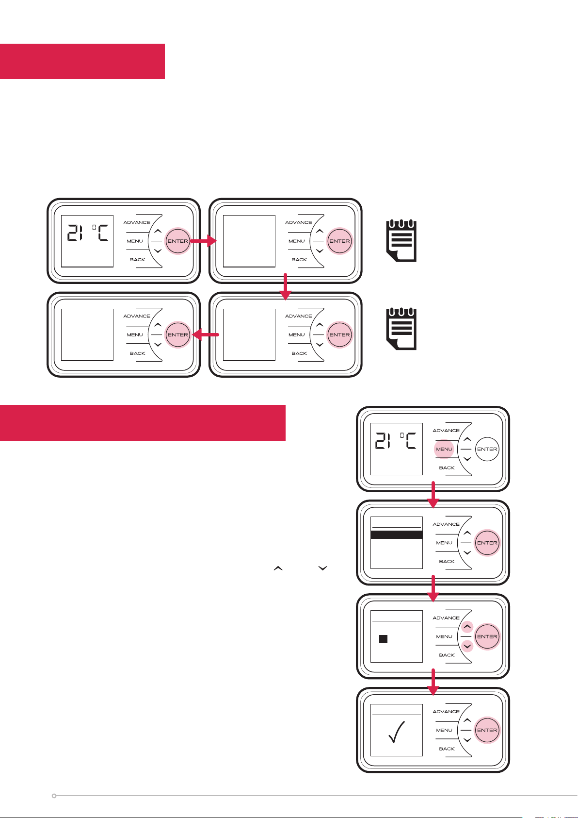
Enter is used within the menu options to confirm settings. On the main screen
5
pressing Enter will display the enabled features.
The timed periods during which the heater is providing heat are defined as ‘Comfort
On’ (this is displayed at the bottom of the screen).
Outside of heating periods the heater will not deliver heat and these periods are
called ‘Comfort O’.
While constant heat modes are active, the mode of operation is displayed at the
bottom of the screen e.g. ‘Out All Day’.
The Advance button overrides the heating settings and changes the operational
6
state of the heater. Pressing Advance will cause the heater to remain on until the
next Comfort O period is due, or o until the next Comfort On period is due.
17
Page 18
Main Screen
After 30 seconds the heater will default back to the Main Screen. Here the chosen
temperature is displayed along with the mode of operation. Any use of the Advance,
Boost, Setback function will be displayed here, and pressing Enter will show engineer’s
diagnostics and 7 day history screens.
When left inactive for a long period of time this display will ‘sleep’ and the text will
disappear. Press any button for its return.
U1:033 CC:016
AL6027
Out All Day
Comfort On
7 Day History
Energy Used
kWh
20/10/2017 0.0
21/10/2017 0.0
22/10/2017 0.0
23/10/2017 0.0
24/10/2017 0.0
25/10/2017 0.0
(0X422)
Out All Day
A 2 3300 0
B 422 M 0
C 19.3 16.1
D 6.5 R 12667
E 21.0 26.0
F 19.3 15.9
G 28840 0 0
H 135 0 1841
Setting the Date and Time
The heater incorporates a real time clock with
calendar function. The time clock has a battery
backup that will keep the clock running in the
event of a mains power outage.
Out All Day
Comfort On
NOTE:
The display screen
will return to the main
screen after a period of
30 seconds of inactivity.
NOTE:
Pressing enter will show
the engineer’s diagnostics
and 7 day history screens.
Ref: page 17.
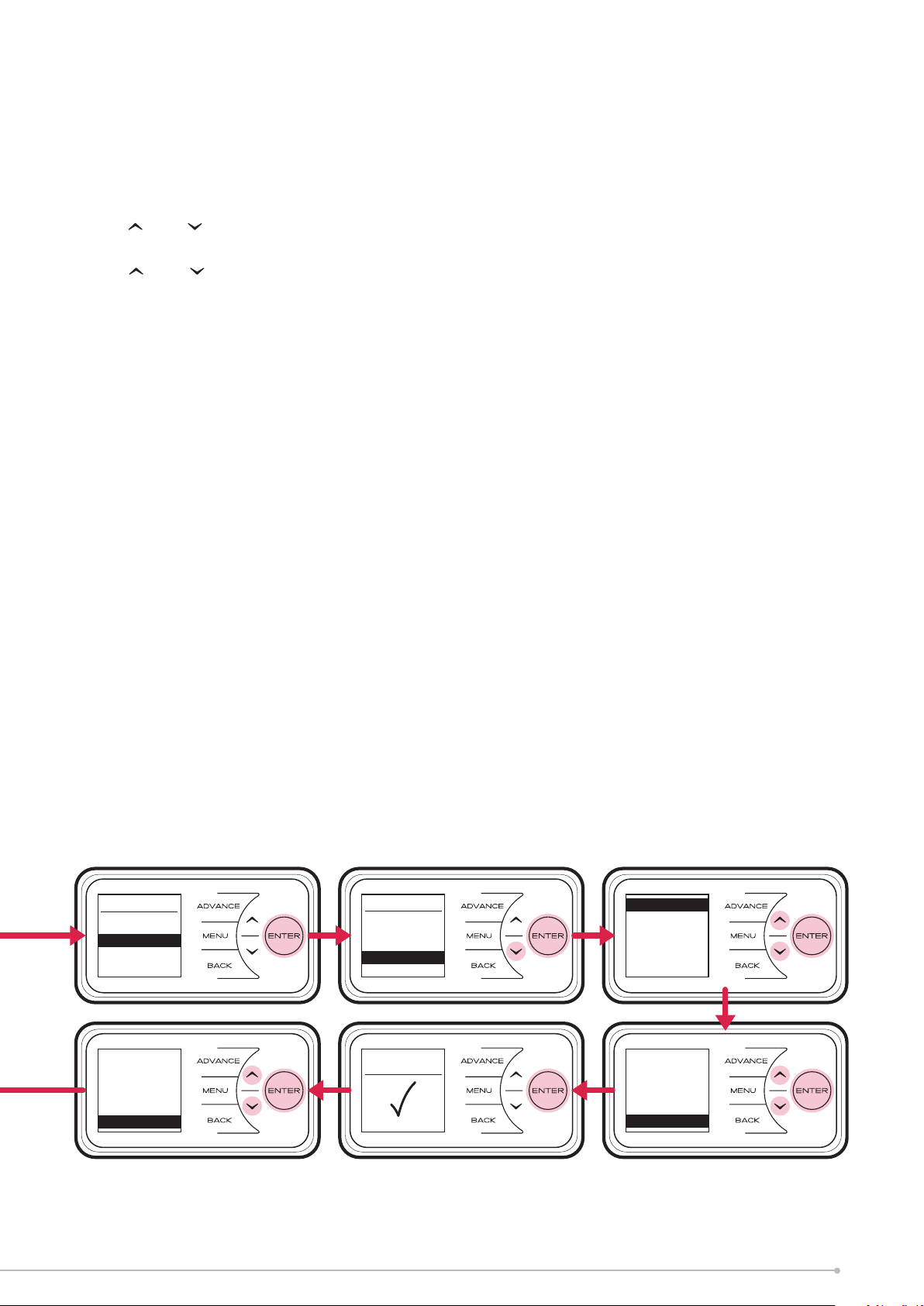
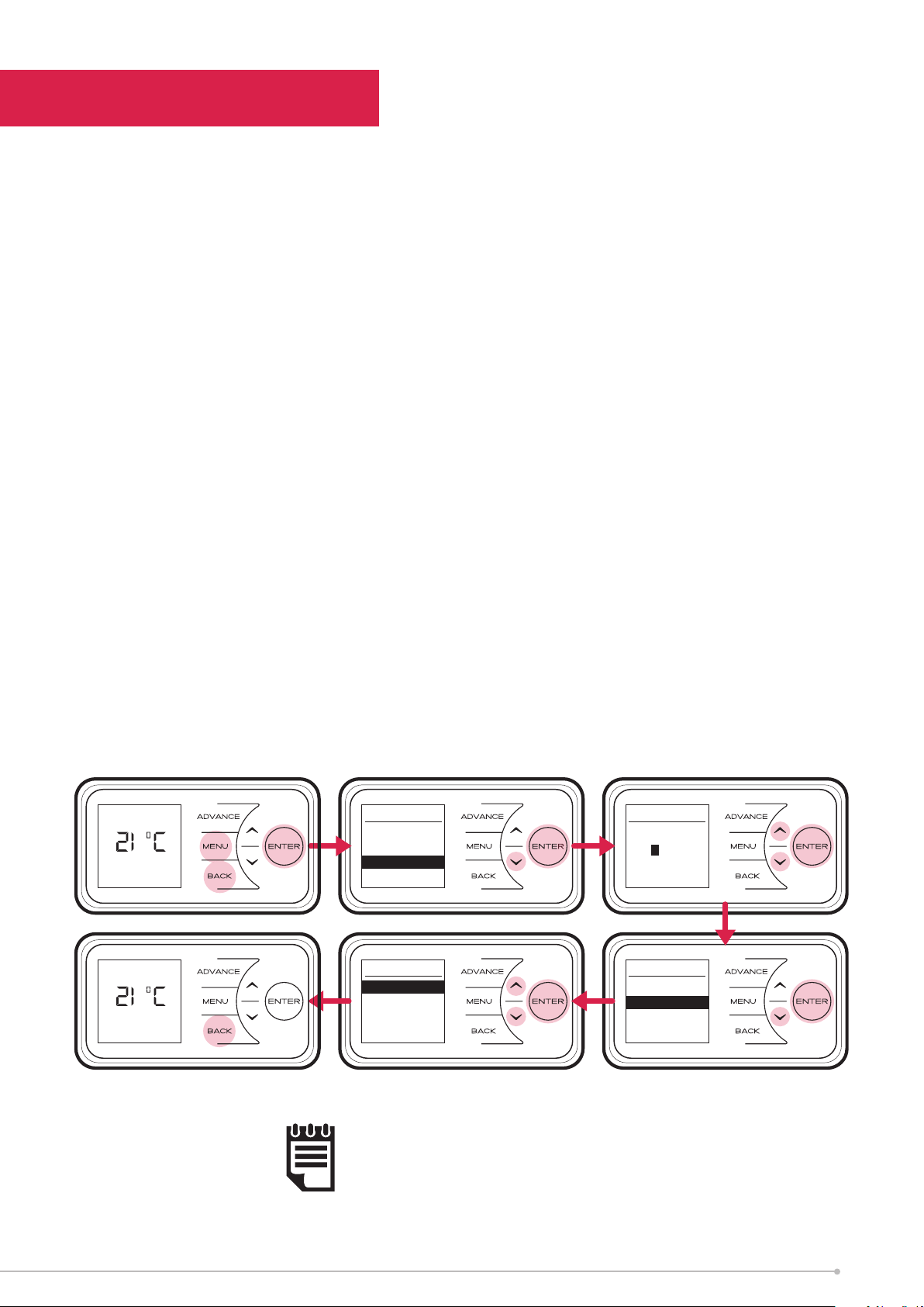
To adjust the time or date follow the steps below.
Press the Menu button. Select Date/Time
by pressing the Enter button. Press and
to select the correct day of the month and press
Enter to select.
Repeat this operation, until the date and time has
been set, ensuring to press Enter to select. Press
Back button to return to the Main Screen once
Set has been displayed.
18
Main Menu
Date/Time
Mode
Options
Date/Time
THU
27/07/2017
07:12
Date/Time
Set
Page 19
Modes of Operation
The heater comes pre-programmed with a set of heating profiles. There are three
options available - two pre-programmed and one user adjustable timer;
1. User Timer (pre-programmed, factory default) - provides greatest flexibility
to the user. Four time slots are available throughout the day and these can be
customised for each day of the week. Factory default times: 06.30 until 09.30,
11.00 until 13.00, 15.00 until 17.00, 18.00 until 22.00.
2. Out All Day (pre-programmed) - has the following preset times Monday to
Sunday, which can be altered if desired 07.00 until 08.30 17.30 until 22.00,
(factory default times).
3. Holiday - set the date of return and the temperature required. 7°C is advised
if you just want to protect the property from frost while you are away.
The heater can also maintain a constant room temperature using the following
modes;
1. Boost mode heats the room to a selected temperature for 1, 2 or 3 hours.
2. Auto Boost Function maintains a room temperature during comfort periods,
when the core is depleted.
3. Setback mode maintains a room temperature outside comfort periods. This
mode should be used to provide protection against frost or where big drops in
temperature are unwanted.
NOTE:
In all modes, except holiday mode, and can be used to
adjust the required room temperature.
NOTE:
It is recommended that the timer is used as doing so can
reduce the running cost. Operating the appliance in the
permanent heating modes as Boost, Auto Boost or Setback
may result in increased running costs.
19
Page 20
Choosing and Setting a Mode
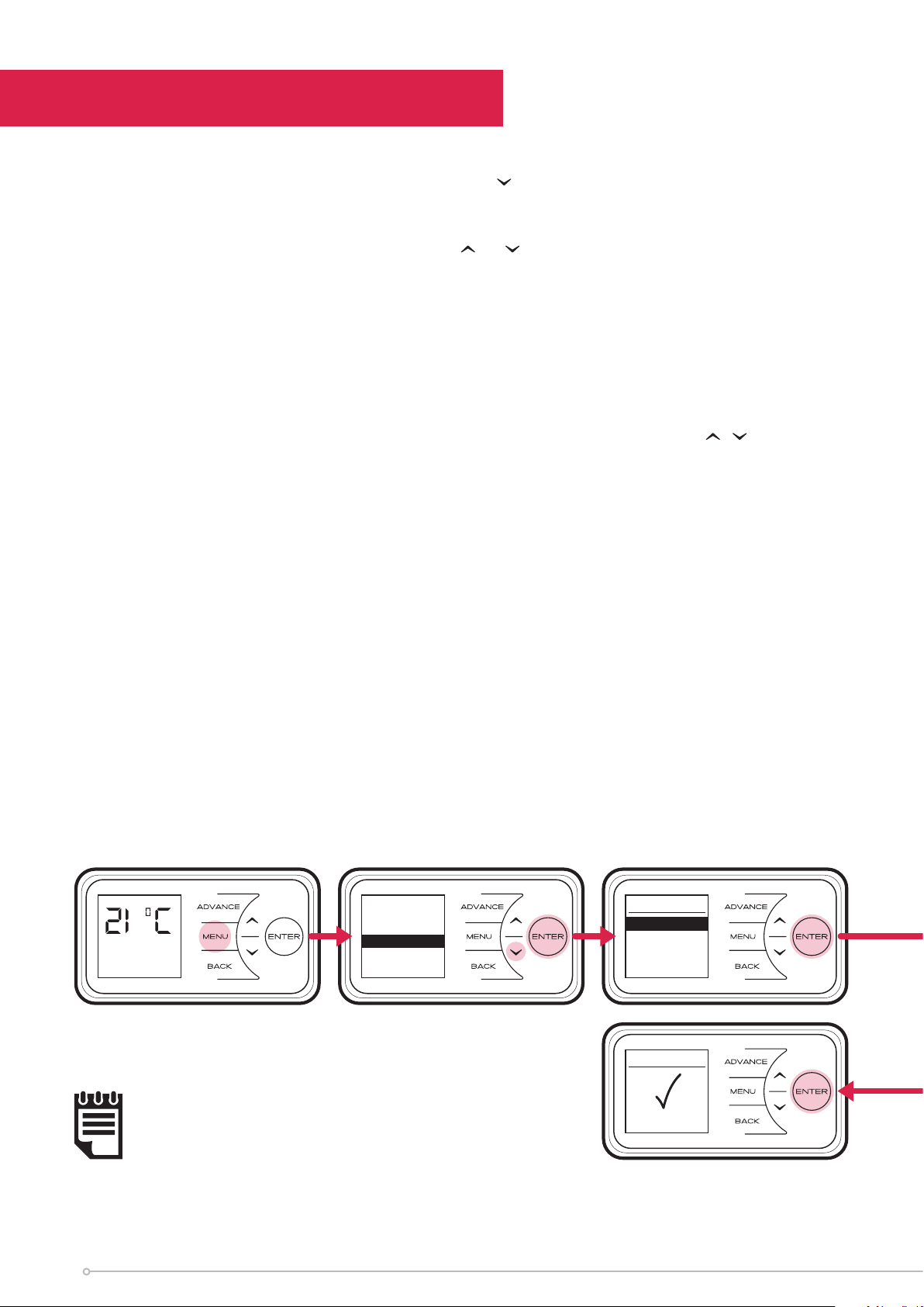
Timer Modes
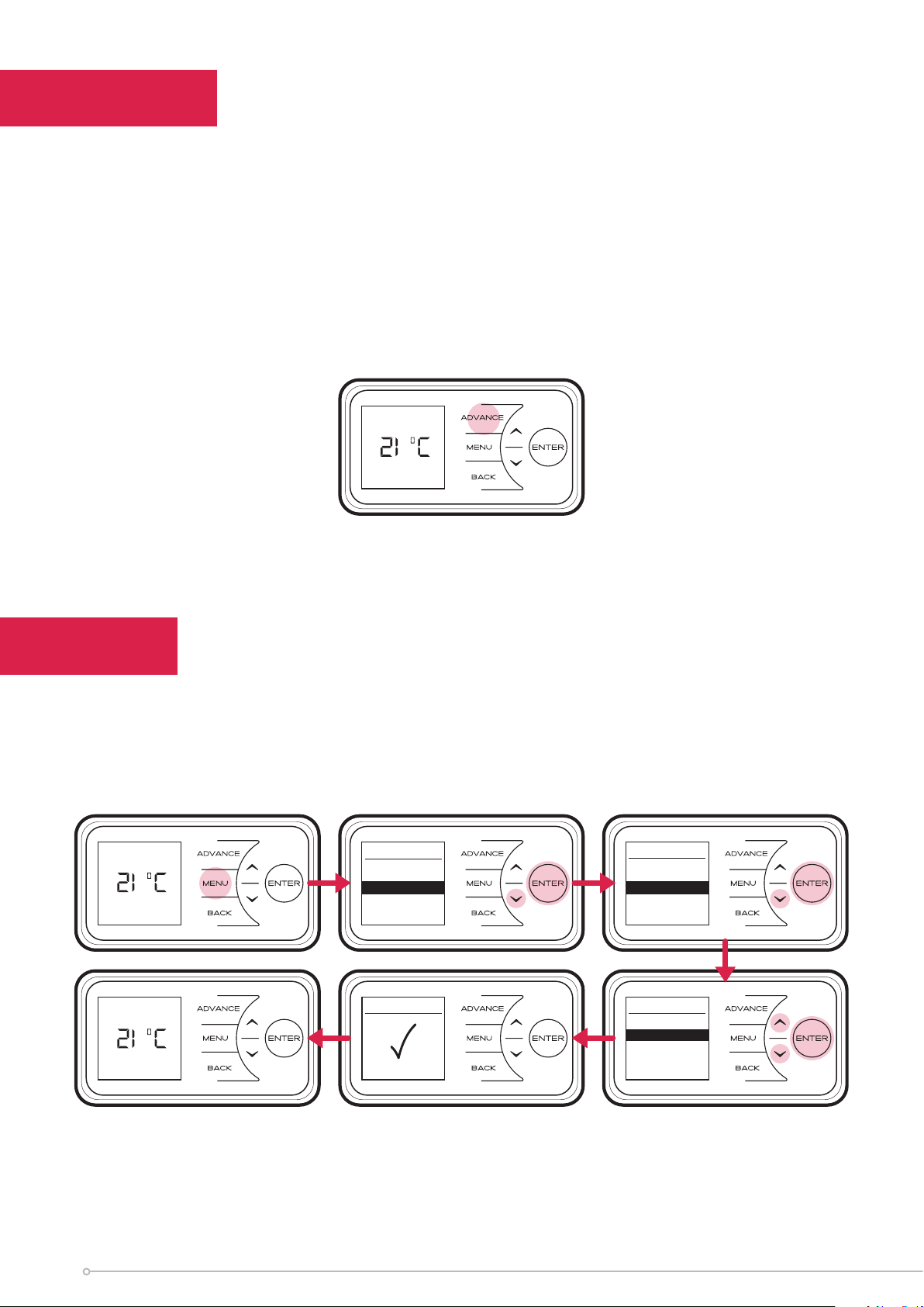
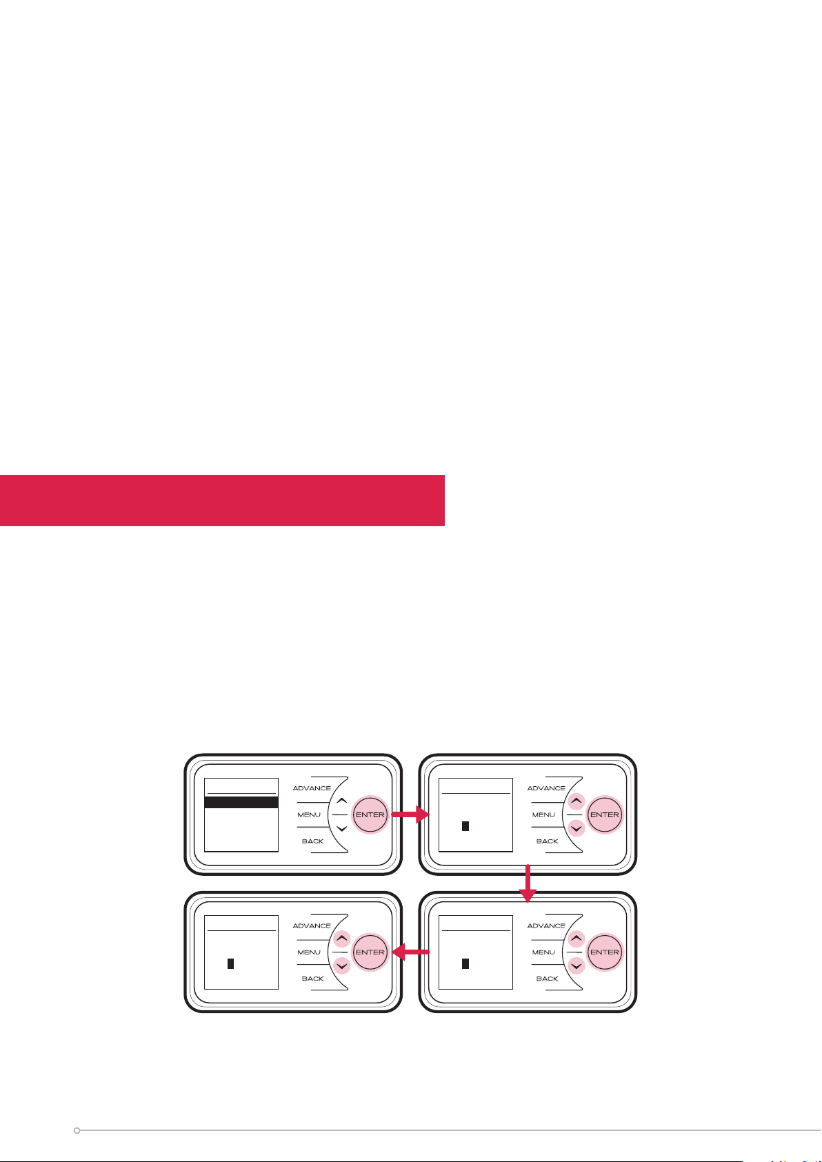
To choose a timer mode press Menu and then to select Mode. Then press Enter.
Then select Timer Mode, again using the Enter button.
Select the mode required, by pressing the or followed by Enter.
For options Out All Day, and User Timer, three choices are available - Select, Preview
and Modify.
• Select - choose this timer option.
• Preview - view the times currently set.
• Modify - change the times currently set.
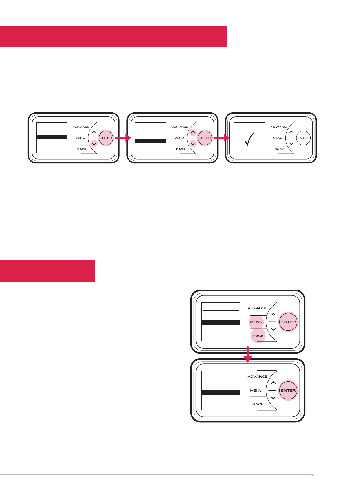
When Modify is chosen, select and change each option using the , and Enter
buttons. At the end of each period, select Next to move to the following period. When
a day is complete select Save to update it.
Once the first day has been set up it is possible to copy these settings to successive
days or all days by either choosing Copy Next or Copy All.
If preferred each day can be modified individually and saved. It is also possible to
Clear each day or Clear All days to factory default times. Options are;
• Save - save times for one day.
• Copy Next - copy times to following day.
• Copy All - copy times to all seven days.
• Clear - factory defaults all times that day.
• Clear All - factory default times for all seven days.
To select a mode, choose Select and press Enter.
Main Menu
Date/Time
Mode
Out All Day
Comfort On
Options
Mode
Timer
Boost
Setback
Copy All
20
NOTE:
Once modified a programme
must be selected if you want
to begin using it.
Selected
Page 21
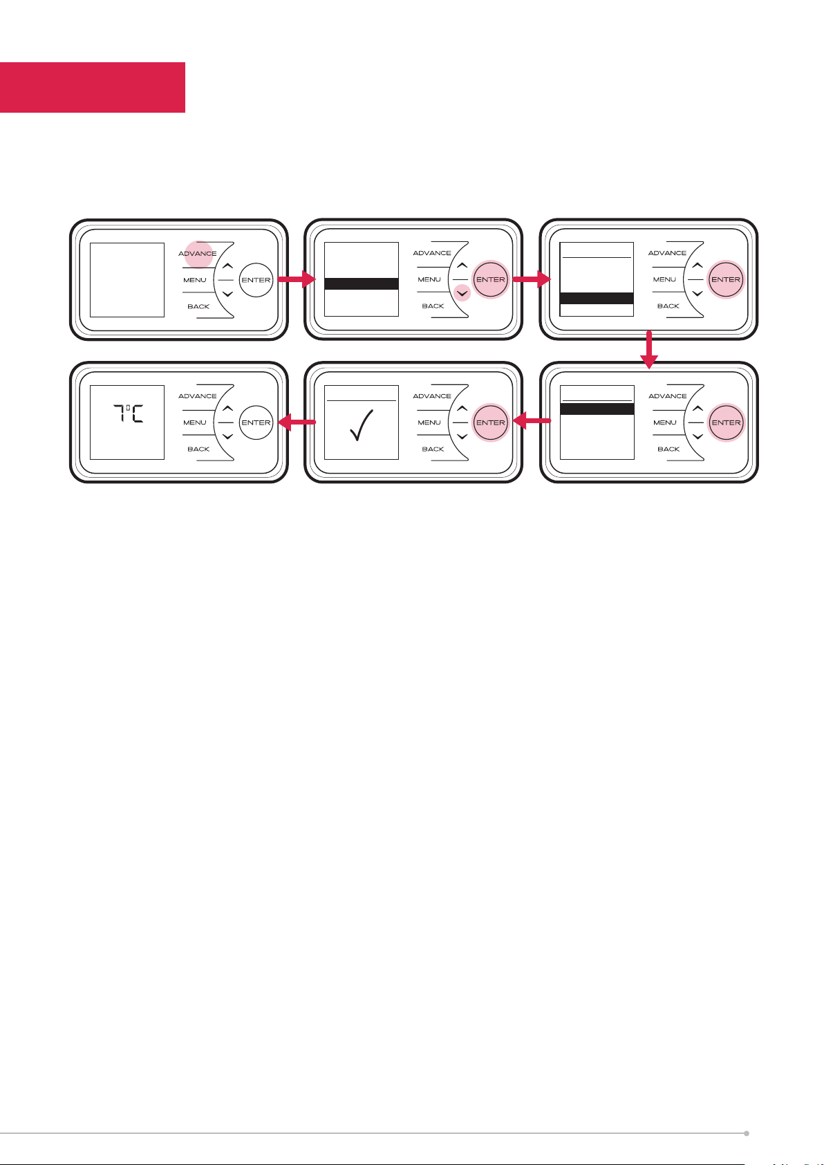
In Holiday mode the date until the room will be unoccupied can be set/adjusted together
with the required room temperature.
Press and to set the return date, then press the Enter button.
Press and to choose a temperature to be maintained during this period and press
the Enter button. At the end of the holiday mode the heater will automatically revert
back to the previously selected programme.
Timer Mode
User Timer
Out All Day
Holiday
< THU >
< Evening >
ON: 17:00
OFF: 22:00
Copy All
Out All Day
Select
Preview
Modify
Out All Day
THU
Saved
< THU >
< Morning >
ON: 07:00
OFF: 08:30
Next
< THU >
< Evening >
ON: 17:00
OFF: 22:00
Save
21
Page 22
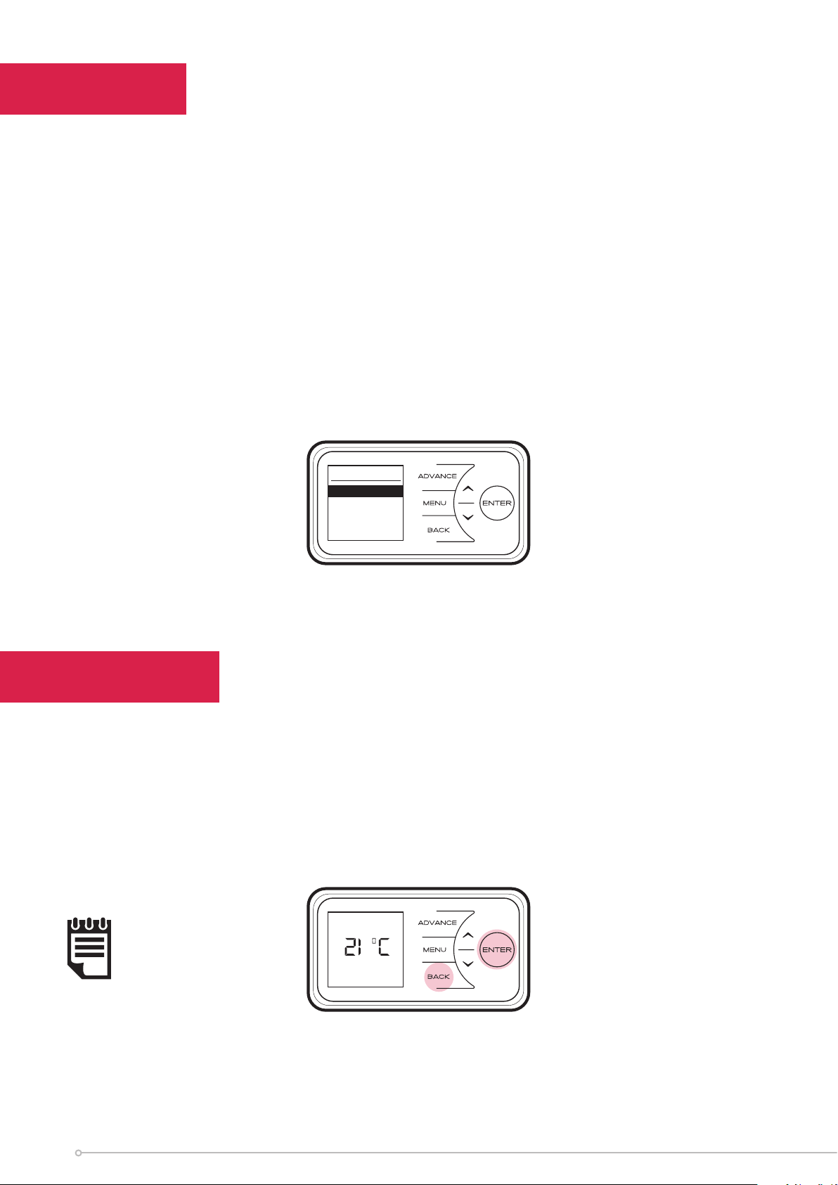
Advance
The Advance function allows the heating profile of the heater to be changed
temporarily. When a timer has been selected, the Advance function is used to begin
the next Comfort On mode early. If the heater is in Comfort O mode and heat is
required, press the Advance button.
If the heater is in Comfort On and heat is not required, press the Advance button and
the heater will turn o until the beginning of the next Comfort On period.
Advance
Comfort Off
Boost
Boost mode provides temporary heating for one, two or three hours. Auto Boost
maintains a room temperature during Comfort On periods, when the core is depleted.
Mode
Timer
Boost
Setback
Out All Day
Comfort On
Main Menu
Date/Time
Mode
Options
22
Boost 1hr
Out All Day
Comfort On
1 hour boost
Selected
Boost Menu
No Boost
1 hour
2 hour
3 hour
Autoboost
Settings
Page 23
Setback
Setback mode maintains room temperature outside comfort periods. This mode should
be used to provide protection against frost or where big drops of room temperature
are unwanted.
Mode
Timer
Boost
Setback
Setback
Disable
Enable
Setback Temp
Settings
00:11
Comfort Off
Next on at
06:30
SETBACK
Next on at
06:30
Main Menu
Date/Time
Mode
Options
Setback
Selected
Please Note This may deplete the storage core faster than a timer operation alone.
Low core temperate will cause the product to use peak energy in order to achieve the
desired room temperature if Auto Boost is enabled (Page 22).
23
Page 24
Options
The Options menu allows the settings to be modified to suit the user’s preferences.
These are;
DST Rule - Select your daylight saving setting. The heater clock will automatically
adjust for daylight saving (British Summer Time as it is often referred to).
If no adjustment is required then select none.
Report - Service information is displayed.
Sound - Audio feedback can be enabled or disabled.
Comms - Choose to enable or disable Wireless Connectivity. If additional RF Module
is connected, user will have option to enable or disable RF communications.
Options
DST Rule
Report
Sound
Comms
Child Lock
In cases where unauthorised persons may tamper with the control settings it is possible
to set a tamper-proof feature.
To lock the controls press Back and Enter for three seconds. Child Lock will appear
at the bottom of the screen. To unlock the control repeat the action of pressing Back
and Enter for three seconds.
24
NOTE:
The controls cannot
be adjusted when
child lock is active.
Out All Day
Comfort On
Child Lock
Page 25

User Information
Press and hold Enter for five seconds to enter the User Information menu;
Open Window detection (OW), when enabled, the heater will reduce the target room
temperature to limit the energy waste when an open window is detected. Disabled as
default.
Factory Reset returns all settings to the factory presets.
Extra Charge - forces an extra charge of up to seven hours during o-peak periods.
If the output of the heater is not able to deliver the required comfort level then it is
possible to force the heater to store additional energy. In this way more electrical
energy is stored during the o-peak period and this will increase comfort levels.
Up to seven hours additional o-peak charging can be selected.
NOTE:
The extra charge option will lead to more energy being stored during
the o peak period, this will lead to higher running costs. Only use this
setting when a room is consistently below the required temperature
and yo are sure that the timer mode is set up and selected correctly.
User Info
Open Window
Factory
Extra Charge
25
Page 26
Service
In order to enter the Service menu, Back, Menu & Enter must be pressed simultaneously
and held for 10 seconds.
Charge Time - for Service personnel use only.
Slave Mode - for Service personnel use only.
If more than one heater is installed in the same room it is
recommended that the smallest capacity heater is set as a Slave.
Disabled as factory default.
Landlord Lock - for User and Service personnel use.
Allows to lock:
- the ability to select or adjust the Timer Mode
- Use of Boost and Setback functions
- Limit maximum operating temperature
Disabled as factory default.
Default code : 0 0 0 0
Rm Temp Oset - for Service personnel use only.
Allows to set a Room Sensor temperature oset.
Factory pre-set oset as default.
26
Service
Change Time
Slave Mode
Landlord Lock
Rm Temp Offset
Page 27
Landlord Lock Mode
Introduction
This appliance has a built in Landlord lock mode, when this mode is activated all
functionality of the Boost and Setback is locked and the user will have no ability
to select or adjust timer mode. It is possible to limit the maximum operating
temperature in the Landlord mode.
Operation in Landlord Lock Mode
When Landlord Lock mode is active the specific appliance modes are locked, it is not
possible for the user to adjust predetermined comfort periods. During these periods
the appliance will control the room to a desired temperature. The set point can be
adjusted by the user however it is possible to assign a maximum set point limit during
the Landlord Lock mode setup. Once the Landlord Lock mode is disabled, the use
of Boost and Setback modes and selection/adjustment of timer mode are enabled.
To activate Landlord Lock mode the user must enter service menu first. Back, Menu &
Enter must be pressed simultaneously and held for 10 seconds. To access the Landlord
Lock menu the user will be prompted to enter the Landlord Lock PIN.
Enabling Landlord Lock Mode
After correct PIN entered, select Enable using Enter. Landlord Lock mode will be
enabled, normal functionality of the appliance will be disabled allowing only the
functionality determined by Landlord Lock.
Disabling Landlord Lock Mode
After correct PIN entered, select Disable and confirm using Enter. Landlord Lock will
be disabled and full appliance functionality will be enabled.
Landlord Lock
Enter Code
0 000
Out All Day
Comfort On
Service
Charge Time
Slave Mode
Landlord Lock
Rm Temp Offset
Out All Day
Comfort On
Landlord Lock
Change Code
Boost Lock
Setback Lock
Timer Mode
Lock
Max Temp
NOTE:
The default password is 0000,
the password can be changed from
within the Landlord Lock mode menu.
Landlord Lock
Disable
Enable
27
Page 28
Change Code - Allows to customise the Landlord Lock code
Default Code: 0 0 0 0
Boost - Allows to Enable or Disable the Boost function lock.
Enabled by default
Setback - Allows to Enable or Disable the Setback function lock.
Enabled by default.
Timer Mode - Allows Enable/Disable selection or adjustment of the Timer Mode.
Enabled by default.
Max Temp - Allows to limit a maximum operation temperature.
Set to 26°C by default.
Landlord Lock Mode Settings
Changing the Password
It is possible to set a user defined Landlord Lock PIN code. Once changed, the PIN
code will be required to access the Landlord Lock mode menus.
To change the PIN code select “Change Code” from the main Landlord Lock menu. To
complete the change, follow the on-screen instructions, it will be necessary to input
the current PIN and then set the new PIN code.
Landlord Lock
Change Code
Boost Lock
Setback Lock
Timer Mode
Lock
Max Temp
Change Code
Enter
Current Code
0 000
28
Change Code
Confirm
New Code
0 000
Change Code
Enter
New Code
0 000
Page 29
Boost, Setback and Timer Mode Lock
It is possible to activate Boost, Setback and Timer Mode lock, this ensures that when
the Landlord lock is enabled, normal functionality of the appliance will be disabled
allowing only the functionality determined by Landlord lock.
These locks can be enabled or disabled from within the Landlord lock settings menu.
Landlord Lock
Change Code
Boost Lock
Setback Lock
Timer Mode
Lock
Max Temp
Boost Lock
Disable
Enable
Settings Lock
Boost Lock
Enabled
Maximum Temperature
A maximum temperature limit for the room during Landlord lock mode can be
applied. This will restrict the users ability to increase the room temperature beyond
a set value. The maximum temperature can be set by selecting ‘Max Temp.’ in the
Landlord lock settings menu. The temperature can be adjusted using the arrow keys
and then confirmed using the Enter key.
Slave Mode
If more than one heater is installed in the
same room it is recommended that the
largest capacity heater is set as the master
and all smaller capacity products are set as
slaves.
Press Menu, Back and Enter for 3 seconds
to enter the service menu, select ‘Slave
Mode’ and press Enter. Select ‘Enable’.
Service Menu
Charge Time
Slave Mode
Landlord Lock
Rm Temp Offset
Slave Mode
Disable
Enable
29
Page 30

Energy Saving Tips
The energy we use to heat, light and power our homes contributes over a quarter of
the UK’s carbon emissions, the principle contributor to climate change. Around half the
energy used in the home is for heating and hot water, so using your heating system
eciently will not only help the environment, but also save you money.
Energy eciency tips for heating and hot water
1. Don’t set the temperature to high...
By reducing the thermostat setting by just 1°C can reduce your energy use by as
much as 10%. And if you’re going away during the winter, leave the thermostat on
the frost protection setting to provide protection from freezing at a minimum cost.
2. Use it where you need it...
Set the appropriate temperature on your heaters for the room they are in; for
example, leave the thermostat on a heater in a spare bedroom on a lower setting.
3. Use it when you need it...
Use heaters fitted with timers or linked to central controllers to turn the heating on
only when you need it and automatically switch it o when you don’t.
4. Curtains
Close your curtains at dusk to stop heat escaping through the windows.
5. Windows
Nearly 25% of heat loss can occur through poorly insulated frames and single glazing.
If you can’t aord to double glaze all your windows, go for the rooms you heat most.
6. Treat your hot water tank...
Give it a jacket An insulating jacket for hot water tanks costs only a few pounds and
pays for itself within months. Fit one that’s at least 75mm (3”) thick and you could
save £10-15 a year.
7. Water
Use a shower if you have one to save time, money and water. Don’t set the thermostat
too high on your water heater - 60°C/ 140°F is usually adequate for bathing and
washing. Put the plug in when running hot water in your sink - leaving hot taps
running is both wasteful and expensive. Ensuring dripping taps are repaired quickly.
In just one day, you could waste enough water to fill a bath.
Other Energy Saving Tips for Around the Home
1. Lights
Turn o lights whenever you leave a room for more than ten minutes. Use low-
energy bulbs wherever you can as they use less than a quarter of the electricity
used by ordinary light bulbs and last ten times longer!
2. Cooking
Use the right size pan for food and cooker hob. Keep saucepan lids on - this enables
you turn down the heat. Boil water for cooking in a kettle first.
30
Page 31

Important
During the initial operation, some odour may be noticed due to the newness of materials
used in manufacture. This is normal and will disappear after a short period of use. It is
however advisable to keep the room well ventilated.
Cleaning
WARNING - ALWAYS ISOLATE THE POWER SUPPLY BEFORE CLEANING THE HEATER.
Before commencing cleaning allow the heater to cool. The outside can be cleaned by
wiping it over with a soft damp cloth and then dried. Do not use abrasive cleaning
powders or furniture polish, as this can damage the surface finish.
Discolouration of wall finishes can sometimes occur immediately above a heater
due to the properties of some paints and decorating materials or the presence
of environmental impurities in the air (such as soot, cigarette smoke or incense
generated from the burning of candles, etc.). A suitable shelf (available from Dimplex)
may be fitted to limit the extent of any wall discolouration.
Recycling
For electrical products sold within the European Community. At the end
of the electrical products useful life it should not be disposed of with
household waste. Please recycle where facilities exist. Check with a Local
Authority or retailer for recycling advice in your country. Batteries should
be disposed of or recycled in accordance with WEEE Directive 2012/19/
EU. Packaging should be recycled where possible.
31
Page 32

Warranty
What does a Dimplex Warranty cover?
Dimplex products deliver reliable service for normal, household use in domestic
settings. All Dimplex products are individually tested before leaving the factory.
If you are a consumer and you experience a problem with your Dimplex product, which
is found to be defective due to faulty materials or workmanship within the Warranty
Period, this Dimplex Warranty will cover repair or - at the discretion of Dimplex –
replacement with a functionally equivalent Dimplex product.
The Dimplex Warranty Period is two calendar years from the date of purchase of your
Dimplex product, or the date of delivery of the product, if later. The Dimplex Warranty
is conditional upon you providing the original purchase receipt as proof of purchase.
Please therefore retain your receipt as proof of purchase.
If you do experience a problem with your Dimplex product please call the Helpline on
+44 [0]344 879 3588 or visit https://www.dimplex.co.uk/support. For ROI please
email serviceireland@glendimplex.com or call +353(0)1 842 833. We will need details
of your Dimplex product, its serial number and a description of the fault which has
occurred. You can find the model number and serial number for your Dimplex product
on the heaters side. Once we receive your information and proof of purchase we will
contact you to make the necessary arrangements.
If your Dimplex product is not covered by this Dimplex Warranty there may be a
charge to repair your product. However, we will contact you for agreement to any
charges before any chargeable service is carried out.
What is not covered by a Dimplex Warranty?
The Dimplex Warranty does not cover any of the following:
• Any fault or damage to your Dimplex product due to faulty materials or workmanship
occurring outside the two-year Warranty Period.
• Any fault or damage occurring to any pre-owned Dimplex product or to any other
equipment or property.
• Accidental damage to your Dimplex product or damage to your Dimplex product from
external sources (for example, transit, weather, electrical outages or power surges).
• Fault or damage to your Dimplex product which is:
• Not due to faulty materials or workmanship or which is due to circumstances
outside Dimplex’s control.
• Caused by use of your Dimplex product for anything other than normal
domestic household purposes in the country where it was purchased.
• Caused by any misuse, abuse or negligent use of the Dimplex product, including
but not limited to any failure to use it in accordance with the Operating Instructions
supplied with the product.
32
Page 33

• Caused by any failure to assemble, install clean and maintain your Dimplex product
in accordance with the Operating Instructions supplied with the product unless this
was carried out by Dimplex or its authorised dealers.
• Caused by repairs or alterations to your Dimplex product not carried out by Dimplex
service personnel or its authorised dealer(s).
• Caused by use of any consumables or spare parts for your Dimplex product which
are not Dimplex - specified.
Terms and Conditions
• The Dimplex Warranty is valid for Dimplex from the date of purchase of your Dimplex
product from a recognised retailer in the country of purchase and use, or the date
of delivery of the product if later, always provided the original receipt has been
retained and is produced as proof of purchase.
• You must provide to Dimplex or its authorised agents on request the original receipt
as proof of purchase and - if required by Dimplex - proof of delivery. If you are
unable to provide this documentation, you will be required to pay for any repair
work required.
• Any repair work under the Dimplex Warranty will be carried out by Dimplex or its
authorised dealer(s) and any parts that are replaced will become the property of
Dimplex. Any repairs performed under the Dimplex Warranty will not extend the
Warranty Period.
• Any replacement of your Dimplex product by Dimplex during the Warranty Period
will start the two-year Warranty Period afresh from the date of delivery of the
replacement Dimplex product to you.
• The Dimplex Warranty does not entitle you to recovery of any indirect or consequential
loss or damage including but not limited to loss or damage to any other property.
• The Dimplex Warranty is in addition to your statutory rights as a consumer and your
statutory rights are not aected by this Dimplex Warranty.
33
Page 34

Battery Replacement
Fig. 17
Fig. 19
Fig. 18
Fig. 20
NOTE:
Battery should be disposed
of in an appropriate manner
IMPORTANT: Before replacing the battery ensure the heater is isolated from the
electricity supply.
This product is fitted with a replaceable battery in the controls. To replace the
battery, follow the steps below.
1. Unscrew the cover of the user interface and pivot away from the housing as
shown in Fig. 17. Set the cover and the screw safely to one side.
2. Slide the catch and pull the module up from the User Interface as shown in Fig. 18
3. Move the module clear of the User Interface to access the battery, Fig. 19
4. Remove the coin cell battery and replace.
5. Slide the module back into the User Interface, ensuring the catch in engaged
6. Replace the cover and secure using the screw
Clean the outlet grilles and adjacent surfaces after the first operation as some
dust may be produced when the heater is first used
34
Page 35

Energy Related Product Directive
This product complies with Lot20 of the Energy Eciency Directive (2015/1188).
Model Identifier(s):
Heat output
Nominal heat output Pnom 0.5 0.75 1.0 1.25 1.5 kW
Minimum heat output
(indicative)
Maximum continuous
heat output
Type of heat input for electric storage local space heaters
Electronic heat charge control with room temperature
feedback
Type of heat output / room temperature control
Electronic room temperature control plus 7 day timer Yes
Pmin 0.0 0.0 0.0 0.0 0.0 kW
Pmax,c 0.8 1.0 1.2 1.4 1.6 kW
XLE050 XLE070 XLE100 XLE125 XLE150 Unit
Yes
Contact details
Glen Dimplex Heating and Ventilation
Millbrook House, Grange Drive, Hedge End, Southampton, SO30 2DF
Tel: 0344 879 3588
This product complies with Lot20 of the Energy Eciency Directive (2015/1188).
35
Page 36

EARTH
NEUTRAL (PEAK)
LIVE (PEAK)
EARTH
LIVE (OFF-PEAK)
NEUTRAL (OFF-PEAK)
PCB
USER INTERFACE
EARTH
ROOM
FITTED
THERMISTER
MODULE
TO MAIN
CONTROLLER
FAN
(140°)
MANUAL CUTOUT
Circuit Diagram - XLE Series A
BOOST LIMIT
STAT (120° GREEN)
LIMIT STAT
(125° BLACK)
CORE THERMISTER
(o/w PLASTIC HOUSING)
MOUNTED TO INNER SIDE
LOWER
RIGHT STAT
(130° BLUE)
LOWER
LEFT STAT
(130° BLUE)
36
STORAGE ELEMENTS
INDICATES WHITE WIRE INDICATES BLACK WIRE
Page 37

37
Page 38

BELANGRIJK:
LEES DEZE INSTRUCTIE ZORGVULDIG EN BEWAAR VOOR
NASLAGDOELEINDEN. Zie ook de informatie op het apparaat zelf.
WAARSCHUWING
HET NIET VOLGEN VAN DEZE INSTRUCTIES KAN TOT VERWONDINGEN EN/OF
SCHADE LEIDEN EN KAN ERVOOR ZORGEN DAT DE GARANTIE VERVALT
BELANGRIJK VEILIGHEIDSADVIES
Bij gebruik van elektrische verwarmers dienen basisvoorzorgmaatregelen altijd in acht
genomen te worden om het risico op brand, elektrische schokken en verwondingen bij
personen te voorkomen, inclusief:
BELANGRIJK: U dient de steun te gebruiken die bij het toestel worden geleverd.
BELANGRIJK: Alle verpakkingen moeten op de correcte manier verwerkt worden.
WAARSCHUWING VOOR OVERVERHITTING
WAARSCHUWING Verhinder of dek de verwarming nooit af om oververhitting te
voorkomen! Plaats geen materiaal of kledingstukken op de kachel en zorg ook dat
de luchtcirculatie om de kachel niet gehinderd wordt, bijvoorbeeld door gordijnen of
meubilair, omdat dit oververhitting en brandgevaar kan veroorzaken. De uitlaatspleten
van het rooster van de kachel of de luchtuitlaatspleten in het voetstuk van de kachel
mogen NOOIT worden afgedekt.
WAARSCHUWING - DE BUITENKANTEN VAN DEZE VERWARMER KUNNEN HEET
WORDEN.
De radiator is voorzien van een waarschuwing 'NIET BEDEKKEN' om de gebruiker attent
te maken op het brandgevaar als de radiator per toeval wordt bedekt.
WAARSCHUWING: sommige delen van dit apparaat kunnen zeer heet worden en
brandwonden veroorzaken. Let extra goed op als er kinderen en kwetsbare personen
in de buurt zijn.
Voor uw veiligheid is deze verwarming uitgerust met een thermische schakelaar. In
het geval dat het product om de een of andere reden oververhit raakt, voorkomt de
beveiliging extreme temperaturen van het product door de stroom naar de verwarming
af te snijden. Nadat de verwarming is afgekoeld, zal het apparaat automatisch resetten
en verder gaan met de automatische aan- en uitcycli totdat de reden voor oververhitting
is verholpen.
Het beeldscherm knippert rood om aan te geven dat het product oververhit is geraakt.
Om het beeldscherm te resetten, moet de obstructie worden verholpen en moet Enter
10 seconden lang ingedrukt worden.
GESCHIKTE TOEPASSINGEN
WAARSCHUWING - Deze verwarmer is geschikt voor normale huishoudelijke doeleinden
en mag niet in een ander soort omgeving worden gebruikt. Dit product mag alleen gebruikt
worden in het land waar het gekocht is bij een erkende commerciële retailer. Niet buiten
gebruiken.
38
Page 39

ONDERHOUD EN REPARATIES
WAARSCHUWING - Onderhoud en reparatie van producten moet uitsluitend door
door de fabrikant goedgekeurd onderhoudspersoneel of vergelijkbaar opgeleid
of gekwalificeerd personeel worden gedaan. Dit uitsluitend met door de fabrikant
goedgekeurde reserveonderdelen.
OPGELET: Huishoudelijk stof, brandende sigaretten, kaarsen en oliebranders, in
combinatie met het convectie-eect van elektrische verwarmingen, kunnen tot
roetafzetting op het oppervlak direct boven en aan de zijkanten van de verwarming
leiden. Dit is geen storing van de verwarming. Overvloedig branden van kaarsen of
roken in de omgeving van dit product kan na een aantal maanden gebruik een duidelijke
verkleuring veroorzaken.
BEDIENINGSWAARSCHUWINGEN
BELANGRIJK: Denk erom alle veiligheidswaarschuwingen en voorzorgsmaatregelen
in acht te nemen bij het bedienen van de verwarmer op automatische of timermodi,
zowel met als zonder toezicht aangezien er brandgevaar bestaat als de verwarmer per
ongeluk afgedekt of verhinderd wordt.
Netspanningskabels worden niet meegeleverd.
WAARSCHUWING: Niet gebruiken als de voedingskabels beschadigd raken. Als de
stroomkabel beschadigd is, moet deze vervangen worden door de installateur of een
bevoegde Dimplex-servicepartner.
Gordijnen mogen niet binnen 250 mm van de bovenkant van de verwarmer hangen.
Niet op de verwarmer zitten of staan.
Geen objecten in contact met de verwarmer plaatsen.
Om de stabiliteit te waarborgen, is het essentieel dat de verwarmer op een vlak
oppervlak wordt geplaatst en dient ervoor gezorgd te worden onregelmatige
oppervlakken, zoals tapijten of tegelvloeren die gedeeltelijk onder de verwarmer
uitsteken, te vermijden.
ELEKTRISCHE INSTALLATIE
De installatie van de verwarmer moet door opgeleid personeel uitgevoerd worden.
WAARSCHUWING - Minimale ruimte en IP-zone-vereisten moeten worden gevolgd
in overeenkomst met de huidige installatievoorschriften.
WAARSCHUWING - De elektrische installatie van deze verwarmer moet uitgevoerd
worden door een adequaat gekwalificeerde of opgeleide elektricien en in strikte
overeenstemming met huidige installatierichtlijnen. De dagstroomvoeding moet geleid
worden via een geschakelde, gezekerde kring met een zekering die geschikt is voor
de flex van de apparatuur, de o-peak toevoer, via een 20A dubbelpolige automaat.
Hetniet volgen van deze instructies kan betekenen dat de instructies van de producent
niet zijn gevolgd. ER ZIJN GEEN UITZONDERINGEN.
• Dit apparaat moet worden geaard
• Niet geschikt voor aansluiting via een stekker
• Plaats de verwarmer nooit onmiddellijk boven of onder een vast elektrisch aansluitpunt
zoals eenwandcontactdoos.
39
Page 40

Dit apparaat is enkel bedoeld voor installatie op een enkelfasige toevoer en is niet
geschikt voor aansluiting op een 3-fasige toevoer.
De verwarmer is niet uitgerust met een netspanningskabel. Deze moet door een
installateur worden aangebracht.
Bij de installatie kan de voedingskabel op de juiste lengte afgeknipt te worden voor het
elektrische aansluitpunt. Het teveel aan kabel mag niet achter de verwarmer worden
opgeborgen.
Als, tijdens het monteren van de verwarmer, een deel van de thermische isolatie
beschadigd of aangetast raakt, moet het worden vervangend door een origineel
vervangstuk.
WAARSCHUWING: Alle elektrische aansluitingen op de klemmenstrook moeten
beveiligd zijn om het risico op vonkvorming te voorkomen. Draai aan tot 0,5 Nm.
VEILIGHEID VOOR KINDEREN
WAARSCHUWING - Bevestigingsschroeven kunnen mogelijk verstikkingsgevaar
opleveren.
WAARSCHUWING - Dit apparaat is niet bedoeld voor gebruik door personen (inclusief
kinderen) met verminderde fysieke, zintuigelijke of geestelijke capaciteiten of gebrek
aan ervaring en kennis, behalve als ze onder supervisie staan of instructie hebben
gekregen voor het gebruik van het apparaat door een persoon die verantwoordelijk is
voor hun veiligheid.
Dit apparaat kan worden bediend door kinderen van 8 jaar en ouder en door personen
met verminderde fysieke, zintuiglijke of geestelijke capaciteiten of gebrek aan ervaring
en kennis als zij onder supervisie staan of instructies krijgen ten aanzien van het veilige
gebruik van het apparaat. Laat kinderen niet met het apparaat spelen. Reinigen en
onderhoudswerkzaamheden mogen niet door kinderen zonder supervisie uitgevoerd
worden.
Kinderen van 3 jaar of jonger moeten uit de buurt gehouden worden behalve bij
constante supervisie. Kinderen tussen de 3 en 8 jaar mogen het apparaat alleen aan- en
uitzetten als het op de bedoelde normale plek geplaatst of gemonteerd is en zij toezicht
of aanwijzingen hebben gekregen om het apparaat op veilige wijze te gebruiken en
ook begrijpen welke gevaren er kunnen ontstaan. Kinderen ouder dan 3 en jonger dan
8 jaar mogen het apparaat niet instellen en reinigen of onderhoudswerkzaamheden
uitvoeren.
Functionele beschrijving
Dit toestel is bestemd om warmte te leveren in woonruimtes en hierbij maximaal
gebruik te maken van het goedkopere zuiver nachttarief of het nachtgedeelte van het
tweevoudig uurtarief. Hiertoe zal het toestel gedurende de nacht warmte opslaan in
de energiecellen en deze overdag afgeven door er lucht door te sturen.
De besturingslogica in het toestel zal de nodige warmtelading berekenen in functie
van het seizoen (gebaseerd op de ingestelde datum), de gemeten kamertemperatuur,
de gemeten kerntemperatuur en een evaluatie van de temperatuurstijging.
Indien nodig kan er overdag extra warmte opgewekt worden.
Het toestel werkt zelfstandig en behoeft geen extra toebehoren.
40
Page 41

Technische gegevens
Modellen XLE050 XLE070 XLE100 XLE125 XLE150
Nominale Output (kW) 0,50 0,75 1,00 1,25 1,50
Opslagelement beoordeling
230/240 V~:
Boost Output 230/240 V~: 312/340 W 479/520 W 681/740 W 847/920 W 1008/1100 W
Nominale oplaadperiode: 7,7 - 7 uur 7,7 - 7 uur 7,7 - 7 uur 7,7 - 7 uur 7,7 - 7 uur
kWh: 7,14 kWh 10,9 kWh 15,5 kWh 19,3 kWh 23,1 kWh
Ventilatorvermogen 11 W 11 W 11 W 11 W 11 W
Vermogen bediening 0,5 W 0,5 W 0,5 W 0,5 W 0,5 W
Geluidsniveau dB
(gemeten in testruimte)
Vereist aantal energiecelpaketten.
(047243)
Geïnstalleerd gewicht: 63 kg 85 kg 107 kg 133 kg 155 kg
Hoogte (mm) 749 749 749 74 9 749
Breedte (mm) 581 703 825 947 1069
Diepte (mm) 182 182 182 182 182
936/1020 W 1435/1560 W 2042/2220 W 2540/2760 W 3024/3300 W
27 29 32 30 31
4 6 8 10 12
Alle modellen
Digitale bediening, Elektronische thermostaat nauwkeurig tot (±0.2 °C). Setpoint-bereik
(7-26 °C)
Bedieningsknoppen
Controller UI
Bedieningsfuncties
Veiligheidsfuncties
Opslagkern Magnetiet energiecellen met hoge dichtheid
Kleur/afwerking Wit (RAL 9016) ‘Verkeerswit’. Rooster RAL7035 geanodiseerd
Back-up van batterij 3,3 V knoopcelbatterij als backup voor de realtime klok. Batterijduur > 5 jaar.
Toevoer (elk) 1/N/PE 230-240V / 50Hz (spits/buiten spits) Categorie ll
IP klasse IPX4
Goedkeuringen CE & BEAB
Timermodi:
7 dagen programmeerbare gebruikerstimer, Hele dag weg, Vakantie
Constante warmtemodi:
Setback
• Grafische display met RGB-backlight
• Capacitieve knoppen met audio-feedback
• Door gebruiker vervangbare batterij (knoopcel)
• Detectie van open raam
• Automatische oplaadbediening
• Bluetooth voor software-updates
• Kinderslot
Beveiliging tegen oververhitting. Aanvullende elektromechanische beveiliging tegen
oververhitting.
Naleving van LVD en EMC
Garantie 2 jaar
Land van oorsprong Groot-Brittannië
Producent Glen Dimplex Heating & Ventilation (GDC Group Ltd.)
41
Page 42

Voorbereiding
1. Plaats de verwarmer in zijn verpakking
plat op de grond waarbij de pijlen op
de onderkant van de verpakking naar
boven wijzen.
2. Voetjes zijn geplaatst op de
standaardpositie (X Positie) en kunnen
verplaatst worden naar de buitenpositie
(Y Positie) indien nodig. (Afb. 1a en
Afb. 1b). NB: Het herpositioneren van
de voetjes kan vereist zijn afhankelijk
van de vloerindeling (bijv. vervangen.
van een installatie).
Zet de verwarmer op de voetjes alvorens
de verpakking te verwijderen.
150 mm
(min)
W
150 mm
(min)
749 mm
BA
B
A
ZORG ERVOOR DAT DE VERWARMER NIET
OP DE BEHUIZING VAN DE SENSOR VOOR DE
KAMERTEMPERATUUR STEUNT (Afb. 1b)
Verwijder de verpakking op de juiste manier.
Lees deze instructies zorgvuldig door
alvorens verder te gaan met de installatie.
Modellen XLE050 XLE070 XLE100 XLE125 XLE150
Voetpositie
1‘A/B’
Voetpositie
2 ‘A/B’
167/124 167/185 167/246 160/314 160/375
93/198 93/259 93/320 100/374 100/435
3. Zorg ervoor dat de verwarmer stabiel staat alvorens de schroeven te verwijderen die
het onderste rooster op zijn plaats houden. (Afb. 2) Zet het onderste rooster opzij en
let op de scherpe randen tijdens het vastpakken.
4. Verwijder de twee schroeven die het voorpaneel op zijn plaats houden aan de onderkant
van de verwarmer (Afb. 3). Zet na het verwijderen voorzichtig opzij om beschadiging te
voorkomen.
OPGELET - Bewaar de schroeven goed voor het terugplaatsen. Gebruik, als ze kwijt zijn
M4 x 10 Tritapschroeven. BELANGRIJK - Gebruik het buitenste bovenpaneel of de
afscherming aan de achterkant niet op de verwarmer op te tillen.
Afb. 1bAfb. 1a
42
Y
X
X
Y
Behuizing van
deruimtesensor
Page 43

Afb. 2 Afb. 3
Zorg dat de achterkant van de verwarming direct tegen de muur staat. Als de plint
hoger is dan 120 mm en dikker is dan 15 mm, moet deze aangepast worden voor de
veilige installatie van de verwarming.
Plaats geen objecten binnen 300 mm van de voorkant van de verwarming en 150 mm
(min. 75 mm) van de beide zijkanten.
250 mm
150 mm
150 mm
300 mm
120 mm
15 mm
43
Page 44

Het installeren van de verwarmer
BELANGRIJK: De muurbevestigingsschroeven moeten een geflenste kop
van minstens 11mm hebben. Er mogen geen schroeven met verzonken kop gebruikt
worden voor muurbevestiging.
De verwarmer moet stevig aan een muur bevestigd worden. Schroeven met geschikte
muurbevestigingen voor harde muren worden meegeleverd. Bij andere muursoorten
moet de installateur de juiste bevestiging kiezen.
AANBEVOLEN BEVESTIGINGEN
HARDE STEEN/BLOK: 8mm hoge-temperatuurresistente pluggen. Boor een gaatje
van 15 mm dieper dan de lengte van de pluggen.
GIPSWAND - Bepaal indien mogelijk de positie van de steunbalken en gebruik
houtschroeven rechtsteeks in het hout, anders M5 keilbouten.
OPMERKING: VRAAG DESKUNDIG ADVIES VOOR ANDERE MUURSOORTEN (bijv.
houten frame en hol beton).
Als er vasttapijt ligt, moet het opengesneden worden en de ondervloer weggehaald
zodat de voeten rechtstreeks op de vloer kunnen staan. Tapijtlijm moet verwijderd
worden zodat de voetjes op een gelijk niveau kunnen staan.
Dit apparaat is zwaar. Er moet geverifieerd worden of de vloer het gewicht van de
eenheid (tot 165kg) kan dragen.
De verwarming is beoordeeld als IPX4
PROBEER ONDER GEEN ENKELE OMSTANDIGHEID DEZE VERWARMING
TE VERPLAATSEN ZONDER PROFESSIONEEL ADVIES IN TE WINNEN.
DE VERWARMING MAG NOOIT LOS VAN DE MUUR STAAN MET DE
ENERGIECELLEN ERIN.
WEES VOORZICHTIG BIJ HET INSTALLEREN VAN DIT PRODUCT,
ONGEVERFD METAAL KAN SCHERPE RANDEN HEBBEN.
Afb. 4 Afb. 5
44
Page 45

OPMERKING: BEVESTIGINGEN DIE IN DE VERWARMING GEVALLEN ZIJN,
MOETEN ERUIT WORDEN GEHAALD AANGEZIEN ZE VAN INVLOED KUNNEN
ZIJN VOOR DE VEILIGHEID.
5. Zet de verwarming op zijn uiteindelijke plek en markeer de bevestigingsgaten via
de locatiegaten die zichtbaar zijn door de achterkant van de verwarming.
6. Zes bevestigingsposities moeten gekozen worden voor de modellen XLE100,
XLE125, XLE150 en minstens 4 bevestigingsposities voor modellen XLE050 en
XLE070. Afb. 6
Overeenkomende bevestigingspunten voor alle groottes verwarming worden
aangegeven in zowel Afb. 4 en Afb. 5.
Markeer de posities voor de bevestigingsgaten aan de onderkant van elk gat zodat de
verwarming past als de energiecellen zijn geplaatst.
Haal de verwarming van de muur, boor de gaten en plaats de muurbevestigingen die
het meest geschikt zijn voor de toepassing.
Bevestig de verwarming aan de muur met de juiste hoeveelheid schroeven die vereist
zijn voor het model met behulp van de juiste schroefbevestigingen.
NB: Draai de schroeven niet helemaal aan totdat de energiecellen volledig geplaatst
zijn om ervoor te zorgen dat het gewicht volledig op de voetjes rust en niet op de
muurbevestigingen.
OPMERKING: ER MOGEN ONDER GEEN ENKELE OMSTANDIGHEID SCHROEVEN
WORDEN VERWIJDERD ZONDER EERST ALLE ENERGIECELLEN UIT DE
VERWARMING TE VERWIJDEREN.
HAAL NOOIT DE VERWARMING VAN DE MUUR ALS DE ENERGIECELLEN NOG IN
DE VERWARMING ZITTEN.
Afb. 6
45
Page 46

Elektrische aansluitingen
Waarschuwing: Alvorens de aansluitingen bloot te leggen, moeten alle
stroomcircuits uitgeschakeld worden.
7. De kachel kan, naargelang de beschikbare tarieven, op twee manieren aangesloten
worden:
1. U heeft uitsluitend nachttarief (UNT) ter beschikking.
Sluit de voedingskabel met UNT aan op de O-Peak-klemmen en de voedingskabel
met normaal tarief (NT) of tweevoudig uurtarief (TUT) op de Peak-klemmen.
De nachtoplading zal op UNT gebeuren en de sturing, de ventilator en eventuele
warmte-opwekking overdag zullen op NT of TUT werken.
2. U heeft enkel tweevoudig uurtarief (TUT) ter beschikking.
Er wordt dan slecht één voedingskabel aangesloten op de O-Peak-klemmen. Debeide
N-klemmen (Peak en O-Peak) dienen onderling gebrugd worden en de beide
L-klemmen (Peak en O-Peak) ook. De aarding wordt op een van de aardingsklemmen
aangesloten, de andere aardingsklem mag vrij blijven.
U zal op de interne laadklok moeten instellen binnen welke uren het verminderde
nachttarief wordt aangerekend (zie verder bij service /oplaadtijd).
De nachtoplading zal op het nachtgedeelte van het TUT gebeuren en de sturing,
deventilator en eventuele warmte-opwekking overdag zullen op het daggedeelte van
het TUT werken.
WAARSCHUWING: maximale torsie op klemmenstrook: 0,5 Nm
Afb. 7 Afb. 8
Klemmenstrook
Nulleider
Fase
(Peak)
Nulleider
Fase
(O-Peak)
Aarding
(Beide stroomtoevoeren)
46
Draai schroeven aan
netspanningskabels
Page 47

8. De toegang van de voedingskabels en het terminalblok bevinden zich aan de
rechterkant van het toestel. Steek de voedingskabel(s) door de kabeldoorvoer
onderaan de verwarming in gereedheid voor aansluiting (Afb. 8).
BELANGRIJK: Alleen hittebestendig pvc-omhuld flexibel snoer mag worden gebruikt.
De volgende codes zijn van toepassing;
IEC: 60227 IEC57 of CENELEC: H05V2V2-F
Maximale kabelmaten
spits-voedingskabel 1,5 mm²
buiten-spits-voedingskabel 2,5 mm²
WAARSCHUWING: Maximale torsie 0,5 Nm
WAARSCHUWING: Alle elektrische aansluitingen op de klemmenstrook moeten
degelijk bevestigd zijn om het risico op vonkvorming te voorkomen.
47
Page 48

Afb. 9
Afb. 10
Afb. 11
Afb. 12
48
Page 49

Het bouwen van de accumulatiekern
9. Verwijder het binnenste voorpaneel en isolatie om toegang te krijgen tot de kern
van de verwarming. Leg het binnenste paneel voorzichtig opzij om te zorgen dat
het niet beschadigd raakt. (Afb. 9)
10. Verwijder het kartonnen element en gooi het weg. (Afb. 10)
Energiecellen
De energiecellen worden afzonderlijk geleverd in pakketten van drie.
Het referentienummer is 047243.
Er moet voorzichtig omgegaan worden met de energiecellen vanwege het gewicht
en risico op verwondingen aan handen of voeten.
11. De energiecellen hebben verschillende groeven op één oppervlak om
rond de elementen te plaatsen. De twee groeven door het midden van de
energiecel zorgen voor luchdoorvoer binnen de kern.
Plaats de eerste energiecel van de onderste rij aan de rechterkant, stevig tegen de
zij-isolatie met de elementgroeven naar boven gericht en goed rond het element.
Richt het element omhoog zodat de energiecel past.
Plaats de tweede energiecel in de rij tegen de isolatie links. Plaats de resterende
energiecellen tussen de eerste en de tweede in de rij. (Afb. 11)
ONTKOPPEL DE AANSLUITKLEMMEN VAN DE ELEMENTEN NIET.
Zorg er bovendien voor dat de groeven voor de luchtdoorvoer overeenkomen met
degaten in de basisisolatie.
OPMERKING:
Het element mag niet meer dan 30mm
uitsteken in het rechter compartiment.
Plaats de resterende energiecellen in de onderste rij en zorg er daarbij voor dat het
element niet wordt beschadigd of loskomt.
30 mm ±1 mm
Opmerking - De krommingen in het element passen om de groeven in de energiecel
om het element vast te zetten.
12. Plaats de tweede rij energiecellen bovenop de eerste maar deze keer moeten
deenergiecellen ondersteboven liggen om ervoor te zorgen dat de groeven over
de elementen worden geplaatst. (Afb. 12)
49
Page 50

Afb. 13
Afb. 14
Afb. 15
Afb. 16
U
50
Page 51

13. De derde rij van energiecellen is op een vergelijkbare manier gepositioneerd als de
eerste rij. Zorg er wederom voor dat het element niet wordt beschadigd of los komt
te zitten. (Afb. 13)
14. Plaats de vierde rij energiecellen ondersteboven bovenop de derde rij. De eerste
energiecel moet wederom stevig tegen de isolatie rechts geplaatst worden en de
tweede energiecel moet stevig tegen de isolatie links geplaatst worden. (Afb. 14).
Herhaal dit voor de vijfde en zesde rij energiecellen, te plaatsen rond het derde
element om de kernopbouw te voltooien.
15. Denk erom de bovenste rij energiecellen ondersteboven te plaatsen. (Afb. 15)
Controleer of alle energiecellen veilig en gelijkmatig geplaatst zijn.
16. Sluit de kern door het binnenste voorpaneel compleet met isolatie terug te plaatsen,
beginnend bij de positie ‘U‘. Werk met de klok mee. (Afb. 16)
Zorg dat de onderste tabs in het chassis zitten en dat de schroeven goed de randen
vastzetten.
Zorg ervoor dat de schroeven die de verwarming aan de muur bevestigen volledig
aangedraaid zijn als de energiecellen volledig geplaatst zijn. (Afb. 6)
BELANGRIJK:
Controleer nogmaals of de netaansluitingen veilig zijn en overtollige kabel is
vastgebonden en geen contact maakt met de behuizing van de verwarming.
ER MAG ONDER GEEN BEDING OVERTOLLIGE KABEL IN OF ACHTER DE VERWARMING
GEDRUKT WORDEN.
Probeer als de verwarming geïnstalleerd is ze NIET te verplaatsen zonder eerst de
energiecellen te verwijderen.
Hermontage
Plaats het voorpaneel terug en bevestig het onderaan met de 2 voorziene schroeven.
Inspecteer de roosterbescherming op schade alvorens het onderste rooster op de
verwarming terug te plaatsen.
Zorg ervoor dat alle bevestigingen goed vast zitten.
51
Page 52

Gebruik
De bediening bevindt zich bovenaan de verwarming. De verwarming is uitgerust met
een instelbare elektronische regelaar die uit een beeldscherm en zes aanraakgevoelige
knoppen bestaat.
1
Beeldscherm
2
‘Menu’-knop
3
‘Back’-knop
4
‘Omhoog- en omlaag’
pijltjes
5
‘Enter’-knop
6
‘Advance’-knop
7
Verwarmingsstatus
1
Hele dag weg
Comfort On
2 46
57 3
De verwarming is met een instelbare thermostaat uitgerust. De kamertemperatuur
kan worden geregeld. De minimumkamertemperatuur is 7 °C. De maximum
kamertemperatuur is ingesteld op 26 °C. Een temperatuur van 21 °C vertegenwoordigt
een normale kamertemperatuur.
OPMERKING:
Uw verwarming kan tijdens de werking
wat geluid produceren. Dit geluid kan
veroorzaakt worden door de ventilator
en door uitzetten en krimpen van
het metaalwerk als de temperatuur
verandert en is normaal voor dit soort
product. Hoewel het geluid meestal
heel zacht is, kan het door bepaalde
omgevingsfactoren meer opvallen, zoals
harde vloeren of minimale inrichting.
52
OPMERKING:
Als de verwarming niet werkt, kan dit
zijn omdat de kamertemperatuur hoger
is dan de instelling van de thermostaat.
Page 53

Bedieningsfuncties
De bediening van de verwarming kan eenvoudig worden aangepast met behulp van zes
knoppen op de gebruikersinterface.
Het beeldscherm toont de opties die beschikbaar zijn in elke fase van de instelling.
1
Menu – Laat de lijst met hoofdopties zien;
2
- Date/Time – Stel de datum en tijd in.
- Mode – Stel de gebruiksmodus in.
- Options (Opties) - Geluid van toetsenbord, zomer- en wintertijd, communicatie-
instellingen en onderhoudsinformatie.
Back terug naar de vorige programmeringsfase.
3
De UP en DOWN knoppen worden gebruikt om door de menu's te bewegen en
4
de waarden in te stellen. De UP en DOWN knoppen worden ook gebruikt om de
gewenste kamertemperatuur op het hoofdscherm in te stellen. De schermkleur
verandert op basis van de geselecteerde temperatuur, van donkerblauw tot helderrood.
ENTER wordt in de menu-opties gebruikt om de instellingen te bevestigen. Als u in
5
het hoofdscherm op ENTER drukt, worden de ingeschakelde functies getoond.
De periodes waarin de verwarming warmte levert heten ‘Comfort On‘ (dit verschijnt
onderaan het scherm).
Buiten de verwarmingsperiodes levert de verwarming geen warmte en deze periodes
heten ‘Comfort O’ (comfort uit).
Wanneer constante-warmtestanden geactiveerd zijn, wordt de gebruiksstand
onderaan het scherm getoond, bv. ‘Out All Day’ (hele dag weg).
De Advance (verder)-knop negeert de warmte-instellingen en wijzigt de
6
gebruiksstand van de verwarming. Op Advance drukken zorgt ervoor dat de
verwarming aan blijft staan tot devolgende Comfort o-periode aanbreekt of tot
de volgende Comfort On (comfort aan)-periode aanbreekt.
53
Page 54

Hoofdscherm
Na 30 seconden schakelt de verwarming standaard terug tot het hoofdscherm. Hier
wordt de gekozen temperatuur samen met de bedrijfsstand getoond. Elk gebruik
van de Advance, Boost, Setback functie wordt hier getoond en door op ENTER te
drukken worden de diagnostiek voor de hersteller (Engineer’s Diagnostics) en de
7-daagse geschiedenis (7 Day History) getoond.
Wanneer het langere tijd niet gebruikt wordt, gaat dit beeldscherm in de slaapstand
enverdwijnt de tekst. Druk op een knop om de tekst weer te zien.
U1:033 CC:016
AL6027
Hele dag weg
Comfort On
7 dagen geschiedenis
Verbruikte energie
kWh
20/10/2017 0.0
21/10/2017 0.0
22/10/2017 0.0
23/10/2017 0.0
24/10/2017 0.0
25/10/2017 0.0
(0X422)
Hele dag weg
A 2 3300 0
B 422 M 0
C 19.3 16.1
D 6.5 R 12667
E 21.0 26.0
F 19.3 15.9
G 28840 0 0
H 135 0 1841
De datum en tijd instellen
De verwarming heeft een ingebouwde
realtimeklok met kalenderfunctie. De tijdklok
heeft een batterijnoodsysteem waardoor de klok
blijft lopen in het geval van een stroomuitval.
Hele dag weg
Comfort On
OPMERKING:
Het beeldscherm
keert na een periode
van 30seconden
inactiviteit terug naar
het hoofdscherm.
OPMERKING:
Door op enter te drukken
worden de diagnostiek
voor de hersteller en de
7-daagse geschiedenis
getoond. Ref: pagina 17.
Ga als volgt te werk om de tijd of datum aan te
passen.
Druk op de Menu knop. Selecteer Date/Time
door op de ENTER knop te drukken. Druk op
en om de juiste dag van de maand de selecteren
en druk op ENTER om te bevestigen.
Herhaal deze handeling totdat de datum en
tijd zijn ingesteld en druk op ENTER om te
bevestigen. Druk op Back (terug) om naar het
Hoofscherm terug te keren nadat Set (instellen)
is weergegeven.
54
Hoofdmenu
Datum / Tijd
Stand
Opties
Datum/tijd
VIA
27/07/2017
07:12
Datum/tijd
Instellen
Page 55

Werkingsmodi
De verwarming is voorgeprogrammeerd met een serie verwarmingsprofielen. Uhebt
de beschikking over drie opties - twee voorgeprogrammeerde en één door de
gebruiker instelbare timer;
1. User Timer (Gebruikerstimer) (vooraf geprogrammeerd, fabrieksstandaard) -
biedt volledige flexibiliteit aan de gebruiker. Per dag hebt u de beschikking over
vier periodes die voor elke dag van de week kunnen worden aangepast. Fabrieksstandaardtijden: 06.30 tot 09.30, 11.00 tot 13.00, 15.00 tot 17.00, 18.00 tot 22.00.
2. Out All Day (voorgeprogrammeerd) - heeft de volgende van tevoren ingestelde
tijden op maandag tot zondag, die kunnen worden gewijzigd: 07.00 tot 08.30,
17.30 tot 22.00 (fabrieks-standaardtijden).
3. Holiday (vakantie) - stel de datum van terugkomst en de vereiste temperatuur
in. 7°C wordt aanbevolen als u het pand tijdens uw afwezigheid enkel wil
beschermen tegen vorst.
De verwarming kan ook een constante temperatuur onderhouden worden met
behulp van de volgende modi:
1. Boost modus verwarmt gedurende 1, 2 of 3 uur de ruimte op een geselecteerde
temperatuur.
2. Auto Boost functie handhaaft de kamertemperatuur tijdens comfortperiodes als
de kern leeg is.
3. Setback (verlagings)-modus handhaaft een kamertemperatuur buiten de
comfortperiodes. Deze modus moet gebruikt worden om bescherming te bieden
tegen vorst of alsgrote schommelingen in temperatuur ongewenst zijn.
OPMERKING:
In alle modi, behalve vakantiemodus, kunnen en gebruikt
worden om de gewenste kamertemperatuur aan te passen.
OPMERKING:
Gebruik van de timer wordt aanbevolen omdat dit de
gebruikskosten kan terugbrengen. Het apparaat gebruiken
inde permanente verwarmingsmodi als Boost, Auto Boost
ofSetback kan leiden tot hogere kosten.
55
Page 56

Een modus kiezen en instellen
Timermodi
Om een timermodus te kiezen: druk op Menu en dan om de Mode te selecteren.
Druk vervolgens op ENTER. Selecteer dan Timer Mode (timermodus), door
nogmaals op de ENTER-knop te drukken.
Selecteer de gewenste stand door op de of te drukken, gevolgd door ENTER.
Voor opties Out All Day en User Timer beschikt u over drie keuzemogelijkheden: -
Select (selecteren), Preview (bekijken) en Modify (wijzigen).
• Select - kies deze timeroptie.
• Preview - de huidige ingestelde tijden bekijken.
• Modify - de huidige ingestelde tijden wijzigen.
Wanneer Modify is gekozen, selecteer en wijzig elke optie dan door op de , en
ENTER knoppen te drukken. Selecteer op het einde van elke periode Next (volgende)
om naar de volgende periode te gaan. Wanneer een dag klaar is, selecteert u Modify
om de wijziging door te voeren.
Als de eerste dag is ingesteld, is het mogelijk deze instellingen naar volgende dagen
of alle dagen te kopiëren door Copy Next (volgende kopiëren) of Copy All (alles
kopiëren).
Indien gewenst kan elke dag individueel worden gewijzigd en opgeslagen. Het is
ook mogelijk elke dag afzonderlijk te Wissen of alle dagen tegelijk te wissen naar
fabrieksinstellingen: Deopties zijn:
• Save (oplsaan) - tijden voor één dag opslaan.
• Copy Next - tijden naar volgende dag kopiëren.
• Copy All - tijdens naar alle zeven dagen kopiëren.
• Clear (wissen) - Alle tijden die dag worden terug naar de fabrieksinstellingen gezet.
• Clear All (alles wissen) - Alle tijden op alle dagen worden terug naar de
fabrieksinstellingen gezet.
Kies om een stand te selecteren Select en druk op ENTER.
Hele dag weg
Comfort On
OPMERKING:
na aanpassing moet een programma worden geselecteerd
als u het wilt gaan gebruiken.
Hoofdmenu
Datum / Tijd
Stand
Opties
Stand
Timer:
Boost
Terugstellen
Alles kopiëren
Geselecteerd
56
Page 57

In de Holiday-modus kan de datum tot wanneer er geen mensen in de kamer aanwezig
zijn worden ingesteld/aangepast samen met de gewenste kamertemperatuur.
Druk op en en stel de datum van terugkomst in, druk dan op de ENTER knop.
Druk op en om een temperatuur te kiezen die in deze periode moet worden
gehandhaafd en druk op de ENTER-knop. Op het einde van de vakantiestand keert de
verwarming automatisch terug naar het eerder geselecteerde programma.
Timermodus
Gebruikerstimer
Hele dag weg
Vakantie
< THU >
< avond >
AAN: 17:00
UIT: 22:00
Alles kopiëren
Hele dag weg
Selecteren
Preview
Wijzigen
Hele dag weg
THU
Opgeslagen
< THU >
< Ochtend >
AAN: 07:00
UIT: 08:30
Volgende
< THU >
< avond >
AAN: 17:00
UIT: 22:00
Opslaan
57
Page 58

Advance (verder)
De Advance-functie staat toe dat het verwarmingsprofiel van de verwaming tijdelijk
gewijzigd wordt. Wanneer een timer geselecteerd is, wordt de functie Advance gebruikt
om de volgende Comfort On stand vroeger te beginnen. Als de verwarming in de
Comfort O- stand staat en er warmte is gewenst, drukt u op de Advance knop.
Als de verwarming in Comfort On staat en er is geen behoefte aan warmte, drukt u
op de knop Advance en de verwarming gaat uit tot aan de volgende Comfort On
periode.
Verder
Uitschakelen
comfort
Boost
Boost modus biedt tijdelijk gedurende één, twee of drie uren warmte. Auto Boost
handhaaft de kamertemperatuur tijdens Comfort On periodes als de kern leeg is.
Stand
Timer:
Boost
Setback
Hele dag weg
Comfort On
Hoofdmenu
Datum / Tijd
Stand
Opties
58
Boost 1 uur
Hele dag weg
Comfort On
1 uur boost
Geselecteerd
Boostmenu
Geen boost
1 uur
2 uur
3 uur
Autoboost
Instellingen
Page 59

Setback
Setback-modus handhaaft de kamertemperatuur buiten de comfortperiodes. Deze
modus moet gebruikt worden om bescherming te bieden tegen vorst of als grote
schommelingen in kamertemperatuur ongewenst zijn.
Stand
Timer:
Boost
Setback
Setback
Uitschakelen
Inschakelen
Setback Temp
Instellingen
00:11
Uitschakelen
comfort
Volgende aan om
06:30
SETBACK
Volgende aan om
06:30
Hoofdmenu
Datum / Tijd
Stand
Opties
Setback
Geselecteerd
Let op Hierdoor kan de opslagkern sneller leeg zijn dan bij alleen een timerwerking.
Lage kerntemperatuur zorgt ervoor dat het product piekenergie gebruikt om de
gewenste kamertemperatuur te bereiken als Auto Boost is ingeschakeld (pagina 22).
59
Page 60

Opties
In het Options-menu kunnen de instellingen aan de voorkeuren van de gebruiker
worden aangepast. Het gaat om:
DST Rule (Zomeruur-aanpassing) - Bij selectie van deze parameter past de
verwarmingsklok zich automatisch aan de
zomertijd aan. Kies None (geen) als er geen
aanpassing nodig is.
Report (Rapport) - Onderhoudsinformatie wordt weergegeven.
Sound (geluid) - Audiofeedback kan worden in- of uitgeschakeld.
Comms (communicatie) - Kies om Draadloze connectiviteit in- of uit te schakelen.
Als er een aanvullende RF-module aangesloten is, heeft
de gebruiker de optie om RF-communicatie in- of uit te
schakelen.
Opties
DST-regel
Rapport
Geluid
Communicatie
Kinderslot
In gevallen waarbij onbevoegde personen de bedieningsinstellingen kunnen veranderen,
kan er een vergrendeling ingesteld worden.
Om de bedieningen te vergrendelen drukt u drie seconden op BACK en ENTER. Child
Lock (kinderslot) verschijnt onderaan het scherm. Om de bediening te ontgrendelen
herhaalt u de handeling: drie seconden op Terug en ENTER drukken.
60
OPMERKING:
De bedieningen
kunnen niet worden
ingesteld wanneer
het kinderslot is
geactiveerd.
Hele dag weg
Comfort On
Kinderslot
Page 61

Gebruikersinformatie
Houd ENTER vijf seconden lang vast om het Gebruikersinformatie menu te openen;
Open Window Detection (open- raamdetectie) (OW): indien ingeschakeld, verlaagt
de streeftemperatuur om energieverspilling te beperken als er een open raam wordt
gedetecteerd. Deze optie is standaard uitgeschakeld.
Factory Reset (terug naar fabrieksinstellingen) zet alle instellingen terug op
fabrieksinstellingen.
Extra Charge (extra opladen) - zorgt voor extra opladen tot zeven uur lang gedurende
o-peakuren.
Als de afgifte van opgeslagen warmte niet volstaat om het vereiste
comfortniveau te bereiken dan is het mogelijk de verwarming te dwingen
extra energie op te slaan. Op deze manier wordt er meer elektrische energie
opgeslagen tijdens de o-peakperiode en dit verhoogt de comfortniveaus.
Tot zeven uur aanvullend o-peak opladen kan worden geselecteerd.
Service
OPMERKING:
De extra oplaadoptie zal ervoor zorgen dat er meer energie wordt
opgeslagen tijdens de o-peak periode, wat zal leiden tot hogere
kosten. Gebruik deze instelling alleen als een ruimte constant beneden
de vereiste temperatuur is en u er zeker van bent dat de timermodus
correct is ingesteld en geselecteerd.
Gebruikersinformatie
Venster openen
Met een reset naar
Fabrieksinstellingen
Extra opladen
Om in het servicemenu te komen, dienen Back, Menu & Enter gelijktijdig te worden
ingedrukt gedurende 10 seconden.
Charge Time (oplaadtijd) - alleen voor gebruik door servicepersoneel.
Deze functie laat toe om bij aansluiting op het tweevoudig uurtarief in te stellen tijdens
welke uren er dient opgeladen te worden.
(Bij gebruik van het toestel op zuiver nachttarief moet deze functie niet ingesteld
worden).
61
Page 62

Er is mogelijkheid om drie laadperiodes in te stellen maar een laadperiode die
middernacht overschrijdt, moet in 2 delen geprogrammeerd worden.
Vanuit de fabriek zijn er geen laadtijden voor-ingesteld.
Voorbeeld: wanneer het nachtgedeelte van het tweevoudig uurtarief begint om 10:00
u en eindigt om 6:00 u dan stelt u volgend schema in:
00:00 -> 06:00
22:00 -> 23:59
23:59 -> 23.59
Werkwijze: In het servicemenu drukt u enter en stelt u in d.m.v. de pijltjes: beginuur/
enter/beginminuten/enter/einduur/enter/eindminuten/enter. Dit doet u 3 keer.
Hierna toont het scherm een vinkje en wordt de programmatie opgeslagen.
Let op: indien u geen oplaadtijden instelt, zal de kachel de hele dag door laden.
Indien u niet op tweevoudig uurtarief werkt maar op zuiver nachttarief, dient u hier
geen laadtijden in te stellen. De kachel zal enkel laden het zuiver nachttarief opkomt.
Slave-modus - alleen voor gebruik door servicepersoneel.
Indien meer dan één verwarmingstoestel geplaatst is in dezelfde
ruimte en de oplading gebeurt niet naar wens, is het aanbevolen
om het toestel met het kleinste vermogen als slave in te stellen.
Deze functie staat vanuit de fabriek niet ingesteld.
Beheerdersslot - Voor gebruik door gebruiker en servicepersoneel.
Staat vergrendeling toe van:
- de mogelijkheid om de Timermodus te selecteren of aan te
passen
- het gebruik van Boost- en Setback-functies
- een maximale bedrijfstemperatuur
fabrieksinstelling: uitgeschakeld
Default PINcode: 0 0 0 0
Rm Temp Oset (correctie ruimtetemperatuur) - alleen voor gebruik door
servicepersoneel.
Maakt het instellen van een correctiefactor op de
kamertemperatuursensor mogelijk.
In de fabriek ingestelde correctie als default.
Service
Tijd besparen
Slavenmodus
Landherenslot
Rm Temp Offset
62
Page 63

Landlord-vergrendelingsmodus
Inleiding
Dit apparaat heeft een ingebouwde beheerdersvergrendelingsmodus. Als deze
modus is ingeschakeld, zijn alle functies van de Boost en Setback vergrendeld en
kan de gebruiker de timermodus niet selecteren of aanpassen. Het is mogelijk de
maximale bedrijfstemperatuur in de Landlord-modus te beperken.
Werking in de Landlord-vergrendelingsmodus
Wanneer Landlord-vergrendelingsmodus actief is, zijn de specifieke apparaatmodi
vergrendeld. Het is dan niet mogelijk dat de gebruiker de van tevoren ingestelde
comfortperiodes wijzigt. Gedurende deze periodes handhaaft het apparaat de kamer
op een gewenste temperatuur. Het instelpunt kan door de gebruiker aangepast
worden. Het is echter mogelijk om een maximum instelpuntlimiet toe te kennen
tijdens de Landlord-vergrendeling modusinstelling. Als de Landlord-Lockmodus
is uitgeschakeld, zijn het gebruikvan de Boost- en Setback-modi en de selectie/
aanpassing van timermodus ingeschakeld.
Om de Landlord-vergrendelingsmodus in te schakelen, moet de gebruiker eerst het
servicemenu openen. Terug, Menu & ENTER moeten gelijktijdig worden ingedrukt en
10 seconden lang ingedrukt worden gehouden. Om het Landlord-vergrendeling menu
te openen, wordt de gebruiker gevraagd de Landlord Lock PIN in te voeren.
Landlord-vergrendelingsmodus inschakelen
Selecteer na het invoeren van de juiste PIN Inschakelen met ENTER. Landlord-
vergrendeling modus wordt ingeschakeld, waardoor de normale werking van het
apparaat wordt uitgeschakeld.
Landlord-vergrendelingsmodus uitschakelen
Selecteer na het invoeren van de juiste PIN Uitschakelen en bevestig met ENTER.
Landlord-vergrendeling wordt uitgeschakeld en de volledige werking van het
apparaat wordt ingeschakeld.
Landherenslot
Voer code in
0 000
Hele dag weg
Comfort On
Service
Oplaadtijd
Slavenmodus
Landherenslot
Rm Temp Offset
Hele dag weg
Comfort On
Landherenslot
Wijzig code
Boost-vergrendeling
Setback-vergren-
deling
Timermodus-ver-
grendeling
Max. temp.
OPMERKING:
Het standaardwachtwoord is 0000,
het wachtwoord kan van in het
Landlord-vergrendelingsmodusmenu
worden veranderd.
Landherenslot
Uitschakelen
Inschakelen
63
Page 64

Change code (code wijzigen) - Staat aanpassen van de code van de
beheerdersvergrendeling toe.
Defaultcode: 0 0 0 0
Boost - Staat het in- of uitschakelen van de Boost-functie toe.
Standaard ingeschakeld
Setback - Staat het in- of uitschakelen van de verlagingsfunctie toe.
Standaard ingeschakeld.
Timer Mode (timermodus) - Staat het in- en uitschakelen of het aanpassen van de
timermodus toe. Standaard ingeschakeld.
Max. temp. - Staat toe om een maximum bedrijfstemperatuur in te stellen.
Standaard ingesteld op 26 °C.
Instellingen van Landlord-vergrendelingsmodus
Het wachtwoord wijzigen
Het is mogelijk een door een beheerder gedefinieerde beheerderscode in te stellen.
Eenmaal gewijzigd is de pin-code vereist voor toegang tot de landlord lock-modusmenu’s.
Kies om de pin-code te wijzigen “Change Code” in het hoofd-Landlord Lock-menu.
Volg de instructies op het scherm om de wijziging uit te voeren. De huidige pin-code
moet worden ingevoerd en daarna kan de de nieuwe pin-code worden ingesteld.
Landherenslot
Wijzig code
Boost-vergrendeling
Setback-vergren-
deling
Timermodus-ver-
grendeling
Max. temp.
Wijzig code
ENTER
Huidige code
0 000
64
Wijzig code
Bevestigen
Nieuwe code
0 000
Wijzig code
ENTER
Nieuwe code
0 000
Page 65

Boost, Setback en Timermodus-vergrendeling
Het is mogelijk om Boost, Setback en Timermodus-vergrendeling te activeren,
zodat als de beheerdersvergrendeling is ingeschakeld, de normale werking van
het apparaat wordt uitgeschakeld en de werking alleen bepaald wordt door de
beheerdersvergrendeling.
Deze vergrendelingen kunnen worden in- en uitgeschakeld vanuit het Landlord Lock
instellingenmenu.
Landlord-vergrendeling
Wijzig code
Boost-vergrendeling
Setback-vergrendeling
Timermodus-vergren-
deling
Max. temp.
Boost-vergrendeling
Uitschakelen
Inschakelen
Instellingen van
vergrendeling
Boost-vergrendeling
Ingeschakeld
Maximale temperatuur
Tijdens beheerdersvergrendelingsmodus kan een maximale temperatuurlimiet
voor de ruimte gebruikt worden. Dit ontneemt de gebruikers de mogelijkheid om
de kamertemperatuur hoger te zetten dan de ingestelde waarde. De maximale
temperatuurkan ingesteld worden door 'Max. temp.’ te selecteren in het Landlord
Lock instellingenmenu. De temperatuur kan aangepast worden met de pijltoetsen en
dan bevestigd worden met de ENTER toets.
Slave-modus
Indien meer dan één verwarmingstoestel
geplaatst is in dezelfde ruimte en de
oplading gebeurt niet naar wens, is het
aanbevolen om het toestel met het kleinste
vermogen als slave in te stellen.
Druk op Menu, Terug en ENTER gedurende
3seconden om het servicemenu te openen,
selecteer ‘Slave Mode’ en druk op ENTER.
Selecteer ‘Enable (inschakelen)’.
Onderhoudsmenu
Oplaadtijd
Slavenmodus
Landlord-vergren-
deling
Rm Temp Offset
Slavenmodus
Uitschakelen
Inschakelen
65
Page 66

Energiebesparende tips
De energie die we gebruiken voor het verwarmen en verlichten van ons huis draagt bij
aan meer dan een kwart van de. Ongeveer de helft van de energie gebruikt in huis is voor
verwarmen en warm water, dus het eciënt gebruik van uw verwarmingsinstallatie is niet
alleen fijn voor het milieu maar bespaart ook geld.
Energiebesparende tips voor verwarming en warm water
1. Zet de temperatuur niet te hoog...
Door de thermostaat slechts 1 °C lager te zetten, kan er wel 10% aan stroom
bespaard worden. En als u tijdens de winter weggaat, laat de thermostaat dan op de
vorstbescherming staan om uw woning tegen minimale kosten te beschermen tegen
bevriezing.
2. Gebruik het waar u het nodig hebt...
Stel de temperatuur van uw verwarmers in voor de ruimte waarin zij zich bevinden;
zet bijvoorbeeld de thermostaat van een verwarmer in een logeerkamer op een lagere
stand.
3. Gebruik het wanneer u het nodig hebt...
Gebruik verwarmers met timers of aangesloten op controllers om de verwarming alleen
aan te zetten als u ze nodig hebt en ze automatisch uit te schakelen als uze niet nodig
hebt.
4. Gordijnen
Doe de gordijnen dicht als het donker wordt zodat de warmte de ruimte niet kan
verlatenvia de ramen.
5. Ramen
Bijna 25% van het verlies aan warmte ontstaat door slecht geïsoleerde ramen en enkele
beglazing. Als u niet uw hele huis van dubbele beglazing kunt voorzien, doe dit dan
voor de ruimtes die u het meest verwarmt.
6. Water
Ga onder de douche om tijd, geld en water te besparen. Zet de thermostaat op uw boiler
niet te hoog - 60 °C is meestal voldoende om te douchen en te wassen. Doe de stop
erin als u heet water in uw wasbak laat lopen - heet water laten lopen is verspillend en
duur. Zorg ervoor dat lekkende kranen snel worden gerepareerd. In één dag kunt u de
hoeveelheid water van één bad verspillen.
Nog meer energiebesparende tips
1. Verlichting
Doe de lichten uit als u een ruimte voor langer dan tien minuten verlaat. Gebruik
energiebesparende lampen waar u maar kunt omdat ze een kwart van de energie
verbruiken van de normale lampen en tien keer langer meegaan!
2. Koken
Gebruik pannen van de juiste grootte voor het voedsel en het fornuis. Doe het deksel erop-
hierdoor kunt u het gas lager draaien.
66
Page 67

Belangrijk
Tijdens het eerste gebruik kan er een geur vrijkomen door de nieuwheid van het
materiaal gebruikt tijdens de productie. Dit is normaal en de geur verdwijnt na een korte
gebruiksperiode. Toch adviseren we om de kamer goed geventileerd te houden.
Reiniging
WAARSCHUWING - SCHAKEL BEIDE ELEKTRISCHE TOEVOEREN UIT VOORDAT U DE
RADIATOR SCHOONMAAKT.
Laat de verwarming afkoelen voordat u ze gaat reinigen. De buitenkant kan worden
gereinigd door deze met een zacht vochtig doekje af te vegen en hierna te drogen.
Gebruik geen schurende reinigingsmiddelen aangezien dit de oppervlakteafwerking kan
beschadigen.
Verkleuring van muurafwerking kan soms optreden direct boven de verwarming door
de eigenschappen van sommige verfsoorten en decoratiemateriaal of de aanwezigheid
van onzuiverheden in de lucht (zoals roet, sigarettenrook of wierook afkomstig van
brandende kaarsen enz.) Er kan een plankje (beschikbaar bij Dimplex) geplaatst
worden om de verkleuring van de muur te beperken.
Recyclen
Voor elektrische producten die binnen de Europese Gemeenschap worden
verkocht. Aan het einde van de nuttige levensduur van een elektrisch
product mag dit niet met het gewone huisvuil worden weggegooid.
Recycle waar faciliteiten aanwezig zijn. Vraag aan de plaatselijke autoriteit
of winkelier wat de recyclerichtlijnen in uw land zijn. Batterijen moeten
verwerkt of gerecycled worden in overeenstemming met WEEE Richtlijn
2012/19/EU. De verpakking moet waar mogelijk gerecycled worden.
67
Page 68

Garantie
Wat valt er onder de Dimplex-garantie?
Dimplex-producten leveren betrouwbare service voor normaal, huishoudelijk gebruik
in huishoudelijke omgevingen. Alle Dimplex-producten zijn individueel getest voordat
ze de fabriek verlaten.
Als u een consument bent en er zijn problemen met uw Dimplex-product omdat deze
defect is door foutief materiaal of arbeid binnen de garantieperiode, vergoedt de
Dimplex-garantie de reparatie of, naar goeddunken van Dimplex, de vervanging door
een werkend equivalent Dimplex-product.
De Dimplex-garantieperiode is twee jaar vanaf de datum van aankoop van uw Dimplexproduct of de datum van levering van het product, indien later. De Dimplex-garantie
stelt als voorwaarde dat u het oorspronkelijke aankoopbewijs moet overleggen als
bewijs van aankoop. Bewaar dus de bon als bewijs van aankoop.
Bel, als u problemen ervaart met uw Dimplex-product, de hulplijn via 03/202 88
28 of ga naar http://www.thermocomfort.be/service-formulier en geef volgende
gegevens op: het serienummer en een omschrijving van het defect dat zich heeft
voorgedaan. Het modelnummer en het serienummer van uw Dimplex-product staan
op de zijkant van de verwarming. Als we uw informatie en uw aankoopbewijs hebben
ontvangen, nemen wij contact met u op om de nodige afspraken te maken.
Als uw Dimplex-product niet onder deze Dimplex-garantie valt, kunnen er kosten
verbonden zijn aan de reparatie van uw product. We nemen echter contact met u op
om de kosten te bespreken voordat er handelingen uitgevoerd worden waar kosten
over berekend moeten worden.
Wat wordt niet gedekt door een Dimplex-garantie?
De Dimplex-garantie dekt het volgende niet:
• Defect of schade aan uw Dimplex-product ontstaan door defect materiaal of
ontoereikend vakmanschap, die buiten de garantieperiode van 2 jaar ontstaan.
• Defect of schade aan een Dimplex-product dat eerst van iemand anders was of aan
andere apparatuur of bezittingen.
• Onopzettelijke schade aan uw Dimplex-product of schade aan uw Dimplex-product
door externe bronnen (bijvoorbeeld vervoer, weer, stroomstoring of stroompieken).
• Defect of schade aan uw Dimplex-product:
• Niet ontstaan door defect materiaal of ontoereikend vakmanschap of door
omstandigheden buiten de controle van Dimplex om.
• Veroorzaakt door gebruik van uw Dimplex-product voor iets anders dan
normaal huishoudelijk gebruik in het land waar het is gekocht.
• Veroorzaakt door verkeerd gebruik, misbruik of nalatig gebruik van het Dimplex-
product, inclusief maar niet beperkt tot het niet gebruiken overeenkomstig de
bedieningsinstructies die bij het product zijn geleverd.
68
Page 69

• Veroorzaakt door het niet monteren, installeren, reinigen en onderhouden van uw
Dimplex-product in overeenkomst met de bedieningsinstructies die bij dit product
zijn geleverd behalve als dit door Dimplex of een van de bevoegde dealers is
uitgevoerd.
• Veroorzaakt door reparaties of wijzigingen aan uw Dimplex-product die niet door
servicepersooneel of een van de bevoegde dealers zijn uitgevoerd.
• Veroorzaakt door gebruik van verbruiksgoederen of reserveonderdelen voor uw
Dimplex-product die niet Dimplex-gespecificeerd zijn.
Algemene voorwaarden
• De Dimplex-garantie is geldig voor Dimplex vanaf de datum van aanschaf van uw
Dimplex-product bij een erkende retailer in het land van aankoop en gebruik, of
de datum van levering van het product, indien later, altijd op voorwaarde dat het
originele aankoopbewijs is bewaard en wordt overhandigd als bewijs van aankoop.
• U dient het originele aankoopbewijs op verzoek kunnen overhandigen aan Dimplex
of de bevoegde agenten en, indien vereist door Dimplex, bewijs van levering. Als u
niet in staat bent deze documentatie te overhandigen, zult u de vereiste reparaties
moeten betalen.
• Alle reparaties onder de Dimplex-garantie worden uitgevoerd door Dimplex of
debevoegde dealer(s) en alle onderdelen die worden vervangen worden eigendom
van Dimplex. Een reparatie uitgevoerd volgens de Dimplex-garantie verlengt
degarantieperiode niet.
• De Dimplex-garantie geeft u niet het recht op herstel van indirect of bijkomend
verlies of schade inclusief maar niet beperkt tot verlies van of schade aan ander
bezit.
• De Dimplex-garantie is aanvullend op uw statutaire wettelijke als consument en uw
wettelijke rechten worden niet beïnvloed door deze Dimplex-garantie.
69
Page 70

Batterijvervanging
Afb. 17
Afb. 19
Afb. 18
Afb. 20
OPMERKING:
Batterij moet op de correcte
manier afgevoerd worden.
BELANGRIJK: Zorg er vóór het vervangen van de batterij voor dat de verwarming
wordt geïsoleerd van de stroomtoevoer.
Dit product is uitgerust met een vervangbare batterij in de bediening. Ga als volgt te
werk om de batterij te vervangen.
1. Schroef het deksel van de gebruikersinterface los en kantel weg van de behuizing
zoals aangegeven in Afb. 17. Leg het deksel en de schroef veilig opzij.
2. Schuif de vergrendeling opzij en trek de module omhoog uit de gebruikersinterface
zoals aangegeven in Afb. 18.
3. Verwijder de module van de gebruikersinterface om bij de batterij te komen, Afb. 19.
4. Verwijder de knopcelbatterij en vervang hem.
5. Schuif de module terug in de gebruikersinterface en zorg ervoor dat de vergrendeling
erop zit.
6. Plaats het deksel terug en bevestig met de schroef.
Maak de uitlaatroosters en oppervlakken schoon na het eerste gebruik aangezien er
wat stof vrij kan komen als de verwarming voor het eerst wordt gebruikt.
70
Page 71

Richtlijn inzake energie-gerelateerd product
Dit product voldoet aan Lot20 van de Richtlijn inzake Energiezuinigheid (2015/1188).
Modelbenamingen
Warmteafgifte
Nominale warmteafgifte Pnom 0,5 0,75 1,0 1,25 1,5 kW
Minimale warmteafgifte
(indicatief)
Maximale continue
warmteafgifte
Type warmte-opslag voor elektrische accumulatiekachel.
Elektronische regeling van de warmteaanvoer met
feedback van de ruimtetemperatuur
Type warmteafgifte/kamertemperatuurbediening
Elektronische regeling van de kamertemperatuur met een
7 dagen timer
Pmin 0,0 0,0 0,0 0,0 0,0 kW
Pmax,c 0,8 1,0 1,2 1,4 1,6 kW
XLE050 XLE070 XLE100 XLE125 XLE150
Ja
Ja
Eenheid
Contactgegevens
Thermo Comfort
Paardenmarkt 83
2000 Antwerpen
België
www.thermocomfort.be
info@thermocomfort.be
Voor dienst na verkoop contacteert u uw installateur of
Thermo Comfort After Sales Service
http://www.thermocomfort.be/nl/service
Tel: 03/202 88 28
Dit product voldoet aan Lot20 van de Richtlijn inzake Energiezuinigheid (2015/1188).
71
Page 72

AARDING
plaat)
AARDING
OP PCB
AANGESLOTEN
RUIMTEVOELER
FAN
NULLEIDER (SPITS)
FASE (SPITS)
AARDING
GEBRUIKERSINTERFACE
FASE (BUITEN SPITS)
NULLEIDER (BUITEN SPITS)
PCB
(print-
(140°)
TEMPERATUURB-
GRENZER BOOST
HANDMATIGE CUTOUT
STAT (120° GROEN)
(125° ZWART)
TEMPERATUURBEGRENZER
Elektrisch schema - XLE Serie A
KERNVOELER
(inclusief PLASTIC BEHUIZING)
GEMONTEERD AAN BINNENKANT
LAGER
LAGER
(130° BLAUW)
RECHTER STAT
LINKER STAT
(130° BLAUW)
72
OPSLAGELEMENTEN
DRAAD AAN
GEEFT ZWARTE
DRAAD AAN
GEEFT WITTE
Page 73

73
Page 74

IMPORTANT
LIRE ATTENTIVEMENT CES INSTRUCTIONS ET LES CONSERVER
SOIGNEUSEMENT POUR RÉFÉRENCE ULTÉRIEURE. Veuillez noter également
les informations achées sur l'appareil
MISE EN GARDE
LE NON-RESPECT DE CES INSTRUCTIONS PEUT CAUSER DES BLESSURES ET / OU
DES DOMMAGES ET PEUT ANNULER VOTRE GARANTIE
CONSIGNES IMPORTANTES DE SÉCURITÉ
Lors de l'utilisation de radiateurs électriques, des précautions de base doivent toujours
être suivies pour réduire les risques d'incendie, de choc électrique et de blessures
corporelles, notamment :
IMPORTANT - Le support mural fourni avec le chauage doit être utilisé.
IMPORTANT - Tous les emballages doivent être éliminés de manière appropriée.
AVERTISSEMENT SURCHAUFFE
ATTENTION - Afin d'éviter toute surchaue, ne pas couvrir ou obstruer le chauage.
Ne pas placer de matériaux ou de vêtements sur le chauage ou entraver la circulation
d’air autour de l’appareil avec des rideaux ou des meubles par exemple, car ceci est
susceptible de causer une surchaue et un risque d’incendie. NE JAMAIS couvrir ou
obstruer de quelque façon que ce soit les fentes de sortie de chaleur situées en haut du
chauage ou les fentes de sortie d'air à la base du chauage.
AVERTISSEMENT - LES SURFACES DE CET APPAREIL PEUVENT ÊTRE CHAUDES.
L'appareil de chauage porte un avertissement ‘NE PAS COUVRIR’ pour alerter
l'utilisateur du risque d'incendie qui existe si le chauage est accidentellement couvert.
ATTENTION: certaines pièces de ce produit peuvent chauer à haute température
et causer des brûlures. Être très attentif lorsque des enfants et des personnes
vulnérables sont présents.
Pour votre sécurité, ce chauage est équipé d'une protection thermique. Si l'appareil
surchaue pour une raison quelconque, le disjoncteur l'empêchera d'atteindre une
température excessive en coupant son alimentation. Dès que l'appareil aura refroidi, il
se réarmera automatiquement et reprendra son cycle automatique de mise en marche
et d'arrêt jusqu'à ce que la raison de la surchaue soit éliminée.
L'écran d'achage peut clignoter en rouge pour indiquer que le produit a surchaué.
Pour réinitialiser l'achage, veuillez enlever l'obstruction et maintenir Enter pendant 10
secondes.
APPLICATIONS APPROPRIÉES
ATTENTION - Cet appareil convient à un usage ménager normal et ne doit pas être utilisé
dans un autre type d'environnement. Ce produit ne doit être utilisé que dans le pays où il a
été acheté par un détaillant commercial reconnu. Ne pas utiliser à l'extérieur.
ENTRETIEN ET RÉPARATIONS
ATTENTION - L'entretien et la réparation du produit ne doivent être eectués que
par le service après-vente agréé par le fabricant ou par une personne ayant la même
formation ou qualification, en utilisant uniquement des pièces de rechange approuvées
par le fabricant.
74
Page 75

REMARQUE : La poussière domestique, les cigarettes allumées, les bougies et
les brûleurs à mazout, combinés à l'eet de convection des appareils de chauage
électriques, peuvent provoquer l'accumulation de dépôts de suie importants sur la
surface directement au-dessus et sur les côtés du chauage. Ceci n'est pas un défaut
de l'appareil de chauage. La combustion prolongée de bougies ou le fait de fumer
dans l'environnement d'utilisation de ce produit peut entraîner une forte décoloration
en quelques mois d'utilisation seulement.
AVERTISSEMENTS D'EXPLOITATION
IMPORTANT : Veuillez ne pas oublier d'observer tous les avertissements et précautions de
sécurité lorsque vous utilisez l'appareil en mode automatique ou minuterie, avec ou sans
surveillance, car il existe un risque d'incendie lorsque le chauage est accidentellement
couvert ou obstrué.
Les câbles secteur ne sont pas fournis avec ce chauage.
MISE EN GARDE : Ne pas utiliser si l'un des fils d'alimentation du chauage est
endommagé. Si le câble d'alimentation est endommagé, il doit être remplacé par un
installateur ou un partenaire de service agréé Dimplex.
Les rideaux ne doivent pas se trouver à moins de 250 mm du haut du radiateur.
Ne pas s'asseoir ni se tenir debout sur le radiateur.
Ne placez pas d'objets en contact avec le chauage.
Pour maintenir la stabilité, il est essentiel que le chauage soit placé sur une surface
de niveau, il faut prendre soin d'éviter les surfaces irrégulières sous le chauage, tel
que les moquettes ou les pourtours qui dépassent partiellement.
INSTALLATION ÉLECTRIQUE
L'installation du chauage doit être eectuée par du personnel qualifié.
AVERTISSEMENT - Les distances minimales et les exigences de zone IP doivent être
respectées conformément aux réglementations de câblage en vigueur.
ATTENTION - L'installation électrique de cet appareil de chauage doit être eectuée
par un électricien qualifié ou formé, et être en stricte conformité avec les règlements
de câblage en vigueur. L'alimentation des heures pleines doit être alimentépar une
disjoncteur à fusible avec un fusible adapté au flex de l'appareil, l'alimentation heures
creuses, via un interrupteur bipolaire 20A. Le non-respect de ces instructions signifie
que les instructions du fabricant n'ont pas été respectées. IL N'Y A PAS D'EXCEPTIONS.
• Cet appareil de chauage doit être mis à la terre
• Ne convient pas pour un raccordement par haut d'une fiche
• Ne placez pas l'appareil de chauage immédiatement au-dessus ou au-dessous d'un
point électrique fixe, c'est-à-dire d'une prise de courant.
Cet appareil est conçu pour être installé uniquement sur une alimentation monophasée
et ne peut pas être raccordé à des alimentations triphasées.
75
Page 76

L'appareil de chauage n'est pas équipé d'un câble secteur, il doit être installé par
l'installateur. Type de câble (taille minimale) H05VV-F 1,5 mm² tripolaire pour heures
pleines et 2,5 mm² tripolaire pour heures creuse pour la connexion au câblage fixe des
locaux à travers des dispositifs d'isolation appropriés placés à côté de l'appareil de
chauage. Les circuits d'alimentation du réchaueur doivent comporter un disjoncteur
bipolaire ayant une séparation de contact d'au moins 3 mm.
Lors de l'installation, le cordon d'alimentation peut être coupé à la longueur appropriée
pour le point de connexion électrique. L'excès de câble ne doit pas être inséré ou stocké
derrière le radiateur.
Si, lors du remontage du chauage, une partie de l'isolation thermique est endommagée
ou détériorée, elle doit être remplacée par une pièce identique.
ATTENTION : Toutes les connexions électriques au bornier doivent être sécurisées pour
éviter tout risque d'inflammation. Serrer à 0,5 Nm.
SÉCURITÉ DES ENFANTS
ATTENTION - Les vis du kit de fixation constituent un risque d'étouement potentiel.
ATTENTION - Cet appareil n'est pas destiné à être utilisé par des personnes (y compris
les enfants) ayant des capacités physiques, sensorielles ou mentales réduites, ou
manquant d'expérience et de connaissances, à moins d'être supervisé ou formé par
une personne responsable de leur sécurité.
Cet appareil peut être utilisé par des enfants de 8 ans et plus et des personnes ayant des
capacités physiques, sensorielles ou mentales réduites ou un manque d'expérience et
de connaissances que si elles ont été supervisées ou si elles ont reçu des instructions
concernant l'utilisation de l'appareil. Les enfants ne doivent pas jouer avec l'appareil. Le
nettoyage et l'entretien par l'utilisateur ne doivent pas être eectués par des enfants
sans surveillance.
Les enfants âgés de moins de 3ans doivent être tenus à distance de l'appareil, àmoins
qu'ils ne soient surveillés en permanence. Les enfants âgés entre 3ans et 8 ans doivent
uniquement être autorisés à allumer et éteindre l'appareil à condition que celui-ci soit
déjà placé ou installé dans sa position d'utilisation normale et qu'ils aient reçu les
instructions nécessaires et soient supervisés pour utiliser l'appareil en toute sécurité
et en comprenant les risques encourus. Les enfants âgés de 3 ans et moins de 8 ans
ne doivent pas régler et nettoyer l'appareil ni eectuer l'entretien.
76
Page 77

Détails techniques
Modèles XLE050 XLE070 XLE100 XLE125 XLE150
Puissancenominale (kW) 0,50 0,75 1,00 1,25 1,50
Classification de l'élément
destockage 230/240V~ :
Production de sortie
de230/240V~ :
Période de charge nominale : 7,7 - 7 Heures 7,7 - 7 Heures 7,7 - 7 Heures 7,7 - 7 Heures 7,7 - 7 Heures
kWh : 7,14 kWh 10,9 kWh 15,5 kWh 19,3 kWh 23,1 kWh
Puissance du ventilateur 11 W 11 W 11 W 11 W 11 W
Puissance de l'interface utilisateur 0,5 W 0,5 W 0,5 W 0,5 W 0,5 W
Niveau sonore dB
(mesurée dans la chambre d'essai)
Paquets de cellules d'énergie
requis (047243)
Poids installé : 63 kg 85 kg 107 kg 133 kg 155 kg
Hauteur (mm) 749 749 749 749 749
Largeur (mm) 581 703 825 947 1069
Profondeur (mm) 182 182 182 182 182
936/1020 W 1435/1560 W 2042/2220 W 2540/2760 W 3024/3300 W
312/340 W 479/520 W 681/740 W 847/920 W 1008/1100 W
27 29 32 30 31
4 6 8 10 12
Tous les modèles
Thermostat électronique à commande numérique, précis à (± 0,2 °C).
Plage de consigne (7-26 °C)
Commandes
Interface utilisateur
du contrôleur
Fonctions du
contrôleur
Des dispositifs
desécurité
Noyau de stockage Cellules d'énergie à magnétite liée à haute densité
Couleur/finition Blanc (RAL 9016) ‘Blanc trafic'. Grill RAL7035 anodisé
Batterie de secours
Approvisionnement
(chaque)
Note IP IPX4
Approbations CE & BEAB
Modes de minuterie :
Minuterie programmable 7 jours, Toute la journée, vacances
Modes de chaleur continue :
Diminution
• Achage graphique avec rétroéclairage RVB
• Boutons capacitifs avec retour audio
• Batterie remplaçable par l'utilisateur (type pile bouton)
• Détection de fenêtre ouverte
• Contrôle de charge automatique
• Bluetooth pour les mises à jour logicielles
• Verrouillage des enfants
Protection électronique contre la surchaue. Protection électromécanique supplémen-
taire contre la surchaue.
Conformité LVD et EMC.
Batterie pile bouton 3,3V pour sauvegarder l'horloge en temps réel. Autonomie de la
batterie > 5 ans.
1/N/PE 230-240V / 50Hz (heures pleines / heures pleines) Classe ll
Garantie 2 ans
Pays d'origine Royaume-Uni
Fabricant Glen Dimplex Heating & Ventilation (GDC Group Ltd.)
77
Page 78

Préparation
1. Veuillez placer le chauage dans son
emballage à plat sur le sol avec les
W
flèches imprimées sur la base de la
boîte vers le haut.
2. Les pieds sont installés dans la
150 mm.
(min)
150 mm.
(min)
position par défaut (X position)
etpeuvent être déplacés vers la
position extérieure (Y position)
sinécessaire. (Fig.1a et Fig. 1b).
749 mm.
N.B.: Le repositionnement des pieds
peut être nécessaire en fonction de
l'agencement du sol (par exemple, le
remplacement d'une installation).
Veuillez placer le radiateur sur ses pieds
BA
B
A
avant de retirer l'emballage.
PRENEZ SOIN DE NE PAS POSER LE
CHAUFFAGE SUR LE BOÎTIER DU CAPTEUR
DE TEMPÉRATURE AMBIANTE. (Figure 1b)
Éliminer l'emballage de manière appropriée.
Modèles 050 070 100 125 150
Position du
pieds 1 'A/B’
Position du
pieds 2 'A/B’
167/124 167/185 167/246 160/314 160/375
93/198 93/259 93/320 100/374 100/435
Veuillez lire attentivement ces instructions
avant d'aller plus loin dans l'installation.
3. Assurez-vous que le chauage est stable avant de retirer les vis qui maintiennent
en place le panneau de grille inférieur. (Fig. 2) Veuillez placer la grille inférieure d'un
côté, en évitant les arêtes vives lors de la manipulation.
4. Veuillez retirer les deux vis qui fixent le panneau avant, situé au bas du radiateur (Fig.3).
Une fois enlevé, mettez-le soigneusement d'un côté pour éviter de l'emdommager.
NOTE - Veuillez conserver ces vis pour le remontage. S'il est mal placé, les vis M4 x
10 Tritap doivent être utilisé. IMPORTANT - Veuillez ne pas soulever ou transporter le
chauage par le panneau supérieur extérieur ou le bouclier thermique arrière.
Fig. 1bFig.1a
Y
X
X
Y
Boîter du capteur
de température
ambiante
78
Page 79

Fig. 2 Fig. 3
Assurez-vous que l'arrière du chauage soit aligné au mur. Si la plinthe a une
hauteur supérieure à 120 mm et une profondeur supérieure à 15 mm, elle doit être
coupée pour permettre une installation du chauage sûre .
Veuillez ne pas placer d'objets à moins de 300 mm de l'avant du radiateur et de
150mm (min 75 mm) de chaque côté.
250 mm.
150 mm.
150 mm.
300 mm.
120 mm.
15 mm.
79
Page 80

Installation du chauage
IMPORTANT La tête de la vis de fixation murale doit être cylindrique à bride et avoir un
diamètre d'au moins 11 mm. Pas vis à tête fraisée ne doit être utilisée pour la fixation murale.
Le chauage doit être solidement fixé à un mur. Des vis avec des fixations murales
appropriées pour les murs pleins sont fournies. Si d'autres types de murs sont utilisés,
c'est l'installateur qui doit choisir la fixation la plus appropriée.
FIXATIONS SUGGÉRÉES
BRIQUE SOLIDE/BLOC : Cheville en plastique résistantes aux températures élevées,
taille 10, mèche de 8 mm. Veuillez percer un trou de 15 mm plus profond que la longueur
de la cheville en plastique.
PLAQUE DE PLÂTRE - Si possible localiser l'ossature et fixer des vis à bois n° 10
directement dans le bois, ou des mollys M5 peuvent aussi être appropriés.
REMARQUE : POUR D'AUTRES TYPES DE MURS (par exemple, structure en bois et
béton creux) SUIVEZ LE CONSEIL D'UN SPÉCIALISTE.
Si le sol est recouvert de moquette, le tapis doit être fendu et la sous-couche doit
être coupée pour permettre aux pieds de reposer fermement sur le sol. La grippe à
moquette doit être enlevée localement afin que les pieds puissent reposer dans une
position horizontale.
Cet appareil est lourd. Le sol doit être vérifié pour s'assurer qu'il est capable de
supporter le poids de l'unité, jusqu'à 165 kg.
Ce radiateur est classé IPX4
NE PAS TENTER, EN TOUTES CIRCONSTANCES, DE DÉPLACER OU DE
REPOSITIONNER CET APPAREIL DE CHAUFFAGE SANS AVOIR ETE
CONSEILLE. LE CHAUFFAGE NE DEVRAIT JAMAIS ÊTRE ENLEVER DU MUR
AVEC DES CELLULES D'ÉNERGIE À L'INTÉRIEUR.
MISE EN GARDE LORS DE L'INSTALLATION DE CE PRODUIT, LES PIECES
METALLIQUES NON PEINTES PEUVENT AVOIR DES BORDS TRANCHANTS.
Fig. 4 Fig. 5
80
Page 81

REMARQUE : TOUTE FIXATION TOMBEE DANS UN CHAUFFAGE DOIT ÊTRE
RÉCUPÉRÉE CAR CELLES-CI PEUVENT IMPACT SUR L'OPÉRATION DE SÉCURITÉ
DU PRODUIT.
5. Veuillez placer le radiateur dans sa position finale et marquez les trous de fixation
à travers les trous des emplacements visibles à l'arrière du radiateur.
6. Six positions de fixation doivent être sélectionnées pour les modèles XLE100,
XLE125, XLE150 et au moins 4 positions de fixation pour les modèles XLE050 et
XLE070. Fig. 6.
Les points de fixation communs pour toutes les tailles de chauage sont indiqués
dans les deux cas. Fig. 4 et Fig. 5.
Marquez les positions pour les trous de fixation vers le bas de chaque fente, ce qui
permet au réchaueur de se stabiliser une fois les cellules d'énergie installées.
Éloignez le radiateur du mur, percez les trous et installez les fixations murales les
mieux adaptées à l'application.
Fixez le chauage au mur en utilisant la quantité de vis requise par modèle, en utilisant
les raccords à vis appropriés.
Remarque : Ne serrez pas complètement les vis tant que les cellules d'énergie ne
sont pas complètement chargées pour s'assurer que le poids total est sur les pieds
et non sur les fixations murales.
REMARQUE : NE RETIRER EN AUCUNE CIRCONSTANCE LES VIS SANS AVOIR
D'ABORD RETIRER TOUTES LES CELLULES D'ÉNERGIE DE L'APPAREIL DE
CHAUFFAGE.
NE JAMAIS ENLEVER LE RADIATEUR DU MUR AVEC DES CELLULES D'ÉNERGIE
RESTANT À L'INTÉRIEUR DE LA CAVITÉ DU CHAUFFAGE.
Fig. 6
81
Page 82

Connections electriques
Attention : Avant d'accéder aux bornes, tous les circuits d'alimentation doivent
être déconnectés.
7. Le système de chauage quitte l'usine configurée pour fonctionner avec deux
alimentations secteur, une alimentation heures pleines de 24 heures et une
alimentation commutée heures creuses. (Fig. 7)
Ne convient pas pour une utilisation sur une alimentation unique.
Stockage / circuit de ventilateur
Circuit du ventilateur = HEURE PLEINE L
Circuit de stockage = HEURE CREUSE L
Circuit du ventilateur = HEURE PLEINE N
Circuit de stockage = HEURE CREUSE N
Le fil de terre doit être connecté au bornier de terre marqué E
ATTENTION : Couple maximal du bornier 0,5 Nm
Fig. 7 Fig. 8
Bornier d'alimentation
commuté
Neutre
En direct
(Heures
pleines)
82
Neutre
En direct
(Heures
creuses)
Terre
(Deux
fournitures)
Serrer les vis
Câble
secteur
Page 83

8. L'entrée du câble d'alimentation et le bornier seront visibles sur le côté droit de
l'appareil. Insérez les câbles d'alimentation à travers le presse-étoupe au bas de
l'appareil de chauage en vue de la connexion (Fig. 8).
IMPORTANT : Seul un câble flexible gainé de chlorure de polyvinyle ordinaire résistant
à la chaleur doit être utilisé, les codes suivants s'appliquent ;
IEC : 60227 IEC57 ou CENELEC : H05V2V2-F
Tailles de câble maximales
Câble secteur heure pleine 1,5 mm²
Câble secteur heure creuse 2,5 mm²
ATTENTION : Couple maximal 0,5 Nm
ATTENTION : Toutes les connexions électriques au bornier doivent être sécurisées
pour éviter tout risque d'inflammation.
83
Page 84

Fig. 9
Fig. 10
Fig. 11
Fig. 12
84
Page 85

Construire le noyau de chauage
9. Retirez la façade intérieure avant et l'isolant pour accéder au centre du radiateur
Posez la façade intérieure avant avec précaution de côté pour vous assurer qu'elle
n'est pas endommagée. (Fig. 9)
10. Retirez le support de l'élément en carton et jetez-le. (Fig. 10)
Cellules énergétiques
Les cellules d'énergie sont fournies séparément du chauage par paquets de trois.
Le numéro de référence est 047243.
Les cellules énergétiques doivent être manipulées avec soin en raison du poids
etdu risque de blessure aux mains et aux pieds.
11. Les cellules d'énergie ont plusieurs rainures sur une surface pour se localiser
autour des éléments. Les deux fentes à travers le centre de la cellule
d'énergie créent les passages d'air dans le noyau.
Positionnez la première cellule d'énergie de la rangée du bas vers la droite, fermement
appuyée contre l'isolation latérale avec les rainures de l'élément vers le haut et en
les ajustant soigneusement autour de l'élément. Orienté l'élément vers le haut pour
adapter la cellule d'énergie.
Placez la deuxième cellule d'énergie dans la rangée contre l'isolation de gauche. Placez
les cellules d'énergie restantes entre le premier et le dernier de la rangée. (Fig. 11)
NE PAS DÉBRANCHER LES BORNES DE L'ÉLÉMENT
En plus, assurez-vous que les fentes des passages d'air s'alignent avec les trous de
l'isolation de la base.
REMARQUE :
Les tiges des éléments ne doivent
pas dépasser de plus de 30 mm
dans la chambre de droite.
30 mm ± 1 mm
Ajuster les cellules d'énergie restantes à la rangée du bas, en faisant attention à ne pas
endommager ou déloger l'élément.
Remarque - Les coudes de l'élément se situent autour des rainures de la cellule
d'énergie pour fixer l'élément.
12. Placez la deuxième rangée de cellules d'énergie au-dessus de la première, mais
cette fois les cellules d'énergie doivent être dans le sens contraire en s'assurant
que les rainures sont positionnées au-dessus des éléments. (Fig. 12)
85
Page 86

Fig. 13
Fig. 14
Fig. 15
Fig. 16
U
86
Page 87

13. La troisième rangée de cellules d'énergie est positionnée de manière similaire
à la première rangée. Encore une fois, veuillez à ne pas endommager ou déloger
l'élément. (Fig. 13)
14. Ajuster la quatrième rangée de cellules d'énergie au-dessus de la troisième rangée
dans la position de dessus. Encore une fois, la première cellule d'énergie doit être
positionnée fermement contre l'isolation de droite, et la seconde cellule d'énergie
doit être positionnée fermement contre l'isolation de gauche. (Fig. 14). Veuillez
répéter pour les cinquième et sixième rangées de cellules d'énergie construites
autour du troisième élément pour compléter la construction de base.
15. Rappelez-vous que la rangée supérieure de cellules d'énergie doit être installée
àl'envers. (Fig. 15)
Veuillez vérifier que toutes les cellules d'énergie sont sécurisées et bien situées.
16. Veuillez fermer le centre en remettant le panneau avant intérieur avec l'isolation,
encommençant à la position U travailler dans le sens des aiguilles d'une montre
(Fig.16)
Assurez-vous que les languettes inférieures sont situées à l'intérieur du châssis et que
les vis sont fermement fixées sur chaque bord.
Assurez-vous que les vis retenant le chauage au mur soient complètement serrées,
une fois que les cellules de rétention d'énergie sont complètement chargées. (Fig. 6)
IMPORTANT
Veuillez vérifier à nouveau que toutes les connexions au secteur sont bien fixées
et que l'excès de câble est rangé et n'est pas en contact avec le boîtier du
chauage.
EN AUCUN CAS, N'IMPORTE QUEL SURPLUS CÂBLE NE DOIT ÊTRE POUSSÉ
ÀL'INTÉRIEUR OU À L'ARRIÈRE DU CHAUFFAGE.
Une fois installé, N'ESSAYEZ PAS de repositionner le chauage sans décharger les
cellules d'énergie en premier.
Remontage
Pour remplacer la grille inférieure et le panneau avant, veuillez inverser les étapes 3 et 4
de ces instructions dans la section intitulée Préparation.
Veuillez vérifier que le protecteur de grille ne présente pas de dommages avant
deremonter la grille inférieure à l'appareil de chauage.
Assurez-vous que toutes les fixations soient sécurisées.
87
Page 88

Opération
Les commandes sont situées sur le dessus du chauage. Le chauage est équipé d'un
régulateur électronique réglable constitué d'un écran d'achage et de six boutons
tactiles.
1
Écran d'achage
2
Bouton « Menu »
3
Bouton « Retour »
4
Flèches « Haut et bas »
5
Bouton « Entrer »
6
Bouton « Avancé »
7
État de chauage
1
Absent toute
la journée
Confort Marche
2 46
57 3
Le chauage est équipé d'un thermostat réglable permettant de contrôler la
température de la pièce. La température minimale est de 7 °C. La température
maximale est réglée à 26 °C. 21 °C est une température ambiante normale.
REMARQUE :
Votre chauage peut faire du bruit
pendant le fonctionnement. Ce bruit
est causé par le ventilateur à faible
bruit et par l'expansion et la contraction
des élèments en métal qui changent
de température ce qui est normal
pour ce type de produit. Malgré que
le son produit soit généralement bas,
certains facteurs environnementaux
peuvent le rendre plus perceptible,
comme un revêtement de sol dur ou un
ameublement de la pièce minimaliste.
88
REMARQUE :
Si le chauage ne fonctionne pas, cela
peut être dû au fait que la température
ambiante est supérieure au réglage du
thermostat.
Page 89

Fonctions de contrôle
Les commandes de chauage peuvent être facilement ajustées en utilisant les six
boutons de l'interface utilisateur.
L’ Écran d'achage montre les options disponibles à chaque étape du réglage
1
Menu - ache la liste des options principales ;
2
- Date/heure - Réglage de la date et l'heure
- Mode - Définir le mode de fonctionnement.
- Options - Le son du clavier, l'heure d'été, les paramètres de communication et les
informations de service.
Retour renvoie à l'étape précédente de la programmation.
3
Les touches HAUT et BAS servent à naviguer dans les menus et à modifier les
4
réglages. Les touches HAUT et BAS sont également utilisées pour ajuster la
température ambiante requise sur l'écran principal. L'écran change de couleur en
fonction de la température sélectionnée, allant du bleu foncé au rouge vif.
Entrer sert dans les options du menu à confirmer les réglages. Sur l'écran principal,
5
un appui sur Entrer permet d'acher les fonctions activées.
Les périodes de temps pendant lesquelles l'appareil de chauage fournit de la
chaleur sont définies comme Confort Marche (ceci est aché en bas de l'écran).
En dehors des périodes de chaue, le chauage ne fournit pas de chaleur: ces
périodes sont définies par ‘Confort éteint’.
Lorsque les modes de chauage constant sont actifs, le mode de fonctionnement
est aché au bas de l'écran, par ex. Absent toute la journée’.
Le bouton Avancé annule les réglages de chaue et change le mode de
6
fonctionnement du chauage. En appuyant sur Avancé le chauage restera allumé
jusqu'à ce que la prochaine session Confort éteint s'achève ou désactivée jusqu'à
ce que la prochaine session Confort Marche soit achevée.
89
Page 90

Écran principal
Au bout de 30 secondes, le chauage revient par défaut à l'écran principal. Cet écran
ache la température choisie ainsi que le mode de fonctionnement. Toute utilisation
de la fonction Avancer, Augmenter, Diminuer s'ache ici et un appui sur Entrer
montrera des diagnostics techniques et l'historique des 7 derniers jours.
S'il reste inactif pendant une période prolongée, cet achage passe ‘en veille’ et le
texte disparaît. Appuyer sur un bouton quelconque pour le faire apparaître à nouveau.
U1 : 033 CC : 016
Absent toute
la journée
Confort Marche
7 jours
d'historique
Énergie utilisée
kWh
20/10/2017 0.0
21/10/2017 0.0
22/10/2017 0.0
23/10/2017 0.0
24/10/2017 0.0
25/10/2017 0.0
AL6027
(0X422)
Absent toute la
journée
A 2 3300 0
B 422 M 0
C 19.3 16.1
D 6.5 R 12667
E 21.0 26.0
F 19.3 15.9
G 28840 0 0
H 135 0 1841
Réglage de la date et de l'heure
Une horloge en temps réel avec fonction
calendrier est intégrée au chauage. L'horloge
est dotée d'une pile de secours qui la maintient
en fonctionnement en cas de coupure de courant.
Absent toute
la journée
Confort Marche
REMARQUE :
L'achage revient
à l'écran principal
après une période de
30secondes d'inactivité.
REMARQUE :
Appuyez sur Entrée pour
acher les diagnostics
techniques et l'historique
des 7 derniers jours. Réf:
page 17.
Pour régler l'heure ou la date, suivre les étapes
indiquées ci-dessous.
Appuyez sur le bouton Menu Sélectionner
Date/heure en appuyant sur le bouton Entrer
Appuyez pour sélectionner le jour du mois,
puis appuyer sur Entrer pour valider la sélection.
Répéter cette opération jusqu'à ce que la date
et l'heure soient réglées, en veillant à appuyer
sur Entrer pour valider la sélection. Presser sur
le bouton Retour pour revenir à l'achage de
l'écran principal une fois que Configuration
s'ache.
90
Menu principal
Date/heure
Mode
Options
Date/heure
MAR
27/07/2017
07:12
Date/heure
Configuration
Page 91

Modes de fonctionnement
Le radiateur est pré-programmé avec un ensemble de profils de chauage. Trois
options sont disponibles : deux minuteries préprogrammées et une minuterie réglable
par l'utilisateur ;
1. Minuterie utilisateur (préprogrammé, par défaut) - fournit la plus grande flexibilité
à l'utilisateur. Quatre créneaux horaires sont disponibles tout au long de la journée.
Ces créneaux peuvent être personnalisés pour chaque jour de la semaine. Heures
par défaut : de 6h30 à 9h30, de 11h00 à 13h00, de 15h00 à 17h00, de 18h00 à
22h00
2. Absent toute la journée (pré-programmé) - a les heures préréglées suivantes du
lundi au dimanche, qui peuvent être modifiées si désiré 07.00 jusqu'à 08.30 17.30
jusqu'à 22.00, (temps d'usine par défaut).
3. Congés - régler la date de retour et la température requise. 7°C est conseillé si
vous voulez juste protéger la propriété contre le gel pendant votre absence.
Le chauage peut également maintenir une température ambiante constante en
utilisant les modes suivants ;
1. Le mode Ajouter chaue la pièce à une température sélectionnée pendant
1, 2 ou 3 heures.
2. Fonction Ajout Automatique maintient une température ambiante pendant les
périodes de confort, lorsque le noyau est déchargé.
3. Le mode Diminuer maintient une température ambiante en dehors des périodes
de confort. Ce mode doit être utilisé pour fournir une protection contre le gel ou
lorsque des chutes de température importantes ne sont pas souhaitée.
REMARQUE :
Dans tous les modes, sauf le mode vacances, et pour
régler la température ambiante voulue.
REMARQUE :
Il est recommandé d'utiliser la minuterie. Ceci permet en
eet de réduire le coût de fonctionnement. Faire fonctionner
l'appareil en modes chauage permanent tel que Ajouter,
Ajout automatique ou Diminuer peut entraîner une
augmentation des coûts de fonctionnement.
91
Page 92

Choisir et définir un mode
Modes de minuterie
Pour choisir un mode minuterie, appuyer sur Menu et sélectionner Mode. Puis
appuyez Entrer.
Ensuite, sélectionnez Mode Minuterie, une fois encore en utilisant le bouton Entrer.
Sélectionner le mode voulu en appuyant sur les boutons ou suivi par Entrer.
Pour les options Absent toute la journée, et Minuterie utilisateur, trois choix sont
disponibles: Sélectionner, Aperçu et Modifier.
• Sélectionner – pour choisir cette option de minuterie.
• Aperçu – pour voir les heures actuellement programmées.
• Modifier – pour modifier les heures actuellement programmées.
Quand Modifier est choisi, veuillez sélectionner et changer chaque option en utilisant
, et boutons Entrer À la fin de chaque période, sélectionner Suivant pour passer à
la période suivante. Lorsqu'une journée est terminée, sélectionner Sauvegarder pour
la mettre à jour.
Dès que la première journée est configurée, il est possible de copier ces réglages pour
les jours suivants ou pour tous les jours en choisissant Copier suivant ou Copier tout.
Selon les préférences, il est également possible de modifier et de sauvegarder
individuellement chaque journée. On pourra également Eacer chaque jour ou
Eacer toutes les programmations des jours en les réinitialisant aux configurations
par défaut. Les options sont:
• Sauvegarder – pour sauvegarder les heures pour une journée.
• Copier suivant – pour copier les heures pour le jour suivant.
• Copier tout – pour copier les heures pour les sept jours.
• Eacer - réinitialisation aux configurations par défaut de toutes les heures ce jour-là.
• Eacer tout -réinitialisation aux configurations par défautpour les sept jours.
Pour sélectionner un mode, choisir Sélectionner et appuyer sur Entrer.
Mode
Heure
Ajouter
Retarder
Copier tout
Sélectionné
Absent toute
la journée
Confort Marche
REMARQUE :
Après modification d'un programme,
il faut le sélectionner pour pouvoir
commencer à l'utiliser.
Menu principal
Date/heure
Mode
Options
92
Page 93

Le mode en Congés permet le réglage/l'ajustement de la date jusqu'à laquelle la pièce
restera inoccupée ainsi que la température ambiante requise.
Appuyer et pour définir la date de retour, appuyez sur Entrer bouton.
Presser et pour choisir une température à maintenir pendant cette période et
appuyez sur le bouton Entrer. À la fin de la période de congés, le chauage revient
automatiquement au programme précédemment sélectionné.
Mode Minuterie
Minuterie
utilisateur
Absent toute
la journée
Congés
< THU >
< Evening >
ALLUMER :
17:00
ETTEINDRE :
22:00
Copier tout
Absent toute
la journée
Sélectionner
Aperçu
Modifier
Absent toute
lajournée
JEU
Enregistré
< JEU >
< Matin >
ALLUMER :
07:00
ETEINDRE :
08:30
Suivant
< JEU >
< Soir >
ALLUMER :
17:00
ETEINDRE :
22:00
Sauvegarder
93
Page 94

Avancer
La fonction Avancé permet de modifier temporairement le profil de chaue de
l'appareil. Si une minuterie a été sélectionnée, la fonction Avancé sert à avancer
le début du mode Confort Marche suivant. Si l'appareil de chauage est en mode
Confort éteint et qu'il faut chauer la pièce, appuyer sur le bouton Avancé.
Si l'appareil de chauage est en mode Confort Marche et qu'il n'est pas nécessaire
de chauer la pièce, appuyer sur le bouton Avancé pour que l'appareil de chauage
s'éteigne jusqu'au début de la prochaine période Confort Marche.
Avance
Confort éteint
Ajouter
Le mode Ajouter fournit un chauage temporaire pendant une, deux ou trois heures.
Ajout automatique maintient une température ambiante pendant les périodes de
Confort Marche, lorsque le noyau est déchargé.
Mode
Heure
Ajouter
Diminuer
Absent toute
lajournée
Confort allumé
Menu principal
Date/heure
Mode
Options
94
Augmenter
pendant 1h
Absent toute
lajournée
Confort allumé
1 heure
d’Ajouter
Sélectionné
Menu Ajouter
Pas d’Ajouter
1 heure
2 heures
3 heures
Ajout
automatique
Paramètres
Page 95

Diminuer
Diminuer le mode maintient la température ambiante en dehors des périodes de
confort. Ce mode devrait être utilisé pour fournir une protection hors gel ou lorsque
de grandes variations de température ambiante sont à éviter.
00:11
Confort éteint
Prochain
fonctionnement
à06:30
DIMINUER
Prochaine
marche
à 06:30
Menu principal
Date/heure
Mode
Options
Diminuer
Sélectionné
Mode
Heure
Ajouter
Diminuer
Diminuer
Désactiver
Activer
Diminuer
température
Paramètres
Veuillez noter que cela peut réduire le noyau de stockage plus rapidement qu'une
opération de minuterie seule. Une température du noyaubasse entraînera l'utilisation
de l'énergie du produit à son maximum afin d'atteindre la température ambiante
souhaitée si Ajout automatique est activé (Page 22).
95
Page 96

Options
Le menu Options permet de modifier les réglages en fonction des préférences de
l'utilisateur. Il s'agit des options suivantes:
Règle heure d'été - Veuillez sélectionner votre paramètre d'heure d'été. L'horloge du
chauage s'ajustera automatiquement pour l'heure d'été (l'heure
d'été britannique, comme on l'appelle souvent). Si aucun réglage
n'est nécessaire, ne sélectionner aucune option.
Rapport - Pour acher les informations de service.
Sonner - Le retour audio peut être activé ou désactivé.
Communication - Pur activer ou désactiver Connectivité sans fil. Si supplémentaire
Module RF est connecté, l'utilisateur aura l'option d'activer ou de
désactiver les communications RF.
Options
Règle heure d'été
Reporter
Sonner
Communication
Verrouillage enfant
Dans les cas où des personnes non autorisées peuvent altérer les réglages de contrôle,
il est possible de définir une fonction sécurisée.
Pour verrouiller les commandes, appuyer sur Retour et Entrer pendant trois secondes.
Le Verrouillage enfant apparaît au bas de l'écran. Pour déverrouiller les commandes,
réappuyer sur Retour et Entrer pendant trois secondes.
96
REMARQUE :
Il n'est pas possible
d'agir sur les
commandes lorsque
le verrouillage enfant
est actif.
Absent toute
lajournée
Confort Allumé
Verrouillage
enfant
Page 97

Info utilisateur
Appuyez et maintenez Entrer pendant cinq secondes pour entrer dans le menu Info
utilisateur;
Lorsque détection Fenêtre ouverte (OW), est activé, le chauage réduit la température
ambiante cible afin de limiter le gaspillage d'énergie lorsqu'une fenêtre ouverte est
détectée. Désactivée par défaut.
Retour aux paramètres d'usine renvoie tous les paramètres aux préréglages d'usine.
Charge Supplémentaire - impose une charge supplémentaire pouvant aller jusqu'à
sept heures pendant les heures creuses.
Si l'émission du chauage n'est pas capable de fournir le niveau de confort requis, il
est possible de forcer le chauage à stocker de l'énergie supplémentaire. Ainsi, plus
d'énergie électrique est emmagasinée pendant la période creuse, ce qui augmente le
niveau de confort. Jusqu'à sept heures supplémentaires de charge pendant les heures
creuses peuvent être sélectionnées.
REMARQUE :
L'option de charge supplémentaires permettra de stocker plus d'énergie
pendant la période de pointe, ce qui entraînera des coûts de fonctionnement
plus élevés. Veuillez utiliser ce réglage que lorsqu'une pièce est constamment
en dessous de la température requise et que vous êtes sûr que le mode
minuterie est configuré et sélectionné correctement.
Info utilisateur
Fenêtre
ouverte
Usine
Supplément
97
Page 98

Service
Pour entrer dans le menu du service, veuillez appuyer simultanément sur Retour,
Menuet Entrée et maintener enfoncés pendant 10 secondes.
Temps
de charge -
pour une utilisation réalisée par le personnel de service uniquement.
Mode forcé - pour une utilisation réalisée par le personnel de service uniquement.
Si plusieurs appareils de chauage sont installés dans la même pièce,
il est recommandé de régler le plus petit appareil de chauage en
mode forcé.
Désactivé le réglage d’usine.
Verrouillage
du propriétaire -
à utiliser par le consommateur et le personnel de service.
Permet de verrouiller:
- La selection ou l’ajustement du mode minuterie
- Utilisation des fonctions ajouter et retarder
- Limiter la température maximale de fonctionnement
Rm décalage
de température -
Désactivé comme réglage d’usine.
Code par défaut : 0 0 0 0
uniquement pour être utilisé par le personnel de service.
Permet de définir un décalage de température au niveau du capteur
de la pièce.
Décalage prédéfini par défaut en usine.
Service
Changer le
temps
Mode forcé
Verrouillage du
propriétaire
Rm décalage de
température
98
Page 99

Mode de verrouillage du propriétaire
Introduction
Cet appareil est doté d'un mode de verrouillage propriétaire. Lorsque ce mode
est activé, toutes les fonctionnalités d’ajout et de diminution sont verrouillées et
l'utilisateur n'a aucune possibilité de sélectionner ou d'ajuster le mode minuterie. Il est
possible de limiter la température maximale de fonctionnement en mode propriétaire.
Fonctionnement en mode de verrouillage du propriétaire
Quand le mode Verrouillage du propriétaire est actif les modes spécifiques de
l'appareil sont verrouillés, il n'est pas possible pour l'utilisateur d'ajuster des périodes
de confort prédéterminées. Pendant ces périodes, l'appareil contrôle la pièce à la
température désirée. Le point de réglage peut être défini par l'utilisateur, mais il est
possible d'assigner une limite maximum de point de réglage pendant la configuration
du mode Verrouillage du propriétaire. Dès que le mode Verrouillage du propriétaire
est désactivé, l'utilisation des fonctions Ajouter et Diminuer ainsi que la sélection/le
réglage du mode de minuterie sont activés.
Pour activer le mode Verrouillage du propriétaire, l'utilisateur doit d'abord entrer
dans le menu de service. Retour, Menu & Entrer doit être pressé simultanément et
maintenu pendant 10 secondes. Pour accéder au menu Verrouillage du propriétaire,
l'utilisateur sera invité à entrer le code PIN du Verrouillage du propriétaire.
Activation du mode de verrouillage du propriétaire
Après avoir entré le code PIN correct, veuillez sélectionner Activer en utilisant
Entrer. Le mode Verrouillage du propriétaire sera activé, la fonctionnalité normale
de l'appareil sera désactivée autorisant uniquement la fonctionnalité déterminée par
Verrouillage du propriétaire.
Désactivation du mode de verrouillage du propriétaire
Après avoir entré le code PIN correct, veuillez sélectionner Désactiver et confirmer
en utilisant Entrer. Verrouillage du propriétaire sera désactivé et la fonctionnalité
complète de l'appareil sera activée.
Absent toute la
journée
Confort en
fonctionnement
Maintenance
Temps de
charge
Mode forcé
Verrouillage du
propriétaire
Rm décalage
detempérature
Verrouillage du
propriétaire
Entrer le code
0 000
Absent toute la
journée
Confort allumé
Verrouillage du
propriétaire
Changer le code
Verrouiller
l'augmentation
Verrouiller la
diminution
Verrouiller le
mode minuterie
Temps maximum
Verrouillage du
propriétaire
Désactiver
Activer
REMARQUE :
Le mot de passe par défaut est 0000,
lemot de passe peut être modifié à partir
du menu du mode Verrou du propriétaire.
99
Page 100

Changer
le code -
Permet de personnaliser le code de verrouillage du propriétaire
Code par défaut: 0 0 0 0
Ajouter - Permet d’activer ou de désactiver le verrouillage de la fonction
Ajouter.
Activé par défaut
Diminuer - Permet d’activer ou de désactiver le verrouillage de la fonction
dediminution.
Activé par défaut.
Mode
Minuterie -
Permet d’activer/désactiver la sélection ou le réglage du mode
minuterie.
Activé par défaut.
Temps
maximum -
Permet de limiter une température de fonctionnement maximale.
Réglé à 26°C par défaut.
Paramètres du mode de verrouillage du propriétaire
Changement du mot de passe
Il est possible de définir un utilisateur précis Verrouillage du propriétaire Code
PIN. Une fois modifié, le code PIN sera nécessaire pour accéder au Verrouillage du
propriétaire mode de menu.
Pour changer le code PIN, veuillez sélectionner "Changer le code" dans le menu
principal. Verrouillage du propriétaire menu. Pour terminer la modification, veuillez
suivre les instructions à l'écran, il sera nécessaire d'entrer le code PIN actuel, puis de
définir le nouveau code PIN.
Verrouillage du
propriétaire
Changer le code
Verrouiller
l'augmentation
Verrouiller la
diminution
Verrouiller le
mode minuterie
Temps maximum
Changer le code
Entrer
Code actuel
0 000
100
Changer le code
Confirmer
Nouveau code
0 000
Changer le code
Entrer
Nouveau code
0 000
 Loading...