

Page 1
AERCO International, Inc. • 100 Oritani Dr. • Blauvelt, New York 10913 • Phone: 800-526-0288
TID-0028_0C
TECHNICAL INSTRUCTIONS
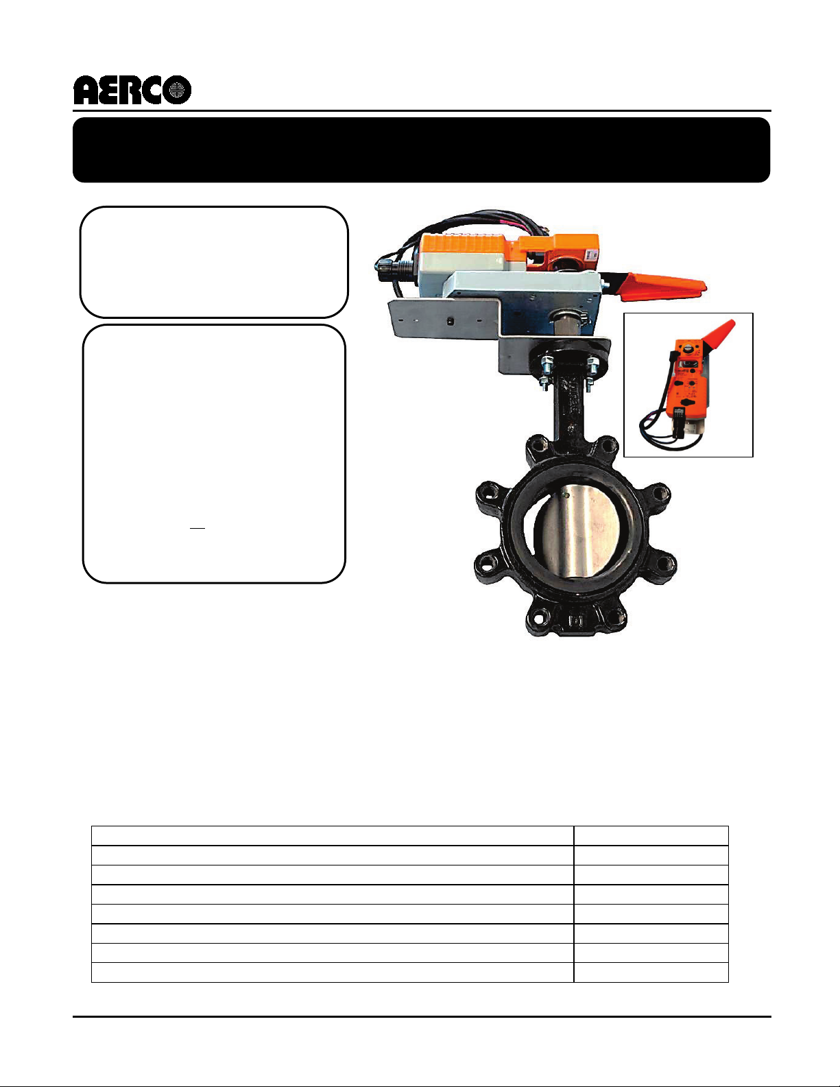
Valve Description:
AERCO P/N:
24-240VAC/24-125VDC, Spring Return Open Valve, 3”
92084-1
24-240VAC/24-125VDC, Dual-actuator, Spring Return Open Valve, 4”
92084-2
24V, Power Open/Power Close Valve, Fail-in-Place, 3”
92084-3
24V, Power Open/Power Close Valve, Fail-in-Place, 4”
92084-4
24V, Power Open/Power Close Valve, w/Electronic Fail-Safe, 3”
92084-5
24V, Power Open/Power Close Valve, w/Electronic Fail-Safe, 4”
92084-6
24V, Power Open/Power Close Valve, w/Electronic Fail-Safe, 6”
92084-7
Revised: 08/02/2012
Belimo
Installation
Applies to:
load conditions.
Belimo Motorized Valves
Belimo Motorized Control Valves and AERCO Part Numbers
Motorized Valve
• All Benchmark Boilers
• All KC1000 Boilers
Description of Document:
This TID provides instructions
for installing and wiring
Belimo motorized valves as
used to isolate an AERCO
Benchmark or KC1000 Boiler
from the system during low
Page 2

AERCO International, Inc. • 100 Oritani Dr. • Blauvelt, New York 10913 • Phone: 800-526-0288
Installing Belimo Motorized Valves on AERCO Benchmark Boilers
Technical instruction Document
TID-0028_0C
Technical Support:
1-800-526-0288
www.aerco.com
(Mon–Fri, 8am-5pm EST)
Disclaimer
The information contained in this manual is subject to change without notice from AERCO International,
Inc. AERCO makes no warranty of any kind with respect to this material, including but not limited to
implied warranties of merchantability and fitness for a particular application. AERCO International is not
liable for errors appearing in this manual. Nor for incidental or consequential damages occurring in
connection with the furnishing, performance, or use of this material.
PR2: 08/02/12 Page 2 of 20
Page 3

AERCO International, Inc. • 100 Oritani Dr. • Blauvelt, New York 10913 • Phone: 800-526-0288
Installing Belimo Motorized Valves on AERCO Benchmark Boilers
Technical instruction Document
TID-0028_0C
Table of Contents
1. Valve Application ..................................................................................................... 4
2. Valve Installation Location ....................................................................................... 4
3. Valve Orientation ...................................................................................................... 5
4. Valve Wiring .............................................................................................................. 5
5. Identifying BMK Pump Relay Option 69102 ............................................................ 7
6. Sequencing of Motorized Valve Through Building Automation System ............ 18
6.1 Prerequisites for Automation ........................................................................................ 18
6.2 Wiring/Programming for Automation ........................................................................... 18
6.3 Sequence of Automation Functions ............................................................................ 19
Belimo Motorized Control Valve Warranty ................................................................ 20
PR2: 08/02/12 Page 3 of 20
Page 4
AERCO International, Inc. • 100 Oritani Dr. • Blauvelt, New York 10913 • Phone: 800-526-0288
Installing Belimo Motorized Valves on AERCO Benchmark Boilers
Technical instruction Document
TID-0028_0C
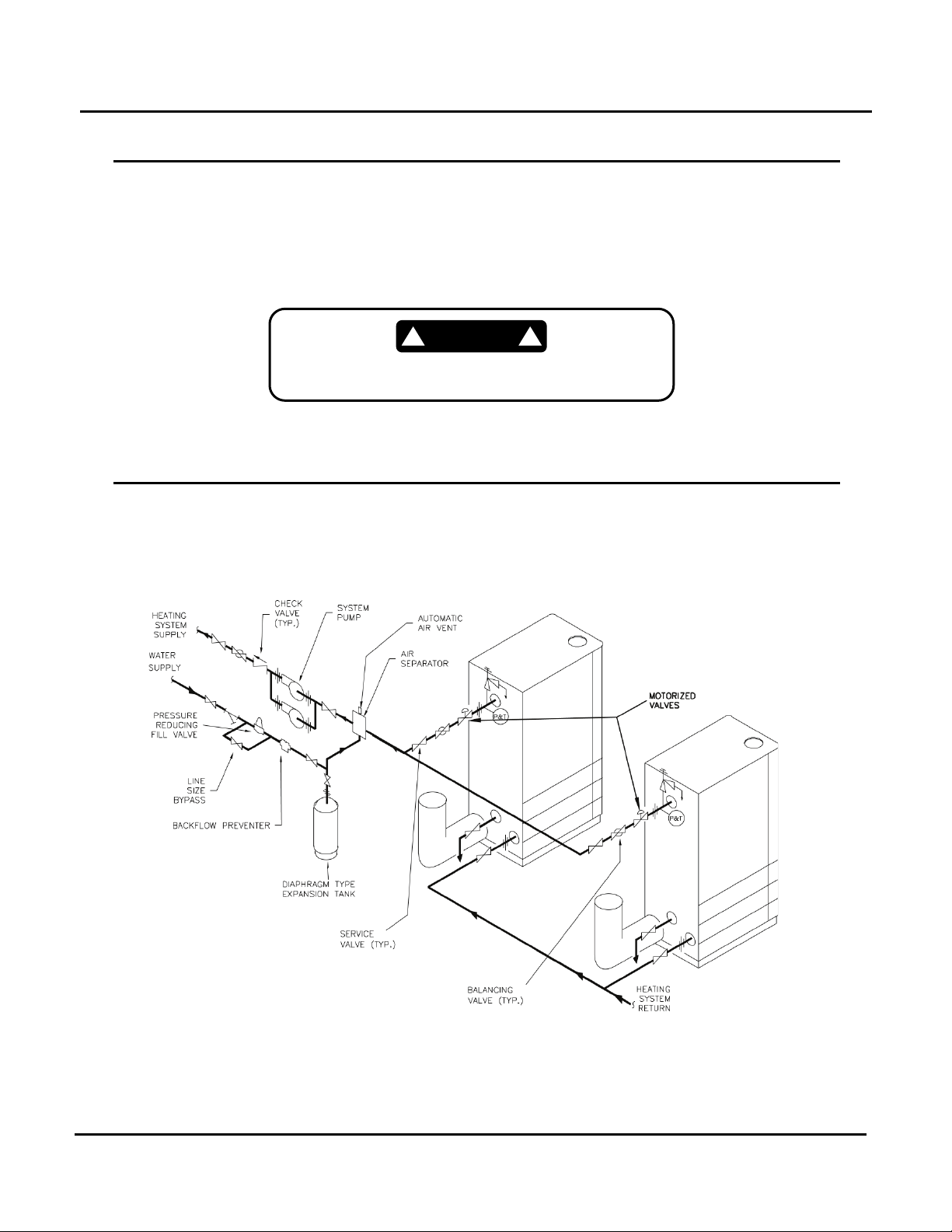
1. Valve Application
These valves are only used to isolate a boiler from the system during low load conditions. A separate
service valve MUST be installed for each boiler. See Figure 1 and Figure 2, which show typical
installation diagrams – local codes and authorities should be consulted for compliance. The primary
purpose of these diagrams is to illustrate the motorized valve location – see specific piping diagram
provided with the AERCO boiler for the rest of the piping details.
These valves do NOT qualify as service valves.
2. Valve Installation Location
a. Benchmark Boilers: Do NOT install the Motorized Control Valve directly against the outlet of the
boiler. The actuator will interfere with venting and boiler sheet metal.
b. Provide ample clearance from venting, water piping, gas piping, electrical, controls, and other system
components. The valve should be installed with a reasonable amount of “working space” around it to
allow room to be able to service the valve and use the manual lever.
Figure 1: Multiple Boiler Piping Schematic Showing Motorized Valve Locations for
AERCO Benchmark Boilers
PR2: 08/02/12 Page 4 of 20
Page 5
AERCO International, Inc. • 100 Oritani Dr. • Blauvelt, New York 10913 • Phone: 800-526-0288
Installing Belimo Motorized Valves on AERCO Benchmark Boilers
Technical instruction Document
TID-0028_0C
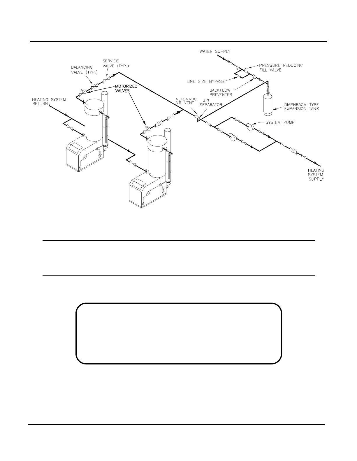
Figure 2: Multiple Boiler Piping Schematic Showing Motorized Valve Locations for
AERCO KC1000 Boilers
3. Valve Orientation
The valve can be oriented in any position as long as the actuator does not go below the horizontal plane.
See orientation guide from Belimo that is attached to the valve.
4. Valve Wiring
See Table 1 on the next page to determine which of the included diagrams to use.
IMPORTANT NOTE!
The valves are supplied with 3 feet of power cable (exception:
Valve PN 92084-7 is supplied with Screw Terminal for electrical
connection) and 3 feet of auxiliary switch cable. If the cables are
not long enough, we recommend that a distribution box be
connected. The power and auxiliary cables are permanently
connected to the valve and cannot be removed.
PR2: 08/02/12 Page 5 of 20
Page 6

AERCO International, Inc. • 100 Oritani Dr. • Blauvelt, New York 10913 • Phone: 800-526-0288
Installing Belimo Motorized Valves on AERCO Benchmark Boilers
Technical instruction Document
TID-0028_0C
Boiler Series
Motorized Valve
Controller (BVC)
Wiring
Use
Belimo 24-240VAC/24-
92084-2 (Dual Actuator)
24V, Power open/power
92084-7
120V 4-Boiler BVC
P/N 64095
120V 12-Boiler BVC
P/N 64096
24V 4-Boiler BVC
P/N 64097
24V 12-Boiler BVC
P/N 64098
24V, Power open/power
92084-7
24V 4-Boiler BVC
P/N 64097
Wiring Diagram Selection Guide for AERCO Boiler Valve Controller and AERCO supplied
Belimo Valves
How to use the below chart:
1. From the first column, identify the AERCO Boiler Series to which the Belimo valve will be
applied. If the Belimo valve is being installed on a BMK boiler that is already in the field, to
determine if the boiler is equipped with BMK Pump Relay Option 69102, see Figure 1 on
next page.
2. From the second column, identify the AERCO part number of the Belimo valve being used.
3. From the third column, identify which AERCO Boiler Valve Controller is being used in the
application.
4. Use the resulting wiring diagram from the last column.
Benchmark Boilers equipped
with BMK Pump Relay Option
69102
Benchmark Boilers NOT
equipped with BMK Pump
Relay Option 69102;
KC1000 Boilers
125VDC, Spring Return
Open Valves. AERCO Part
Numbers
92084-1
close Valves. Part Numbers
92084-3
92084-4
92084-5
92084-6
Belimo 24-240VAC/24-
125VDC, Spring Return
Open Valves. AERCO Part
Numbers
92084-1
92084-2 (Dual Actuator)
close Valves. Part Numbers
92084-3
92084-4
92084-5
92084-6
AERCO Boiler Valve
None SD-A-904
None SD-A-863
None SD-A-905
None SD-A-864
24V 12-Boiler BVC
P/N 64098
Diagram to
SD-A-906
SD-A-907
SD-A-909
SD-A-911
SD-A-908
SD-A-910
PR2: 08/02/12 Page 6 of 20
Page 7

AERCO International, Inc. • 100 Oritani Dr. • Blauvelt, New York 10913 • Phone: 800-526-0288
Installing Belimo Motorized Valves on AERCO Benchmark Boilers
Technical instruction Document
TID-0028_0C
Figure 3: Identifying the Presence of BMK Pump Relay Option 69102
5. Identifying BMK Pump Relay Option 69102
If the BMK Boiler features the label and relay as called out in Figure 3, above, then the unit is equipped
with BMK Pump Relay Option 69102.
PR2: 08/02/12 Page 7 of 20
Page 8

AERCO International, Inc. • 100 Oritani Dr. • Blauvelt, New York 10913 • Phone: 800-526-0288
Installing Belimo Motorized Valves on AERCO Benchmark Boilers
Technical instruction Document
TID-0028_0C
PR2: 08/02/12 Page 8 of 20
Page 9

AERCO International, Inc. • 100 Oritani Dr. • Blauvelt, New York 10913 • Phone: 800-526-0288
Installing Belimo Motorized Valves on AERCO Benchmark Boilers
Technical instruction Document
TID-0028_0C
PR2: 08/02/12 Page 9 of 20
Page 10

AERCO International, Inc. • 100 Oritani Dr. • Blauvelt, New York 10913 • Phone: 800-526-0288
Installing Belimo Motorized Valves on AERCO Benchmark Boilers
Technical instruction Document
TID-0028_0C
PR2: 08/02/12 Page 10 of 20
Page 11

AERCO International, Inc. • 100 Oritani Dr. • Blauvelt, New York 10913 • Phone: 800-526-0288
Installing Belimo Motorized Valves on AERCO Benchmark Boilers
Technical instruction Document
TID-0028_0C
PR2: 08/02/12 Page 11 of 20
Page 12

AERCO International, Inc. • 100 Oritani Dr. • Blauvelt, New York 10913 • Phone: 800-526-0288
Installing Belimo Motorized Valves on AERCO Benchmark Boilers
Technical instruction Document
TID-0028_0C
PR2: 08/02/12 Page 12 of 20
Page 13

AERCO International, Inc. • 100 Oritani Dr. • Blauvelt, New York 10913 • Phone: 800-526-0288
Installing Belimo Motorized Valves on AERCO Benchmark Boilers
Technical instruction Document
TID-0028_0C
PR2: 08/02/12 Page 13 of 20
Page 14

AERCO International, Inc. • 100 Oritani Dr. • Blauvelt, New York 10913 • Phone: 800-526-0288
Installing Belimo Motorized Valves on AERCO Benchmark Boilers
Technical instruction Document
TID-0028_0C
PR2: 08/02/12 Page 14 of 20
Page 15

AERCO International, Inc. • 100 Oritani Dr. • Blauvelt, New York 10913 • Phone: 800-526-0288
Installing Belimo Motorized Valves on AERCO Benchmark Boilers
Technical instruction Document
TID-0028_0C
PR2: 08/02/12 Page 15 of 20
Page 16

AERCO International, Inc. • 100 Oritani Dr. • Blauvelt, New York 10913 • Phone: 800-526-0288
Installing Belimo Motorized Valves on AERCO Benchmark Boilers
Technical instruction Document
TID-0028_0C
PR2: 08/02/12 Page 16 of 20
Page 17

AERCO International, Inc. • 100 Oritani Dr. • Blauvelt, New York 10913 • Phone: 800-526-0288
Installing Belimo Motorized Valves on AERCO Benchmark Boilers
Technical instruction Document
TID-0028_0C
PR2: 08/02/12 Page 17 of 20
Page 18

AERCO International, Inc. • 100 Oritani Dr. • Blauvelt, New York 10913 • Phone: 800-526-0288
Installing Belimo Motorized Valves on AERCO Benchmark Boilers
Technical instruction Document
TID-0028_0C
mA OUT
RS-485
COMM.
+
-
+
-
ANALOG IN
SENSOR COMMON
OUTDOOR SENSOR IN
REMOTE INTL'K IN
B.M.S. (PWM) IN
SHIELD
+
-
+
-
(AIR) AUX SENSOR IN
NOT USED
EXHAUST SWITCH IN
DELAYED INTL'K IN
FAULT RELAY
120 VAC, 5A, RES
AUX RELAY
120 VAC, 5A, RES
G
RELAY CONTACTS:
120 VAC, 30 VDC
5 AMPS RESISTIVE
DANGER
120 VAC USED
IN THIS BOX
NOT USED
NOT USED
NC
COM
NO
NC
COM
NO
NOT USED
0 – 10V
AGND
Delayed Interlock Connections
Auxiliary Relay Connections
6. Sequencing of Motorized Valve Through Building Automation System
6.1 Prerequisites for Automation
1. Motor Operated Valve (MOV) for each boiler must have a proof of open switch.
2. Check with valve manufacturer for the time it requires for the valve to fully open. Opening time
must not exceed 110 seconds.
6.2 Wiring/Programming for Automation
1. Use the Aux Relay of the C-More control system to signal the Building Automation System (BAS)
that a boiler is in demand.
2. Wire the proof of open switch of the MOV to the Delayed Interlock of the C-More control system.
Figure 4: C-More PCB Showing Delayed and Remote Interlock Connections
3. Program the Aux Start On Delay on the C-More to allow enough time for the valve to fully open
before firing the boiler. The Aux Start On Delay is located in the Configuration Menu of the C-
PR2: 08/02/12 Page 18 of 20
More control system. Range is 0 to 120 seconds.
4. The BAS must incorporate a delay when closing valves once the demand is satisfied. This will
allow the boiler to dissipate excess heat. Recommended delay is 2 minutes minimum. More time
may be required dependent on the system design.
5. The BAS must be programmed so when there is no demand from the entire system (all boilers
are off), all boiler MOVs are opened.
Page 19

AERCO International, Inc. • 100 Oritani Dr. • Blauvelt, New York 10913 • Phone: 800-526-0288
Installing Belimo Motorized Valves on AERCO Benchmark Boilers
Technical instruction Document
TID-0028_0C
NOTE
For complete wiring connections, see Belimo’s Installation and Maintenance Instructions shipped with the
http://www.belimo.us/belimo/media//Instructions/Installation/BFV_Instruction_Sheet.pdf
valve and also available online at:
6.3 Sequence of Automation Functions
1. When a boiler is in demand, its Aux Relay will close, signaling the BAS. The Aux Start On Delay
timer starts.
2. The BAS opens the MOV of the corresponding boiler.
3. When the valve has fully opened, its proof of open switch is made, closing the delayed interlock
of the boiler — allowing the boiler to fire.
4. When the demand is satisfied on a corresponding boiler, the BAS will keep its valve open for at
least 2 minutes before closing.
5. When there is no more demand from the entire system (all boilers are off), the BAS will open all
boiler MOVs.
6. The next time there is a demand on a boiler, this sequence repeats and the BAS closes the MOV
of the other boilers that have no demand.
PR2: 08/02/12 Page 19 of 20
Page 20

AERCO International, Inc. • 100 Oritani Dr. • Blauvelt, New York 10913 • Phone: 800-526-0288
Installing Belimo Motorized Valves on AERCO Benchmark Boilers
Technical instruction Document
TID-0028_0C
Belimo Motorized Control Valve Warranty
The Belimo Motorized Control Valve Warranty is conditionally warranted against failure due to
defect in materials for (2) two years from shipment.
AERCO shall accept no responsibility if such item has been improperly installed, operated, or
maintained or if the buyer has permitted any unauthorized modification, adjustment, and/or
repairs to the item.
The warranty as set forth on the back page of the Technical Instructions Document is in lieu of
and not in addition to any other express or implied warranties in any documents, or under any
law. No salesman or other representative of AERCO has any authority to expand warranties
beyond the face of the said warranty and purchaser shall not rely on any oral statement except as
stated in the said warranty. An Officer of AERCO must do any modifications to this warranty in
writing. AERCO MAKES NO WARRANTY OF MERCHANTABILITY OR FITNESS
FOR PARTICULAR PURPOSE OR ANY OTHER EXPRESS OR IMPLIED
WARRANTIES. AERCO disclaims all responsibility for any special, incidental or
consequential damages. Any claim relating to the product must be filed with AERCO not later
than 14 days after the event-giving rise to such claim. Any claims relating to this product shall be
limited to the sale price of the product at the time of sale. The sale of the product is specifically
conditioned upon acceptance of these terms.
CONDITIONS OF WARRANTY:
Should a Belimo Motorized Control Valve fail for any of the above reasons within the specified
time period from the date of original shipment(s), AERCO shall, at its option, modify, repair or
exchange the defective item. AERCO shall have the option of having the item returned, FOB its
factory, or to make field replacements at the point of installation. In no event shall AERCO be
held liable for replacement labor charges or for freight or handling charges.
AERCO shall accept no responsibility if such item has been improperly installed, operated, or
maintained or if the buyer has permitted any unauthorized modification, adjustment, and/or
repairs to the item. The use of replacement parts not manufactured or sold by AERCO will void
any warranty, express or limited.
In order to process a warranty claim, a formal purchase order number is required prior to
shipment of any warranty item. In addition, the warranty must be pre-authorized by AERCO.
Warranty Rev: 6/10/11
© AERCO International, Inc., 2011
PR2: 08/02/12 Page 20 of 20
 Loading...