

Page 1

GF-115-C
OMM-0084_0D
AERCO International, Inc. • 100 Oritani Dr. • Blauvelt, NY 10913 • Ph: 800-526- 0288
USER MANUAL
Other manuals for this product include:
Gas Fired Boiler Systems
Modulex E8 Controller
• MLX-303
E8 Controller for MLX Series Boilers
Boiler Communications Module (BCM)
for MLX Series Boilers
Installation, Operation, and Maintenance
Modulating, Condensing,
Hot Water Boiler Models:
• MLX-454
• MLX-606
• MLX-757
• MLX-909
• MLX-1060
And BC Module (BCM)
.
• GF-115-H MLX Series Boiler Manual
• GF-115-G MLX Gas Design Guide
• GF-115-P-H MLX Piping Guide
• GF-115-V MLX Venting Guide
• GF-115-E MLX Electrical Power Guide
Revised: 11/30/2012
PR1: 11/30/12 Page 1 of 112
Page 2

GF-115-C
Modulex E8 Controller and BCM
Operations and Maintenance Manual
OMM-0084_0D
Technical Support:
1-800-526-0288
www.aerco.com
(Mon–Fri, 8am-5pm EST)
AERCO International, Inc. • 100 Oritani Dr. • Blauvelt, New York 10913 • Phone: 800-526-0288
Disclaimer
The information contained in this manual is subject to change without notice from AERCO International,
Inc. AERCO makes no warranty of any kind with respect to this material, including but not limited to
implied warranties of merchantability and fitness for a particular application. AERCO International is not
liable for errors appearing in this manual. Nor for incidental or consequential damages occurring in
connection with the furnishing, performance, or use of this material.
PR1: 11/30/12 Page 2 of 112
AERCO International, Inc. • 100 Oritani Dr. • Blauvelt, NY 10913 • Ph: 800-526- 0288
Page 3

GF-115-C
OMM-0084_0D
AERCO International, Inc. • 100 Oritani Dr. • Blauvelt, NY 10913 • Ph: 800-526- 0288
Table of Contents
Table of Contents .......................................................................................... 3
1. INTRODUCTION ..................................................................................... 7
1.1 Safety and Warnings ........................................................................................ 7
2. E8 CONTROLLER AND BCM DESCRIPTION .......................................... 9
2.1 E8 Controller Features And Functions ........................................................... 9
2.2 BCM Features And Functions ....................................................................... 10
3. E8 CONTROLLER OPERATION ............................................................ 11
3.1 NORMAL Mode Operation (Door Closed)..................................................... 11
3.1.1 NORMAL Mode Display Functions ................................................................... 11
3.1.2 HEATING Mode Selection (in NORMAL Mode) ............................................. 12
3.1.3 MENU Mode Operation (Door Open) ................................................................ 13
3.2 Software Menus .............................................................................................. 14
3.2.1 Basic Menu/Sub-Menu Navigation and Selection .............................................. 15
3.2.2 Basic Parameter Navigation, Selection, and Revision ........................................ 16
4. E8 CONTROLLER MENUS AND SUB-MENUS ...................................... 17
4.1 DISPLAY Menu ............................................................................................... 18
4.2 USER Menu ..................................................................................................... 21
4.3 TIME PROGRAM Menu and Sun-Menus ....................................................... 24
4.4 EXPERT Menu and Sub-Menus ..................................................................... 25
4.4.1 Available V-Curve Preset Voltage Curves for 0 – 10 Volt Input ....................... 31
4.5 EXPERT HS Menu (Not Used) ...................................................................... 32
4.6 GENERAL Menu ............................................................................................. 32
4.6.1 DATE / TIME Menu ........................................................................................... 32
4.6.2 SERVICE Menu .................................................................................................. 34
4.7 E8 Controller Initial Startup ........................................................................... 37
4.7.1 CAP/MODULE Function (Maximum Kilowatts per Burner) ............................ 39
4.7.1 Available Settings for Relay Functions 1 – 4 ...................................................... 40
5. E8 OPERATING MODE: Set-up and Programming .................................. 41
5.1 Indoor/Outdoor Reset Mode .......................................................................... 41
5.1.1 Wiring Connections............................................................................................. 41
5.1.2 Indoor/Outdoor Reset Operation Configuration ................................................. 41
5.1.3 Viewing the Boiler Setpoint ................................................................................ 43
5.2 Constant Set Point Mode ............................................................................... 43
5.2.1 Wiring Connections............................................................................................. 44
5.2.2 Constant Setpoint Mode Configuration............................................................... 44
5.2.3 Viewing Constant Set Point ................................................................................ 44
PR1: 11/30/12 Page 3 of 112
Page 4

GF-115-C
Modulex E8 Controller and BCM
Operations and Maintenance Manual
OMM-0084_0D
5.2.4 Configuring Set Point High and Low Limits Per Outside Temperature Sensor . 44
5.3 0 to 10 Volt Remote Set Point Mode ............................................................. 47
5.3.1 Remote Signal Source Wiring Connections ........................................................ 47
5.3.2 Configuring Remote Signal Source..................................................................... 48
5.3.3 Setting the Voltage and Set Point Limits for U1/U2 and T1/T2 ......................... 49
5.3.4 Setting the Curve 11-UO Voltage ....................................................................... 50
5.3.5 Viewing the Set Point .......................................................................................... 51
5.4 Domestic Hot Water Operation Using A Tank Sensor ................................ 51
5.4.1 Sensor Wiring Connections ................................................................................. 51
5.4.2 Configuring the Controller for DHW With a Tank Sensor ................................. 52
5.4.3 Setting the DHW Set Point ................................................................................. 53
5.4.4 Displaying Temperatures Associated With DHW .............................................. 54
5.5 DHW Operation Using an Aquastat .............................................................. 55
5.5.1 Sensor Wiring Connections ................................................................................. 55
5.5.2 Configuring the Controller for DHW With an Aquastat ..................................... 55
5.5.3 Setting the DHW Set Point ................................................................................. 55
5.5.4 Displaying Temperatures Associated With DHW .............................................. 55
5.6 Boiler & Pump Enable/Disable ...................................................................... 55
6. CONNECTION DIAGRAMS .................................................................... 57
6.1 Power Terminal Assignments ....................................................................... 58
6.2 Sensor Terminal Assignments ...................................................................... 59
7. BOILER COMMUNICATIONS MODULE (BCM) ..................................... 61
7.1 Boiler Communications Module (BCM) Description ................................... 61
7.2 BCM Fault Relay ............................................................................................. 63
7.2.1 BCM Fault Relay Wiring .................................................................................... 63
7.2.2 Clearing Faults .................................................................................................... 63
7.3 BCM Configured as Back-Up Controller ...................................................... 64
7.3.1 BCM Back-Up Controller Wiring ....................................................................... 64
7.4 BCM Configured as Primary Controller Utilizing Modbus .......................... 65
7.4.1 Operating Scenario .............................................................................................. 65
7.4.2 Physical Modbus RS485 Wiring ......................................................................... 66
7.4.3 Disconnecting the E8 from the E-Bus on the BCM Board. ................................ 67
7.4.4 AERCO BMS II/ACS Master to BCM Slave Wiring Connections. ................... 68
7.4.5 EMS or BAS Master to BCM Slave Wiring Connections .................................. 68
7.5 RS485 Loop Termination Resistors and Bias .............................................. 68
7.5.1 Master AERCO BMS II/ACS or EMS/BAS Terminating Resistor and Bias ..... 68
7.5.2 BCM Controller Terminating Resistor and Bias ................................................. 69
7.6 Modbus Network Wiring Diagram ................................................................. 70
7.7 Modbus Software Set-Up ............................................................................... 73
7.7.1 BCM Set-Up for Modbus Operation ................................................................... 73
PR1: 11/30/12 Page 4 of 112
AERCO International, Inc. • 100 Oritani Dr. • Blauvelt, NY 10913 • Ph: 800-526- 0288
Page 5

GF-115-C
Modulex E8 Controller and BCM
Operations and Maintenance Manual
OMM-0084_0D
7.7.2 Monitoring and Configuration Only ................................................................... 74
7.7.3 AERCO BMS II/ACS Modbus Control and Monitoring .................................... 74
7.7.4 Modbus Remote Setpoint Control and Monitoring ............................................. 74
7.7.5 EMS or BAS Set-Up As Master to BCM Controller Slaves ............................... 74
7.8 Multiple Modulex Boiler Heating Mode – Utilizing a BMS II or ACS ........... 74
7.8.1 Sequence of Operation (Example: Four-Modulex boiler installation) ................ 75
8. E8 CONTROLLER MENU LISTINGS ..................................................... 77
8.1 DISPLAY Menu ............................................................................................... 77
8.2 USER Menu ..................................................................................................... 79
8.3 TIME PROGRAM Menu .................................................................................. 81
8.4 EXPERT Menu ................................................................................................ 84
8.5 GENERAL Menu ............................................................................................. 89
8.5.1 DATE / TIME Sub-Menu ................................................................................... 89
8.5.2 SERVICE Sub-Menu .......................................................................................... 90
9. BCM MODBUS AND ADDRESS ASSIGNMENTS ................................... 93
9.1 BCM Modbus Communication & Support Requirements ........................... 93
9.1.1 Function Codes .................................................................................................... 93
9.1.2 Modbus Support Requirements ........................................................................... 93
9.2 BCM Controller Standard Holding Register Assignments ......................... 94
9.2.1 BCM Controller Standard Input Register Assignments ...................................... 94
9.2.2 BCM Controller Standard Holding Register Assignments ................................. 94
10. E8, BCM, AND BMM FAULT CODES ................................................. 101
10.1 Processing and Clearing Fault Codes ........................................................ 102
10.2 Fault Codes and Descriptions ..................................................................... 103
10.2.1 E8 Controller Fault Codes ............................................................................. 104
10.2.2 BCM (Boiler Communications Module) Fault Codes ................................... 106
10.2.3 BMM (Burner Management Module) Fault Codes ....................................... 108
PR1: 11/30/12 Page 5 of 112
AERCO International, Inc. • 100 Oritani Dr. • Blauvelt, NY 10913 • Ph: 800-526- 0288
Page 6

GF-115-C
Modulex E8 Controller and BCM
Operations and Maintenance Manual
OMM-0084_0D
(This page left intentionally blank)
PR1: 11/30/12 Page 6 of 112
AERCO International, Inc. • 100 Oritani Dr. • Blauvelt, NY 10913 • Ph: 800-526- 0288
Page 7
GF-115-C
OMM-0084_0D
AERCO International, Inc. • 100 Oritani Dr. • Blauvelt, NY 10913 • Ph: 800-526- 0288
WARNING
!
!
CAUTION
!
!
DANGER
!
!
DANGER
!
!
1. INTRODUCTION
The information in this manual provides a guide to the operation of the Modulex Boiler using
the E8 Controller and the Boiler Communications Module (BCM) mounted on the front of the
unit. Sections 3, 4, 5, 6, and 8 provide descriptions and procedures for the E8 Controller.
Sections 7, 9, and 10 provide similar information for the BCM.
It is imperative that the initial startup procedures be performed by factory trained personnel.
Operation by untrained personnel, prior to the initial startup, will void the equipment warranty.
In addition, CAUTIONS and WARNINGS in this manual must be observed at all times.
1.1 Safety and Warnings
The following defined symbols are used throughout this manual to notify the reader of potential
hazards of varying risk levels.
Indicates an imminently hazardous situation, which if not avoided,
WILL result in death or serious injury.
Indicates a potentially hazardous situation, which if not avoided,
MAY result in death or serious injury.
Indicates a potential hazardous situation, which if not avoided,
COULD result in minor or moderate injury. Also may caution
against unsafe practices.
Note that all hazard notifications and notes are presented enclosed in a rectangle with filleted
(round) corners, as shown below, in order to differentiate them from the main text.
It is of utmost importance to observe all CAUTIONS and
WARNINGS presented in this manual to avoid injury, death, and
damage to the equipment. Failure to properly heed safety
warnings and cautions may result in the voiding of applicable
warranties.
PR1: 11/30/12 Page 7 of 112
Page 8

GF-115-C
Modulex E8 Controller and BCM
Operations and Maintenance Manual
OMM-0084_0D
(This page left intentionally blank)
PR1: 11/30/12 Page 8 of 112
AERCO International, Inc. • 100 Oritani Dr. • Blauvelt, NY 10913 • Ph: 800-526- 0288
Page 9
GF-115-C
OMM-0084_0D
AERCO International, Inc. • 100 Oritani Dr. • Blauvelt, NY 10913 • Ph: 800-526- 0288
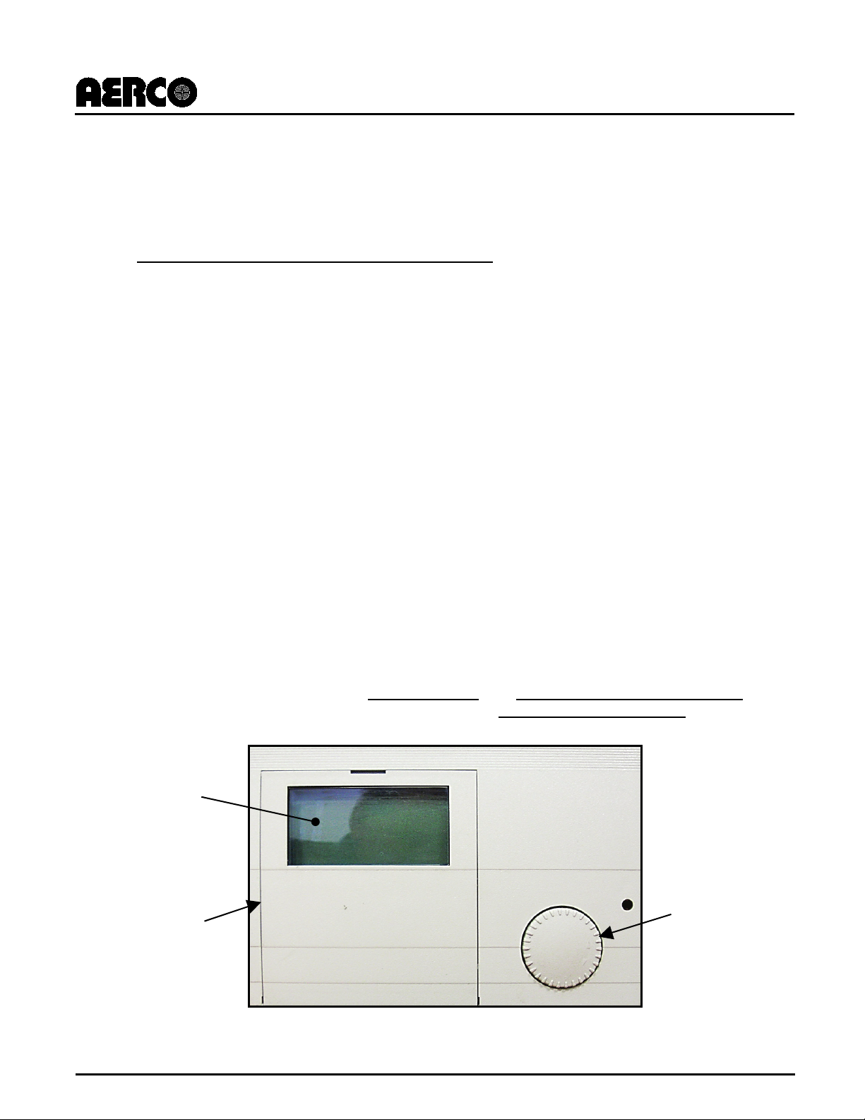
Rotary Knob
LCD Display
Hinged Cover
2. E8 CONTROLLER AND BCM DESCRIPTION
Modulex boilers contain advanced and reliable electronic controls, which includes the E8
Controller and the BCM (Boiler Communications Module), providing comprehensive
programming and monitoring of the Modulex boiler and its functions. Features and functions of
the E8 Controller are described in the following sections.
2.1 E8 Controller Features And Functions
A standard component included in Modulex units, the E8 Controller is responsible for the
staging and modulation of individual thermal heating modules in a Modulex boiler and also
monitors supply and return water temperatures and domestic hot water zones.
The E8 Controller is housed in a compact enclosure measuring 5.7” (145 mm) x 3.9” (100 mm).
The Controller is mounted on the front of the Modulex Boiler and contains all of the controls,
indicators and displays necessary to adjust, operate and troubleshoot the Modulex Boiler. The
E8 features the following functions for Modulex boilers:
• Shares the heating load among as many of the boiler's thermal heating modules as
possible. maximizing the overall operating efficiency of the boiler.
• Provides access to all testing/programming parameters of each individual heating module:
operation test, operation time, boiler freeze protection and pump's anti seize program.
• Drives lead-lag burner operation based on operating hours. The boiler module with the least
burner operating hours is the first to start and the burner with the most operating hours is the
first to stop.
• Supports DHW (Domestic Hot Water) production using a dedicated sensor to control a
dedicated pump or 3-way diverting valve for storage tank temperature control.
• Supports a manual operation service mode to control individual modules during
troubleshooting or combustion calibration procedures.
• Drives diagnostics such as relay and senor testing.
• Supports Modbus integration with AERCO BMS II and AERCO Control System (ACS) or
Building Automation Systems. AERCO also offers a Communication Gateway to support
BACnet, Lonworks and N2 system integration.
Window
(in closed
position)
Figure 2-1: Modulex E8 Controller Front Panel
PR1: 02/23/12 Page 9 of 112
Page 10
GF-115-C
Modulex E8 Controller and BCM
Operations and Maintenance Manual
OMM-0084_0D
2.2 BCM Features And Functions
The BCM (Boiler Communications Module) is an electronic module in Modulex boilers (one per
burner), which supports full interoperability to BAS (Building Automation Systems) via Modbus
protocol to make remote communications and control possible. In addition, it provides
customers with a remote alarm contact to notify customers of faults detected within any of
boiler's multiple thermal modules. Finally, in the event the boiler's master controller stops
working, the BCM also takes over operations of the boiler.
As a back-up controller, the BCM further increases the reliability of a product line already known
for its uniquely redundant design. Each Modulex boiler combines between two and seven
independent, 151,500 BTU/hr., pre-assembled thermal modules housed in a common
enclosure. Each module has its own dedicated controller with a combustion safeguard, variablespeed fan, modulating gas valve, electronic ignition, modulating burner, flow temperature
sensor, thermostat and heat exchanger. The independent operation of these thermal modules
increases each boiler's overall reliability. If a single module requires maintenance or repair, the
other module(s) in the boiler can maintain the system load requirements -- thereby providing a
level of redundancy that was previously only realized in multi-boiler installations.
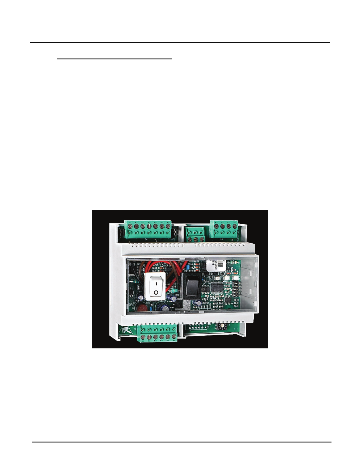
A photo of the module is shown in Figure 2-2 below. Additional information for the BCM
component can be found in Section 7, 9, and 10.
Figure 2-2: Modulex BCM (Boiler Communications Module)
PR1: 11/30/12 Page 10 of 112
AERCO International, Inc. • 100 Oritani Dr. • Blauvelt, NY 10913 • Ph: 800-526- 0288
Page 11
GF-115-C
OMM-0084_0D
AERCO International, Inc. • 100 Oritani Dr. • Blauvelt, NY 10913 • Ph: 800-526- 0288
Heating Mode display symbol. The display symbols apply to all internal heating
circuits for which a separate heating mode has been selected. Note that each
H B E
D
I G F C A
3. E8 CONTROLLER OPERATION
The E8 Controller operates in NORMAL Mode when the controller door is closed, which allows
for monitoring the boiler status through the display window and setting the HEATING Mode.
When the door is opened, the unit enters MENU Mode, and in this mode the boiler may be
initialized, configured, and adjusted. The controls and display for the E8 controller are described
in the following sub-sections.
3.1 NORMAL Mode Operation (Door Closed)
When the hinged door is closed on the E8, the unit is in NORMAL Mode.
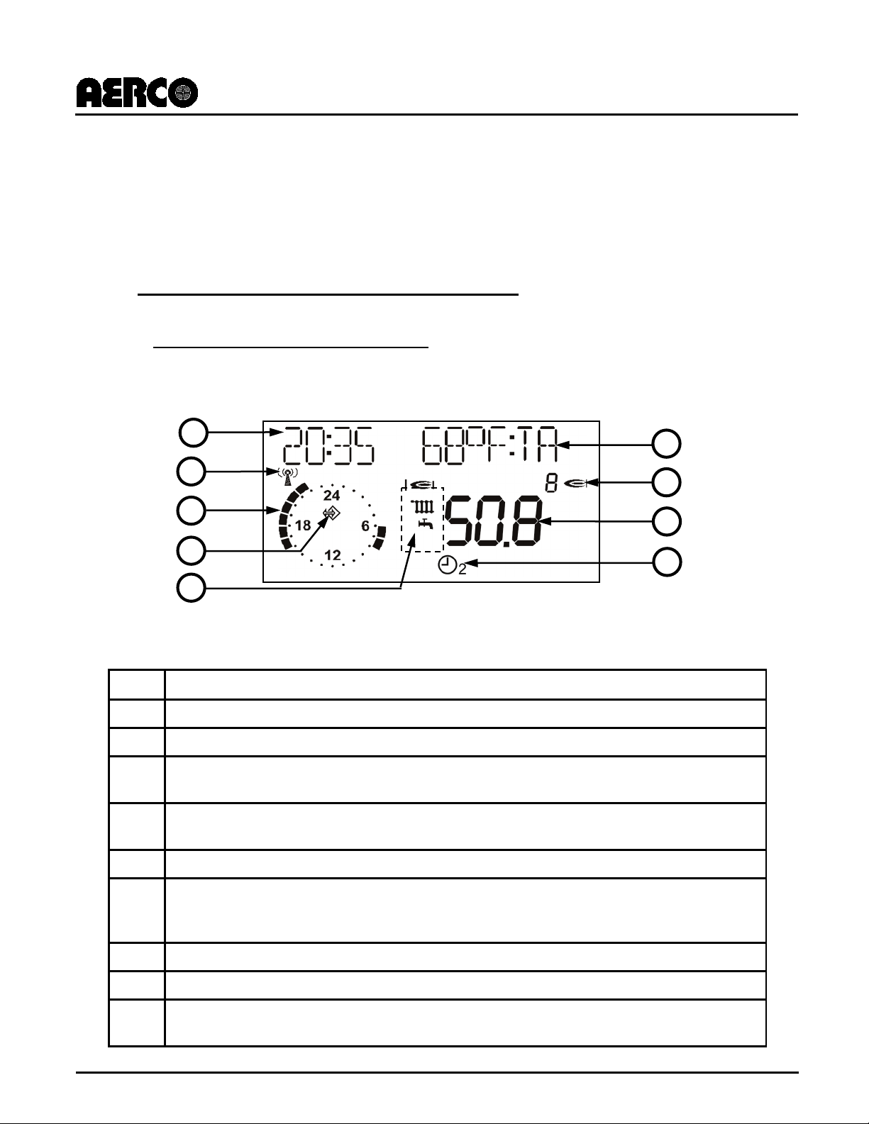
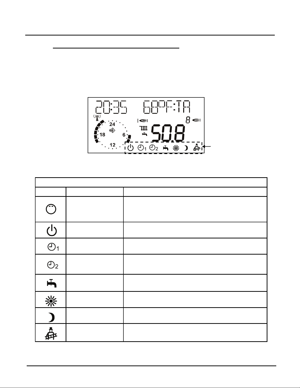
3.1.1 NORMAL Mode Display Functions
Figure 3-1 describes the types of information provided on the LCD display when in NORMAL
Mode (door closed). Note that the display in the illustration is only an example, and that an E8
Controller in service will show information appropriate for its configuration.
Figure 3-1: E8 LCD Display in NORMAL Mode (Door Closed)
E8 Controller Display in NORMAL Mode
Item Functions
A
Current time (24 hour format)
B
DCF reception OK (only if receiver is connected via eBUS)
Display of the active heating program for the first heating circuit (here: 6:00 to 08:00
C
a.m. and 4:00 to 10:00 p.m.)
Bus icon (if this icon does not appear, check data line to connected CAN controllers
D
=> check eBUS via DISPLAY level)
E
Status display: Shows symbols for Internal Burner 1 Relay ON; Heating Mode; Hot Water Preparation.
F
symbol occupies a different space across the display bottom. See Figure 3-2.
G
Display of current temperature of HS 1 or header temperature when cascading.
H
Display of number of active heat generators (only applies when cascading).
Selectable display and Error Codes (refer to "DISPLAY SEL" parameter in the USER
I
menu).
PR1: 02/23/12 Page 11 of 112
Page 12
GF-115-C
Modulex E8 Controller and BCM
Operations and Maintenance Manual
OMM-0084_0D
AERCO International, Inc. • 100 Oritani Dr. • Blauvelt, NY 10913 • Ph: 800-526- 0288
SYMBOL
MODE NAME
DESCRIPTION
Turn the Rotary Knob to select the heating mode
heating mode is indicated by a symbol at
the bottom of the display. It takes effect when the setting
is not changed for 5 seconds.
HEATING Mode Symbols:
3.1.2 HEATING Mode Selection (in NORMAL Mode)
Heating modes may be selected using the Rotary Knob on the controller when the hinged door
is in the closed position (NORMAL Mode). As the Rotary Knob is turned, each appropriate
heating mode symbol is displayed, in turn, along the lower edge of the display.
Mode changes take effect when the setting is not changed for 5 seconds. The symbols and
description for the available heating modes are shown in Figure 3-2.
Only currently selected
mode will be displayed.
Figure 3-2: Heating Mode Display Symbols and Description
E8 Controller HEATING Modes
Heating Mode
Selection
Standby / OFF
Automatic Mode 1
Automatic Mode 2
Summer Mode
Day
Mode
Night
Mode
required. The
(Heat OFF and hot water (HW) preparation OFF, only
frost protection mode)
(Heat according to timer program 1; HW according to
HW program)
(Heat according to timer program 2; HW according to
HW program)
(Heating OFF, HW according to HW program)
(24 Hour heating with comfort temperature 1; HW
according to HW program)
(24 Hour heating with reduced temperature; HW
according to program)
Service Mode
PR1: 11/30/12 Page 12 of 112
(Automatic reset after 15 minutes. Boiler regulated at
max boiler temperature)
Page 13
GF-115-C
Modulex E8 Controller and BCM
Operations and Maintenance Manual
OMM-0084_0D
AERCO International, Inc. • 100 Oritani Dr. • Blauvelt, NY 10913 • Ph: 800-526- 0288
Insert narrow screwdriver deep into holes and lift up
When lit, this LED indicates that the value shown in the display can be
D
position (10/2 o’clock) screwdriver adjustable switch.
FLOW (in EXPERT/HEAT
F
E
D
C B A
G
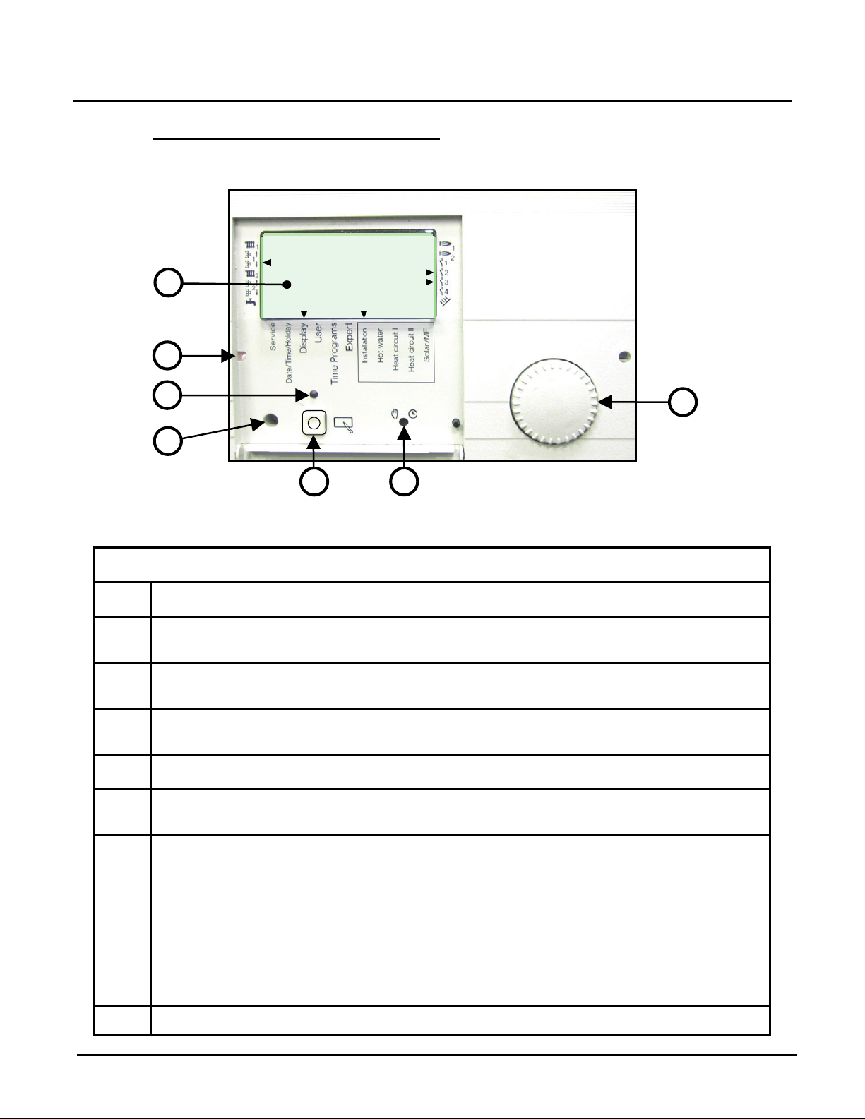
3.1.3 MENU Mode Operation (Door Open)
Opening the E8 controller hinged door reveals the E8 controls (Figure 3-3) and initiates the
MENU Mode, which enables access to an extensive set of software menus.
INSTALLATION
Figure 3-3: E8 Controller Controls (cover open in MENU Mode)
E8 Controller Controls and Indicators
ITEM FUNCTION
A
B
C
E
F
LCD display: Selected Menu/Sub-menus, parameter names/values, and selected
busses are indicated in the LCD display when in MENU Mode.
Mounting Key Access Holes:
controller to remove.
Change LED:
changed using the Rotary Knob (A).
Optical Adaptor: For PC connection
Program Key: Used to select a sub-menu level, select a parameter value to change, or
save a new parameter value.
Manual/Automatic Switch: A 2-
Normally, this switch is set to the Automatic (2 o’clock) position to allow program control
of the boiler. When set to the Manual (10 o’clock) position, a flashing “EMERG –
MODE” message is displayed. Heating Circuit 1 (HC1) pump and the first burner stage
are switched on. Pumps for Heating Circuit 2 (HC2) and Domestic Hot Water (DHW) will
also be switched on if sensors are installed and enabled. The pump(s) will turn off when
the flow temperature reaches the value set for MAX TCIRCUIT 1 menu). The first burner stage will cut off when the boiler temperature
reaches the value set for MAX T-MODUL (in EXPERT/INSTALLATION menu).
G Rotary Knob: Used to navigate through menus and parameters or adjust parameters.
PR1: 11/30/12 Page 13 of 112
Page 14
GF-115-C
Modulex E8 Controller and BCM
Operations and Maintenance Manual
OMM-0084_0D
AERCO International, Inc. • 100 Oritani Dr. • Blauvelt, NY 10913 • Ph: 800-526- 0288
INSTALLATION
HOT WATER
HEAT CIRCUIT I
HEAT CIRCUIT II
SOLAR/MF
INSTALLATION
HOT WATER
HEAT CIRCUIT I
HEAT CIRCUIT II
SOLAR/MF
CIRCL TIME
HOTW-PROG
HTG-PROG 1
HTG-PROG 2
INSTALLATION
HOT WATER
HEAT CIRCUIT I
HEAT CIRCUIT II
SOLAR/MF
SERVICE
DATE/TIME
HOLIDAY
CLOCK CHANGE
3.2 Software Menus
Software menus are divided into five main menus, each with a set of sub-menus (Table 3-1).
The rotary knob on the front of the E8 Controller is used to sequentially cycle through the
menus and the sub-menus. Two small arrows at the bottom of the display point to the selected
menu and sub-menu name, respectively. Note that some menus and sub-menus are read-only
or not available, according to the boiler used and the initial startup configuration.
NOTE
The menu processing steps presented in this manual assume that all required
(one-time) INSTALLATION menu items have already been entered at setup. It
should be noted that whenever the unit is powered down and then powered up
again, the INSTALLATION menu will reappear. When this occurs, the
INSTALLATION menu items DO NOT need to be reentered. Normally, after entry
of the required initial INSTALLATION menu entries, turning the Rotary Knob
clockwise will automatically advance the Controller to the DISPLAY menu group.
All items in this group are “Read Only” and cannot be changed.
See Sub-section 4.7, E8 Controller Initial Startup for more information about
initial setup and configuration of the E8 Controller.
Table 3-1: Main Menus and Sub-Menus
MAIN MENUS SUB-MENUS
DISPLAY
USER
TIME
PROGRAMS
EXPERT
EXPERT HS
INSTALLATION
GENERAL
PR1: 11/30/12 Page 14 of 112
Page 15
GF-115-C
Modulex E8 Controller and BCM
Operations and Maintenance Manual
OMM-0084_0D
AERCO International, Inc. • 100 Oritani Dr. • Blauvelt, NY 10913 • Ph: 800-526- 0288
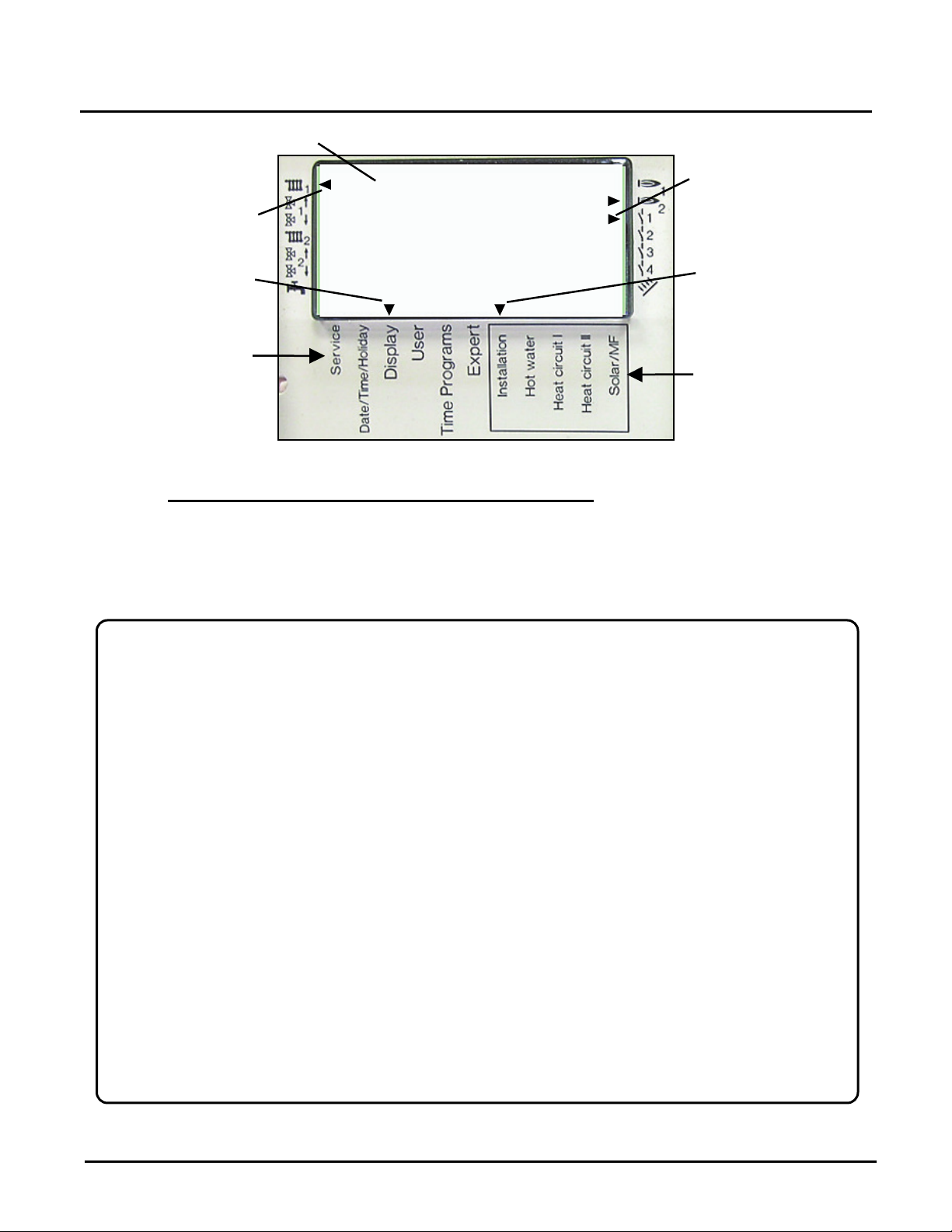
Points down to
Points right to
Points left to
Points down to
Sub-MENU
MENU
Sub-MENU Name
Selected
Buss(es)
Selected Bus(es)
Selected
Selected
MENU Name
Names
Sub-MENU
Name
Names
Figure 3-4: E8 Display in MENU Mode (after first opening hinged door)
3.2.1 Basic Menu/Sub-Menu Navigation and Selection
Selected Menu and Sub-menu are indicated by two black arrows at display bottom pointing to
the Menu and Sub-menu names silk-screened below the display (see Figure 3-4).
Following initial startup and one-time entry of the required INSTALLATION menu items (see
E8 Controller Initial Startup, sub-section 4.7), to access, view and/or change menu items
follow these instructions:
Menu/Sub-Menu Navigation and Selection
1. When the ON/OFF switch on the front of the boiler is turned ON and the swing-down hinged
panel is opened, the controller will enter MENU Mode and INSTALLATION will be displayed
(Figure 3-4) in the LCD. This is the initial INSTALLATION menu and it is assumed that all
entries have already been made. See sub-section 4.8 for INSTALLATION menu initial entry
information.
2. Turn the Rotary Knob clockwise until the display advances to the DISPLAY menu. The dial
on the clock face will rotate one revolution counterclockwise and then go off. The display will
then show INSTALLATION, which is the first sub-menu in the DISPLAY menu group (Figure
3-4). The two small black arrows at bottom of the display will point down to the menu and
submenu names, in this case DISPLAY and INSTALLATION, respectively.
3. To view functions included in the INSTALLATION sub-menu, press the Program Key (Item
E, Figure 3-3). If desired, turn the Rotary Knob to scroll through the functions in the
INSTALLATION sub-menu. As previously mentioned, these display functions are read-only
and cannot be changed. Once you reach the end of the sub-menu, RETURN will appear in
the display.
4. To exit this sub-menu and advance to the next sub-menu in the DISPLAY menu, press the
Program Key. INSTALLATION will again be displayed. Turn the Rotary Knob clockwise until
the next sub-menu is displayed.
5. Repeat steps 2, 3 and 4 to view the remaining main menus and their associated sub-menus.
The remaining main menus are: USER, TIME PROGRAM, EXPERT, EXPERT HS (Not
Applicable to Modulex), and GENERAL.
PR1: 11/30/12 Page 15 of 112
Page 16
GF-115-C
Modulex E8 Controller and BCM
Operations and Maintenance Manual
OMM-0084_0D
AERCO International, Inc. • 100 Oritani Dr. • Blauvelt, NY 10913 • Ph: 800-526- 0288
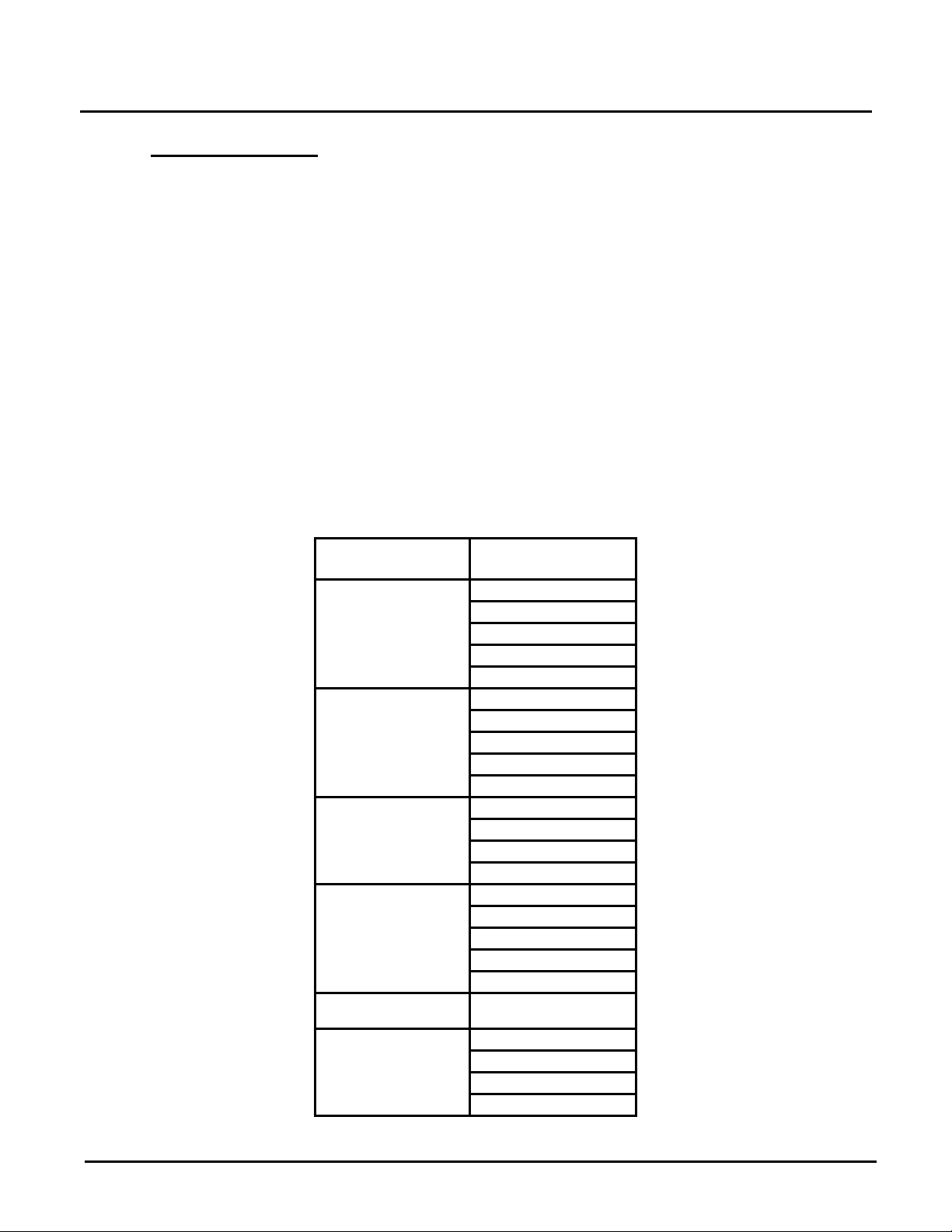
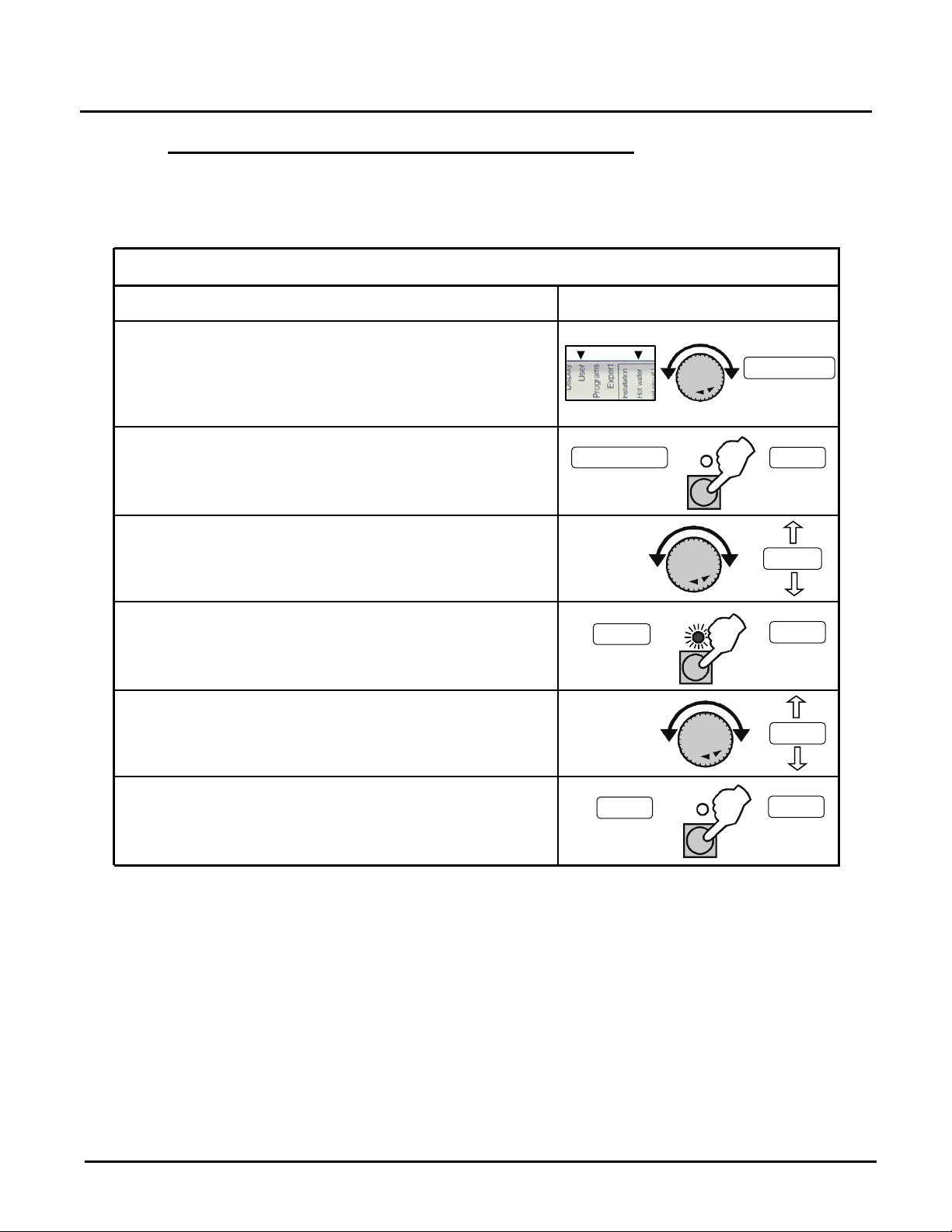
Parameter Change Procedure
Use Rotary Knob to navigate to desired Menu/Sub-
Press Program Key to access parameters in the
selected (displayed) sub-menu.
Turn Rotary Knob to sequence through the available
parameters.
To change a parameter value, press the Program Key
To change the displayed parameter value, turn Rotary
To save the displayed parameter value to the controller
will turn off indicating the new value has been saved.
-
-
T-DHW
displayed
sub-menu
displayed
values
accessed
displayed
value
Displayed
Example: User Menu & Hot Water Sub-menu
parameters
accessed
Cycle thru
cycle thru
push!
push!
push!
Display Detail
Description
Examples
Displayed
Sub-menu
3.2.2 Basic Parameter Navigation, Selection, and Revision
When in the USER, TIME PROGRAM, EXPERT, or GENERAL Main Menu, virtually all sub-
menu items can be changed if the desired. Perform the following steps to access, view, and/or
change menu item parameters:
menu. Menu and sub-menu are indicated by two small
black arrows at bottom of LCD display pointing down to
menu/sub-menu names below display (see Figure 3-
HOT
WATER
HOT-WATER
when desired parameter is displayed. The Change LED
will light up indicating the displayed parameter may now
be changed.
Knob; clockwise to increase value and counterclockwise to decrease the value.
memory, press the Program Key. The Change LED
parameters
T-DHW
parameter
values
142.0
DHW
T
140.0
141.0
142.0
Value Saved!
PR1: 11/30/12 Page 16 of 112
Page 17

GF-115-C
OMM-0084_0D
AERCO International, Inc. • 100 Oritani Dr. • Blauvelt, NY 10913 • Ph: 800-526- 0288
4. E8 CONTROLLER MENUS AND SUB-MENUS
This section provides flow-chart illustrations and tabular listings of all Menu and Sub-Menu functions.
Overall menu hierarchy is shown below:
1. DISPLAY
a. INSTALLATION
b. HOT WATER
c. HEAT CIRCUIT I
d. HEAT CIRCUIT II
e. SOLAR/MF
2. USER
a. INSTALLATION
b. HOT WATER
c. HEAT CIRCUIT I
d. HEAT CIRCUIT II
e. SOLAR/MF
3. TIME PROGRAMS
a. CIRCL TIME
b. HOTW-PROG
c. HTG-PROG 1
d. HTG-PROG 2
4. EXPERT
a. INSTALLATION
b. HOT WATER
c. HEAT CIRCUIT I
d. HEAT CIRCUIT II
e. SOLAR/MF
5. EXPERT HS
a. INSTALLATION
6. GENERAL
a. SERVICE
b. DATE/TIME
c. HOLIDAY
d. CLOCK CHANGE
IMPORTANT!
In the following flow-chart illustrations and tabular listings, descriptions, entry
ranges, and default values are provided for only the commonly used functions
which are referenced in Section 5, titled E8 Operating Mode: Set-Up &
Programming. These commonly used functions are shown in Bold Italics in
the illustrations and tables which follow. Refer to Section 8 for additional
information on functions marked “Not Applicable” in the illustrations and tables
provided.
PR1: 02/23/12 Page 17 of 112
Page 18
GF-115-C
Modulex E8 Controller and BCM
Operations and Maintenance Manual
OMM-0084_0D
DISPLAY
INSTALLATION
T-OUTSIDE
T-EXT DES
T-COLL DES
T-COLLECTOR
T-BOIL
T-SOLID FUEL
T-RETURN 1
T-RETURN 2
T-BUFFER T
T-BUFFER M
T-BUFFER L
T-STORAGE 3
MODGRAD
RETURN
HOT WATER
T-DHW RATED
T-DHW
T-DHW L
RETURN
HTG CIRCUIT 2
T-ROOM DES A
T-ROOM
HUMIDITY
T-FLOW RATED
T-FLOW
N-OPT-TIME
RETURN
SOLAR M/F
T-MF1
T-MF2
T-MF3
T-MF4
T-COLLECTOR
T-DHW
T-DHW L
RETURN
HTG CIRCUIT 1
T-ROOM DES A
T-ROOM
HUMIDITY
T-FLOW RATED
T-FLOW
N-OPT-TIME
RETURN
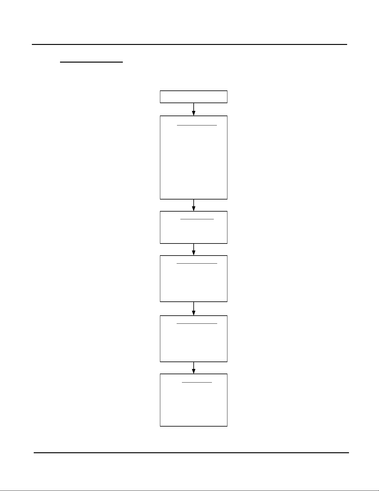
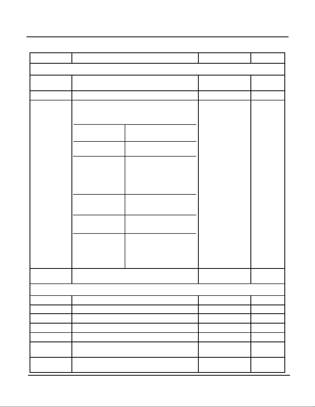
4.1 DISPLAY Menu
The DISPLAY Menu contains an INSTALLATION, HOT WATER, HEATING (HTG) CIRCUIT 1
& 2 and a SOLAR M/F Sub-Menu as shown in Figure 4-1 and in Table 4-1.
Figure 4-1: DISPLAY Menu Flow Chart
PR1: 11/30/12 Page 18 of 112
AERCO International, Inc. • 100 Oritani Dr. • Blauvelt, NY 10913 • Ph: 800-526- 0288
Page 19
GF-115-C
Modulex E8 Controller and BCM
Operations and Maintenance Manual
OMM-0084_0D
Boiler Set Point temperature in Indoor/ Outdoor
T-COLLECTOR
sequence between Heat Modules.
Knob to sequence between Heat Modules.
Sub-Menu.
Based on heating prog and
USER/HOT WATER menu.
T-DHW L
Not Applicable
T-CIRCL
Not Applicable
WATER Sub-Menu.
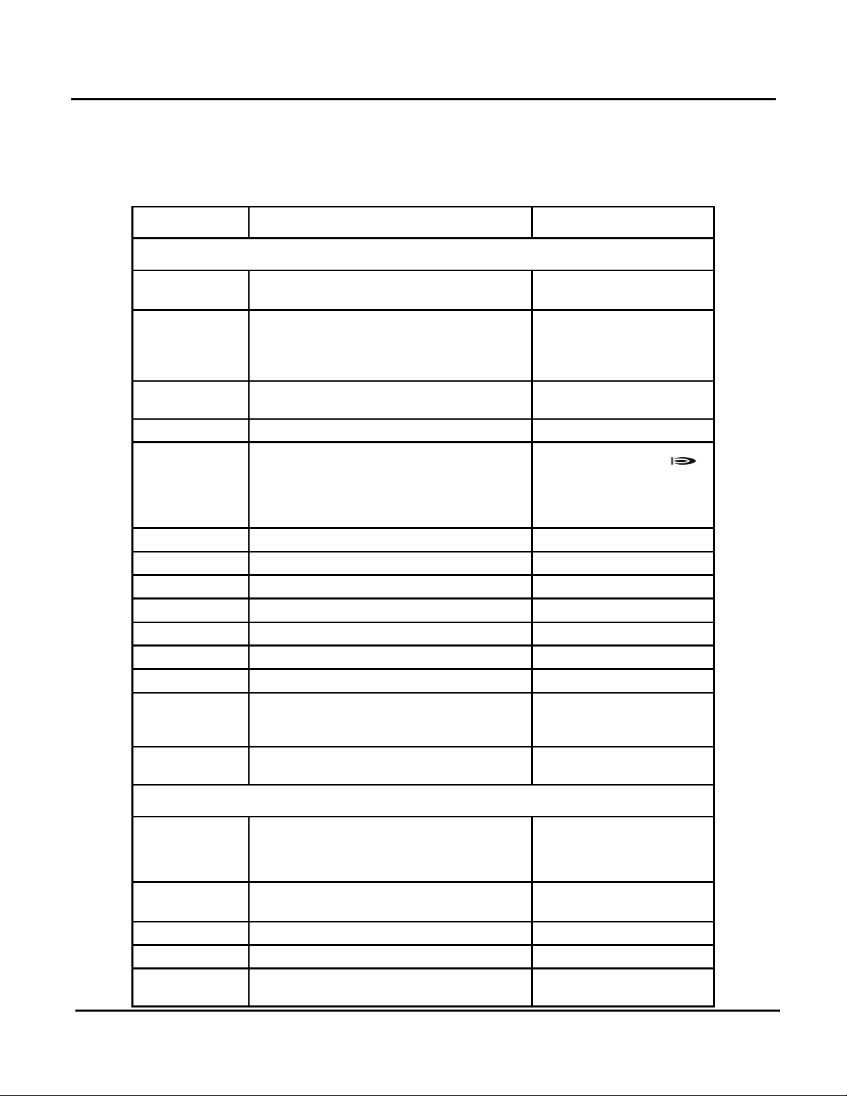
All DISPLAY Menu & Sub-Menu functions are READ ONLY and
cannot be changed. Temperature readings shown are in °F.
FUNCTION DESCRIPTION REMARKS
INSTALLATION Sub-Menu
NOTE
Table 4-1: DISPLAY Menu Listing
T-OUTSIDE Outside air temperature
T-EXT DES
T-COLL DES
T-BOIL
T-SOLID FUEL Not Applicable
T-RETURN 1 Not Applicable
T-RETURN 2 Not Applicable
T-BUFFER T Not Applicable
T-BUFFER M Not Applicable
T-BUFFER L Not Applicable
T-STORAGE 3 Not Applicable
MODGRAD
Boiler Set Point setting in 0 to 10 volt input
mode
Reset and Constant Set Point modes.
Header Set Point temperature (cascade)
Press Program Key to display temperature
and ON/OFF status of individual Heat
Modules (HS) which range from 2 (MLX-
303) to 7 (MLX-1060). Turn Rotary Knob to
Press Prog Key to display Modulation % for
individual Heat Modules (HS). Turn Rotary
Displayed only if outside
air sensor is installed.
A 0 to 10 volt external
input signal can be used to
change the Boiler set
point.
The Burner symbol ( )
is displayed when the
respective Heat Module is
ON.
RETURN
Press Program Key to exit INSTALLATION
HOT WATER Sub-Menu
T-DHW RATED
T-DHW Actual hot water temperature
RETURN
PR1: 11/30/12 Page 19 of 112
AERCO International, Inc. • 100 Oritani Dr. • Blauvelt, NY 10913 • Ph: 800-526- 0288
DHW set point temperature
Press Program Key to exit the HOT
operating mode. Actual
DHW set point as set in
Only if tank sensor is
installed
Page 20

GF-115-C
Modulex E8 Controller and BCM
Operations and Maintenance Manual
OMM-0084_0D
FUNCTION
DESCRIPTION
REMARKS
T-DHW
T-FLOW RATED
FLOW
N-OPT-TIME
Not Applicable
CIRCUIT 1 Sub-Menu.
T-MF3
Not Applicable
T-MF4
Not Applicable
1
T-DHW
Not Applicable
T-DHW L
Not Applicable
M/F Sub-Menu.
Table 4-1: DISPLAY Menu Listing (Continued)
HTG CIRCUIT 1 Sub-Menu
T-ROOM DES A Not Applicable
T-ROOM Current room air temperature.
HUMIDITY Room humidity (%).
T-DHW RATED Hot water set point temperature
Current hot water temperature
Current flow set point temperature
Current flow temperature
RETURN
HTG CIRCUIT 2 Sub-Menu
Functions for HTG (Heating) Circuit 2 are identical to HTG Circuit 1 Functions
above.
Press Program Key to exit HTG
Only if indoor sensor is
connected
Only if humidity sensor
is installed and
parameters set for
heating circuit.
Appears only if heating
circuit is programmed
as hot water circuit
Same as above
Not applicable
SOLAR M/F Sub-Menu
T-MF1
T-MF2
T-COLLECTOR
RETURN
PR1: 11/30/12 Page 20 of 112
AERCO International, Inc. • 100 Oritani Dr. • Blauvelt, NY 10913 • Ph: 800-526- 0288
Not Applicable
Not Applicable
Not Applicable
Press Program Key to exit SOLAR
Currently not used
Currently not used
Currently not used
Currently not used
Currently not used
Currently not used
Currently not used
Page 21
GF-115-C
Modulex E8 Controller and BCM
Operations and Maintenance Manual
OMM-0084_0D
USER
INSTALLATION
LANGUAGE
CONTRAST
DISPLAY SEL
RETURN
HOT WATER
1X DHW
T-DHW 1
T-DHW 2
T-DHW 3
BOB VALUE
CIRCL-P-DHW
ANTILEGION
RETURN
SOLAR M/F
RETURN
HTG CIRCUIT 1
MODE
T-ROOM DES 1
T-ROOM DES 2
T-ROOM DES 3
T-REDUCED
T-ABSENCE
T-LIMIT DAY
T-LIMIT N
HEATSLOPE
OPTIM HEAT
MAX OPT-TIME
ECONO OPTI
PC ENABLE
RETURN
HTG CIRCUIT 1
MODE
T-ROOM DES 1
T-ROOM DES 2
T-ROOM DES 3
T-REDUCED
T-ABSENCE
T-LIMIT DAY
T-LIMIT N
HEATSLOPE
OPTIM HEAT
MAX OPT-TIME
ECONO OPTI
PC ENABLE
RETURN
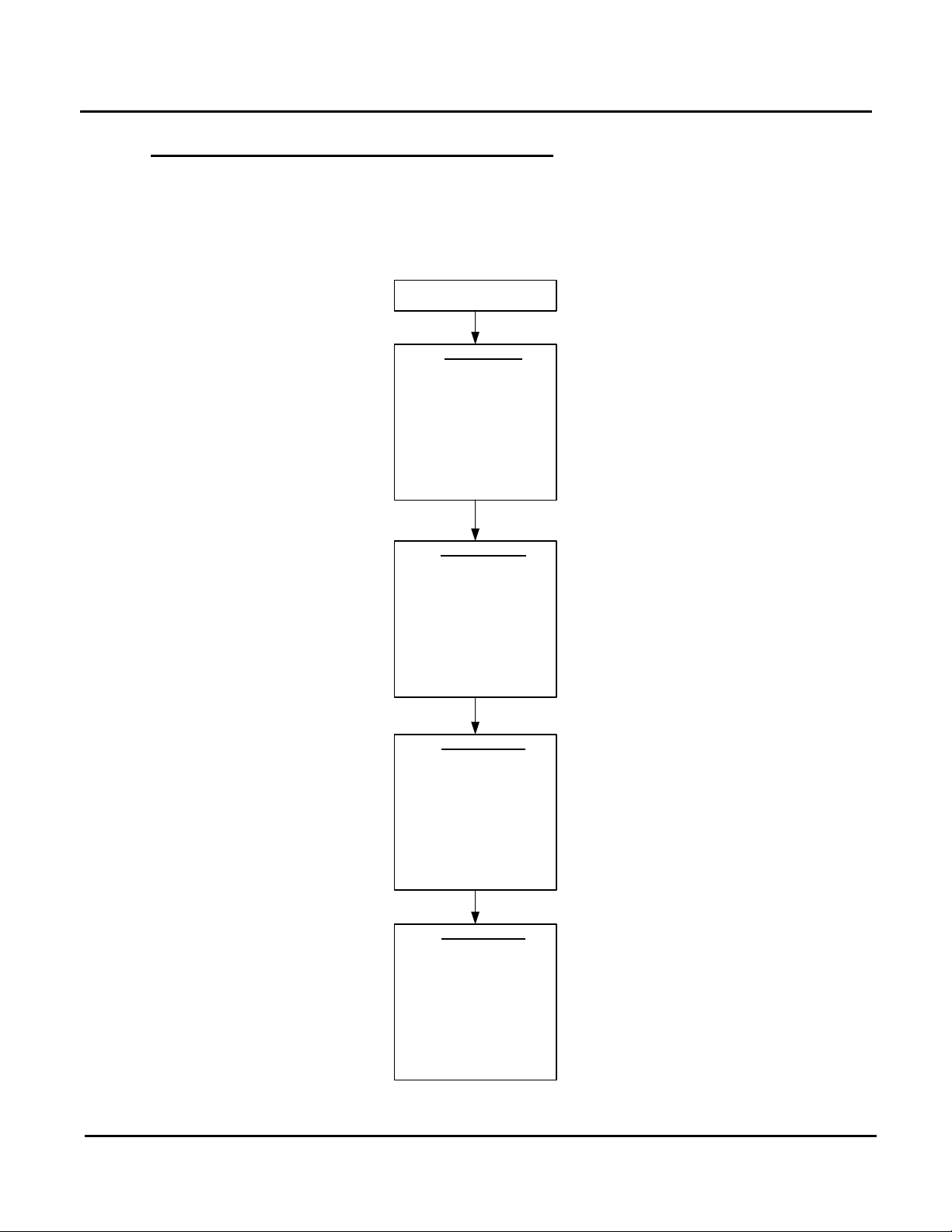
4.2 USER Menu
The USER Menu (Figure 4-2) contains the same Sub-Menus as the DISPLAY Menu.
However, the USER Menu items are not “Read Only” and therefore can be changed. The SubMenu functions in the USER Menu also differ from those contained in the DISPLAY Menu.
Tabular listings for the USER Menu items are provided in Table 4-2.
Figure 4-2: USER Menu Flow Chart
PR1: 11/30/12 Page 21 of 112
AERCO International, Inc. • 100 Oritani Dr. • Blauvelt, NY 10913 • Ph: 800-526- 0288
Page 22
GF-115-C
Modulex E8 Controller and BCM
Operations and Maintenance Manual
OMM-0084_0D
CONTRAST
00
Domestic Hot Water
connected).
Menu.
T-DHW 1
Hot Water set point
50°F - 158°F
140°F
T-DHW 2
Not Applicable
T-DHW 3
Not Applicable
DHW
Menu.
Table 4-2: USER Menu Listing
FUNCTION DESCRIPTION ENTRY RANGE DEFAULT
INSTALLATION Sub-Menu
LANGUAGE Selects display language.
Adjusts display contrast
Sets the day of the week or the sensor
temperature (°F) to appear in the display when
the swing-down panel is closed.
Day: SUN – SAT
T-OUTSIDE: Outside Temperature
FLOW TEMP (1/2): Flow Temp. For Heating
Circuit 1 or 2 supply
DISPLAY
SEL
water temperature. (Only
if sensor is installed)
T-DHW:
Temperature.
T-BOILER; Boiler Outlet Temperature.
T-ROOM (1 / 2): Room Temp, Heating
Circuit 1 or 2 (ONLY if
Remote Control is
12 languages are
available.
-20 to 20
ENGLISH
See
DESCRIPTION
Column
- - - -
RETURN
HOT WATER Sub-Menu
1X DHW Not Applicable
BOB-VALUE Not Applicable
CIRCL-P-
RETURN
PR1: 11/30/12 Page 22 of 112
Press Program Key to exit INSTALLATION Sub-
Not Applicable
Press Program Key exit HOT WATER Sub-
AERCO International, Inc. • 100 Oritani Dr. • Blauvelt, NY 10913 • Ph: 800-526- 0288
Page 23

GF-115-C
Modulex E8 Controller and BCM
Operations and Maintenance Manual
OMM-0084_0D
Night
T-ROOM DES 1
Not Applicable
T-ROOM DES 2
Not Applicable
T-REDUCED
Not Applicable
T-ABSENCE
Not Applicable
-23.0°F–104.0°F
periods.
-23.0°F–104.0°F
1°F.
OPTIM HEAT
Not Applicable
ECONO OPTI
Not Applicable
PC-ENABLE
Not Applicable
CIRCUIT 1 (or 2) sub-menu.
display to the TIME PROGRAM Menu.
Table 4-2: USER Menu Listing (Continued)
FUNCTION DESCRIPTION ENTRY RANGE DEFAULT
HTG CIRCUIT 1 Sub-Menu
- - - -, Standby,
MODE Displays Timer Mode for Boiler
Auto 1, Auto 2, Day,
- - - -
T-ROOM DES 3
T-LIMIT DAY Applies during day-time heating periods
T-LIMIT N
HEATSLOPE
MAX OPT-TIME
RETURN
HTG CIRCUIT 2 Sub-Menu
Functions for HTG Circuit 2 are identical to HTG Circuit 1 Functions listed above.
Not Applicable
Applies during reduced night-time
Indicate number of degrees that the flow
temperature changes if the outside
temperature increases or decreases by
Not Applicable
Press Program Key to exit HTG
- - - -,
- - - -,
0.00 – 3.00 1.20
66.0°F
50.0°F
SOLAR M / F Sub-Menu (No Functions Currently In This Sub-Menu)
Pressing the Program Key with SOLAR
M/F displayed will change display to
RETURN
PR1: 11/30/12 Page 23 of 112
AERCO International, Inc. • 100 Oritani Dr. • Blauvelt, NY 10913 • Ph: 800-526- 0288
RETURN. Press Program Key again to
redisplay SOLAR M/F. Turning the
Rotary Knob clockwise will advance thd
Page 24
GF-115-C
Modulex E8 Controller and BCM
Operations and Maintenance Manual
OMM-0084_0D
TIME PROGRAM
CIRCL TIME
MONDAY
TUESDAY
WEDNESDAY
THURSDAY
FRIDAY
SATURDAY
SUNDAY
MO-FR
SA-SU
MO-SU
RETURN
HOTW-PROG
MONDAY
TUESDAY
WEDNESDAY
THURSDAY
FRIDAY
SATURDAY
SUNDAY
MO-FR
SA-SU
MO-SU
RETURN
HTG-PROG 1
MONDAY
TUESDAY
WEDNESDAY
THURSDAY
FRIDAY
SATURDAY
SUNDAY
MO-FR
SA-SU
MO-SU
RETURN
HTG-PROG 2
MONDAY
TUESDAY
WEDNESDAY
THURSDAY
FRIDAY
SATURDAY
SUNDAY
MO-FR
SA-SU
MO-SU
RETURN
4.3 TIME PROGRAM Menu and Sun-Menus
Day and Time-related functions can be set using the TIME PROGRAM Menu and its
associated Sub-Menus. However, at the present time, none of the Sub-Menus and functions
in the TIME PROGRAM Menu are being utilized. This menu is shown in Figure 4-3.
Refer to Section 8 for additional information on these Menu and Sub-Menu functions.
Figure 4-3: TIME PROGRAM Menu Flow Chart
PR1: 11/30/12 Page 24 of 112
AERCO International, Inc. • 100 Oritani Dr. • Blauvelt, NY 10913 • Ph: 800-526- 0288
Page 25
GF-115-C
Modulex E8 Controller and BCM
Operations and Maintenance Manual
OMM-0084_0D
EXPERT
INSTALLATION
CODE-NO
BUS ID HS
BUS ID 1
BUS ID 2
AF SUPPLY
BUS TERM
EBUS SUPPLY
TIME MASTER
MAX T COLL
MIN T COLL
MAX T-HS2
MIN T-HS2
V-CURVE
CURVE 11-U1
CURVE 11-U2
CURVE 11-T1
CURVE 11-T2
CURVE 11-UA
HYSTERESIS
FOUND MODULS
CAP/MODULE
NEW CONFIG
MIN MOD CASC
HW-BOILER
CONTR DEVIAT
DES OUTPUT
BLOCK TIME
MAX T-MODUL
DYN UPWARD
DYN DOWNWARD
RESET TIME
MODULAT MAX
MODULAT MIN
MIN MOD HS
SEQUENCE 1
SEQUENCE 2
SEQU CHANGE
SEQ SW TIME
LOCK TIME
HYST BURNER 2
HS COOL FUNC
T-HS COOL
HEATSOURCE 1
HS1 BUS
HEATSOURCE 2
STORAGE HS 2
BUFFER
RETURN
CONTINUED ON SHEET 2
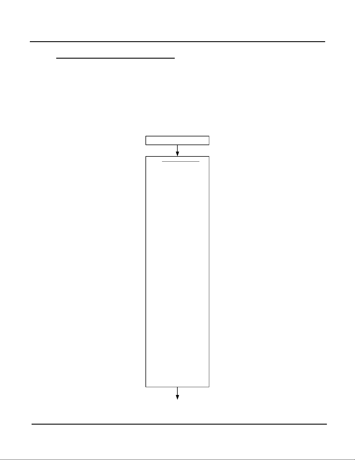
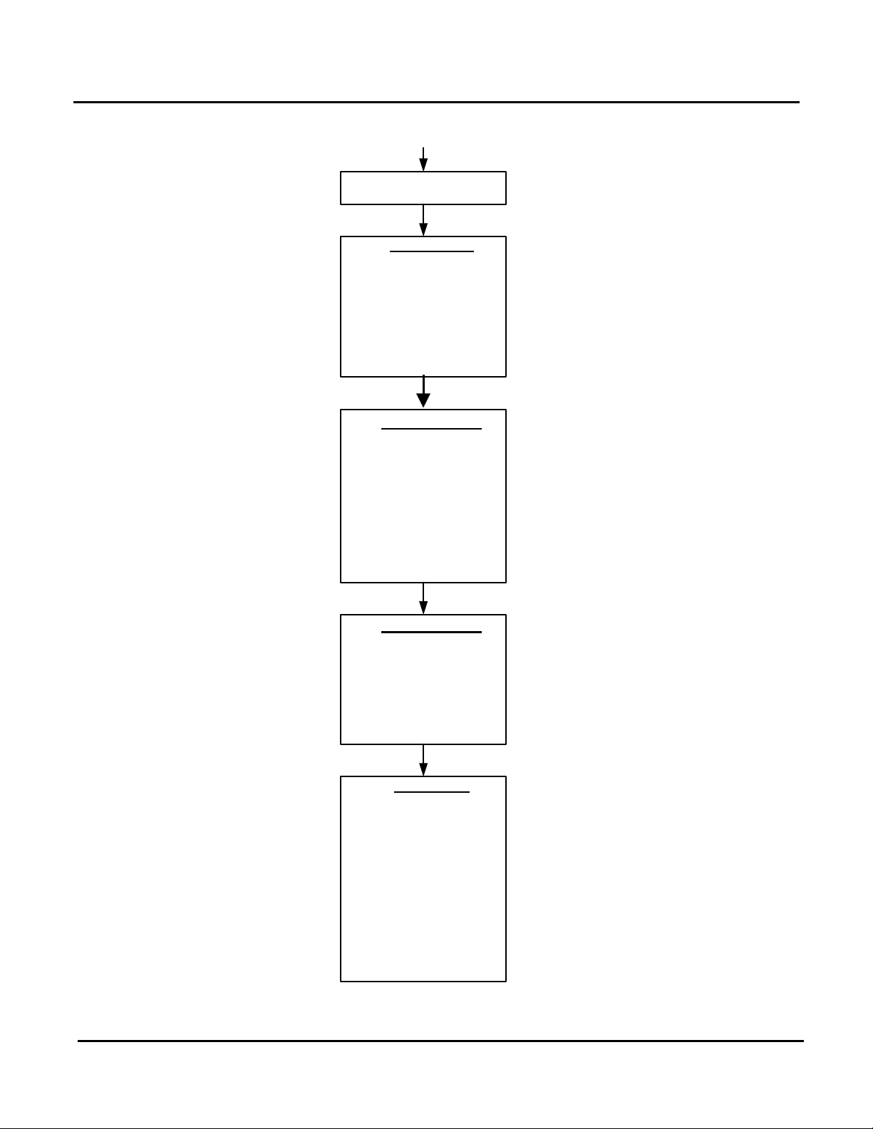
4.4 EXPERT Menu and Sub-Menus
The EXPERT Menu contains the following Sub-Menus: INSTALLATION, HOT WATER, HEAT
CIRCUIT 1, HEAT CIRCUIT 2 and SOLAR M/F as shown in Figure 4-4. As this figure shows,
the EXPERT Menu includes an extensive list of Sub-Menu functions, particularly in the
INSTALLATION Sub-Menu. Tabular listings for the EXPERT Menu and Sub-Menu items are
provided in Table 4-3.
Whenever “CODE NO.” is displayed, it indicates that the valid password must be entered. This
is accomplished by entering code 0000 (four zeros) by pressing the Program Key four (4)
times.
PR1: 11/30/12 Page 25 of 112
Figure 4-4: EXPERT Menu Flow Chart (Sheet 1 of 2)
AERCO International, Inc. • 100 Oritani Dr. • Blauvelt, NY 10913 • Ph: 800-526- 0288
Page 26
GF-115-C
Modulex E8 Controller and BCM
Operations and Maintenance Manual
OMM-0084_0D
EXPERT
HTG CIRCUIT 1
HC FUNCTION
PUMP MODE
MIXER OPEN
MIXER CLOSE
MAX T-FLOW
MIN T-FLOW
T-FROST PROT
OUT-TEMP-DEL
SLOPE OFFSET
B-HEAT SINK
RETURN
HOT-WATER
DHW RELIEF
PARALLEL
T-BOILER DHW
HYST DHW
DHW FOLLOWUP
THERM INPUT
WALL HUNG
LOAD THROUGH
RETURN
HTG CIRCUIT 2
HC FUNCTION
PUMP MODE
MAX T-FLOW
MIN T-FLOW
T-FROST PROT
OUT-TEMP-DEL
B-HEAT SINK
RETURN
SOLAR M/F
RELAY FUNC 1
T-MF 1 SETP
MF1 HYST
RELAY FUNC 2
T-MF 2 SETP
MF2 HYST
RELAY FUNC 3
T-MF 3 SETP
MF3 HYST
RELAY FUNC 4
T-MF 4 SETP
MF4 HYST
F15 FUNCTION
RETURN
CONTINUED FROM SHEET 1
Figure 4-4: EXPERT Menu Flow Chart (Sheet 2 of 2)
PR1: 11/30/12 Page 26 of 112
AERCO International, Inc. • 100 Oritani Dr. • Blauvelt, NY 10913 • Ph: 800-526- 0288
Page 27
GF-115-C
Modulex E8 Controller and BCM
Operations and Maintenance Manual
OMM-0084_0D
INSTALLATION Sub-Menu
CODE-NO
Permits entry of valid Code No.(0000)
0000 - 9999
0000
the boiler
CHANGE
numbers must not be assigned twice.
be assigned twice.
AF SUPPLY
Outdoor sensor power supply
00, 01 (OFF/ON)
01 (ON)
BUS TERM
Bus terminating resistor (Must be set to 01)
00, 01 (OFF/ON)
01 (ON)
SUPPLY
MASTER
point temperature.
temperature.
0 to 10 Volt input Voltage curves. Choose
customize a curve.
CURVE 11-U1
Low voltage setting
0.00V – 10.00V
0.000
CURVE 11-U2
High voltage setting
0.00V – 10.00V
10.00
CURVE 11-T1
Minimum set point temperature
32.0°F – 248.0°F
59.0°F
CURVE 11-T2
Maximum set point temperature
32.0°F – 248.0°F
185.0°F
this setting will stop/start the Boiler.
NOTE
Whenever “CODE NO.” is displayed, it indicates that the valid
password must be entered. This is accomplished by entering code
0000 (four zeros) by pressing the Program Key four (4) times.
Table 4-3: EXPERT Menu Listing
FUNCTION DESCRIPTION ENTRY RANGE DEFAULT
BUS ID HS
BUS ID 1
BUS ID 2
EBUS
TIME
MAX T-COLL
MIN T-COLL
MAX T-HS2
MIN T-HS2
BUS ID HS MUST be set to - - - - to operate
The heating circuits are sequentially
numbered starting with „01“, heating circuit
Heating circuits are sequentially numbered
starting with “01“, heating circuit numbers must not
Switches the Ebus supply ON/OFF 00, 01 (OFF/ON) 01 (ON)
Not Applicable
Sets the maximum allowable header set
Sets the minimum allowable header set point
Not Applicable
Not Applicable
01 - 08
(00), 01 – 15 01
(00), 01 – 15 - - - -
86.0°F – 230.0°F 185.0°F
50.0°F – 176.0°F 50.0°F
DO NOT
V-CURVE
CURVE 11-UO
from preset curves (see para. 3.5.1) or
Stop/Start voltage level. Going below/above
PR1: 11/30/12 Page 27 of 112
AERCO International, Inc. • 100 Oritani Dr. • Blauvelt, NY 10913 • Ph: 800-526- 0288
00 – 11 11
0.00V – 10.00V 1.00
Page 28

GF-115-C
Modulex E8 Controller and BCM
Operations and Maintenance Manual
OMM-0084_0D
(Continued)
HYSTERESIS
Not Applicable
–
MODULS
for service.
module.
NEW CONFIG
Not Applicable
CASC
HW-BOILER
Not Applicable
00 – 08
00
actual water temperature.
DES OUPUT
Required system output [in %]
0 – 100%
00
SWITCH TIME
Not Applicable
(N/A)––
(N/A)
BLOCK TIME
Not Applicable
(N/A)
(N/A)
MODUL
UPWARD
DOWNWARD
RESET TIME
Not Applicable
5 – 500
50
after the delay time elapses.
off
MIN MOD HS
Not Applicable
0% - 60%
35%
HW
SEQUENCE 1
SEQUENCE 2
Boiler sequence 2
87654321
Table 4-3: EXPERT Menu Listing (Continued)
FUNCTION DESCRIPTION ENTRY RANGE DEFAULT
INSTALLATION Sub-Menu
FOUND
CAP/MODULE
MIN MOD
CONTR
DEVIAT
MAX T-
DYN
DYN
Displays the number of heat modules available
Displays the maximum Kw output of each heat
Not Applicable 01 – 08 01
Control Deviation indicates the temperature
difference between the Boiler set point and the
Maximum temperature of Heat Module 122.0°F to 230.0°F 194.0°F
Not Applicable (N/A) (N/A)
Not Applicable (N/A) (N/A)
Display
00 – 1000 Kw 40 Kw
Display °F
MODULAT
MAX
MODULAT
MIN
MOD LEVEL
PR1: 11/30/12 Page 28 of 112
Start Level. If this modulation percentage is
exceeded, the next heat module is connected
Stop Level. If value drops below this
modulation percentage, the last heat generator
(module) of the current sequence is switched
Not Applicable
Boiler sequence 1 12345678
AERCO International, Inc. • 100 Oritani Dr. • Blauvelt, NY 10913 • Ph: 800-526- 0288
50% - 100% 30%
10% - 60% 35%
Page 29

GF-115-C
Modulex E8 Controller and BCM
Operations and Maintenance Manual
OMM-0084_0D
ENTRY
RANGE
SEQU CHANGE
Sequence change mode
01 – 06
06
SEQ SW TIME
Time to sequence change (hours)
10 – 800
200
LOCK TIME
Not Applicable
00 min – 30 min
00
HYST BURNER2
Not Applicable
–
T-HS COOL
Not Applicable
Identification of Boiler Type being used:
06 = Multi-Stage, modulating (cascade via BUS)
Heat Source
HEATSOURCE 2
Not Applicable
N/A–
N/A
STORAGE HS2
Not Applicable
N/A–
N/A
BUFFER
Not Applicable
N/A
N/A
SCREED
Not Applicable
N/A
N/A
SCREED PROGR
Not Applicable
N/A
N/A
RETURN
Press Program Key to exit INSTALLATION Sub-Menu.
HOT WATER Sub-Menu
DHW RELIEF
Not Applicable
N/A
N/A
02 = Pump Parallel Running
DHW)
HYST DHW
Hot Water Hysteresis
48°F – 129°F
48°F
min.
Storage Tank With Thermostat = 01
WALL HUNG
Not Applicable
LOAD THROUGH
Not Applicable
RETURN
Press Program Key to exit HOT WATER Sub-Menu.
Table 4-3: EXPERT Menu Listing (Continued)
FUNCTION DESCRIPTION
DEFAULT
INSTALLATION Sub-Menu (Continued)
HS COOL-FCT Not Applicable
00 = No Boiler
HEATSOURCE 1
HS 1 BUS
01 = Single-Stage, switching
02 = Single-Stage, modulating
03 = 2-Stage, switching
04 = 2 individual, switching
05 = Multi-Stage, switching
Communication connection between Controller and
See
DESCRIPTION
00 – 04 02
06
(Multi-Stage
Modulating)
Parallel pump operation.
PARALLEL
T-BOILER DHW
DHW FOLLOWUP Pump Run-Down Time
THERM INPUT
PR1: 11/30/12 Page 29 of 112
00 = Hot Water Priority
01 = Hot Water Partial Priority
Boiler temperature increase during Hot Water
operation.
Boiler Temp = (DHW Temp Setting) + (T-BOILER
Storage Tank With Sensor = 00
AERCO International, Inc. • 100 Oritani Dr. • Blauvelt, NY 10913 • Ph: 800-526- 0288
00, 01, 02
32°F – 194°F 97°F
00 min. – 30
00, 01
01
00 min.
00
Page 30
GF-115-C
Modulex E8 Controller and BCM
Operations and Maintenance Manual
OMM-0084_0D
ENTRY
RANGE
mixing valve.
Circulation pump mode control for
03 = Continuous pump operation
MIXER CLOSE
Maximum allowable water temperature
setting for the heating circuit.
Minimum allowable water temperature
setting for the heat circuit.
Specifies the minimum allowable outside
INSTALLATION Mode)
DEL
OFFSET
B-HEAT SINK
Not Applicable
N/A
N/A
Press Program Key to exit HEAT
CIRCUIT 1 (or 2) Sub-Menu.
Table 4-3: EXPERT Menu Listing (Continued)
FUNCTION DESCRIPTION
HEAT CIRCUIT 1 & 2 Sub-Menus
The Sub-Menu Functions for HEAT CIRCUIT 1 & HEAT CIRCUIT 2 are identical, except for
the MIXER OPEN & MIXER CLOSE Functions which apply only to HEAT CIRCUIT 1. The
Function values in this Sub-Menu level will change, depending on the Heat Circuit Function
(HC FUNCTION) selected.
Heat Circuit Function defines type of
circuit:
00 = Standard Heat Circuit
01 = Control to fixed flow temperature
HC FUNCTION
PUMP MODE
02 = Swimming pool control (HC 2
ONLY)
03 = Hot Water Circuit
04 = Return flow temp. Increase via
ON/OFF switching of pumps.
00 = Standard pump control
01 = Pump switching per heating limits
02 = Pump switching per heating program
00 – 04
00 – 03 00
DEFAULT
00
(Standard
Heat
Circuit)
MIXER OPEN
MAX T-FLOW
MIN T-FLOW
T-FROST PROT
OUT-TEMP-
SLOPE
RETURN
Not Applicable
Not Applicable
air temperature setting for the Frost
Protection Mode. If temperature drops
below this value, the system switches to
the Frost Protect Mode and the pumps
are switched ON.
(This Function should be set to 0°F in the
Not Applicable N/A N/A
Not Applicable N/A N/A
68°F – 230°F 176°F
50°F – 230°F 50°F
-5°F – 41°F 32°F
PR1: 11/30/12 Page 30 of 112
AERCO International, Inc. • 100 Oritani Dr. • Blauvelt, NY 10913 • Ph: 800-526- 0288
Page 31

GF-115-C
Modulex E8 Controller and BCM
Operations and Maintenance Manual
OMM-0084_0D
ENTRY
RANGE
SOLAR M/F Sub-Menu
FUNCTION
SET TEMP
HYST (1-4)
02 = Light sensor
Sub-Menu.
Table 4-3: EXPERT Menu Listing (Continued)
FUNCTION DESCRIPTION
MF (1-4)
MF (1-4)
MF (1-4)
F15 FUNCTION
RETURN
Not Applicable
Not Applicable
Not Applicable
F15 Function
00 = Room Sensor for Heating Circuit 2
01 = 0 – 10V iInput
Press Program Key to exit SOLAR M/F
00 -02 00
DEFAULT
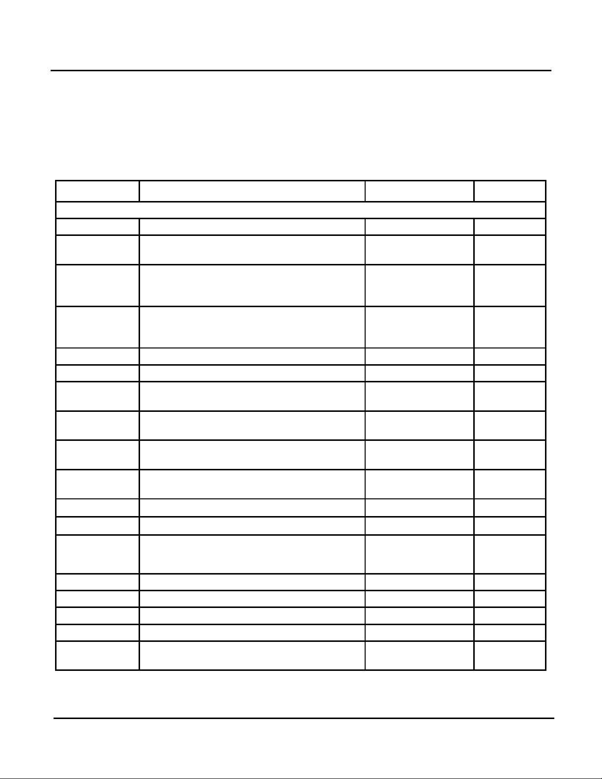
4.4.1 Available V-Curve Preset Voltage Curves for 0 – 10 Volt Input
The following listing (Table 4-4) shows the available preset V-Curve settings for operation in
the 0 to 10 Volt Mode:
Table 4-4: V-Curve Preset Voltage Curves for 0 – 10 Volt Input
CURVE NO. U1 U2 T1 T2 UO
0 2.0 V 10.0 V 32°F 194°F 2.0 V
1 2.5 V 0.3 V 100°F 176°F 5.0 V
2 2.5 V 0.3 V 100°F 167°F 5.0 V
3 2.5 V 0.3 V 100°F 113°F 5.0 V
4 4.0 V 0.1 V 68°F 185°F 5.0 V
5 4.0 V 0.1 V 68°F 167°F 5.0 V
6 4.0 V 0.1 V 68°F 131°F 5.0 V
7 4.0 V 0.1 V 68°F 189°F 5.0 V
8 4.0 V 0.1 V 68°F 189°F 5.0 V
9 4.0 V 0.1 V 68°F 163°F 5.0 V
10 4.0 V 0.1 V 68°F 127°F 5.0 V
11 4.0 V 0.1 V 68°F 194°F 5.0 V
PR1: 11/30/12 Page 31 of 112
AERCO International, Inc. • 100 Oritani Dr. • Blauvelt, NY 10913 • Ph: 800-526- 0288
Page 32

GF-115-C
Modulex E8 Controller and BCM
Operations and Maintenance Manual
OMM-0084_0D
DATE/TIME
HOLIDAY
YEAR START
MONTH START
DAY START
YEAR STOP
MONTH STOP
DAY STOP
TIME-DATE
TIME (MIN)
TIME (HOUR)
YEAR
MONTH
DAY
RETURN
CLOCK CHANGE
MONTH START
DAY START
MONTH STOP
DAY STOP
4.5 EXPERT HS Menu (Not Used)
(Not applicable to Modulex boilers)
4.6 GENERAL Menu
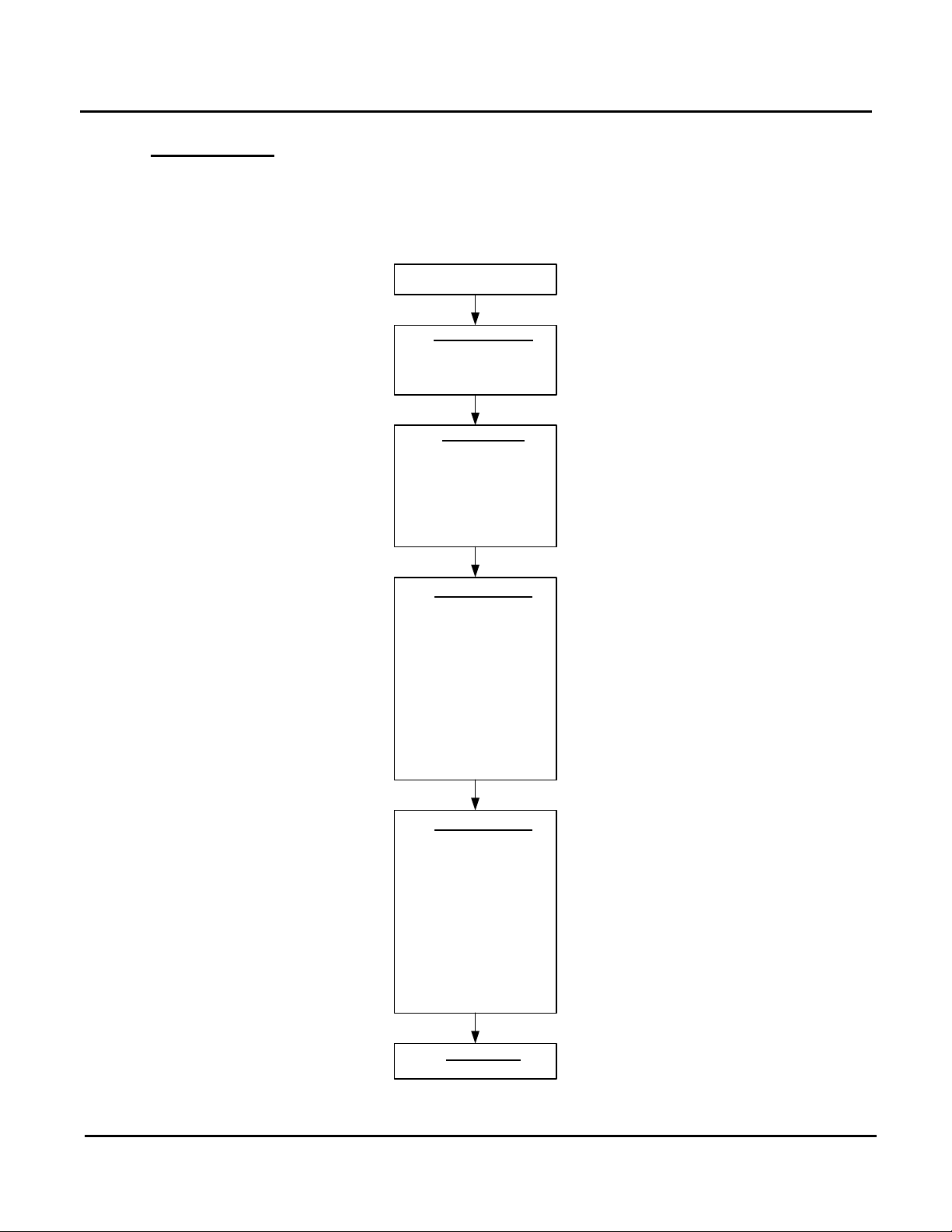
The GENERAL Menu contains a DATE/TIME Menu and a SERVICE Menu.
4.6.1 DATE / TIME Menu
This Sub-Menu is used to set the time, date, holiday (vacation) schedule and, where
necessary, enter clock change settings (daylight savings time, etc). The DATE/TIME menu
functions are illustrated and described in Figure 4-5 and Table 4-5.
PR1: 11/30/12 Page 32 of 112
Figure 4-5: DATE/TIME Menu Flow Chart
NOTE
All items in the following DATE/TIME Menu must be entered in sequence.
Press the Program Key to step through the menu functions. Use the Rotary
Knob to adjust/change entries. Press the Program Key to store entries and
sequence to the next function
AERCO International, Inc. • 100 Oritani Dr. • Blauvelt, NY 10913 • Ph: 800-526- 0288
Page 33

GF-115-C
Modulex E8 Controller and BCM
Operations and Maintenance Manual
OMM-0084_0D
TIME
Set current time (min., hours)
00:00 – 24:00
YEAR
Set current year
XXXX
MONTH
Set current month
01 – 12
DAY
Set currrent day
01 – 31
YEAR
Set current holiday start year
XXXX
START
DAY START
Set current holiday start day
01 – 31
YEAR STOP
Set current holiday end year
XXXX
STOP
DAY STOP
Set current holiday end day
01 – 31
START
DAY START
Set clock change start day
01 – 31
MONTH END
Set clock change end month
01 – 12
DAY END
Set clock change end day
01 – 31
Key.
Table 4-5: DATE / TIME Menu Listing
FUNCTION DESCRIPTION ENTRY RANGE
TIME – DATE Sub-Menu
This Sub-Menu is used to set the time, date, holiday schedule and, where necessary, enter
clock change settings (daylight savings time, etc).
HOLIDAY Sub-Menu
This Sub-Menu sets the start and end dates for Holiday (Vacation) periods where no heat or
hot water is required.
MONTH
MONTH
CLOCK CHANGE Sub-Menu
This Sub-Menu is used in areas where seasonal time changes are required for “Daylight
Savings“, etc.
MONTH
RETURN
Set current holiday start month 01 – 12
Set current holiday end month 01 – 12
Set clock change start month 01 -12
When CLOCK CHANGE reappears, press Program
PR1: 11/30/12 Page 33 of 112
AERCO International, Inc. • 100 Oritani Dr. • Blauvelt, NY 10913 • Ph: 800-526- 0288
Page 34

GF-115-C
Modulex E8 Controller and BCM
Operations and Maintenance Manual
OMM-0084_0D
SERVICE
SENSOR TEST
F1
F2
F3
F5
F6
F8
F9
F11
F12
F13
F14
RELAY TEST
CODE NO
01 - 11
SW NO 259-04
BURNER TIME
BURNER START
LIMITER TEST
SERVICE
RESET USER
RESET EXPERT
RESET PRG
RETURN
RETURN
CASCADE MANU
BOILER 01 – 00%
BOILER 02 – 00%
BOILER 03 – 00%
BOILER 04 – 00%
BOILER 05 – 00%
BOILER 06 – 00%
BOILER 07 – 00%
BOILER 08 – 00%
BOILER INT – 00%
RETURN
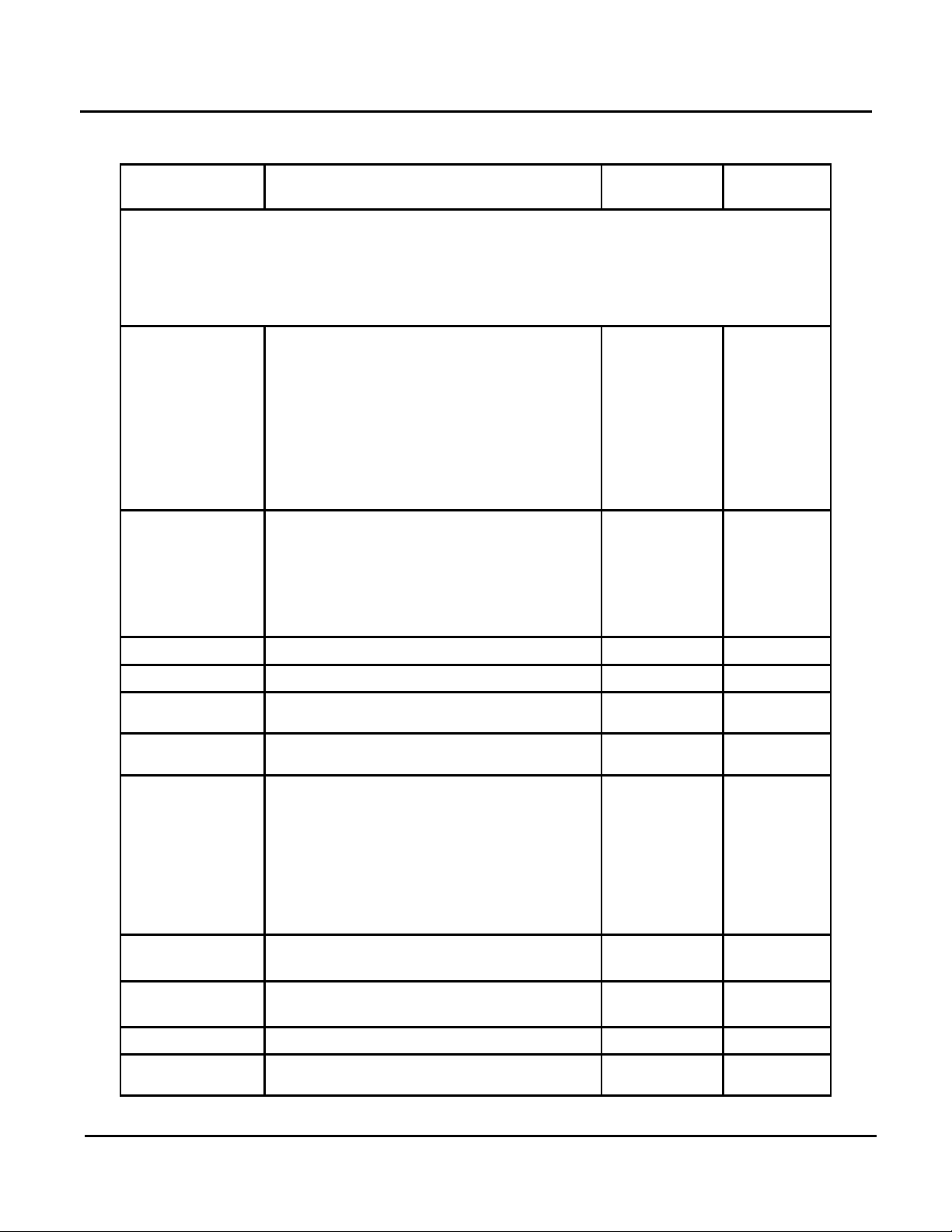
4.6.2 SERVICE Menu
The SERVICE Menu contains all the test and diagnostic functions/values required for
Customer Service Engineers to troubleshoot the equipment in a timely manner. The SERVICE
Menu items are illustrated and described in Figure 4-6 and Table 4-6 respectively.
Some of the functions in this Sub-Menu require a valid Code No. (password) to be entered,
prior to accessing/changing Function values. When prompted by a “CODE NO.” display, enter
0000 (four zeros) by pressing the Program Key four (4) times. This will allow function access.
Figure 4-6: SERVICE Menu Flow Chart
PR1: 11/30/12 Page 34 of 112
AERCO International, Inc. • 100 Oritani Dr. • Blauvelt, NY 10913 • Ph: 800-526- 0288
Page 35

GF-115-C
Modulex E8 Controller and BCM
Operations and Maintenance Manual
OMM-0084_0D
RELAY TEST Sub-Menu
No relay
A1: Pump, Heating Circuit 1
A3: Hot Water Charging Pump
A4: Mixer OPEN, Heating Circuit 2
A7: HS2 ON [2-stage:HS 1+2 (after 10s) ON]
Multifunction 1
Multifunction 2
A10: Multifunction 3
A11: Collector Pump / Multifunction 4
SENSOR
temperature heating circuit 1
Flow temperature, heating circuit 2
Flow temperature, heating circuit 2
Heat generator /header temperature
Outside temperature
Table 4-6: SERVICE Menu Listing
FUNCTION DESCRIPTION REMARKS
This Sub-Menu is used to check the status of the relays contained in the
Controlller. These relays are numbered 00 through 11 and are defined as shown
below. CODE NO. Entry is required to access these relays.
RELAY NO.
00
01
02
03
04
05
06
07
08
09
10
11
SENSOR TEST Sub-Menu
This Sub-Menu is used to check and display the temperature readings of the
sensors connected to the Controller.
F1
A2: Pump, Heating Circuit 2
A5: Mixer CLOSED, Heating Circuit 2
A6: HS 1 ON
A8: Mixer OPEN Heating Circuit 1 /
A9: Mixer CLOSED Heating Circuit 1 /
Buffer storage temperature Lower
F2
F3
F5
F5
F6
F8
F9
PR1: 11/30/12 Page 35 of 112
AERCO International, Inc. • 100 Oritani Dr. • Blauvelt, NY 10913 • Ph: 800-526- 0288
Buffer storage temperature middle or room
Upper buffer storage temperature
Upper hot water temperature
Page 36

GF-115-C
Modulex E8 Controller and BCM
Operations and Maintenance Manual
OMM-0084_0D
FUNCTION
DESCRIPTION
REMARKS
SENSOR TEST Sub-Menu
multifunction 1
multifunction 2
temperature multifunction 3
multifunction 4
input
currently installed in the Controller
menu functions.
8)
(1-8)
Start with Program Key (hold down)!
DO NOT USE
00
DO NOT USE
RETURN
Exit level using Program Key
Table 4-6: SERVICE Menu Listing (Continued)
F11
F12
F13
F14
F15; Light; 0-10V I
OTHER ENTRIES
Additional items and functions in the SERVICE Sub-Menu include the following:
SW NO XXX-XX
CASCADE MANU
(1-8)
BURNER TIME (1-
Flow temperature heating circuit 1 or temperature
Hot water temperature lower or temperature
Solid fuel boiler temperature or collector 2 or
Collector 1 temperature or temperature
Room temperature heating circuit 2 or measured
value of the light sensor or voltage value 0-10V
Specifies the Software Version and Index number
Starting different burner stages of the cascade
See GF-115-H, Section 7, Sub-section 7.5 for
additional startup instructions using these sub-
Program Key – Burner time for all stages
BURNER START
LIMITER TEST
(1-8)
SERVICE
Program Key – Burner start for all stages
Safety temperature limiter test with heat generator
temperature display
Input of date or operating hours for service
messages
WARNING: NEVER ATTEMPT TO USE THE FOLLOWING RESET FUNCTIONS.
RESET USER 00
RESET EXPERT
RESET T-PRG 00
PR1: 11/30/12 Page 36 of 112
AERCO International, Inc. • 100 Oritani Dr. • Blauvelt, NY 10913 • Ph: 800-526- 0288
DO NOT USE
Page 37

GF-115-C
Modulex E8 Controller and BCM
Operations and Maintenance Manual
OMM-0084_0D
4.7 E8 Controller Initial Startup
Initial startup of the Modulex Controller requires a number of one-time entries to be made in
the initial INSTALLATION Menu that appears in the display when the E8 controller door is first
opened. Table 4-7 on the next page lists the description, entry range, and default entry for all
parameter. Instructions for entry into this menu is shown below.
NOTE
All items in the INSTALLATION Menu must be entered in
sequence. Press the Program Key to step through the menu
functions. Use Rotary Knob to adjust/change entries. Press the
Program Key to store entries and sequence to the next menu
item.
Initial Startup INSTALLATION Entry
1. Set the POWER rocker switch, located to the right of the Controller, to the ON (1)
position.
2. Open the panel cover on the Controller. The LCD display will read INSTALLATION. All
values in this level must be entered, in sequence, without interruption. The initial entries
required include: LANGUAGE, TIME and DATE as shown in the INSTALLATION Table
at right.
3. The first function that appears is LANGUAGE. By default, the display should show
ENGLISH. If ENGLISH is not displayed, turn the Rotary Knob until ENGLISH appears.
4. Press the Program Key to store setting.
5. Next, TIME will be displayed. Enter the current time (minutes, hours) using the Rotary
Knob. Press the Program Key to store each value.
6. The next items displayed are the YEAR, MONTH and DAY. Enter each item using the
Rotary Knob and press the Program Key as previously described to store the entry.
7. Following entry of all LANGUAGE, TIME and DATE entries, continue entering the
remaining items shown in Figure 4-7 and Table 4-7 until all required items have been
entered. Use the Program Key and Rotary Knob to select, adjust and store all entries as
previously described.
8. Continue step 7 until RETURN appears in the display, indicating that you are at the end
of the INSTALLATION menu.
9. Press the Program Key to exit the INSTALLATION menu.
PR1: 11/30/12 Page 37 of 112
AERCO International, Inc. • 100 Oritani Dr. • Blauvelt, NY 10913 • Ph: 800-526- 0288
Page 38

GF-115-C
Modulex E8 Controller and BCM
Operations and Maintenance Manual
OMM-0084_0D
PARAMETERS
DESCRIPTION
DEFAULT
LANGUAGE
Set Language
ENGLISH
TIME
Set current time (min., hrs)
00:00 – 24:00
YEAR
Set current year
XXXX (4 digits)
MONTH
Set current month
00-12
DAY
Set current day of month
00-31
CONF DEVICE
Confirm Device
- - - -, 01 – 06
- - - -
HEATSOURCE 1
Heat Source 1
00 – 06
06
HS1 BUS
Heat Source 1 Bus
00 – 04
02
HEATSOURCE 2
Heat Source 2
00 – 05
00
STORAGE HS2
Storage Heat Source 2
00 – 03
00
BUFFER
Buffer
00, 01, 02
00
HC FUNCTION 1
Heating Circuit Function 1
00, 01, 03
00
HC FUNCTION 2
Heating Circuit Function 2
00 – 04
00
CAP/MODULE
See Paragraph 4.8.1 for instructions.
00 – 1000 Kw
40 Kw
4.8.2)
Setpoint
MF1 HYST
Multifunction Relay 1 Hysteresis
4°F – 18°F
9°F
4.8.2)
Setpoint
MF2 HYST
Multifunction Relay 2 Hysteresis
4°Ra – 18°Ra
9°F
RELAY FUNC 3
Relay Function 3
00 – 26
01
Setpoint
MF3 HYST
Multifunction Relay 3 Hysteresis
4°F – 18°F
9°F
RELAY FUNC 4
Relay Function 4
00 – 26
02
Setpoint
MF4 HYST
Multifunction Relay 4 Hysteresis
4°F – 18°F
9°F
BUS ID 1
Bus Identification No. 1
00 – 15
01
BUS ID 2
Bus Identification 2
00 – 15
02
5K SENSOR
5,000 Ohm Sensor
00=5K, 01=1K
00 = 5 K
Table 4-7: INSTALLATION Menu Listing
INSTALLATION Sub-Menu
ENTRY RANGE
RELAY FUNC 1
T-MF1 SETP Temperature – Multifunction Relay 1
RELAY FUNC 2
T-MF2 SETP Temperature – Multifunction Relay 2
T-MF3 SETP Temperature – Multifunction Relay 3
T-MF4 SETP Temperature – Multifunction Relay 4
Relay Function 1 (See Paragraph
Relay Function 2 (See Paragraph
00 – 26 00
86°F – 194°F 86°F
00 – 26 00
86°F – 194°F 86°F
86°F – 194°F 86°F
86°F – 194°F 86°F
PR1: 11/30/12 Page 38 of 112
AERCO International, Inc. • 100 Oritani Dr. • Blauvelt, NY 10913 • Ph: 800-526- 0288
Page 39

GF-115-C
Modulex E8 Controller and BCM
Operations and Maintenance Manual
OMM-0084_0D
4.7.1 CAP/MODULE Function (Maximum Kilowatts per Burner)
When the Program Key is pressed with CAP/MODULE displayed, the display may show
“SCAN”, indicating that the Controller is searching for related MODULE (BOILER) functions.
Once the scan is complete, follow instructions below.
CAP/MODULE Function (Setting Max. Kw per Burner)
1. Press the Program Key. The display will show CODE NO., requesting the valid code to be
entered.
2. Enter code 0000 (four zeros) by pressing the Program Key four times. The red LED will
remain lit while the four code digits are entered.
3. Press the Program Key
4. The display will show BOILER 1 (meaning Heat Module 1), along with kilowatt (Kw) setting
for the first Module. The default setting for each Boiler Module is 40 Kw.
NOTE
The 40 Kw setting is only a control parameter. It does not
represent the maximum input of each module.
5. If the desired Kw setting is not displayed, press the Program Key and change the setting
using the Rotary Knob. Once the desired setting is displayed, press the Program Key to
store the value.
6. Continue scrolling through each BOILER (Heat Module) and observe the Kw setting for
each one. Change as needed by repeating step 5.
7. Once all BOILER modules have been set, RETURN will be displayed.
8. Press the Program Key to continue with the next menu function (RELAY FUNC 1) in the
INSTALLATION Menu Table.
PR1: 11/30/12 Page 39 of 112
AERCO International, Inc. • 100 Oritani Dr. • Blauvelt, NY 10913 • Ph: 800-526- 0288
Page 40

GF-115-C
Modulex E8 Controller and BCM
Operations and Maintenance Manual
OMM-0084_0D
FUNCTION
DESCRIPTION
01
Header Pump
03
Booster Pump
06
Pump HS2
21
Pulsed Circulation Pump
23
Solar Integration
25
Return Flow Temperature Increase HS2
4.7.1 Available Settings for Relay Functions 1 – 4
Table 4-8 lists the available Function selections for Multi-Function (MF) Relays 1 thru 4:
Table 4-8: Relay 1-4 Functions
00 No MF Relay Function
02 Circulation (Time)
05 Pump HS1
20 Temperature-Controlled Circulation Pump
22 Solid Fuel Boiler Integration (Not Applicable)
24 Return Flow Temperature Increase HS1
26 Return Flow Temperature Increase Via Buffer Storage
PR1: 11/30/12 Page 40 of 112
AERCO International, Inc. • 100 Oritani Dr. • Blauvelt, NY 10913 • Ph: 800-526- 0288
Page 41

GF-115-C
OMM-0084_0D
AERCO International, Inc. • 100 Oritani Dr. • Blauvelt, NY 10913 • Ph: 800-526- 0288
5. E8 OPERATING MODE: Set-up and Programming
The following paragraphs provide the detailed set-up and programming procedures necessary
to configure the Modulex Boiler for service operation.
NOTE
When performing the following operating mode set-up procedures,
refer to Section 3 of this document for illustrations and
descriptions of the Controller operating controls and displays.
Refer to Section 6 for Controller wiring connections.
5.1 Indoor/Outdoor Reset Mode
This mode is used to adjust the boiler set point based on the outdoor air temperature and a
programmed heating curve. The heating curve can be customized using functions provided in
the USER menu. The outdoor air sensor provided with the Modulex boiler must be installed to
enable this mode of operation. The following paragraphs provide the procedures necessary to
wire and configure the controller for operation in the Indoor/Outdoor Reset mode.
5.1.1 Wiring Connections
The outdoor air sensor provided with the boiler should be mounted on the outer North or
North-East side of the building away from windows, doors and vents. Never mount the outdoor
air sensor in a location where it is exposed to direct sunlight.
Wire the sensor using shielded 2-conductor, 18 AWG wire (Belden #8760, or equiv.). Connect
the outdoor air sensor wire leads to terminals 9 (F9) and 10 (GND) of Connector 1 on the rear
of the Controller. There is no polarity to observe when connecting the wire leads. Refer to the
wiring diagrams in Section 6 for the locations of sensor connections. This sensor must be
connected prior to configuring the Controller (Paragraph 5.1.2).\
5.1.2 Indoor/Outdoor Reset Operation Configuration
The Indoor/Outdoor Reset Mode is configured using the USER menu as shown in instructions
on the next page.
IMPORTANT
The outdoor air sensor MUST be connected as described in
paragraph 5.1.1 above, prior to configuring the Controller for
Indoor/Outdoor Reset Mode operation.
PR1: 02/23/12 Page 41 of 112
Page 42

GF-115-C
Modulex E8 Controller and BCM
Operations and Maintenance Manual
OMM-0084_0D
60
70
80
90
100
110
120
130
140
150
160
170
180
190
200
210
220
0510152025303540455055606570
Outside Temperature ( F )
Flow Temperature ( F )
Indoor/Outdoor Reset Configuration in USER Menu
1. Ensure ON/OFF switch on front of Modulex boiler is in the ON position.
2. Open controller front panel.
3. Turn the Rotary Knob clockwise to the USER menu. The first sub-menu displayed will be
INSTALLATION.
4. Continue scrolling clockwise through the USER menu until the HTG CIRCUIT 1 sub-menu
is displayed.
5. With HTG CIRCUIT 1 displayed, press Program Key to enter sub-menu.
6. Use Rotary Knob to scroll to the HEATSLOPE sub-menu item. The display will show
“HEATSLOPE” and the current value stored in memory (0.00 to 3.00).
7. To change the HEATSLOPE value, press the Program Key. The red LED will light.
8. Refer to Heat Slope Diagram (Figure 5-1) to determine the required value for the
HEATSLOPE function based on the boiler installation design set point. The value entered
must be between 0 and 3.00.
9. Turn Rotary Knob until the desired HEATSLOPE value is displayed.
10. Press the Program Key to store the HEATSLOPE value.
11. Continue scrolling through the HTG CIRCUIT 1 sub-menu until RETURN is displayed.
PR1: 11/30/12 Page 42 of 112
Press the Program Key to exit the HTG CIRCUIT 1 sub-menu.
Figure 5-1: Heat Slope Diagram
AERCO International, Inc. • 100 Oritani Dr. • Blauvelt, NY 10913 • Ph: 800-526- 0288
Page 43

GF-115-C
Modulex E8 Controller and BCM
Operations and Maintenance Manual
OMM-0084_0D
5.1.3 Viewing the Boiler Setpoint
The setpoint temperature setting is viewed in the E8 controller display as shown below.
Viewing the Boiler Setpoint
1. Turn the Rotary Knob to the DISPLAY menu. The first sub-menu displayed will be
INSTALLATION.
2. Press the Program Key to enter the INSTALLATION sub-menu.
3. Turn Rotary Knob clockwise until T-COLL DES is displayed along with corresponding
temperature reading. This T-COLL DES reading equals the boiler set point.
5.2 Constant Set Point Mode
When a fixed header temperature is desired, configure the the Constant Set Point Mode as
shown in the instructions below.
Constant Setpoint Mode Configuration
1. Set the ON/OFF switch on the front of the Modulex boiler to the ON position.
2. Open the Controller front panel.
3. Turn the Rotary Knob clockwise to the EXPERT menu. The first item (sub-menu) displayed
will be INSTALLATION.
4. Continue turning the Rotary Knob clockwise until HEAT CIRCUIT 1 is displayed.
5. Press the Program Key to enter the HEAT CIRCUIT 1 sub-menu.
6. Scroll to HC FUNCTION. The currently stored setting (00 or 01) will be displayed. Normally,
00 will be displayed since this is the Factory Default. However, for the Constant Set Point
Mode, the HC FUNCTION setting must be changed to 01. If the HC FUNCTION is currently
set to 00, proceed to step 7. However, if it is set to 01, skip to step 11.
7. If the HC FUNCTION is set to 00, press the Program Key. CODE NO. will be displayed
requesting the valid code to be entered.
8. Enter code 0000 (four zeros) by pressing the Program Key four times. The red LED will
remain lit while the digits are entered.
9. With HC FUNCTION again displayed, press the Program Key. The red LED will light. Turn
the Rotary Knob to change the HC FUNCTION to 01.
10. Press the Program Key to store the 01 setting for the HC FUNCTION. Red LED will go off.
RESET will be momentarily displayed, followed by display of the current Controller software
version (e.g. SW 259-04). Following RESET, the Controller display will then switch to the
initial INSTALLATION menu.
11. Use Rotary Knob to scroll to the USER menu and access HTG CIRCUIT 1 sub-menu. Press
Program Key to enter the sub-menu.
12. Using Rotary Knob, scroll to T – FLOW DAY. The currently stored value for T – FLOW DAY
will be displayed. This represents the current Constant Set Point temperature in °F.
13. To change Constant Set Point value, press the Program Key and turn the Rotary Knob to
select the desired Constant Set Point. Press the Program Key again to store the Set Point.
PR1: 11/30/12 Page 43 of 112
AERCO International, Inc. • 100 Oritani Dr. • Blauvelt, NY 10913 • Ph: 800-526- 0288
Page 44

GF-115-C
Modulex E8 Controller and BCM
Operations and Maintenance Manual
OMM-0084_0D
MAX T-FLOW
MIN T-FLOW
The minimum allowable outlet water temperature
5.2.1 Wiring Connections
There are NO wiring connections required for this mode.
5.2.2 Constant Setpoint Mode Configuration
The Constant Setpoint Mode is enabled using functions contained in the EXPERT menu and
USER menu as shown on previous page.
5.2.3 Viewing Constant Set Point
The set point is viewed in the DISPLAY menu as shown below.
Viewing the Constant Setpoint
1. Use Rotary Knob to navigate to the DISPLAY menu. First sub-menu displayed will be
INSTALLATION.
2. Press the Program Key to enter the INSTALLATION sub-menu.
Turn Rotary Knob clockwise until T-COLL DES is displayed along with corresponding
temperature reading. This T-COLL DES reading equals the boiler set point in °F.
5.2.4 Configuring Set Point High and Low Limits Per Outside Temperature
Sensor
It is often desirable to control the maximum and minimum outlet water temperature based on
outside air temperature. For instance it might be desirable to set the outlet water temperature to
be 180º F whenever the outside temperature is 15º F or below, and 120º F whenever the
outside temperature is 60º F or higher. Four parameters must be set in the E8 Controller to
accomplish this. They are: HEATSLOPE, MAX T-FLOW, MIN T-FLOW, and MAX T-COLL.
Descriptions are provided in Table 5-1.
Table 5-1: E8 Controller Outside Temperature Sensor Parameters
Parameter Description
HEATSLOPE
MAX T-COLL
To select the best HEATSLOPE value to enter into the E8 Controller, consider the set of heat
slope curves shown in Figure 5-1. Locate the two points given by the coordinate pairs (Outside
Temperature, Flow Temperature); One for the low temperature range and one for the high
temperature range. Now find the curve that best fits these two points. Do not expect any single
curve to go through either point, let alone both points. Simply pick the best fit.
PR1: 11/30/12 Page 44 of 112
AERCO International, Inc. • 100 Oritani Dr. • Blauvelt, NY 10913 • Ph: 800-526- 0288
A curve that relates a boiler’s outflow temperature with the outside air
temperature monitored with a temperature sensor
The maximum allowable outlet water temperature
The maximum allowable outflow water collection manifold surface
temperature
Page 45

GF-115-C
Modulex E8 Controller and BCM
Operations and Maintenance Manual
OMM-0084_0D
5.2.4.1 Configuring HEATSLOPE Parameter
The HEATSLOPE value is configured as shown in the instructions below.
Configuring HEATSLOPE Parameter
1. Ensure ON/OFF switch on front of Modulex boiler is in the ON position.
2. Open controller front panel.
3. Turn the Rotary Knob clockwise to the USER menu.
4. Press Program Key to select the User submenu. The first item (sub-menu) displayed will
be INSTALLATION.
5. Continue scrolling clockwise through the USER menu until the HTG CIRCUIT 1 sub-menu
is displayed.
6. With HTG CIRCUIT 1 displayed, press the Program Key to enter this sub-menu.
7. Using the Rotary Knob, scroll to the HEATSLOPE variable. The display will show
“HEATSLOPE” and the current value stored in memory (0.00 to 3.00).
8. If the desired value for HEATSLOPE is not displayed, press the Program Key once. The
red LED will light.
9. Determine the required value for the HEATSLOPE function as explained above. The
value to be entered must be between 0 and 3.00 inclusively.
10. Turn the Rotary Knob until the desired HEATSLOPE value is displayed.
11. Press the Program Key to store the HEATSLOPE value. The value will flash indicating it
was entered.
Continue scrolling through the HTG CIRCUIT 1 sub-menu until RETURN is displayed.
Press the Program Key to exit the HTG CIRCUIT 1 sub-menu.
PR1: 11/30/12 Page 45 of 112
AERCO International, Inc. • 100 Oritani Dr. • Blauvelt, NY 10913 • Ph: 800-526- 0288
Page 46

GF-115-C
Modulex E8 Controller and BCM
Operations and Maintenance Manual
OMM-0084_0D
5.2.4.2 Configuring MAX T-FLOW and MIN T-FLOW Parameters
To enter the MAX T-FLOW and MIN T-FLOW values, see instructions below.
Configuring MAX T-FLOW and MIN T-FLOW Parameters
1. Ensure ON/OFF switch on front of Modulex boiler is in the ON position.
2. Open controller front panel.
3. Turn the Rotary Knob clockwise to the EXPERT menu. The first item (sub-menu) displayed
will be INSTALLATION.
4. Continue scrolling clockwise through the EXPERT menu until the HTG CIRCUIT 1 submenu is displayed.
5. With HTG CIRCUIT 1 displayed, press the Program key to enter the sub-menu.
6. Use Rotary Knob to scroll to MAX T-FLOW sub-menu. The display will show “MAX T-
FLOW” and the current value stored in memory (68 to 230).
7. To change MAX T-FLOW value, press the Program Key 6 times to sequence through the 4
digits and back to the current value for MAX T-FLOW.
8. Press the Program Key one more time. The red LED will light.
9. Rotate the Rotary Knob until the desired value for MAX T-FLOW is displayed.
10. Press the Program Key once. The new value for MAX T-FLOW will flash indicating it was
entered.
11. Turn the Rotary Knob to the next parameter displayed, MIN T-FLOW.
12. Press the Program Key once. The red LED will light.
13. Now turn Rotary Knob until desired MIN T-FLOW (50 – 230) value is displayed.
14. Press the Program Key once. The new value for MIN T-FLOW will flash indicating it was
entered.
Continue scrolling through the HTG CIRCUIT 1 sub-menu until RETURN is displayed. Press the Program Key to exit the HTG CIRCUIT 1 sub-menu.
PR1: 11/30/12 Page 46 of 112
AERCO International, Inc. • 100 Oritani Dr. • Blauvelt, NY 10913 • Ph: 800-526- 0288
Page 47

GF-115-C
Modulex E8 Controller and BCM
Operations and Maintenance Manual
OMM-0084_0D
5.2.4.3 Configuring MAX T-COL Parameter
To enter the MAX T-COL value, see instructions below.
Configuring MAX T-COLL Parameter
1. Set the ON/OFF switch on the front of the Modulex boiler to the ON position.
2. Open the swing-down hinged panel of the Controller.
3. Turn the Rotary Knob clockwise to the EXPERT menu. The first item (sub-menu) displayed
will be INSTALLATION.
4. The first sub-menu to be displayed will be INSTALLATION.
5. Press the Program key once to enter this sub-menu.
6. Using the Rotary Knob, scroll to MAX T-COLL. The display will show “MAX T-COLL” and
the current value stored in memory (86 to 230).
7. If the desired value for MAX T-FLOW is not displayed, press the Program Key 6 times to go
through the digit sequence.
8. Now press the Program key one more time. The red LED will light.
9. Rotate the Rotary Knob until the desired value for MAX T-COLL is displayed.
10. Press the Program Key once. The new value for MAX T-COLL will flash indicating it was
entered.
11. Continue scrolling through the INSTALLATION sub-menu until RETURN is displayed. Press
the Program Key to exit the INSTALLATION sub-menu.
5.3 0 to 10 Volt Remote Set Point Mode
This mode allows the boiler set point to be controlled by an external control signal. The following
paragraphs provide the procedures necessary to wire, configure and set the required functions
necessary to operate in the 0 to 10 volt remote set point mode.
5.3.1 Remote Signal Source Wiring Connections
When setting up to operate in the 0 to 10 volt remote set-point mode, the remote signal source
must be wired to terminals 1 (F-15) and 2 (GND) of connector number 3 (III) on the rear of the
Controller. See Section 6 for illustrations and pin-outs of the connectors located on the rear of
the Controller.
PR1: 11/30/12 Page 47 of 112
AERCO International, Inc. • 100 Oritani Dr. • Blauvelt, NY 10913 • Ph: 800-526- 0288
Page 48

GF-115-C
Modulex E8 Controller and BCM
Operations and Maintenance Manual
OMM-0084_0D
5.3.2 Configuring Remote Signal Source
Configure the Remote Signal Source as shown in the instructions below.
Configuring Remote Signal Source
1. Ensure ON/OFF switch on front of Modulex boiler is in the ON position.
2. Open Controller front panel.
3. Turn Rotary Knob clockwise to EXPERT menu. The first sub-menu displayed will be
INSTALLATION (sub-menu items scroll in this sequence: INSTALLATION, HOT
WATER, HEAT CIRCUIT 1, HEAT CIRCUIT 2, SOLAR / MF). Continue scrolling
(clockwise) through the EXPERT menu until SOLAR / MF is displayed.
4. With SOLAR / MF displayed, press the Program Key to enter the SOLAR / MF sub-menu.
5. Scroll through the SOLAR / MF sub-menu by turning Rotary Knob clockwise until the F-15
FUNCTION is displayed along with it’s presently stored value (default is 00).
6. Press Program Key to change the F-15 FUNCTION. Display will show CODE NO.,
requesting valid code to be entered.
7. Enter code 0000 (four zeros) by pressing the Program Key four times. The red LED will
remain lit while the four code digits are entered.
8. With F-15 FUNCTION displayed again and red LED lit, turn Rotary Knob to change the F-
15 FUNCTION to 01.
9. Press the Program Key to store the 01 setting for the F-15 FUNCTION. The red LED will
go off.
10. Continue scrolling through the sub-menu until RETURN is displayed.
11. Press the Program Key to exit the SOLAR / MF sub-menu.
12. With SOLAR / MF displayed, turn Rotary Knob counter-clockwise until the
INSTALLATION sub-menu is displayed in the LCD.
13. With INSTALLATION displayed in the LCD, proceed directly to paragraph 5.3.3.
NOTE
When navigating the menus during configuration and you scroll
past the SOLAR / MF item, the EXPERT HS menu will be
displayed. If this occurs, slowly turn the Rotary Knob
counterclockwise until SOLAR / MF is again displayed.
PR1: 11/30/12 Page 48 of 112
AERCO International, Inc. • 100 Oritani Dr. • Blauvelt, NY 10913 • Ph: 800-526- 0288
Page 49

GF-115-C
Modulex E8 Controller and BCM
Operations and Maintenance Manual
OMM-0084_0D
5.3.3 Setting the Voltage and Set Point Limits for U1/U2 and T1/T2
NOTE
Ensure that steps 1 through 13 in Paragraph 5.3.2 were
completed prior to performing the following steps.
NOTE
When scrolling through sub-menus and functions, enter required
Code 0000 only when prompted to do so. Normally, Code 0000
only needs to be entered once, unless you exit and re-enter
EXPERT menu.
U1 and U2 settings: To set the voltage limits corresponding to the minimum and maximum
allowable set point limits, follow the instructions below.
Voltage & Set Point Limits: U1 & U2
1. Press the Program Key to enter the EXPERT menu – INSTALLATION sub-menu. The
display will show CODE NO. requesting the valid code to be entered.
2. Enter code 0000 (4 zeros) by pressing the Program Key four times. The red LED will
remain lit while the four code digits are entered. A dashed line will appear in the display
following code entry.
3. Next, turn the Rotary Knob clockwise until CURVE 11-U1 is displayed.
4. Press the Program Key. The red LED will light.
5. Enter the desired low voltage limit for U1 by turning the Rotary Knob. The voltage will
increment in 0.10 volt increments.
6. With the desired low voltage limit displayed, press the Program Key to set the U1 voltage.
The red LED will go off.
7. Turn the Rotary Knob clockwise and scroll to CURVE 11-U2.
8. Press the Program Key. The red LED will light.
9. Enter the desired high voltage limit for U2 by turning the Rotary Knob.
10. With the desired high voltage limit displayed, press the Program Key to set the U2 voltage.
The red LED will go off.
PR1: 11/30/12 Page 49 of 112
AERCO International, Inc. • 100 Oritani Dr. • Blauvelt, NY 10913 • Ph: 800-526- 0288
Page 50

GF-115-C
Modulex E8 Controller and BCM
Operations and Maintenance Manual
OMM-0084_0D
T1 and T2 Settings: The previous steps set the U1 and U2 voltages which will be used to scale
the minimum and maximum set point levels. To set the minimum (T1) and maximum (T2) set
point temperatures which correspond to the U1 and U2 voltage levels, follow instructions below.
Voltage & Set Point Limits: T1 & T2
1. Turn the Rotary Knob clockwise and scroll to CURVE 11-T1. This will be the minimum set
point temperature.
2. Press the Program Key. The red LED will light.
3. Enter the desired low set point temperature limit for T1 by turning the Rotary Knob. The
selected T1 value will correspond to U1.
4. With the desired low set point temperature limit displayed, press the Program Key to set
the T1 temperature (low set point limit). The red LED will go off.
5. Finally, turn the Rotary Knob clockwise and scroll to CURVE 11-T2. This will be the
maximum set point temperature.
6. Press the Program Key. The red LED will light.
7. Enter the desired high set point temperature limit for T2 by turning the Rotary Knob. The
selected T2 value will correspond to U2.
8. With the desired high set point temperature limit displayed, press the Program Key to set
the T2 temperature (high set point limit). The red LED will go off.
This completes the required steps for setting the low and high limits corresponding to the set
point voltage and temperature functions. Proceed immediately to paragraph 5.3.4 to set the
CURVE 11-UO voltage.
5.3.4 Setting the Curve 11-UO Voltage
UO is a voltage level that will turn off the boiler. Therefore, the UO voltage level must be set
below the limit set for the U1 voltage. For example; if U1 is set for 1 Volt, UO should be set to
0.9 Volt (or lower). After setting the low and high set point limits as described in paragraph
5.3.3, set the UO voltage per instructions below.
Setting Curve 11-UO Voltage
1. Turn the Rotary Knob clockwise and scroll to CURVE 11-UO.
2. Press the Program Key. The red LED will light.
3. Using the Rotary Knob, adjust the UO voltage to below the voltage set for U1.
4. With UO set to the desired value, press the Program Key to store the setting. The red LED
will go off.
5. This completes all of the required entries for operation in the 0 to 10 Volt Remote Set Point
Mode.
6. To exit the EXPERT menu – INSTALLATION sub-menu, continue scrolling using the
Rotary Knob until RETURN is displayed.
7. Press the Program Key to return to exit the INSTALLATION sub-menu.
To view the remote set point temperature, proceed to paragraph 5.3.5.
PR1: 11/30/12 Page 50 of 112
AERCO International, Inc. • 100 Oritani Dr. • Blauvelt, NY 10913 • Ph: 800-526- 0288
Page 51

GF-115-C
Modulex E8 Controller and BCM
Operations and Maintenance Manual
OMM-0084_0D
5.3.5 Viewing the Set Point
The set point is displayed as shown in instructions below.
NOTE
When viewing the set point temperature using the steps in
paragraph 5.3.5, you will note that the when the voltage source is
equal to 0.9 Volt, the set point temperature will drop to 41°F (9°C),
thereby shutting down the boiler.
Example:
U1 = 1 Volt and the set point = 80°F
U2 = 8 Volts and the set point = 180°F
UO should be set to 0.9 Volt
Viewing the Setpoint
1. Turn the Rotary Knob to the DISPLAY menu – INSTALLATION sub-menu.
2. Press the Program Key to enter the INSTALLATION sub-menu.
3. Using the Rotary Knob, scroll to T-EXT DES to view the set point temperature.
5.4 Domestic Hot Water Operation Using A Tank Sensor
With the controller hinged panel closed, turn the Rotary Knob until the Faucet symbol ( )
appears in the lower part of the display window. When there is a demand for domestic hot
water (DHW), a second Faucet symbol will be displayed. This second Faucet symbol indicates
that the boiler is currently in the DHW mode and is raising the temperature of the domestic
water to the DHW set point. Once the DHW demand has been satisfied, the boiler will switch
back to the space heating mode. The second Faucet symbol will change to a heating circuit
symbol, indicating that the boiler is back in the space heating mode.
The following procedures describe the wiring connection and Controller configuration setting
needed to provide domestic hot water (DHW) using a tank sensor installed in a thermowell.
5.4.1 Sensor Wiring Connections
To monitor the DHW temperature, connect the tank sensor wire leads to Connector 1,
Terminals 6 (F6) and 7 (GND) on the rear of the Controller. After the sensor is connected, turn
the ON/OFF switch to the OFF position, then back to the ON position. This is necessary to
ensure that the Controller recognizes the added sensor.
PR1: 11/30/12 Page 51 of 112
AERCO International, Inc. • 100 Oritani Dr. • Blauvelt, NY 10913 • Ph: 800-526- 0288
Page 52

GF-115-C
Modulex E8 Controller and BCM
Operations and Maintenance Manual
OMM-0084_0D
5.4.2 Configuring the Controller for DHW With a Tank Sensor
Both EXPERT and USER Menus will be used to configure the Controller for DHW production.
The DISPLAY Menu will be used to display the set point. Follow instructions below to configure
the controller for DHW with a tank sensor.
IMPORTANT
The tank sensor MUST be connected (Section 5.4.1), prior to
configuring Controller for DHW operation. If sensor is not
connected, many required functions will not display.
Configure the Controller for DHW with a Tank Sensor
1. With Controller front cover closed, turn Rotary Knob until Faucet symbol ( ) appears in
the lower part of the of the display window.
2. Next, open Controller front panel.
3. Turn Rotary Knob clockwise to EXPERT, HOT WATER sub-menu.
4. With HOT WATER displayed, press the Program Key to enter sub-menu.
5. Scroll through HOT WATER sub-menu turning Rotary Knob clockwise until THERM INPUT
is displayed with the current setting (00 or 01). If 00 is displayed (sensor), skip to step 6.
6. If the THERM INPUT is currently set to 01 (Aquastat), press Program Key to change the
THERM INPUT. The display will show “CODE NO.”, requesting entry of a valid code.
7. Enter code 0000 (four zeros) by pressing the Program Key four times. The red LED will
remain lit while the four code digits are entered.
8. With THERM INPUT again displayed and the red LED lit, turn Rotary Knob to change to 00
for sensor operation.
9. Press Program Key to store 00 setting for THERM INPUT. Red LED is off.
PR1: 11/30/12 Page 52 of 112
AERCO International, Inc. • 100 Oritani Dr. • Blauvelt, NY 10913 • Ph: 800-526- 0288
Page 53

GF-115-C
Modulex E8 Controller and BCM
Operations and Maintenance Manual
OMM-0084_0D
5.4.3 Setting the DHW Set Point
The set point temperature is set in the USER menu as shown in instructions below.
NOTE
Typically, a higher water temp is needed to heat domestic hot
water to its setpoint. Do this by using EXPERT / HOT WATER / T
BOILER DHW. Degrees entered are added to DHW Setpoint in
USER MENU. See paragraph 5.2.3.
Setting the DHW Set Point
1. Use Rotary Knob to scroll to USER menu and INSTALLATION sub-menu.
2. Continue scrolling clockwise until the HOT WATER sub-menu is displayed.
3. Press the Program Key to enter the HOT WATER sub-menu.
4. Scroll to T-DHW 1, displayed along with the current DHW set point temperature.
5. To change DHW set point, press the Program Key. Red LED will light.
6. Using the Rotary Knob, enter the desired set point temperature.
7. With desired DHW set point displayed, press Program Key to save. The red LED will go off.
8. Continue scrolling until RETURN is displayed. Press Program Key to exit.
9. Scroll clockwise to the EXPERT menu, HOT WATER sub-menu.
10. Press Program Key and scroll to the T BOILER DHW in HOT WATER sub-menu. Current
value is displayed in °F.
11. To change temp, press Program Key to enter value that will be added to the DHW set point.
Red LED lights.
12. Adjust the T BOILER DHW temperature to desired value using the Rotary Knob.
13. Press Program Key to store the temp setting. The red LED will go off.
14. Continue scrolling through the HOT WATER sub-menu until RETURN is displayed. Press
the Program Key to exit the sub-menu.
PR1: 11/30/12 Page 53 of 112
AERCO International, Inc. • 100 Oritani Dr. • Blauvelt, NY 10913 • Ph: 800-526- 0288
Page 54

GF-115-C
Modulex E8 Controller and BCM
Operations and Maintenance Manual
OMM-0084_0D
5.4.4 Displaying Temperatures Associated With DHW
Functions in the DISPLAY menu are used to display the actual DHW temperature measured by
the tank sensor. The swing-down hinged panel must be open to access and display these
functions.
5.4.4.1 Viewing DHW Set Point and Actual DHW Temperature
The DHW set point and the actual DHW temperature measured by the tank sensor are
displayed as shown in the instructions below.
Viewing DHW Setpoint and Actual DHW Temperature
1. Turn the Rotary Knob to the DISPLAY menu. The first sub-menu displayed will be
INSTALLATION.
2. Continue turning the Rotary Knob clockwise until the HOT WATER sub-menu is displayed.
3. Press the Program Key to enter the HOT WATER sub-menu.
4. Turn Rotary Knob to display T-DHW RATED. The temperature value shown is the DHW
set point temperature.
5. Next, scroll to T-DHW. The temperature value shown is the actual DHW temperature
measured by the tank sensor.
6. Continue scrolling until RETURN is displayed. Press the Program Key to exit the HOT
WATER sub-menu.
5.4.4.2 Viewing DHW Set Point With T-BOILER DHW Function
The setting for T-BOILER DHW, in the EXPERT/HOT WATER Menu, adds to the Domestic Hot
Water setpoint (T-DHW RATED), becoming the final supply water temperature to the domestic
hot water tank. The T-COLL DES reading equals the DHW setpoint plus the value of the TBOILER DHW function or T-DHW RATED + T-BOILER DHW = T-COLL DES.
EXAMPLE: If T-DHW RATED is set at 140° and T-BOILER DHW is set at 45°,
then the T-COLL DES (Boiler Outlet Temperature) will be 185°.
To view DHW set point with the T-BOILER DHW setting already added to it, refer to the
instruction below.
Viewing DHW Setpoint with T-BOILER DHW Function
1. Turn the Rotary Knob to the DISPLAY menu. The first sub-menu displayed will be
INSTALLATION.
2. Press the Program Key to enter the INSTALLATION sub-menu.
3. Turn the Rotary Knob clockwise until T-COLL DES is displayed along with corresponding
temperature reading.
PR1: 11/30/12 Page 54 of 112
AERCO International, Inc. • 100 Oritani Dr. • Blauvelt, NY 10913 • Ph: 800-526- 0288
Page 55

GF-115-C
Modulex E8 Controller and BCM
Operations and Maintenance Manual
OMM-0084_0D
5.5 DHW Operation Using an Aquastat
Operation, wiring connections and Controller configuration settings for DHW heating using an
aquastat are virtually identical to the procedures previously described in paragraph 5.4 for the
tank sensor. Therefore, the following paragraphs describe only the differences between these
two types of applications.
5.5.1 Sensor Wiring Connections
To monitor the DHW temperature, connect the aquastat wire leads to Connector KF/SPF,
Terminals 6 (F6) and 7 (GND). After the sensor is connected, turn the ON/OFF switch to the
OFF position, then back to the ON position. This is necessary to ensure that the Controller
recognizes the added sensor.
IMPORTANT
The aquastat MUST be connected as described above, prior to
configuring the Controller for DHW operation. Also, the aquastat
must be closed (shorted) for the Controller to display the required
sub-menu functions.
5.5.2 Configuring the Controller for DHW With an Aquastat
The procedures for configuring the Controller for DHW with an Aquastat are virtually identical
to those specified in paragraph 5.4.2. The only difference is that the THERM INPUT in the
EXPERT menu/HOT WATER sub-menu must be set to 01 (Aquastat) instead of 00 (Sensor).
5.5.3 Setting the DHW Set Point
Same as paragraph 5.4.3.
5.5.4 Displaying Temperatures Associated With DHW
Same as paragraphs 5.4.4 through 5.4.4.2.
5.6 Boiler & Pump Enable/Disable
The Enable/Disable feature found between terminals 3 and 4 of connector “I” can be used to
start/stop the boiler only in Indoor/Outdoor Reset and Constant Set Point modes of operation.
The Enable/Disable does not start/stop the boiler in 0 to 10 Volt Remote Set Point mode. To
start/stop the boiler in 0 to 10 Volt Remote Set Point mode, see paragraph 5.3.4.
To use the Enable/Disable feature, wire a dry set of contacts between terminals 3 and 4 of
Connector “I” and then set the boiler to Standby mode ( ). To set the boiler to Standby
mode, close the swing-down front panel door of the E8 and turn the wheel counterclockwise
until the Standby symbol ( ) is displayed. With terminals 3 and 4 closed, the Standby
symbol, and others in the display, will be blinking. This indicates that the boiler is enabled.
When the connection is broken between terminals 3 and 4, the Standby symbol, and others in
the display, will stop blinking indicating that the boiler is disabled.
The Enable/Disable feature not only start/stops the boiler but also start/stops the pumps.
PR1: 11/30/12 Page 55 of 112
AERCO International, Inc. • 100 Oritani Dr. • Blauvelt, NY 10913 • Ph: 800-526- 0288
Page 56

GF-115-C
Modulex E8 Controller and BCM
Operations and Maintenance Manual
OMM-0084_0D
(This page left intentionally blank)
PR1: 11/30/12 Page 56 of 112
AERCO International, Inc. • 100 Oritani Dr. • Blauvelt, NY 10913 • Ph: 800-526- 0288
Page 57

GF-115-C
OMM-0084_0D
AERCO International, Inc. • 100 Oritani Dr. • Blauvelt, NY 10913 • Ph: 800-526- 0288
∼
Sensor Terminal Assignments
Term
Pin#
Function
VII
(1+2)
Ebus (FA) or 0-10V output
I
(1,2,3+M)
F1/F2/F3 = buffer storage tank low/middle/top
I
(2+3+M)
FBR2 (FBR1) for heating circuit 1
I
(2+M)
F2 = Room sensor for heating circuit 1
I
(4+5)
F5 = Flow sensor heating circuit 2
I
(6+7)
F6 = Storage tank sensor
I
(7+8)
F8 = Boiler sensor/header sensor
I
(9+10)
F9 = Outdoor sensor
V
(1+M)
F11 = Flow sensor heating circuit 1/Multifunction relay sensor 1
V
(2+M)
F12 = Hot-water tank low/Multifunction relay sensor 2
VIII
(1+M)
F13 = PT1000 => HS2/collector 2/Multifunction relay sensor 3
VIII
(2+M)
F14 = PT1000 => Collector 1/Multifunction relay sensor 4
III
(1-3)
FBR2 (FBR1) for heating circuit 2
III
(1+2)
F15 = 0-10V input/light sensor/Room sensor for heating circuit 2
III
(2+3)
F17 = Pulse counter for output measurement
IX
(1+2)
Data line CAN bus
IX
(3+4)
Power supply CAN bus
6. CONNECTION DIAGRAMS
120V∼; Relay switching capacity 2(2)A, 250V
PR1: 02/23/12 Page 57 of 112
Page 58

GF-115-C
Modulex E8 Controller and BCM
Operations and Maintenance Manual
OMM-0084_0D
Term
Pin#
Function
II
(1)
Neutral conductor, mains
II
(2)
Power supply, unit
II
(3)
Power supply, relay
II
(4)
A1 = Secondary Pump, heating circuit 1
II
(5)
A2 = Secondary Pump, heating circuit 2
II
(6)
A3 = Cylinder charging pump
II
(7)
A4 = Mixer motor heating circuit 2 on
II
(8)
A5 = Mixer motor heating circuit 2 to
II
(9+10)
A6 = Burner stage 1/HS 1
VI
(1+2)
A7 = Burner stage 2/HS 2/Solid fuel
IV
(1)
A8 = Mixer motor heating circuit 1 on/Multifunction relay 1
IV
(2)
A9 = Mixer motor heating circuit 1 to/Multifunction relay 2
A10 = Primary Pump, Collector pump 2/Switching valve to solar tank
2/Multifunction relay 3
IV
(4)
A11 = Collector pump 1 (speed controlled) multifunction relay 4
Mains Terminal Assignments
IV (3)
6.1 Power Terminal Assignments
Plug 2 [II]
Plug 6 [VI]
PR1: 11/30/12 Page 58 of 112
AERCO International, Inc. • 100 Oritani Dr. • Blauvelt, NY 10913 • Ph: 800-526- 0288
Page 59

GF-115-C
Modulex E8 Controller and BCM
Operations and Maintenance Manual
OMM-0084_0D
6.1 Power Terminal Assignments (Continued)
Plug 4 [IV]
IMPORTANT
THE PRIMARY PUMP (COLLECTOR PUMP 2) MUST
BE WIRED TO RELAY A10.
6.2 Sensor Terminal Assignments
Connector 7 [VII]
Connector 1 [I]
Connector 5 [V]
PR1: 11/30/12 Page 59 of 112
AERCO International, Inc. • 100 Oritani Dr. • Blauvelt, NY 10913 • Ph: 800-526- 0288
Page 60

GF-115-C
Modulex E8 Controller and BCM
Operations and Maintenance Manual
OMM-0084_0D
6.2 Sensor Terminal Assignments (Continued)
Connector 8 [VIII] => PT 1000 Sensor
Connector 3 [III]
Connector 9 [IX]
PR1: 11/30/12 Page 60 of 112
AERCO International, Inc. • 100 Oritani Dr. • Blauvelt, NY 10913 • Ph: 800-526- 0288
Page 61

GF-115-C
OMM-0084_0D
AERCO International, Inc. • 100 Oritani Dr. • Blauvelt, NY 10913 • Ph: 800-526- 0288
7. BOILER COMMUNICATIONS MODULE (BCM)
When installed and enabled, the BCM enhances the range of control functions offered by the
Modulex Boilers. These additional control functions include the following:
• BCM provides a fault relay which energizes when any fault condition occurs in the Modulex
Boiler.
• BCM serves as a Back-up Controller in the event that the primary E8 Controller fails.
• BCM can be selected as the Primary Controller instead of the E8.
• BCM can function as a “Slave” to a “Master” Energy Management System (EMS), Building
Automation System (BAS) or AERCO’s Boiler Manage
• ment System II (BMS II/AERCO Control System (ACS) on a Modbus Network.
Paragraphs 7.1 through 7.7, which follow, provide detailed descriptions of the BCM and each of
the additional control functions listed above.
7.1 Boiler Communications Module (BCM) Description
The BCM shown in Figure 7-1 is housed in a compact enclosure measuring 4.13” (105 mm) x
3.50” (89 mm). The BCM is installed on the front of the Modulex Boiler, behind the removable
front panel.
Figure 7-1: Boiler Communications Module (BCM)
Input/Output (I/O) connections to the BCM are made via four connectors mounted on the
Printed Circuit Board (PCB) of the BCM. Two Control Switches are mounted on the clear
plastic cover on the front of the BCM. Three LED Status Indicators are mounted directly on the
BCM PCB and can be viewed through the clear plastic cover. In addition, the PCB contains an
on-board, screwdriver-adjustable 10-position address switch. The control and indicator
functions are illustrated and described in Figure 7-2.
If the Modulex Boiler was shipped with the BCM factory-installed, a third Control Switch is
mounted above the BCM. This switch is used to enable/disable the e-Bus connection between
the E8 and BCM Controllers. Refer to paragraph 7.4.3 for details.
PR1: 02/23/12 Page 61 of 112
Page 62

GF-115-C
Modulex E8 Controller and BCM
Operations and Maintenance Manual
OMM-0084_0D
Communication Status Indicator functions as follows:
STATUS
DESCRIPTION
No devices detected by either communication
Only one communication device detected at one
Both communication interfaces
Input
(Modbus/Ebus)
Output
Reset
Switch
DL1
(Yellow)
DL2
(Red)
DL3
(Green)
Enable/Disable
Switch (I/O)
SW1
Switch
Communications
Communications
(Ebus)
Boiler Communications Module (BCM) Features and Functions
Feature Function
Enable/Disable
Switch (I/0)
Reset Switch
Figure 7-2: Boiler Communications Module (BCM) Features
Two-position rocker switch enables the BCM to act as a BackUp Controller when placed in the ON (I) position.
Momentary two-position rocker switch resets (clears) fault relay
and LED when activated.
DL1 LED
OFF
(Yellow)
BLINKING
ON
DL2 LED
(Red)
DL3 LED
(Green)
SW1
10-Pos. Rotary
Switch
PR1: 11/30/12 Page 62 of 112
AERCO International, Inc. • 100 Oritani Dr. • Blauvelt, NY 10913 • Ph: 800-526- 0288
Alarm Status LED lights when a fault is detected by the BCM.
Activating the Reset Switch will clear the faults.
Pump Status Indicator lights when Pump is running.
Screwdriver-adjustable rotary switch labeled 0 – 9. This switch
is used to set the corresponding address of the Modulex Boiler
on the input Modbus or Ebus Network.
interface.
communication interface (input or output).
(input & output) are active.
Page 63

GF-115-C
Modulex E8 Controller and BCM
Operations and Maintenance Manual
OMM-0084_0D
BCM
SWITCHES
4 3 2 1
3 2 1
Y4
FAULT RELAY
ALARM SIGNAL
COLLECTOR CKT.
PUMP CONTROL
RESET
ENABLE/
DISABLE
BROWN
RED
BLACK
{
{
Y2
Y3
Y4
Y1
SW1
A1
I
0
Y3
{
7.2 BCM Fault Relay
The BCM Fault Relay is activated (energized) when a fault condition occurs in the Modulex
Boiler. When activated, the Fault Relay provides contact closure across pins 3 and 4 of
connector Y4 on the BCM board. In addition, the red LED on the BCM board will light
continuously.
7.2.1 BCM Fault Relay Wiring
If desired, pins 3 and 4 of connector Y4 (Figure 7-3) can be wired to an external source to
provide a remote alarm indication when the BCM Fault Relay is activated.
7.2.2 Clearing Faults
A fault can be cleared by pressing and releasing the black Reset Switch on the front cover of
the BCM. However, if the cause of the fault has not been corrected, the Fault Relay will again
be activated.
Figure 7-3: BCM Fault Relay & Reset Switch Wiring
PR1: 11/30/12 Page 63 of 112
AERCO International, Inc. • 100 Oritani Dr. • Blauvelt, NY 10913 • Ph: 800-526- 0288
Page 64

GF-115-C
Modulex E8 Controller and BCM
Operations and Maintenance Manual
OMM-0084_0D
7.3 BCM Configured as Back-Up Controller
When the BCM is configured as the Back-Up Controller for the E8, it will assume control of the
Modulex Boiler if the E8 fails. In the event of an E8 Controller failure, the BCM will operate the
Modulex Boiler in the Constant Setpoint Mode (default setpoint = 180°F [82°C]). The primary
Boiler Pump must also be wired to the BCM so it will run when the BCM assumes control in the
Back-Up Mode.
If a setpoint temperature lower than 180°F is desired, the setpoint can be changed prior to boiler
start-up. Refer to paragraph 7.3.1 for details.
7.3.1 BCM Back-Up Controller Wiring
The Primary Boiler Pump must be wired to BCM Connector Y4 as shown in Figure 7-4. Also, if
a Constant Setpoint temperature lower than the default setting of 180°F (82°C) is desired in the
event of an E8 failure, the appropriate resistor must be connected across terminals 6 and 7 of
BCM Connector Y2 as shown in Figure 7-5.
Figure 7-4: BCM Back-Up Controller Wiring
PR1: 11/30/12 Page 64 of 112
AERCO International, Inc. • 100 Oritani Dr. • Blauvelt, NY 10913 • Ph: 800-526- 0288
Page 65

GF-115-C
Modulex E8 Controller and BCM
Operations and Maintenance Manual
OMM-0084_0D
Y2
Y3
Y4
Y1
SW1
A1
I
0
7 6 5 4 3 2 1
Y2
SEE CHART
RESISTOR SETPOINT
160°F
120°F
100°F
140°F
100K OHMS
47K OHMS
22K OHMS
10K OHMS
180°F
OPEN
SHORT
80°F
Figure 7-5: Installing Resistor to Change Default Setpoint
7.4 BCM Configured as Primary Controller Utilizing Modbus
NOTE: When the BCM is configured as the primary controller, the E8 will display the
fault code “E200”.
The BCM can be configured as the Primary Controller, instead of the E8, when it is connected
to a Modbus Network. However, the E8 must be disconnected from the e-Bus connection on
the BCM Board (see Paragraph 7.4.3). All Modbus Networks are implemented utilizing a
“Master – Slave” scenario where only one device, the “Master”, can initiate a communication
sequence. However, BCMs can only function as “Slave” devices on a Modbus Network.
Therefore, the BCM must be interfaced to an external controlling “Master”. The “Master” can be
AERCO’s Boiler Management System II (BMS II), AERCO Control System (ACS), or an Energy
Management System (EMS)/Building Automation System (BAS) developed by other
manufacturers.
The following subordinate paragraphs provide descriptions of Modbus Network operation and
required wiring connections between the BCM “Slaves and the controlling “Master” (EMS, BAS).
Detailed information on the Modbus Function Codes, Input/Holding Register Assignments and
other Modbus requirements supported by the BCM are provided in Section 9 of this document.
7.4.1 Operating Scenario
Each Modulex Boiler must be equipped with its own BCM to allow Modbus Network monitoring
and control. An EMS or BAS Master can control the Networked Modulex Boilers utilizing
Remote Setpoint. An AERCO BMS II Master can control the networked Modulex boilers utilizing
a Modbus signal.
PR1: 11/30/12 Page 65 of 112
AERCO International, Inc. • 100 Oritani Dr. • Blauvelt, NY 10913 • Ph: 800-526- 0288
Page 66

GF-115-C
Modulex E8 Controller and BCM
Operations and Maintenance Manual
OMM-0084_0D
Y2
Y3
Y4
Y1
SW1
A1
I
0
MODBUS B (+)
BCM FRONT VIEW
7 6 5 4 3 2 1
Y2
MODBUS A (-)
MASTER
SLAVE
#1
SLAVE
#2
SLAVE#3SLAVE#4SLAVE
#5
In the event that the external control signal from the Master BMS II or ACS, EMS, or BAS is lost,
the BCM will assume control of the Modulex Boilers, if enabled. When this occurs, the BCM will
maintain the boiler at a constant setpoint based on the resistor installed between terminals 6
and 7 of connector Y2 (see Figure 7-5). In addition, the BCM Fault Relay will be activated and
the red Fault LED (DL2) will light.
7.4.2 Physical Modbus RS485 Wiring
Modbus RS485 devices should be wired in a “Daisy-Chain” configuration similar to the example
shown Figure 7-6. DO NOT wire the units in a “Star” configuration where all devices are
connected to a central point (node).
Figure 7-6. Typical Daisy-Chain Modbus/RS485 Network
The physical wiring connections for a Modbus Network should be made using shielded twistedpair wire, from 18 to 24 AWG. Examples of suitable wire are: Belden # 9841, #8761, #3105A, or
equivalent.
Modbus wiring connections are made at terminals 1 and 2 of BCM connector Y2 as shown in
Figure 7-7.
Figure 7-7: BCM Modbus (RS485) Connections
PR1: 11/30/12 Page 66 of 112
AERCO International, Inc. • 100 Oritani Dr. • Blauvelt, NY 10913 • Ph: 800-526- 0288
Page 67

GF-115-C
Modulex E8 Controller and BCM
Operations and Maintenance Manual
OMM-0084_0D
BCM 3-Pos Switch
(Equivalent Terminal in Modulex Wiring Diagram)
Position I
(NOTE 1)
Position O (0)
Position II (1a)
The BCM is the Gate-way
fails.
The E8 is the primary
The BCM is the Gate-way
continuously run the pump.
The E8 is the primary
the pump.
7.4.3 Disconnecting the E8 from the E-Bus on the BCM Board.
NOTE
When the BCM is configured as the primary controller, the E8 will
display the fault code “E200”.
If the BCM was retrofitted in the field utilizing Technical Service Bulletin 2007-07, refer to this
bulletin and disconnect CBL 24 from Connector VII on the E8 Controller. However, if the
Modulex Boiler was shipped with the BCM factory-installed, it will contain a 3-position switch
mounted above the BCM (Figure 7-8). Refer to the switch matrix in Table 7-1 for descriptions of
how the factory-installed 3-position switch functions with respect to the 2-position ON/OFF
(Enable/Disable) switch on the BCM.
Table 7-1: 3-Position BCM Switch Functions
BCM 2-Pos Switch
(Enable/Disable)
(1b)
(see NOTE 2)
(See NOTE 3)
O (OFF)
(Disable)
I (ON)
(Enable)
NOTES:
1. DO NOT set the 3-Position Switch to Position I.
2. Set the 3-Position Switch to Position O ONLY when controlling Boilers from an external
Controller via Modbus Communication. See Paragraph 3.1.2 for setting HEAT Modes.
3. Position II is the Default position for the 3-Position Switch. Ensure it is set to this position
when it arrives from the Factory. See Paragraph 3.1.2 for setting HEAT Modes.
for Modbus and external
DO NOT
USE
DO NOT
USE
control. The E8 does not
control the boiler and the
BCM will not take over the
boiler if the Modbus signal
for Modbus and external
control. The E8 does not
control the boiler and the
BCM will take over the
boiler if the Modbus signal
fails. If E8 is in Standby
Mode, BCM will cycle the
pump with the boiler. If E8
is in Day Mode, the E8 will
controller and the BCM
allows monitoring
through Modbus, but will
not take over boiler if the
E8 fails.
controller and the BCM
allows monitoring, and
the BCM will take over
the boiler if E8 fails. If E8
is in Standby Mode, E8
will cycle the pump (must
use Enable/Disable). If
E8 is in Day Mode, the
E8 will continuously run
PR1: 11/30/12 Page 67 of 112
AERCO International, Inc. • 100 Oritani Dr. • Blauvelt, NY 10913 • Ph: 800-526- 0288
Page 68

GF-115-C
Modulex E8 Controller and BCM
Operations and Maintenance Manual
OMM-0084_0D
Figure 7-8: Location of 2-Position and 3-Position Switches
7.4.4 AERCO BMS II/ACS Master to BCM Slave Wiring Connections.
The AERCO BMS II/ACS contains a RS232 port for connection to an EMS/BAS or personal
computer. In addition, the BMS II/ACS contains a RS485 port for connection to the BCM’s
Modbus input.
7.4.5 EMS or BAS Master to BCM Slave Wiring Connections
When a third-party EMS or BAS Master is used, the Modbus Network connections will depend
on the available communication port(s) on the EMS/BAS. Many EMS/BAS Models contain only
a RS232 (DB9) port, while others contain either a 2-Wire or 4-Wire RS485 port. In addition,
some EMS/BAS models contain both a RS232 and a RS485 port. If the EMS or BAS is
equipped with only a RS232 port, a RS232-to-RS485 converter will be required (such as a B&B
Electronics, Model 485SD9TD or AERCO Part No. 124943).
7.5 RS485 Loop Termination Resistors and Bias
A terminating resistor (120 ohms) on each end of the RS485 loop is designed to match the
electrical impedance characteristic of the twisted-pair loop and prevent echoes or cross-talk
from corrupting data on the line. Short or medium length Modbus/RS485 loops (less than 1000
feet) can usually operate satisfactorily without the terminating resistor. However, longer loop
runs (over 1000 feet), may require terminating resistors.
Bias may be necessary on the RS485 loop to minimize noise on the circuit. Loop bias is
accomplished by activating pull-up/pull-down resistors on the last Boiler Communications
Module (BCM) in the chain. AERCO recommends that both terminating resistors and bias be
implemented on the RS485 circuit as described in paragraphs 7.5.1 and 7.5.2 which follow.
7.5.1 Master AERCO BMS II/ACS or EMS/BAS Terminating Resistor and Bias
All AERCO BMS II/ACS units are equipped with a built-in terminating resistor. Therefore, when
the BMS II or ACS is the controlling Master, no terminating resistor needs to be added. In
addition, the BMS II/ACS contains two Bias DIP switches which must be activated when the
BMS II/ACS is the controlling Master. Refer to BMS II Manual GF-124/ACS Manual GF-131,
paragraph 2.6 and Figure 2-6 for additional information on these switches.
When a third-party EMS or BAS is used as the controlling Master, consult the manufacturer’s
Technical Manual for termination resistor recommendations. If the EMS/BAS being used does
not provide a bias and one is needed, pull-down bias can be implemented by installing a 1K
ohm resistor (not provided) across terminals 2 and 4 on BCM connector Y2 (Figure 7-9).
PR1: 11/30/12 Page 68 of 112
AERCO International, Inc. • 100 Oritani Dr. • Blauvelt, NY 10913 • Ph: 800-526- 0288
Page 69

GF-115-C
Modulex E8 Controller and BCM
Operations and Maintenance Manual
OMM-0084_0D
Y2
Y3
Y4
Y1
SW1
A1
I
0
BCM FRONT VIEW
7 6 5 4 3 2 1
Y2
JP2
JP1
T
C
V
JUMPER
SHOWN IN
“TERMINATED”
POSITION
1K OHMS
PULL-DOWN
BIAS
RESISTOR
DO NOT
INSTALL BIAS
RESISTOR
WHEN BMS II
IS “MASTER”
7.5.2 BCM Controller Terminating Resistor and Bias
BCMs can function only as Slave devices on a Modbus Network. Since the Slaves are
connected in a “Daisy-Chain” configuration, the terminating resistor must be enabled only in the
last BCM Controller in the chain. Enabling the terminating resistor is accomplished by
positioning jumper JP1 as shown in Figure 7-9 only on the BCM Board contained in the last
BCM Controller.
As mentioned in paragraph 7.5.1, when the controlling Master is an EMS or BAS, pull-down
bias may be implemented by connecting a 1K ohm resistor as shown in Figure 7-9. DO NOT
install this bias resistor if the controlling Master is an AERCO BMS II or ACS. Bias will be
provided by the BMS II/ACS DIP switches. The last unit in the chain must be energized (even if
disabled) to enable bias.
Figure 7-9: BCM Loop Termination and Bias
PR1: 11/30/12 Page 69 of 112
AERCO International, Inc. • 100 Oritani Dr. • Blauvelt, NY 10913 • Ph: 800-526- 0288
Page 70

GF-115-C
Modulex E8 Controller and BCM
Operations and Maintenance Manual
OMM-0084_0D
7.6 Modbus Network Wiring Diagram
A “Sample” Modbus Network wiring diagram for an AERCO BMS II/ACS Master controlling BCM
Slaves is shown in Figure 7-10. Activate the terminating resistor in the last BCM on the daisychain loop. DO NOT install the 1K bias resistor. Instead, activate the two bias DIP switches in
the BMS II/ACS. Refer to GF-124, Figure 2-6 for the location of these switches.
Figure 7-11 shows a Sample Modbus Network wiring diagram for a Master EMS/BAS
controlling BCM Controller Slaves. This Figure shows an EMS or BAS Master equipped with a
RS485 port. If the EMS or BAS contains a 4-Wire RS485 port, refer to Detail “A” for wiring
details. If the controlling Master EMS/BAS contains only a RS232 port, a RS232-to-RS485
converter will be required to interface with connector Y2 at each BCM Controller. It should be
noted that this diagram is only intended as a guide and does not include all possible scenarios.
Refer to the EMS/BAS manufacturer’s manual prior to attempting any network wiring
connections.
CAUTION!
It is imperative that polarity be maintained between all Modbus
Network connections. The Network will not operate if the proper
polarity is not maintained. Also, twisted-pair wiring shields should
only be terminated at the controlling Master for the Modbus
Network.
PR1: 11/30/12 Page 70 of 112
AERCO International, Inc. • 100 Oritani Dr. • Blauvelt, NY 10913 • Ph: 800-526- 0288
Page 71

GF-115-C
Modulex E8 Controller and BCM
Operations and Maintenance Manual
OMM-0084_0D
TO OTHER NETWORK
BOILER SLAVES (3 - 9)
AERCO BMS II
MASTER
485 B +
485 A -
RS485 PORT
SHLD
(TERM 3)
+
Y2-2 – MODBUS “A” (-)
(PART OF BCM CONN. Y2)
MODULEX BOILER SLAVE #1
NOTES:
THE LAST BCM SLAVE ON THE RS485 LOOP
MUST HAVE ITS TERMINATION RESISTOR
ENABLED.
ALSO, THE 2 BIAS DIP SWITCHES IN THE BMS II
SHOULD BE TURNED ON,
Y2-1 – MODBUS “B” (+)
BCM
+
Y2-2 – MODBUS “A” (-)
(PART OF BCM CONN. Y2)
MODULEX BOILER SLAVE #2
Y2-1 – MODBUS “B” (+)
BCM
RS232 PORT
BIAS DIP
SWITCHES (2)
SET BOTH
SWITCHES TO “ON”
Figure 7-10. AERCO BMS II Master Controlling Modulex Boiler Slaves
Figure 7-10:
PR1: 11/30/12 Page 71 of 112
AERCO International, Inc. • 100 Oritani Dr. • Blauvelt, NY 10913 • Ph: 800-526- 0288
Page 72

GF-115-C
Modulex E8 Controller and BCM
Operations and Maintenance Manual
OMM-0084_0D
Figure 7-11. EMS/BAS Master Controlling Modulex Boiler Slaves
TO OTHER NETWORK
BOILER SLAVES (3 - 9)
(SEE NOTE 3)
EMS MASTER
T+/R+
T-/R-
RS485 PORT
SHIELD
+
Y2-2 – MODBUS “A” (-)
(PART OF BCM CONN. Y2)
MODULEX BOILER SLAVE #1
NOTES:
1. IF EMS MASTER CONTAINS A 4-WIRE RS485 PORT,
TIE THE TWO POSITIVE (+) AND NEGATIVE (-)
LEADS TOGETHER AS SHOWN IN DETAIL “A”
2. IF EMS MASTER CONTAINS ONLY A RS232
PORT, A RS232-TO-RS485 CONVERTER WILL BE
REQUIRED.
3. THE LAST BCM SLAVE ON THE RS485 LOOP
MUST HAVE ITS TERMINATION RESISTOR
ENABLED. ALSO, A 1K OHM BIAS RESISTOR
MAY BE REQUIRED. CHECK WITH THE EMS
MANUFACTURER.
SEE NOTES 1 & 2
DETAIL “A”
(SEE NOTE 1)
T+
T-
4-WIRE RS485 PORT
SHIELD
R+
R-
T+/R+
T-/R-
Y2-1 – MODBUS “B” (+)
BCM
+
Y2-2 – MODBUS “A” (-)
(PART OF BCM CONN. Y2)
MODULEX BOILER SLAVE #2
Y2-1 – MODBUS “B” (+)
BCM
Figure 7-11:
PR1: 11/30/12 Page 72 of 112
AERCO International, Inc. • 100 Oritani Dr. • Blauvelt, NY 10913 • Ph: 800-526- 0288
Page 73

GF-115-C
Modulex E8 Controller and BCM
Operations and Maintenance Manual
OMM-0084_0D
Y2
Y3
Y4
Y1
SW1
A1
I
0
0
2
1
4
3
5
6
7
8
9
SW1
7.7 Modbus Software Set-Up
The following paragraphs provide the information and procedures necessary to configure the
Boiler Communications Modules (BCMs) to operate on a Modbus Network.
NOTE
The following paragraphs assume that between 1 and 9 Modulex
Boilers are being controlled on the Modbus Network.
7.7.1 BCM Set-Up for Modbus Operation
The BCM Controller can be set up for the following types of Modbus operating modes:
• Monitoring and Configuration Only
• AERCO BMS II/ACS Modbus Control and Monitoring
• Modbus Remote Setpoint Control and Monitoring
In order for the BCM Controller to be recognized by the Modbus Master, a valid address must
be set at each BCM on the Modbus Network. Address selection on each BCM is accomplished
by setting rotary DIP switch SW1. This switch is located in the lower right portion of each BCM
as shown in Figure 7-12.
As Figure 7-12 shows, SW1 is a 10-position switch labeled 0 – 9. SW1 is set to the desired
position using a small flat-tip screwdriver. Figure 7-12 shows SW1 set to address 0 (zero) which
disables the BCM on the Modbus Network. Only Modbus addresses 1 through 9 will be
recognized by the Modbus Master. SW1 must be set to a different position for each Modulex
Boiler being controlled on the Modbus Network.
Once the desired address has been set on each BCM, the Modulex Boiler is configured for
Modbus Network control by the controlling Master EMS/BAS or AERCO BMS II/ACS. In order
for the BCM to act as the Back-Up Controller if the Modbus Master signal is lost, the
ENABLE/DISABLE switch must be set to ENABLE (1).
See Section 9 of this document and Section 2 of GF-124 for Modbus points for the BCM and
BMS II/ACS.
Figure 7-12: Location of BCM Address Selection Switch SW1
PR1: 11/30/12 Page 73 of 112
AERCO International, Inc. • 100 Oritani Dr. • Blauvelt, NY 10913 • Ph: 800-526- 0288
Page 74

GF-115-C
Modulex E8 Controller and BCM
Operations and Maintenance Manual
OMM-0084_0D
7.7.2 Monitoring and Configuration Only
For monitoring and configuration only, set the 3-position switch to position II when the E8 is
controlling the boiler. The boiler operation can be monitored via the Modbus terminals.
7.7.3 AERCO BMS II/ACS Modbus Control and Monitoring
The BCM’s modulation output can be controlled by writing to its requested modulation level
register (Standard Holding Register or Control Register #1). It will ramp up the boiler based on
the settings in the Standard Holding Register or Setting Register 3000 to 3015. The default
maximum setpoint temperature limit is 180°F as shown in register 3015. This value should not
be increased, if possible. The default timeout interval is 30 seconds as shown in register 3011.
7.7.4 Modbus Remote Setpoint Control and Monitoring
To send a setpoint temperature to the BCM and have it control the boiler based on its internal
settings, 3 registers need to be adjusted:
• the desired setpoint should be written to the Requested Setpoint (Address 1004) in the
Standard holding Registers or Control Registers. This value should be written at least 3
times within the Communication Timeout time (Address 3011).
• The Heat Request Command (Control Register Address 1021) should be set to 0xEE
(238) to request heat.
• If the modulation level should be allowed to go above 50%, adjust the Maximum
Modulation Level setting (Address 1017).
NOTE
If power is lost, all Control Register settings return to their default
values. Be sure to read them regularly and refresh if necessary.
The changes to the Settings Registers are stored during powerdown.
7.7.5 EMS or BAS Set-Up As Master to BCM Controller Slaves
Refer to the set-up instructions in the manufacturer’s equipment manual for the Energy
Management System (EMS) or Building Automation System (BAS) being used as the controlling
Master.
7.8 Multiple Modulex Boiler Heating Mode – Utilizing a BMS II or ACS
Multiple Modulex boiler plants are the ultimate energy conversion for building space heating. By
modulating input at extremely high combustion efficiency, there is no wasted energy from
overshoot. A multiple Modulex boiler plant offers inherent standby protection and ease of
installation along with longevity.
In a multiple boiler plant of over two boilers, the use of an AERCO Boiler Management System II
(BMS II) Model 5R5-384/AERCO Control System (ACS) is recommended for maximum
efficiency and flexibility of operator control. The BMS II/ACS has the capability of controlling up
to 32 boilers as well as auxiliary equipment. The BMS II/ACS system has an Internal Plant Start
adjustment that can be set from 32°F to 100°F outdoor air temperature. When the boiler plant is
activated, the system pump should be started simultaneously. This can be controlled from
PR1: 11/30/12 Page 74 of 112
AERCO International, Inc. • 100 Oritani Dr. • Blauvelt, NY 10913 • Ph: 800-526- 0288
Page 75

GF-115-C
Modulex E8 Controller and BCM
Operations and Maintenance Manual
OMM-0084_0D
outside the BMS II/ACS, but boilers that fire with no flow will trip out on internal high
temperature limit controls.
The following example briefly explains the operational sequence for a boiler plant consisting of
multiple Modulex Boilers controlled by a BMS II or ACS:
7.8.1 Sequence of Operation (Example: Four-Modulex boiler installation)
When there is a need for heat, the BMS II will send a fire rate signal to the first boiler to begin
firing. The Boiler Communications Module (BCM) of the first boiler will turn on one of its
modules. When the BMS II/ACS fire rate signal to this boiler reaches a value twice that of the
start level percentage (programmed by the user into the BMS II/ACS), the BMS II/ACS will call
on the second boiler to begin firing one module, and the BMS II/ACS will then split the fire rate
signal between the two boilers and send each a signal equal to the start level
percentage. When the combined BMS II/ACS fire rate signal to the two boilers reaches a value
three times that of the start level percentage, the BMS II/ACS will call on the third boiler to begin
firing one module, and the BMS II/ACS will then split the fire rate signal between the three
boilers and send each a signal equal to the start level percentage. As the demand increases, in
a similar method as above, the BMS II/ACS will call on the BCM of the fourth boiler to turn on
one module. At this point, the BMS II will modulate the fire rate signal to the boilers in a parallel
manner, while the BCM of each boiler sequences the individual modules.
Boiler inputs will modulate down and come off line in response to the BMS II/ACS in a reverse
manner. Whether the BMS II/ACS is set in a Constant Temperature or Modulating Temperature
mode, it will use the modulating ability to prevent header temperature fluctuation and maximize
efficiency. As well, the BMS II/ACS can stage auxiliary equipment such as combustion air
dampers and fans. Refer to BMS II Operations and Maintenance Manual GF-124/ACS Manual
GF-131, and Product Spec BMS-II for details.
PR1: 11/30/12 Page 75 of 112
AERCO International, Inc. • 100 Oritani Dr. • Blauvelt, NY 10913 • Ph: 800-526- 0288
Page 76

GF-115-C
Modulex E8 Controller and BCM
Operations and Maintenance Manual
OMM-0084_0D
(This page intentionally blank)
PR1: 11/30/12 Page 76 of 112
AERCO International, Inc. • 100 Oritani Dr. • Blauvelt, NY 10913 • Ph: 800-526- 0288
Page 77

GF-115-C
OMM-0084_0D
AERCO International, Inc. • 100 Oritani Dr. • Blauvelt, NY 10913 • Ph: 800-526- 0288
INSTALLATION Sub-Menu
installed.
Constant Set Point modes.
(cascade)
sequence between Heat Modules.
T-SOLID FUEL
For HS2 = Solid fuel boiler (A7)
T-RETURN 1
Return flow temperature of HS 1
T-RETURN 2
Return flow temperature of HS 2
T-BUFFER T
Buffer storage tank temperature – top
Only if buffer storage installed
charging zone HS
T-BUFFER L
Buffer storage tank - low
pool-heating)
MODGRAD
Modulation degree of HS (BUS)
INSTALLATION Sub-Menu.
8. E8 CONTROLLER MENU LISTINGS
8.1 DISPLAY Menu
The DISPLAY Menu contains an INSTALLATION, HOT WATER, HEATING (HTG) CIRCUIT 1 &
2 and a SOLAR HEATING Sub-Menu. The sub-menu functions associated with each of these
items are listed in Table 8-1.
NOTE
All DISPLAY area menus are READ ONLY and cannot be
changed. Temperature readings are in °F.
Table 8-1: DISPLAY Menu Sub-Menus and Parameters
FUNCTION DESCRIPTION REMARKS
T-OUTSIDE Outside air temperature
External Set Point value specification (0-
T-EXT DES
T-COLL DES
T-COLLECTOR
T-BOIL
10V) Boiler Set Point setting in 0 to 10
volt input mode
Heat Source (HS) / Header Set Point
value (cascade). Boiler Set Point
temperature in Indoor/Outdoor Reset and
HS / Header Set Point temperature
Press Program Key to display temperature
and ON/OFF status of individual Heat
Modules (HS) which range from 2 (MLX-303)
to 7 (MLX-1060). Turn Rotary Knob to
Only if outside air sensor is
A 0 to 10 volt external input
signal can be used to preset a
Set Point value for the control
system.
Not Applicable
T-BUFFER M
T-STORAGE 3
RETURN
PR1: 02/23/12 Page 77 of 112
Buffer storage tank temperature - mid
Temperature of storage tank 3 (e.g. solar
Press Program Key to exit
Only if buffer storage installed
Only if buffer storage installed
Page 78

GF-115-C
Modulex E8 Controller and BCM
Operations and Maintenance Manual
OMM-0084_0D
FUNCTION
DESCRIPTION
REMARKS
Based on heating program and
WATER menu.
T-DHW
Actual hot water temperature
(inflow)
Menu.
program and operating (timer) mode
T-ROOM
Current room air temperature.
with heat-up optimization activated
Sub-Menu.
Table 8-1: DISPLAY Menu Sub-Menus and Parameters (Continued)
HOT WATER Sub-Menu
T-DHW RATED
T-DHW L
T-CIRCL Return flow temperature of recirculation
RETURN
DHW set point temperature
Temperature of HW tank in the lower section
Press Program Key to exit HOT WATER Sub-
HTG CIRCUIT 1 Sub-Menu
Programmed room temperature setting
T-ROOM DES A
HUMIDITY Room humidity (%).
T-DHW RATED Hot water set point temperature
specified in currently selected heating
operating mode. Actual DHW set
point as set in the USER/HOT
Only if tank sensor is installed
Not applicable
Not applicable
Only if indoor sensor is connected
Only if humidity sensor installed &
parameters set for heating circuit.
Appear only if heating circuit is
programmed as hot water circuit.
T-DHW Current hot water temperature
T-FLOW RATED Current flow set point temperature
FLOW Current flow temperature
N-OPT-TIME
RETURN
Previous time required to heat up
Press Program Key to exit HTG CIRCUIT 1
Same as above
Not applicable
HTG CIRCUIT 2 Sub-Menu
Functions for HTG (Heating) Circuit 2 are identical to HTG Circuit 1 Functions above.
SOLAR M/F Sub-Menu
T-MF1 Temperature Multi-Function Sensor 1 (=F11)
T-MF2 Temperature Multi-Function Sensor 2 (=F12)
T-MF3 Temperature Multi-Function Sensor 3 (=F13)
T-MF4 Temperature Multi-Function Sensor 4 (=F14)
T-COLLECTOR 1 Temperature Collector 1 (set point temp)
T-DHW Upper hot water temperature
T-DHW L Hot water temperature in-feed
RETURN
Press Program Key to exit SOLAR M/F Sub-Menu.
Currently not used
Currently not used
Currently not used
Currently not used
Currently not used
Currently not used
Currently not used
PR1: 11/30/12 Page 78 of 112
AERCO International, Inc. • 100 Oritani Dr. • Blauvelt, NY 10913 • Ph: 800-526- 0288
Page 79

GF-115-C
Modulex E8 Controller and BCM
Operations and Maintenance Manual
OMM-0084_0D
FUNCTION
DESCRIPTION
DEFAULT
CONTRAST
Adjusts display contrast
00
Heating Circuit 1 or 2
connected)
Sub-Menu.
1X DHW
Enables storage tank for heating
00, 01 (OFF/ON)
00 = OFF
or 3
BOB-VALUE
Currently Not Applicable
(N/A)
(N/A)
Water
Sub-Menu.
8.2 USER Menu
The USER Menu contains exactly the same sub-menus as the DISPLAY Menu. However, the
USER Menu items are not “Read Only” and therefore can be changed if desired.
Table 8-2: USER Menu Sub-Menus and Parameters
ENTRY RANGE
INSTALLATION Sub-Menu
LANGUAGE Selects display language.
Sets the day of the week or the sensor
temperature (°F) to appear in the display
DISPLAY SEL
when the swing-down panel is closed.
Day: SUN – SAT
T-OUTSIDE: Outside Temperature
FLOW TEMP (1/2): Flow Temp. For
supply water
temperature. (Only if
sensor is installed)
T-DHW: Domestic Hot Water
Temp
T-BOILER; Heat Generator Temp.
T-ROOM (1 / 2): Room Temp, Heating
Circuit 1 or 2 (ONLY if
Remote Control is
12 languages
are available.
-20 to 20
See
DESCRIPTION
Column
ENGLISH
- - - -
RETURN
HOT WATER Sub-Menu
T-DHW 1, 2 or 3 Hot Water set point for enable time 1, 2,
CIRCL-P-DHW
RETURN
PR1: 11/30/12 Page 79 of 112
AERCO International, Inc. • 100 Oritani Dr. • Blauvelt, NY 10913 • Ph: 800-526- 0288
Press Program Key to exit INSTALLATION
Circulation Pump for Domestic Hot
Press Program Key exit HOT WATER
50°F – 158°F 140°F
00, 01 (OFF/ON) 00 = OFF
Page 80

GF-115-C
Modulex E8 Controller and BCM
Operations and Maintenance Manual
OMM-0084_0D
FUNCTION
DESCRIPTION
ENTRY RANGE
DEFAULT
Day, Night
enable tiime.
enable tiime.
enable tiime.
setting.
holidays (vacations).
-23.0°F–104.0°F
periods.
-23.0°F–104.0°F
temperature increases or decreases by 1°F.
OPTIM HEAT
Heating optimization
00, 01, 02
00
02.
ECONO OPTI
Reduction optimization
0:00 – 2:00 [h]
0:00 [h]
Computer.
(or 2) sub-menu.
TIME PROGRAM Menu.
Table 8-2: USER Menu Sub-Menus and Parameters (Continued)
HTG CIRCUIT 1 Sub-Menu
MODE Displays Timer Mode for Boiler
- - - -, Standby,
Auto 1, Auto 2,
- - - -
T-ROOM DES 1
T-ROOM DES 2
T-ROOM DES 3
T-REDUCED
T-ABSENCE
Room temperature setting for first
Room temperature setting for second
Room temperature setting for third
Reduced night-time room temperature
Required room temperatures during
T-LIMIT DAY Applies during day-time heating periods
T-LIMIT N
HEATSLOPE
MAX OPT-TIME
Applies during reduced night-time
Indicate number of degrees that that the
flow temperature changes if the outside
Only active if OPTIM HEAT is set to 01 or
41.0°F – 104.0°F 68.0° F
41.0°F – 104.0°F 68.0° F
41.0°F – 104.0°F 68.0° F
41.0°F – 104.0°F 50.0° F
41.0°F – 104.0°F 59.0° F
- - - -,
- - - -,
0.00 – 3.00 1.20
0:00 – 3:00 [h] 2:00 [h]
66.0°F
50.0°F
Code Number for enabling access to
PC-ENABLE
RETURN
heating circuit data from a Personal
Press Program Key to exit HTG CIRCUIT 1
HTG CIRCUIT 2 Sub-Menu
Functions for HTG Circuit 2 are identical to HTG Circuit 1 Functions listed above.
SOLAR M / F Sub-Menu (No Functions Currently In This Sub-Menu)
Pressing the Program Key with SOLAR M/F
displayed will change display to RETURN.
RETURN
PR1: 11/30/12 Page 80 of 112
AERCO International, Inc. • 100 Oritani Dr. • Blauvelt, NY 10913 • Ph: 800-526- 0288
Press Program Key again to redisplay
SOLAR M/F. Turning the Rotary Knob
clockwise will advance thd display to the
0000 – 9999 0000
N/A
Page 81

GF-115-C
Modulex E8 Controller and BCM
Operations and Maintenance Manual
OMM-0084_0D
individually for each day of the week or they can be set in groups as listed in the options which follows:
function.
TUESDAY
Same as previous except for Tuesday.
See prev.
See prev.
WEDNESDAY
Same as previous for Wednesday
See prev.
See prev.
THURSDAY
Same as previous for Thursday
See prev.
See prev.
FRIDAY
Same as previous for Friday
See prev.
See prev.
SATURDAY
Same as previous for Saturday
See prev.
See prev.
SUNDAY
Same as previous for Sunday
See prev.
See prev.
MO – FRI
Same as above for Monday – Friday
See prev.
See prev.
22:00h
22:00h
RETURN
Press Program Key to exit CIRCL sub-menu
8.3 TIME PROGRAM Menu
All time-related functions can be set using the TIME PROGRAM Menu and its associated submenus. The sub-menus and functions in this menu contain programs which set the ON and OFF
times for the following devices using a 24-Hour clock format:
• Circulation (CIRCL) Pump
• Hot Water (HOTW) Charging Pump
• Heating (HTG) Circuits 1 & 2
The time programs for each device can be set for a single day, weekdays (Monday – Friday).
Weekends (Saturday, Sunday) or for an entire week (Monday – Sunday). The available options
are listed in the following Table.
Table 8-3: TIME PROGRAM Menu Sub-Menus and Parameters
FUNCTION DESCRIPTION
ENTRY RANGE
DEFAULT
CIRCL TIME Sub-Menu
The CIRCL (Circulation) Time Sub-Menu is used to set the ON-OFF times for Circulation Pump. Press
the Program Key to enter this Sub-Menu and view or change ON-OFF times. The times can be set
View or change the pump ON – OFF times for
MONDAY
Monday.
Press the Program Key to view current settings.
Turn Rotary Knob to change displayed ON or
OFF time if required.
Press Program Key to store displayed ON or
OFF time and sequence the display to the next
All ON and OFF
times can be set
in 15 minute
increments from
00:00 – 24:00
ON:
5:00h
OFF:
21:00h
SA – SU Same as previous for Saturday and Sunday See prev.
MO – SU Same as previous for Monday – Sunday See prev.
PR1: 11/30/12 Page 81 of 112
AERCO International, Inc. • 100 Oritani Dr. • Blauvelt, NY 10913 • Ph: 800-526- 0288
ON: 6:00h
OFF:
ON: 6:00h
OFF:
Page 82

GF-115-C
Modulex E8 Controller and BCM
Operations and Maintenance Manual
OMM-0084_0D
Sub-Menu.
display to the next function.
TUESDAY
Same as previous except for Tuesday.
See prev.
See prev.
WEDNESDAY
Same as previous for Wednesday
See prev.
See prev.
THURSDAY
Same as previous for Thursday
See prev.
See prev.
FRIDAY
Same as previous for Friday
See prev.
See prev.
SATURDAY
Same as previous for Saturday
See prev.
See prev.
SUNDAY
Same as previous for Sunday
See prev.
See prev.
MO – FRI
Same as above for Monday – Friday
See prev.
See prev.
22:00h
22:00h
PROG sub-menu.
Table 8-3: TIME PROGRAM Menu Sub-Menus and Parameters (Continued)
FUNCTION DESCRIPTION ENTRY RANGE DEFAULT
HOTW – PROG Sub-Menu
MONDAY
The HOTW – PROG (Hot Water
Program) Sub-Menu is used to set the
ON-OFF times for the Hot Water
Charging Pump.
The procedures for viewing/changing
ON-OFF times are identical to those
previously described for the CIRCL TIME
Sub-Menu, except they apply to the Hot
Water Charging Pump.
The days/day groups are also identical to
the those shown in the CIRCL TIME
View or change the pump ON – OFF
times for Monday.
Press the Program Key to view current
settings.
Turn Rotary Knob to change displayed
ON or OFF time if required.
Press Program Key to store displayed
ON or OFF time and sequence the
All ON and OFF
times can be set
in 15 minute
increments from
00:00 – 24:00
ON: 5:00h
OFF:
21:00h
SA – SU
MO – SU Same as previous for Monday – Sunday See prev.
RETURN
Same as previous for Saturday and
Sunday
Press Program Key to exit HOTW –
PR1: 11/30/12 Page 82 of 112
AERCO International, Inc. • 100 Oritani Dr. • Blauvelt, NY 10913 • Ph: 800-526- 0288
See prev.
ON: 6:00h
OFF:
ON: 6:00h
OFF:
Page 83

GF-115-C
Modulex E8 Controller and BCM
Operations and Maintenance Manual
OMM-0084_0D
ENTRY
RANGE
24:00
TUESDAY
Same as previous except for Tuesday.
See prev.
See prev.
WEDNESDAY
Same as previous for Wednesday
See prev.
See prev.
THURSDAY
Same as previous for Thursday
See prev.
See prev.
FRIDAY
Same as previous for Friday
See prev.
See prev.
SATURDAY
Same as previous for Saturday
See prev.
See prev.
SUNDAY
Same as previous for Sunday
See prev.
See prev.
MO – FRI
Same as above for Monday – Friday
See prev.
See prev.
SA – SU
Same as previous for Saturday and Sunday
See prev.
See prev.
MO – SU
Same as previous for Monday – Sunday
See prev.
See prev.
menu.
above.
menu.
Table 8-3: TIME PROGRAM Menu Sub-Menus and Parameters (Continued)
FUNCTION DESCRIPTION
HTG – PROG 1 Sub-Menu
The HTG-PROG 1 (Heating Program 1) SubMenu is used to set the ON-OFF times for
Heating Circuit 1
The procedures for viewing/changing ON-OFF
times are identical to those previously described
for the CIRCL TIME Sub-Menu, except they
MONDAY
apply to the HTG PROGRAM 1.
The days/day groups are also identical to the
those shown in the CIRCL TIME Sub-Menu.
The associated ON / OFF times are as shown
In the DEFAULT column
View or change the pump ON – OFF times for
Monday.
Press the Program Key to view current settings.
Turn Rotary Knob to change displayed ON or
OFF time if required.
Press Program Key to store displayed ON or
OFF time and sequence the display to the next
function.
All ON and
OFF times
can be set
in 15
minute
increments
from
00:00 –
DEFAULT
ON:
6:00h
OFF:
22:00h
RETURN
HTG – PROG 2 Sub-Menu
RETURN
PR1: 11/30/12 Page 83 of 112
AERCO International, Inc. • 100 Oritani Dr. • Blauvelt, NY 10913 • Ph: 800-526- 0288
Press Program Key to exit HTG – PROG 1 sub-
Sub-Menu Functions, processing procedures,
ranges and defaults are same as HTG PROG 1
Press Program Key to exit HTG – PROG 2 sub-
Page 84

GF-115-C
Modulex E8 Controller and BCM
Operations and Maintenance Manual
OMM-0084_0D
INSTALLATION Sub-Menu
CODE-NO
Permits entry of valid Code No.(0000)
0000 – 9999
0000
BUS ID HS
BUS ID HS MUST be set to - - - - (Default)
01 - 08
- - - -
numbers must not be assigned twice
numbers must not be assigned twice
AF SUPPLY
Outdoor sensor power supply
00, 01 (OFF/ON)
01 (ON)
BUS TERM
Bus terminating resistor (Must be set to 01)
00, 01 (OFF/ON)
01 (ON)
EBUS SUPPLY
Switches the eBUS supply ON/OFF
00, 01 (OFF/ON)
01 (ON)
time master. LEAVE SET TO 00.
temperature.
temperature.
Source 2) set point temperature (Not Applicable)
(N/A)
(N/A)
temperature.
0 to 10 Volt input Voltage curves. Choose
customize a curve.
CURVE 11-U1
Low voltage setting
0.00V – 10.00V
0.000
CURVE 11-U2
High voltage setting
0.00V – 10.00V
10.00
temperature)
temperature)
this setting will stop/start the Boiler.
8.4 EXPERT Menu
The EXPERT Menu includes the same sub-menus as the USER Menu described in subsection A.2. However, in order to change any settings, the valid Code No. (password) must
be entered. Whenever “CODE NO.” is displayed, it indicates that the valid password must be
entered. This is accomplished by entering code 0000 (4 zeros) by pressing the Program Key 4
times.
As the following Table shows, the EXPERT Menu contains a large number of functions,
particularly in the INSTALLATION Sub-Menu.
Table 8-4: EXPERT Menu Sub-Menus and Parameters
FUNCTION
BUS ID 1
BUS ID 2
DESCRIPTION
The heating circuits are sequentially
numbered starting with "01", heating circuit
The heating circuits are sequentially
numbered starting with "01", heating circuit
ENTRY RANGE
(00), 01 - 15 01
(00), 01 - 15 - - - -
DEFAULT
TIME MASTER
MAX T-COLL
MIN T-COLL
MAX T-HS2
MIN T-HS2
V-CURVE
CURVE 11-T1
CURVE 11-T2
CURVE 11-UO
When set to 00, it indicates there is no time
master. When set to 01 the Controller is the
Sets the maximum allowable header set point
Sets the minimum allowable header set point
Sets the maximum allowable HS2 (Heat
Sets the minimum allowable HS2 set point
from preset curves (see para. 3.5.1) or
Low temperature level setting (Min. set point
High temperature level setting (Max. set point
Stop/Start voltage level. Going below/above
00, 01
86.0°F – 230.0°F 185.0°F
50.0°F – 176.0°F 50.0°F
86.0°F – 230.0°F
50.0°F – 176.0°F 104.0°F
00 - 11 11
32.0°F – 248.0°F 59.0°F
32.0°F – 248.0°F 185.0°F
0.00V – 10.00V 1.00
00
(N/A)
185.0°F
PR1: 11/30/12 Page 84 of 112
AERCO International, Inc. • 100 Oritani Dr. • Blauvelt, NY 10913 • Ph: 800-526- 0288
Page 85

GF-115-C
Modulex E8 Controller and BCM
Operations and Maintenance Manual
OMM-0084_0D
ENTRY
RANGE
(Not Applicable)
number of heat modules available for service.
maximum kW output of each heat module.
(Currently Not Applicable)
simultaineously.
actual temperature.
DES OUPUT
Required system output [in %]
0 - 100%
00
(N/A)
BLOCK TIME
Not Applicable
(N/A)
(N/A)
230.0°F
(Not Applicable)
DOWNWARD
(Not Applicable)
RESET TIME
Resetting time for Controller (seconds)
5 - 500
50
SEQ SW TIME (see below) elapses.
the current sequence is switched off
MIN MOD HS
Connection of the next heat generator
0% - 60%
35%
(Currently Not Applicable)
SEQUENCE 1
Boiler sequence 1
12345678
SEQUENCE 2
Boiler sequence 2
87654321
Table 8-4: EXPERT Menu Sub-Menus and Parameters (Continued)
FUNCTION DESCRIPTION
DEFAULT
INSTALLATION Sub-Menu (Continued)
HYSTERESIS
FOUND MODULS
CAP/MODULE
NEW CONFIG
MIN MOD CASC
HW-BOILER Number of stages for HW operation 00 - 08 00
CONTR DEVIAT
Dynamic Switching hysteresis stage 1.
Display of heat generators automatically
reported via BUS with BUS ID. Displays the
After restarting, the Controller, searches the bus
systems for available new heat modules and the
If the BUS configuration was modified, the
automatic search for generators on the BUS may
be activated here.
Specifies the number of heat modules started
Control Deviation indicates the temperature
difference between the header set point and the
5K - 20K
(N/A)
display
00 - 1000 kW 40 kW
00, 01
(OFF/ON)
(N/A)
01 - 08 01
display F
5.0K
(N/A)
00
(N/A)
SWITCH TIME Internal control value: only for switching cascade (-99) - 0 - (99)
MAX T-MODUL Maximum temperature of Heat Module
DYN UPWARD
DYN
MODULAT MAX
MODULAT MIN
MOD LEVEL HW
Dynamic heat generator connection
Dynamic heat generator deactivation
Start Level. If this modulation percentage is
exceeded, the next heat generator (module) is
connected after the delay time specified by the
Stop Level. If value drops below this modulation
percentage, the last heat generator (module) of
Entry of the set modulation percentage for the
heat generators in hot water operation
122.0°F –
(N/A) (N/A)
(N/A) (N/A)
50% - 100% 30%
10% - 60% 35%
40% - 100%
(N/A)
Display
194.0°F
80%
(N/A)
PR1: 11/30/12 Page 85 of 112
AERCO International, Inc. • 100 Oritani Dr. • Blauvelt, NY 10913 • Ph: 800-526- 0288
Page 86

GF-115-C
Modulex E8 Controller and BCM
Operations and Maintenance Manual
OMM-0084_0D
FUNCTION
DESCRIPTION
DEFAULT
SEQU CHANGE
Sequence change mode
01 - 06
06
SEQ SW TIME
Time to sequence change (seconds)
10 - 800
200
switching HS
HYST BURNER2
Solid fuel integration: hysteresiys for charging pump
2K - 20K
2.0
HS COOL-FCT
T-HS COOL
06 = Multi-Stage, modulating (cascade via BUS)
HS 1 BUS
Connections for HS 1
00 - 04
02
HEATSOURCE 2
Secondary heat generator type
00 - 05
00
STORAGE HS2
Not Applicable
00 - 03
00
BUFFER
Not Applicable
00, 01, 02
00
SCREED
Not Applicable
N/A
N/A
SCREED PROGR
Not Applicable
N/A
N/A
Menu.
HOT WATER Sub-Menu
01 = ON
02 = Pump Parallel Running
HYST DHW
Hot Water Hysteresis
48°F – 129°F
48°F
DHW FOLLOWUP
Pump Run-Down Time
00 min. – 30 min.
00 min.
01 = ON
00 = OFF
01 = ON
00 = OFF
01 = ON
Table 8-4: EXPERT Menu Sub-Menus and Parameters (Continued)
INSTALLATION Sub-Menu (Continued)
ENTRY RANGE
LOCK TIME
HEATSOURCE 1
RETURN
Min. delay time after switching ON or with
Identification of Boiler Type being used:
00 = No Boiler
01 = Single-Stage, switching
02 = Single-Stage, modulating
03 = 2-Stage, switching
04 = 2 individual, switching
05 = Multi-Stage, switching
Press Program Key to exit INSTALLATION Sub-
00 min - 30 min 00
06
(Multi-
Stage
Modulating)
DHW RELIEF Charge pump blocking.
Parallel pump operation.
PARALLEL
T-BOILER DHW
THERM INPUT Storage Tank With Thermostat
WALL HUNG For Modulating Heat Source (HS)
LOAD THROUGH
PR1: 11/30/12 Page 86 of 112
AERCO International, Inc. • 100 Oritani Dr. • Blauvelt, NY 10913 • Ph: 800-526- 0288
00 = Hot Water Priority
01 = Hot Water Partial Priority
Boiler temperature increase during Hot Water
operation.
Boiler Temp = (DHW Temp Setting) + (T-BOILER DHW)
00 = OFF
00, 01, 02
32°F – 194°F 97°F
00 = OFF
01 (ON)
01
00 (OFF)
00 (OFF)
00 (OFF)
Page 87

GF-115-C
Modulex E8 Controller and BCM
Operations and Maintenance Manual
OMM-0084_0D
FUNCTION
DESCRIPTION
DEFAULT
Function (HC FUNCTION) selected.
valve.
03 = Continuous pump operation
to oscillate
Specifies speed setting at which mixing valve
may cause the mixing valve to oscillate
Maximum allowable water temperature setting
for the heating circuit.
Minimum allowable water temperature setting
for the heat circuit.
Specifies the minimum allowable outside air
Mode and the pumps are switched ON.
Outside Temperature Delay. Specifies the
insulated structures, set time to 0 hours)
48°F
(N/A)
Table 8-4: EXPERT Menu Sub-Menus and Parameters (Continued)
HEAT CIRCUIT 1 & 2 Sub-Menus
ENTRY RANGE
HC FUNCTION
PUMP MODE
MIXER OPEN
(NOT for HW
circuit)
The Sub-Menu Functions for HEAT CIRCUIT
1 & HEAT CIRCUIT 2 are identical. The
Function values in this Sub-Menu level will
change, depending on the Heat Circuit
Heat Circuit Function defines type of circuit:
00 = Standard Heat Circuit
01 = Control to fixed flow temperature
02 = Swimming pool control (HC 2 ONLY)
03 = Hot Water Circuit
04 = Return flow temp. increase via mixing
Circulation pump mode control for ON/OFF
switching of pumps.
00 = Standard pump control
01 = Pump switching per heating limits
02 = Pump switching per heating program
Specifies speed setting at which mixer motor
opens when there is a control temperature
difference.Entering small temperature
difference values may cause the mixing valve
00 – 04
00 - 03 00
5°F -25°F 18°F
00
(Standard
Heat
Circuit)
MIXER CLOSE
(NOT for HW
circuit)
MAX T-FLOW
MIN T-FLOW
FROST PROT
OUT-TEMP-DEL
SLOPE OFFSET
PR1: 11/30/12 Page 87 of 112
AERCO International, Inc. • 100 Oritani Dr. • Blauvelt, NY 10913 • Ph: 800-526- 0288
closes when there is a control temperature
difference.
Entering small temperature difference values
temperature setting for the Frost Protection
Mode. If temperature drops below this value,
the system switches to the Frost Protect
elapsed time before a decrease in the outside
temperature will affect the indoor room
temperature. The time entered must be
consistent with the type of building
construction (i.e., thick well-insulated walls
can use a long time delay. For light, poorly
Heating slope distance. 32°F – 194°F
5°F -25°F 12°F
68°F – 230°F 176°F
50°F – 230°F 50°F
-5°F – 41°F 32°F
0:00 – 24:00
0:0
(N/A)
Page 88

GF-115-C
Modulex E8 Controller and BCM
Operations and Maintenance Manual
OMM-0084_0D
FUNCTION
DESCRIPTION
ENTRY RANGE
DEFAULT
00 = OFF
01 = ON
Press Program Key to exit HEAT
CIRCUIT 1 (or 2) Sub-Menu.
SOLAR M/F Sub-Menu
indicates switching temperature for relay
HYST (1-4)
02 = Light sensor
Sub-Menu.
Table 8-4: EXPERT Menu Sub-Menus and Parameters (Continued)
HEAT CIRCUIT 1 & 2 Sub-Menus (Continued)
B-HEAT SINK
RETURN
MF (1-4)
FUNCTION
Circuit Enable
Multi-Function (MF) Relay Functions.
00 = No Function
01 = Header Pump
02 = Circulation (Time)
03 = Booster Pump
05 = Pump HS1
06 = Pump HS2
20 = Temp-Controlled Circulation Pump
21 = Pulsed Circulation Pump
22 = Solid Fuel Boiler Integration
23 = Solar Integration
24 = Return Flow Temperature Increase
HS1
25 = Return Flow Temperature Increase
HS2
26 = Return Flow Temperature Increase
HS
Via Buffer Storage
00, 01, 02, 03,
05, 06 & 20-26
01 (ON)
00
(No
Function)
MF (1-4)
SET TEMP
MF (1-4)
Multi-Function Relay Set Point
Temperature
Multi-Function Relay Hysteresis 39°F – 64°F 48°F
F15 Function
F15 FUNCTION
RETURN
PR1: 11/30/12 Page 88 of 112
AERCO International, Inc. • 100 Oritani Dr. • Blauvelt, NY 10913 • Ph: 800-526- 0288
00 = Room Sensor for Heating Circuit 2
01 = 0 – 10V iInput
Press Program Key to exit SOLAR M/F
86F – 194F 86°F
00 -02 00
Page 89

GF-115-C
Modulex E8 Controller and BCM
Operations and Maintenance Manual
OMM-0084_0D
FUNCTION
DESCRIPTION
ENTRY RANGE
TIME - DATE Sub-Menu
etc).
TIME
Set current time (min., hours)
00:00 – 24:00
YEAR
Set current year
XXXX
MONTH
Set current month
01 - 12
DAY
Set currrent day
01 - 31
HOLIDAY Sub-Menu
or hot water is required.
YEAR
Set current holiday start year
XXXX
MONTH START
Set current holiday start month
01 - 12
DAY START
Set current holiday start day
01 – 31
YEAR STOP
Set current holiday end year
XXXX
MONTH STOP
Set current holiday end month
01 – 12
DAY STOP
Set current holiday end day
01 - 31
CLOCK CHANGE Sub-Menu
“Daylight Savings“, etc.
MONTH START
Set clock change start month
01 -12
DAY START
Set clock change start day
01 – 31
MONTH END
Set clock change end month
01 – 12
DAY END
Set clock change end day
01 – 31
Program Key.
8.5 GENERAL Menu
The GENERAL Menu contains a DATE/TIME Sub-Menu and a SERVICE Sub-Menu.
8.5.1 DATE / TIME Sub-Menu
This Sub-Menu is used to set the time, date, holiday schedule and, where necessary, enter
clock change settings (daylight savings time, etc.).
NOTE
All items in the following DATE/TIME Menu must be entered in
sequence. Press the Program Key to step through the menu
functions. Use the Rotary Knob to adjust/change entries. Press
the Program Key to store entries and sequence to the next
function.
Table 8-5: GENERAL Menu / TIME/DATE Sub-Menu and Parameters
This Sub-Menu is used to set the time, date,
holiday schedule and, where necessary, enter
clock change settings (daylight savings time,
This Sub-Menu sets the start and end dates
for Holiday (Vacation) periods where no heat
This Sub-Menu is used in areas where
seasonal time changes are required for
RETURN
PR1: 11/30/12 Page 89 of 112
AERCO International, Inc. • 100 Oritani Dr. • Blauvelt, NY 10913 • Ph: 800-526- 0288
When CLOCK CHANGE reappears, press
Page 90

GF-115-C
Modulex E8 Controller and BCM
Operations and Maintenance Manual
OMM-0084_0D
FUNCTION
DESCRIPTION
REMARKS
RELAY TEST Sub-Menu
Menu is used to check the status of
relays are numbered 00 through 11 and are
required to access these relays.
00
No relay 01
A1: Pump, Heating Circuit 1
02
A2: Pump, Heating Circuit 2
03
A3: Hot Water Charging Pump
04
A4: Mixer OPEN, Heating Circuit 2
05
A5: Mixer CLOSED, Heating Circuit 2
06
A6: HS 1 ON
07
A7: HS2 ON [2-stage:HS 1+2 (after 10s) ON]
08
A8: Mixer OPEN Heating Circuit 1 / Multifunction 1
2
10
A10: Multifunction 3
11
A11: Collector Pump / Multifunction 4
SENSOR
the Controller.
F1
Buffer storage temperature Lower
room temperature heating circuit 1
F3
Upper buffer storage temperature
F5
Flow temperature, heating circuit 2
F5
Flow temperature, heating circuit 2
F6
Upper hot water temperature
F8
Heat generator /header temperature
F9
Outside temperature
8.5.2 SERVICE Sub-Menu
The SERVICE Menu contains all the test and diagnostic functions/values required for
Customer Service Engineers to troubleshoot the equipment in a timely manner.
Some of the functions in this sub-menu require a valid Code No. (password) to be entered,
prior to accessing/changing Function values. When prompted by a “CODE NO.” display, enter
0000 (four zeros) by pressing the Program Key four times. This will allow function access.
Table 8-6: GENERAL Menu / SERVICE Sub-Menus and Parameters
RELAY NO.
09
This Subthe relays contained in the Controlller. These
defined as shown below. CODE NO. Entry is
A9: Mixer CLOSED Heating Circuit 1 / Multifunction
SENSOR TEST Sub-Menu
F2
PR1: 11/30/12 Page 90 of 112
AERCO International, Inc. • 100 Oritani Dr. • Blauvelt, NY 10913 • Ph: 800-526- 0288
This Sub-Menu is used to check and display the
temperature readings of the sensors connected to
Buffer storage temperature middle or
Page 91

GF-115-C
Modulex E8 Controller and BCM
Operations and Maintenance Manual
OMM-0084_0D
FUNCTION
DESCRIPTION
REMARKS
SENSOR TEST Sub-Menu
or temperature multifunction 1
multifunction 2
or temperature multifunction 3
temperature multifunction 4
0-10V I
voltage value 0-10V input
OTHER ENTRIES (General -> Service level)
Controller
these sub-menu functions.
(1-8)
START (1-8)
Start with Program Key (hold down)!
RESET USER 00
DO NOT USE
00
RESET T-PRG 00
DO NOT USE
RETURN
Exit level using Program Key
Table 8-6: GENERAL Menu / SERVICE Sub-Menus and Parameters (Continued)
F11
F12
F13
F14
F15;
Light;
Flow temperature heating circuit 1
Hot water temperature lower or
temperature
Solid fuel boiler temperature or collector 2
Collector 1 temperature or
Room temperature heating circuit 2 or
measured value of the light sensor or
Additional items and functions in the SERVICE Sub-Menu include the following:
SW NO XXXXX
CASCADE
MANU
(1-8)
Specifies the Software Version and Index
number currently installed in the
Starting different burner stages of the
cascade.
See GF-115-H, Section 6, Paragraph 6.5
for additional startup instructions using
BURNER TIME
BURNER
LIMITER TEST
(1-8)
Program Key - Burner time for all stages
Program Key - Burner start for all stages
Safety temperature limiter test with heat
generator temperature display
SERVICE
(only with code
no.)
WARNING: NEVER ATTEMPT TO USE THE FOLLOWING RESET
RESET EXPERT
PR1: 11/30/12 Page 91 of 112
AERCO International, Inc. • 100 Oritani Dr. • Blauvelt, NY 10913 • Ph: 800-526- 0288
Input of date or operating hours for
service messages
FUNCTIONS:
DO NOT USE
Page 92

GF-115-C
Modulex E8 Controller and BCM
Operations and Maintenance Manual
OMM-0084_0D
(This page left intentionally blank)
PR1: 11/30/12 Page 92 of 112
AERCO International, Inc. • 100 Oritani Dr. • Blauvelt, NY 10913 • Ph: 800-526- 0288
Page 93

GF-115-C
OMM-0084_0D
AERCO International, Inc. • 100 Oritani Dr. • Blauvelt, NY 10913 • Ph: 800-526- 0288
9. BCM MODBUS AND ADDRESS ASSIGNMENTS
9.1 BCM Modbus Communication & Support Requirements
The Modbus communication support requirements incorporated in the BCM are as follows:
9.1.1 Function Codes
The BCM supports the Modbus Function Codes SHOWN IN Table 9-1.
Table 9-1: Supported Modbus Function Codes
FUNCTION CODE DESCRIPTION
03 Read up to 8 contiguous Holding Registers
04 Read up to 8 contiguous Address Registers
06 Write a single 16 bit Register
9.1.2 Modbus Support Requirements
The Modbus Network must conform to the support requirements listed in Table 9-2.
Table 9-2: Modbus Support Requirements
CHARACTERISTIC DESCRIPTION
Communication Medium
BMS II/ACS or EMS Master to
BCM Slave
RS485 Allowable Cable Length 4000 Feet Maximum
Address Support From Master
EMS
Transmission Mode Support RTU (Remote Terminal Unit)
Timing Specifications:
Baud Rate:
Data Framing:
Message Framing:
Character Framing:
RS485 2-Wire Differential Bus With Shield
1 to 9 via Address Select Switch (SW1).
(Addresses from 10 to 127 can be implemented via
software)
Fixed at 9600
8 data bits, no parity, 1 stop bit
Silent period of at least 3.5 character times Before
first character and After last character
No more than 1.5 character times of silence
between received and transmitted characters.
Heartbeat Timeout:
Adjustable (0 or 1 – 240 seconds)
PR1: 02/23/12 Page 93 of 112
Page 94

GF-115-C
Modulex E8 Controller and BCM
Operations and Maintenance Manual
OMM-0084_0D
Modbus
Address
Menu Item
Units and Range
enum (2,8,10,18,23,32,42,38)
2 =
Standby
8 =
High temperature switch open
10 =
Low gas pressure switch open
18 =
Air flow switch open during
ignition
23 =
Flame loss during run
32 =
Residual flame
42 =
Outlet temperature sensor fault
38 =
Other conditions not listed above
enum (1, 3, 5)
1 =
Standby (ready to run but not
fired)
3 =
Remote (fired)
5 =
Fault (failure detected)
9.2 BCM Controller Standard Holding Register Assignments
9.2.1 BCM Controller Standard Input Register Assignments
The BCM Controller has only two Read Only Input Register addresses as shown in Table 9-3.
Table 9-3: BCM Controller Standard Input Register Address Mapping
Data
0
Status & Error Code
1
Unit Status
9.2.2 BCM Controller Standard Holding Register Assignments
The BCM Controller Holding Registers contain functions that are Read Only, Write Only or both
Read & Write. The address assignments for these functions are listed in Table 9-4 and are
grouped into the following major categories: Control Registers, Operating Data Registers,
System Data Settings and Test Registers. Functions within each group are not necessarily in
hex address order.
The Read Only, Write Only or Read/Write status for each function in Table 9-4 is shown in the
Default/Comments column.
PR1: 11/30/12 Page 94 of 112
AERCO International, Inc. • 100 Oritani Dr. • Blauvelt, NY 10913 • Ph: 800-526- 0288
Page 95

GF-115-C
Modulex E8 Controller and BCM
Operations and Maintenance Manual
OMM-0084_0D
Modbus Data
Address
CONTROL REGISTERS
(Read/Write)
Level (address 0x03F9)
Maximum
Modulation Level
% (0 to 100)
(Value x 2)
(Read/Write)
100° (50%)
32°F – 212°F (0°C – 100°C)
(Value x 10)
(Read/Write)
180°F
(Read/Write)
identification procedure
enum
0x01:
No action
0x33:
Space Heating
mode enabled
0x44:
Space Heating &
DHW modes
enabled
0x55:
DHW mode
enabled
0xBB:
Space Heating
requested & DHW
enabled
0xCC:
Check request
0xEE:
Space Heating
request
Standby is selected.
Requested DHW
Setpoint
32°F – 212°F (0°C – 100°C)
(Value x 10)
enum (0, 1, 2)
2 = Switch ON
1030
Error/Reset
enum (0x5A)
(Read/Write)
Table 9-4: BCM Standard Holding Register Address Mapping
Menu Item Units and Range Default/(Comments)
AERCO BMS
1
1017
1004 Requested Setpoint
1001 System Command enum (0xAA)
1021
II/ACS Requested
Modulation Level
Heat Request
Command
% (0 to 100)
(0x01, 0x33, 0x44, 0x55,
0xBB, 0xCC, 0xEE)
A value other than 0
requests Run mode and
supersedes the value
set for Max Modulation
0xAA: Restart Slave
(Read/Write)
0x01
PR1: 11/30/12 Page 95 of 112
If enum is none of the above,
1022
1023 Pump Control
AERCO International, Inc. • 100 Oritani Dr. • Blauvelt, NY 10913 • Ph: 800-526- 0288
0 = No action
1 = Switch OFF
(Read/Write)
(Read/Write)
Page 96

GF-115-C
Modulex E8 Controller and BCM
Operations and Maintenance Manual
OMM-0084_0D
Modbus Data
Address
CONTROL REGISTERS (Continued)
Flags
Bit 7: BMM #7
(Read/Write)
Check
Mode start
OPERATING DATA REGISTERS
0 – 0xFFFF
LSB:
Error Code
MSB:
Identification code
255: BCM
enum (0, 1, 2, 4)
0:
Stop
1:
Slave identification
procedure
2:
Normal operation
4:
Monitor mode
14°F to 212°F
(Value x 10)
32°F to 212°F (0°C to
(Value x 10)
-31°F/-22°F to 86°F
(Value x 10)
(Read Only)
connected
Global Actual
Modulation Level
0 – 100%
(Read Only)
32°F to 212°F (0°C to
boiler heats up
32°F to 212°F (0°C to
100°C) (Value x 10)
(Read Only)
DHW Maximum
Setpoint
32°F to 212°F (0°C to
100°C) (Value x 10)
(Read Only)
Table 9-4: BCM Standard Holding Register Address Mapping (Continued)
Menu Item Units and Range Default/(Comments)
1041
Check Mode,
Inserted burner
control
0 Error Code
1000
1002
Cascade Control
Status
Flow Sensor
Temperature
(0 – 0xFF)
Bit 0: BMM #0 to
of fault device:
0: BMM #0 to
7: BMM #7
(-10°C to 100°C)
Bit 0 (BMM #0) is automatically set at
(Read Only)
(Read Only)
(Read Only)
1003
1005
1008
1016
1018 Target Setpoint
1019
PR1: 11/30/12 Page 96 of 112
AERCO International, Inc. • 100 Oritani Dr. • Blauvelt, NY 10913 • Ph: 800-526- 0288
Return Flow
Temperature
External Sensor
Temperature
Actual Target
Setpoint
100°C)
(-35°C/-30°C to 30°C)
100°C)
(Value x 10)
Should increase up to
“Target Setpoint” temp as
(Read Only)
-31°F (-35°C) if not
(Read Only)
Page 97

GF-115-C
Modulex E8 Controller and BCM
Operations and Maintenance Manual
OMM-0084_0D
Modbus
Address
OPERATING DATA REGISTERS (Continued)
enum (0, 1, 2, 3, 6)
6: Test
Flags (0 -255)
Bit 7: BMM #7
Flags (0 -255)
Bit 7: BMM #7
Flags (0 -255)
Bit 7: BMM #7
Flags (0 – 255)
Bit 7: BMM #7
Flags (0 – 255)
Bit 7: BMM #7
0 – 100% (Value x 10)
0 – 10V
(Read Only)
0 – 100%
(Read Only) Global modulation level
from Cascade Manager
BMM #n Error Code
(n = 0 – 7)
0 – 0xFFFF
BMM #n Outlet Temperature
(n = 0 – 7)
14°F to 212°F (-10°C to
100°C) (Value x 10)
BMM #n Actual Modulation
Level (n = 0 – 7)
0 – 100%
Table 9-4: BCM Standard Holding Register Address Mapping (Continued)
Data
1020 Operating Mode
1100 Linked BMM
1101 Inserted BMM
1102 BMM in Check Mode
Menu Item Units and Range Default/(Comments)
0: Standby
1: Space Heating
2: DHW
3: Check
Bit 0: BMM #0
to
Bit 0: BMM #0
to
Bit 0: BMM #0
to
(Read Only)
(Read Only)
(Read Only)
(Read Only)
1103 BMM Flame Status
1104 BMM Alarm Status
1108
1109 Pump Modulation Output
1200 Monitor Only
2n00
2n02
2n08
PR1: 11/30/12 Page 97 of 112
BMM Maximum Modulation Level
AERCO International, Inc. • 100 Oritani Dr. • Blauvelt, NY 10913 • Ph: 800-526- 0288
Bit 0: BMM #0
to
Bit 0: BMM #0
to
(Read Only)
(Read Only)
(Read Only)
(Read Only)
(Read Only)
(Read Only)
Page 98

GF-115-C
Modulex E8 Controller and BCM
Operations and Maintenance Manual
OMM-0084_0D
Modbus
Address
OPERATING DATA REGISTERS (Continued)
BMM #0 Capacity
(n = 0 – 7)
0 – 255 kW
(Read Only)
Flag (0, 1)
1: Space Heating and DHW
Flags (0-255)
Bit 7: Alarm
SYSTEM DATA
0x3400 – 0x34FF
Low byte: Firmware Revision
0 – FFFF kW
(Read Only)
Boiler Mode = AERCO BMS
II/ACS
2
(Read Only)
3
(Read Only)
SETTINGS
19
Modbus Address
1 - 127
(Read/Write)
9°F to 36°F (5°C to 20°C)
(Value x 10)
(Read/Write)
9°F
3001
Minimum Inserted Burner
1 - 8
(Read/Write) 1
2°F to 54°F/minute (1°C to
30°C/minute)
Temp. Control: Proportional
Band
0°F to 90°F (0°C to 50°C)
3004
Temp. Control: Integral Gain
0 - 50
(Read/Write) 12
Temp. Control:
Derivative Gain
0 - 50
3006
Pump Over-run Time
1 – 10 minutes
(Read/Write) 5 min.
Table 9-4: BCM Standard Holding Register Address Mapping (Continued)
Data
2n10
2n11
2n20
1550
1011 Boiler Global Capacity
BMM #n Configuration
(n = 0 – 7)
BMM #n Operating Flags (n =
0 – 7)
Firmware Code & Firmware
Revision
Menu Item Units and Range
0: Space Heating Only
Bit 3: Flame detected
Bit 4: Check mode
Bit 6: Pump status
High byte: Firmware Code
Default/(Comm
ents)
(Read Only)
(Read Only)
(Read Only)
12
13 Remote Signal = Network
3000 Burner OFF Hysteresis
3002 Temp. Control: Slope Limit
3003
3005
(Read/Write) 9°F
(Read/Write) 45°F
(Read/Write) 12
PR1: 11/30/12 Page 98 of 112
AERCO International, Inc. • 100 Oritani Dr. • Blauvelt, NY 10913 • Ph: 800-526- 0288
Page 99

GF-115-C
Modulex E8 Controller and BCM
Operations and Maintenance Manual
OMM-0084_0D
Modbus Data
Address
SETTINGS (Continued)
Pump Modulation
Level
Pump Modulation
Level
Burner Minimum
Modulation Level
(Read/Write)
35%
Water Δ Temp.
Protection
0°F/2°F – 90°F
(0°C/1°C-50°C)
(Read/Write)
36°F
0/10 – 240 sec. (in 10 sec.
0 = Disable
Temperature
Limits
Analog Input
Function
0/1; 0 = Setpoint Adjust,
1 = Outdoor Temp Sensor
(Read/Write)
0
3014
(Not Used)
Maximum Target
Temperature
113°F to 185°F
(45°C to 85°C
(Read/Write)
180°F
TEST REGISTERS
(Write Only)
only in Test mode.
Table 9-4: BCM Standard Holding Register Address Mapping (Continued)
Menu Item Units and Range Default/Comments
3007
3008
3009
3010
3011
3012
3013
Output @
Minimum Burner
Output @
Maximum Burner
Communication
Timeout Time
0 – 10V
(Value x 10)
0 – 10V
(Value x 10)
0 – 100%
intervals)
0/1; 0 =°C, 1 = °F 1 = °F
(Read/Write)
3V
(Read/Write)
10V
(Read/Write)
30 sec.
3015
1040 Test Mode Control
PR1: 11/30/12 Page 99 of 112
enum (0xA5/0x5A)
0xA5: Test mode release
0x5A: Test mode request
AERCO International, Inc. • 100 Oritani Dr. • Blauvelt, NY 10913 • Ph: 800-526- 0288
This command is only
executed in Standby
mode. The other Write
messages are executed
Page 100

GF-115-C
Modulex E8 Controller and BCM
Operations and Maintenance Manual
OMM-0084_0D
Modbus Data
Address
TEST REGISTER (Continued)
Flags (0 - 0x1F80)
bit 0:
eBUS RX
bit 1:
eBUS-1 RX
bit 2:
eBUS -1 detect (true,
false)
bit 7:
Room Stat (open,
close)
bit 8:
0, not used
bit 9:
RESET by Low
Voltage Detector
bit 10:
RESET by clock
monitor
bit 11:
RESET by Watchdog
timer
bit 12:
RESET (open, close)
bit 13:
SW1-1
bit 14:
SW1-2
bit 15:
SW1-4
Flags (0 - 0x0F)
bit 0:
Burner [OFF, ON]
bit 1:
Pump [OFF, ON]
bit 2:
Not used
Bit 3;
Alarm [OFF, ON]
bit 4:
DL1 [OFF, ON]
bit 5:
eBUS TX
bit 6:
eBUS-1 TX
bit 7:
eBUS Supply [OFF,
ON]
Flags (0 - 0x0F)
bit 0:
Not used
bit 1:
Pump [OFF, ON]
bit 2:
MPump-PWM
[100%, 0%]
bit 3;
Alarm [OFF, ON]
bit 4:
DL1 [OFF, ON]
bit 5:
eBUS TX
bit 6:
eBUS-1 TX
bit 7:
eBUS Supply [OFF,
ON]
Table 9-4: BCM Standard Holding Register Address Mapping (Continued)
Menu Item Units and Range Default/(Comments)
3100
3101
Digital Inputs Status
[0, 1]
Digital Outputs
Status [0, 1]
(Read Only)
(Read Only)
3102
PR1: 11/30/12 Page 100 of 112
AERCO International, Inc. • 100 Oritani Dr. • Blauvelt, NY 10913 • Ph: 800-526- 0288
Digital Output
Control in Test
Mode [0, 1]
(Read/Write)
 Loading...