

Page 1
No.
AERCO INTERNATIONAL, Inc., Northvale, New Jersey, 07647 USA
Instruction
GF-115
Installation, Operation
& Maintenance Instructions
Gas Fired
Boiler Systems
Modular, Condensing, Hot Water Boilers
Models: 303, 454, 606, 757, 909, 1060
Printed in U.S.A.
REVISED 2/27/08
Page 2

Telephone Support
Direct to AERCO Technical
Support
(8 to 5 pm EST, Mon. – Fri.)
1-800- 526-0288
AERCO International, Inc.
159 Paris Avenue
Northvale, NJ 07647-0128
www.aerco.com
© AERCO International, Inc., 2008
The information contained in this manual is
subject to change without notice from AERCO
International, Inc.
AERCO makes no warranty of any kind with
respect to this material, inc luding but not limited
to implied warranties of merchantability and
fitness for a particular application. AERCO
International is not liabl e for errors appearing in
this manual. Nor for inc idental or consequenti al
damages occurring in connection with the
furnishing, performance, or use of this material.
Page 3

INSTALLATION, OPERATION & MAINTENANCE
TABLE OF CONTENTS
Chapter/Paragraph Page
SAFETY SYMBO LS AND WARNING S iii
IMPORTANT iii
FOR YOUR SAFETY v
1
GENERAL DESCRIPTION
1.1
1.4 DIMENSIONS 1-3
1.5 TECHNICAL DATA 1-5
1.6 MODULEX SIDE VIEW SHOWING MAIN COMPONENTS 1-6
1.7 BOILER FREEZE PROTECTION 1-7
1.2 CODES AND STANDARDS APPROVALS 1-2
1.3 INSTALLATION FLEXIBILITY 1-2
TECHNICAL FEATURES 1-1
1-1
2 INSTRUCTIONS FOR INSTALLERS 2-1
2.1 INTRODUCTION 2-1
2.2 INSTALLATION INSTRUCTIONS 2-1
2.2.1 UNPACKING THE BOILER 2-1
2.2.2 LOCATING THE BOILER 2-3
2.2.3 PAD HEIGHT FOR BOILER 2-3
2.2.4 BOILER CONNECTIONS 2-4
3
3.1 GAS VENT CATEGORIES 3-1
3.2 VENT PIPE CONNECTIONS 3-1
3.3 INSTALLATION & SIZING 3-1
3.4 REMOVAL OF EXISTING BOILER FROM COMMON VENTING
2.3
GENERAL INFORMATION FOR THE VENTING SYSTEM
BOILER DATA PLATE 2-8
SYSTEM
3-1
3-2
4 PIPING 4-1
4.1 MAKEUP WATER QUALITY 4-1
4.2 MAXIMUM ALLOWABLE WORKING PRESSURE 4-1
4.3 BOILER LOOP DESIGN GUIDELINES 4-1
4.4 CSD-1 MANIFOLD ASSEMBLY 4-1
4.5 CONNECTING SUPPLY AND RETURN PIPING 4-1
4.6 SYSTEM FILLING AND DRAINING 4-2
4.7 NOTES ON CONDENSATE DRAIN 4-2
i
Page 4

INSTALLATION, OPERATION & MAINTENANCE
TABLE OF CONTENTS
- Continued
Chapter/Paragraph Page
4.8 GAS MAINS AND CONNECTION 4-3
5 ELECTRICAL 5-1
5.1 ELECTRICAL CONNECTIONS 5-1
5.2 D.H.W. STORAGE TANK 5-2
5.3 ENABLE/DISABLE 5-2
5.4 INSTALLATION OF SENSORS 5-2
6 BOILER OPERATION 6-1
6.1 GENERAL DESCRIPTION AND OPERATION 6-1
6.2 MODULATION THEORY 6-1
6.3 IGNITION SEQUENCE 6-2
6.4 MODES OF OPERATION 6-2
6.4.1 INDOOR/OUTDOOR RESET 6-2
6.4.2 0 TO 10 VOLT REMOTE SET-POINT 6-3
6.4.3 CONSTANT SET-POINT 6-3
6.4.4 BOILER OPERATION IN CASE OF TROUBLESHOOTING
(MANUAL MODE)
6.5 MODULEX BOILER INITIAL STARTUP 6-3
6.5.1 TOOLS & INSTRUMENTION REQUIRED FOR COMBUSTION
CALIBRATION
6.5.2 INSTALLATION OF SUPPLY GAS MANOMETER 6-4
6.5.3 PREPARING THE FLUE FOR USE WITH THE COMBUSTION
ANALYZER
6.5.4 COMBUSTION CALIBRATION 6-6
6.6 UNIT REASSEMBLY 6-8
6-3
6-4
6-5
7 MAINTENANCE 7-1
7.1 MAIN FEATURES 7-1
APPENDIX A
APPENDIX B
TEMPERATURE SENSOR RESISTANCE CHART A-1
MODULEX PARTS LIST B-1
ii
Page 5
INSTALLATION, OPERATION & MAINTENANCE
SAFETY SYMBOLS
The following defined symbols are used throughout this manual to notify the reader
of potential hazards of varying risk levels.
INDICATES AN IMMINENTLY HAZARDOUS SITU ATION, WHICH IF NOT AVOIDED,
WILL RESULT IN DEATH OR SERIOUS INJURY.
INDICATES A POTENTIALLY HAZARDOUS SITUATION, WHICH IF NOT
AVOIDED, COULD RESULT IN DEATH OR SERIOUS INJURY.
INDICATES A POTENTIAL HAZARDOUS SITUATION, WHICH IF NOT AVOIDED,
MAY RESULT IN MINOR OR MODERATE INJURY. IT MAY ALSO BE USED TO
ALERT AGAINST UNSAFE PRACTICES.
READ ALL INSTRUCTIONS BEFORE INSTALLING.
The following WARNINGS appear here and in one or more Chapters of
this manual.
• KEEP THE UNIT AREA CLEAR AND FREE FROM ALL COMBUSTIBLE MATERIALS AND
FLAMMABLE VAPORS OR LIQ UID S.
• NEVER USE MATCHES, CANDLES, FLAMES OR OTHER SOURCES OF IGNITION TO CHECK
FOR GAS LEAKS.
• DO NOT ATTEMPT TO DRY FIRE THE BOILER. STARTING THE UNIT WITHOUT A FULL
WATER LEVEL CAN SERIOUSLY DAMAGE THE UNIT AND MAY RESULT IN INJURY TO
PERSONNEL OR PROPER T Y DAMAGE. T H IS SIT U AT IO N W ILL VOID ANY WARRANTY.
• ELECTRICAL VOLT AGES IN THIS SYSTEM MAY INCLUDE 120 AND 24 VOLTS AC. IT MUST
BE SERVICED BY TECHNICALLY COMPETENT SERVICE TECHNICIANS.
• ELECTRICAL POWER MUST BE REMOVED PRIOR TO PERFORMING WIRE REMOVAL OR
OTHER TEST PROC EDUR ES T H AT C AN RESU LT IN ELECTRICAL SHOCK.
• TO AVOID PERSONAL INJU RY, OBSER V E T HE F OLLOWING WARNINGS:
• DISCONNECT THE AC SUPPLY BY TURNING OFF THE SERVICE SWITCH AND AC SUPPLY
CIRCUIT BREAKER
• SHUT OFF THE GAS SUPPLY AT THE MANUAL SHUT-OFF VALVE
• PROVIDED WITH THE UNIT
• ALLOW THE UNIT TO COOL TO A SAFE TEMPERATURE TO PREVENT
• SEVERE BURNS.
iii
Page 6
INSTALLATION, OPERATION & MAINTENANCE
WARNINGS CONTINUED
• This INSTRUCTION MANUAL is a n integral and indispensable part of the product. It must be
given to the user by the installers and m ust be kept in a safe place for future referenc e. In the
event that the boiler is transferr ed or sold, the manual must accompan y the equipment.
• This boiler mus t be used only for the purposes for which it has bee n designed. Any other use
shall be considered incorrec t and danger ous , thereb y void ing the warranty
• The boiler must be installe d in com plianc e with app licable laws and standar ds and ac cor ding to
the manufacturer’s instructions given in this manual. Incorrect installation may cause injury to
personnel and/ or d am age to pro per t y. The m anufac turer sha ll not b e he ld li abl e for an y suc h i n j u ry
and/or damage.
• Damage and/or injury caused by incorrect installation or use, or failure to observe the
manufacturer’s instructions shall relieve AERCO from any and all contractual and extra
contractual liability.
• DO NOT obstruct the air suction to th e boiler room and/or heat dissipation de vices in an y other
room.
• Keep the packaging out of the reac h of children as it may represent a choking and suffocation
hazard.
• Non-obser vance of the above requirem ent may jeopardize the safety of the boilers and ex pose
people, animals and propert y to danger.
CAUTIONS appear here and in one or more Chapters of this
manual.
• CAUTION, THE IGNITER MAY BE HOT. USE CARE TO AVOID SER IOU S BU RN S
• Caution must be observed to prevent damage to the AERCO Modulex Boiler or associated
equipment. Failure to observe prec autions may also void the Boiler warranty.
• Prior to installing the boiler, check to ensure that the technical data corresponds to
requirements for its intended use in the system.
• Check that the boiler is int act and that it has no t been damage d during transpor t and handl ing. Do
not install equipment, which is evidently damaged and/or faulty.
• Only original accessories must be used for all boilers supplied with options or kits (including
electrical ones).
• Dispose of the packaging with car e, as all the materials can be recycled. The packaging must
therefore be sent to specific waste managem ent s ites.
• In the event of f ailure and/or faulty functioning, switch off the boiler. Do not attempt to m ake
repairs: contact qualified technic ians. O riginal par ts m ust be us ed f or all repair s to the boiler.
• In t he ev ent of long p eriods of inact ivit y of the b oiler, dis connect it fr om the p ower mains and clos e
the gas valve. (In this case, the boiler’s electronic anti-freeze function will not be operative.)
Should there be a risk of freezing, add anti-freeze: it is not advisable to empty the system as
this may result in damage; use specific “aluminum-friendly”, neutral pH anti-freeze products
suitable for multi-m etal heating systems.
•
To guarantee efficiency and correct functioning of the equipment it is legally binding to
service the boilers once a year according to the schedule indicated in the relative
section of this manual.
iv
Page 7
INSTALLATION, OPERATION & MAINTENANCE
FOR YOUR SAFETY
For boilers that use gaseous fuel, what to do if you smell gas.
• Do not try to light any appliance.
• Do not touch any electric switch; do not use any phone in your building.
• Immediately call your gas supplier from a neighbor’s phone. Follow the
gas supplier’s instructions.
• If you cannot reach your gas supplier, call the fire department.
NEVER USE FLAMES TO DETECT GAS LEAKS.
This boiler h as been built for installat ion in the country indic ated on the technical
data plate. Installation in any other country may be a source of danger for
people, animals and property.
Carefully read the warranty conditions and clauses on the warranty certificate
attached to the boiler.
IMPORTANT – FOR MASSACHUSETTS INSTALLATIONS
Boiler Installations within the Commonwealth of Massachusetts must conform to the
following requirements:
• Boiler must be installed by a plumber or a gas fitter who is licensed within the
Commonwealth of Massachusetts.
• Prior to unit operation, the complete gas train and all connections must be leak
tested using a non-corrosive soap.
• If a glycol solution is used as anti-freeze protection, a backflow preventer must
be installed upstream of the Fill/Makeup Valve.
• The vent termination must be located a minimum of 4 feet above grade level.
• If side-wall venting is used, the installation must conform to the following
requirements extracted from 248 CMR 5.08 (2):
(a) For all side wall horizontally vented gas fueled equipment installed in every dwelling, building or
structure used in whole or in part for residential purposes, including those owned or operated by the
Commonwealth and where the side wall exhaust vent termination is less than seven (7) feet above
finished grade in the area of the venting, including but not limited to decks and porches, the following
requirements shall be satisfied:
1. INSTALLATION OF CARBON MONOXIDE DETECTORS
side wall horizontal vented gas fueled equipment, the installing plumber or gasfitter shall observe
that a hard wired carbon monoxide detector with an alarm and battery back-up is installed on the
floor level where the gas equipment is to be installed. In addition, the installing plumber or
gasfitter shall observe that a battery operated or hard wired carbon monoxide detector with an
alarm is installed on each additional level of the dwelling, building or structure served by the side
wall horizontal vented gas fueled equipment. It shall be the responsibility of the property owner to
secure the services of qualified licensed professionals for the installation of hard wired carbon
monoxide detectors
. At the time of installation of the
- v -
Page 8

INSTALLATION, OPERATION & MAINTENANCE
Extracted Information From 248 CMR 5.08 (2) – Continued
a. In the event that the side wall horizontall y vented g as fueled equipment is installed in
a crawl space or an attic, the hard wired carbon monoxide detector with alarm and
battery back-up may be instal led on the next adj ac ent floor le ve l.
b. In the event that the requirements of this subdivision can not be met at the time of
completion of installation, the owner shall have a period of thirty (30) days to comply with
the above requirements; provided, however, that during said thirty (30) day period, a
battery operated carbon monoxide detector with an alarm shall be installed.
2. APPROVED CARBON MONOXIDE DETECTORS.
required in accordance with the above provisions shall comply with NFPA 720 and be ANSI/UL
2034 listed and IAS certified.
3. SIGNAGE
of the building at a minimum height of eight (8) feet above grade directly in line with the exhaust
vent terminal for the horizontally vented gas fueled heating appliance or equipment. The sign
shall read, in print size no less than one-half (1/2) inch in size, "GAS VENT DIRECTLY BELOW.
KEEP CLEAR OF ALL OBSTRUCTIONS".
4. INSPECTION
equipment shall not approve the installation unless, upon inspection, the inspector observes
carbon monoxide detectors and signage ins ta l led in acc or dance with the pr ovis i on s of 248 CMR
5.08(2)(a)1 through 4.
(b) EXEMPTIONS
1. The equipment listed in Chapter 10 entitled "Equipment Not Required To Be Vented" in the
most current edition of NFPA 54 as adopted by the Board; and
2. Product Approved side wall horizontally vented gas fueled equipment installed in a room or
structure separate from the dwelling, building or structure used in whole or in part for residential
purposes.
(c) MANUFACTURER REQUIREMENTS - GAS EQUIPMENT VENTING SYSTEM PROVIDED.
the manufacturer of Product Approved side wall horizontally vented gas equipment provides a venting
system design or venting system components with the equipment, the instructions provided by the
manufacturer for installation of the equipment and the venting system shall include:
1. Detailed instructions for the installation of the venting system design or the venting system
components; and
2. A complete parts list for the venting system design or venting system.
. A metal or plastic identification plate shall be permanently mounted to the exterior
. The state or local gas inspector of the side wall horizontally vented gas fueled
: The following equipment is exempt from 248 CMR 5.08(2)(a)1 through 4:
Each carbon monoxide detector as
When
(d) MANUFACTURER REQUIREMENTS - GAS EQUIPMENT VENTING SYSTEM NOT PROVIDED.
When the manufacturer of a Product Approved side wall horizontally vented gas fueled equipment does
not provide the parts for venting the flue gases, but identifies "special venting systems", the following
requirements shall be satisfied by the manufacturer:
1. The identification of each "special venting system" shall include the listing of either the
website, phone number or manufacturer’s address where the venting system installation
instructions can be obtained; and
2. The "special venting systems" shall be Product Approved by the Board, and the instructions
provided with the system shall include a parts list and detailed installation instructions.
(e) A copy of all installation instructions for the Product Approved side wall horizontally vented gas fueled
equipment, all venting instructions, all parts lists for venting instructions, and/or all venting design
instructions shall remain with the appliance or equipment at the completion of the installation.
_________________________________
[End of Extracted Information From 248 CMR 5.08 (2)]
vi
Page 9

INSTALLATION, OPERATION & MAINTENANCE
1
GENERAL DESCRIPTION
IMPORTANT
Each AERCO Modulex Boiler is shipped as eit her a Natural Gas Only
a Propane Gas Only
Boiler. It Is Not a Dual-Fuel Boiler. Ensure that the correct
Boiler OR
fuel and fuel pressure are used when operating the equipment.
1.1 – TECHNICAL FEATURES
Modulex is a compact, modular, gas f ired, Low NOx, condensing boiler. The boiler bod y, is comprised
of sections of cast aluminum/m agnesium/silicon alloy. The boiler is designed to recover the sensible
and the latent heat of the combustion gases, thereby allowing it to attain a thermal eff iciency of 92% as
tested by the Hydronics Institute, a Division of GAMA. T hes e c as t alum inum s ections make up modules
referred to as the heat modules. Each module can deliver an output between a maximum of 152 MBH
and a minimum of 45 MBH and are compos ed of a pre mix c ombustion cham ber, m etallic m es h radiant
burner, modulating fan with control pr essure switch, gas valve, ignition device, flame detection, NT C
sensor for local temperature control and a s af et y thermos tat.
The heat modules are ho used in a single enclosure and are connected to a single exhaust manifold.
These modules are independent of each and are sequentially staged, known as cascading, to take
advantage of higher efficiencies. Eac h heat module has its own printed circuit (PC) boar d that controls
and monitors combustion as well as the tem perature of each heat module pr oviding operational safet y.
The entire boiler is control led by a single micr oprocessor. This microproces sor is responsible for the
staging and modulation of the heat modules, m onitoring supply and return water temperatures as well
as heating and domestic hot water (D HW) zones. Other features include:
• The heating load is shared with as many boiler modules as possible running at a minimum
output to ensure the maximum efficienc y at partial lo ad operation.
• Ac cess to all testing/programming parameters of each module: operation test, operation tim e,
boiler freeze protection from 45°F ( 7°C), pump’s anti seize program.
• Lead-lag burner operation based on burner operatin g hours. The boiler module with the leas t
burner operating hours is the first to star t and the burner with the most operating hours is the
first to stop.
• D.H.W. production by a priority sensor, with control capabil ity of a dedicated pump or a 3-way
diverting valve for stor age tank temperature control.
• A service mode for manual operation of individual he at modules capability for tr oubleshooting
or combustion calibration
• Diagnostics including relay and s ens or testing.
Reliability is improved b y the m odular design of the Modulex sinc e each heat module is ind ependent of
the other, having its own ignition and c ombus tion safeguard s ystem. If one of the boiler’s heat modules
stops functioning, the remaining m odule(s ) c ontinue to oper ate.
The Modulex boiler can b e comprised of from 2 to 7 modules and 3 to 8 cast aluminum sec tions. The
input to each heat module is 151.5 MBTU/Hr. The smallest Modulex 303, comprised of two heat
modules, has a combined total input of 303,000 BTU/Hr (2 x 151.5 = 303 MBT U) while the larges t, the
1060 comprised of 7 heat modules has a total input o f 1060 MBTU’s (See Table 1-1).
For one Modulex 303 boiler consisting of two modules, the output modulates from 15% to 100%. For a
Modulex 1060 boiler consisting of seven modules, the output modulates from 4.3% and 100%. If a
system comprised of two boilers is installed, then the modulation range for each boiler increases to 7.5%
to 100% for the Modulex 303 and 2.2% to 100% for the Modulex 1060.
1-1
Page 10
INSTALLATION, OPERATION & MAINTENANCE
1.2 - CODE AND STANDARDS APPROVALS
MODULEX has been reviewed for compliance with the applicable sections of the following North
American Standards:
Z21.13:
ASME SECTION IV:
BTS 2000:
SCAQMD Rule
1146.2:
CSD-1-2004:
Table 1-1. – Modulex Boiler Output Range, Turn-Down Ratio & Condensate Production
GAS FIRED LOW PRESS U RE STEAM AND HOT WAT ER BO ILERS
BOILER AND PRESSURE VESSEL CODE RULES FOR CONSTRUCTION
OF HEATING BOILERS
TESTING STANDARD METHOD TO DETERMINE EFFICIENCY OF
COMMERCIAL SPACE HEATING BOILERS
NOx EMISSIONS FROM WATER HEATERS AND SMALL BOILERS
CONTROLS AND SAFET Y DEVICES FOR AUTOMATICALLY FIRED
BOILERS
Heat
Modules Model
2 303 41(12) 279 (82) 6:1
3 454 41(12) 418 (122) 10:1 1.9 (7.3) 5.3 (20)
4 606 41(12) 558 (163) 13:1 2.7 (10.1) 7.1 (27)
5 757 41(12) 696 (204) 16:1
6 909 41(12) 835 (245) 20:1
7 1060 41(12) 975 (286) 23:1
1
MBH = 1000 Btu/hr
Output Range MBH1(KW) Condensate Production [gph (l/h)]
Min. Max.
Turn Down
Ratio
Min. Max.
1.3 (5) 3.4 (13)
3.3 (12.6) 9.0 (34)
4.0 (15.1) 10.6 (40)
4.6 (17.6) 12.4 (47)
1.3 INSTALLATION FLEXIBILITY
The Modulex boiler allows for installation flexibility, i.e. it is suitable to be connected with the water
supply and return and the gas connections on the Ri ght Hand (R.H.) side (standard delivery condition)
or on the Left Hand (L.H.) side. This is accom plished by reversing the gas and water m anifolds utilizing
the instructions supplied wit h the boiler. The same is true for the vent pipe connection, which at the
installation, can be moved from the R.H. side (standard delivery condition) to the L.H. side or to the r ear
of the boiler. The installation f lex ibilit y featur es inc lude the f ollowing:
• Modulex can be installed in a multiple boiler system by the combination of two or more boilers .
• Gas connec ting pipes, supply
the left or right hand side of the unit, the u nit is shipped with all connec tions on the right hand
side as viewed from the front of the unit).
• Vent pipe, adjustable on the right, the left and beh ind the heatin g s ystem .
/
return water pipes can be arranged for any connection (b y either
1-2
Page 11
INSTALLATION, OPERATION & MAINTENANCE
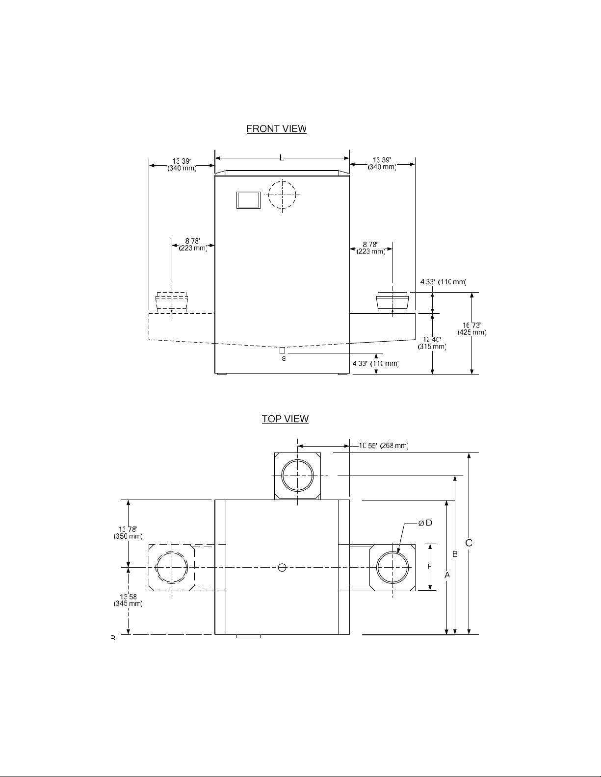
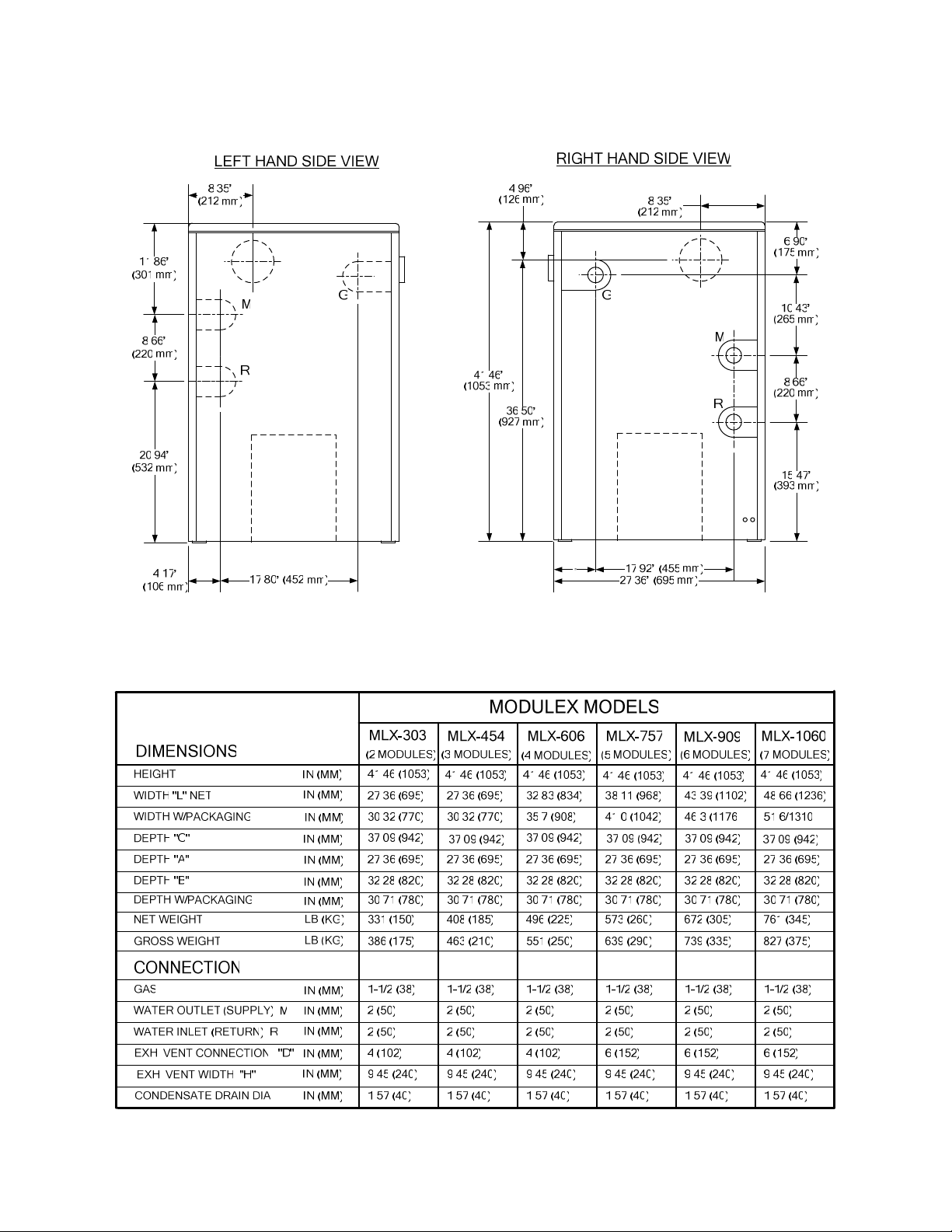
1.4 DIMENSIONS AND WEIGHTS
The dimensions and weights for eac h Modulex Model ar e s hown in sheets 1 and 2 of Figur e 1-1.
Figure 1-1. Modulex Dimensions and Weights (Sheet 1 of 2)
1-3
Page 12
INSTALLATION, OPERATION & MAINTENANCE
Figure 1-1. Modulex Dimensions and Weights (Sheet 2 of 2)
1-4
Page 13
INSTALLATION, OPERATION & MAINTENANCE
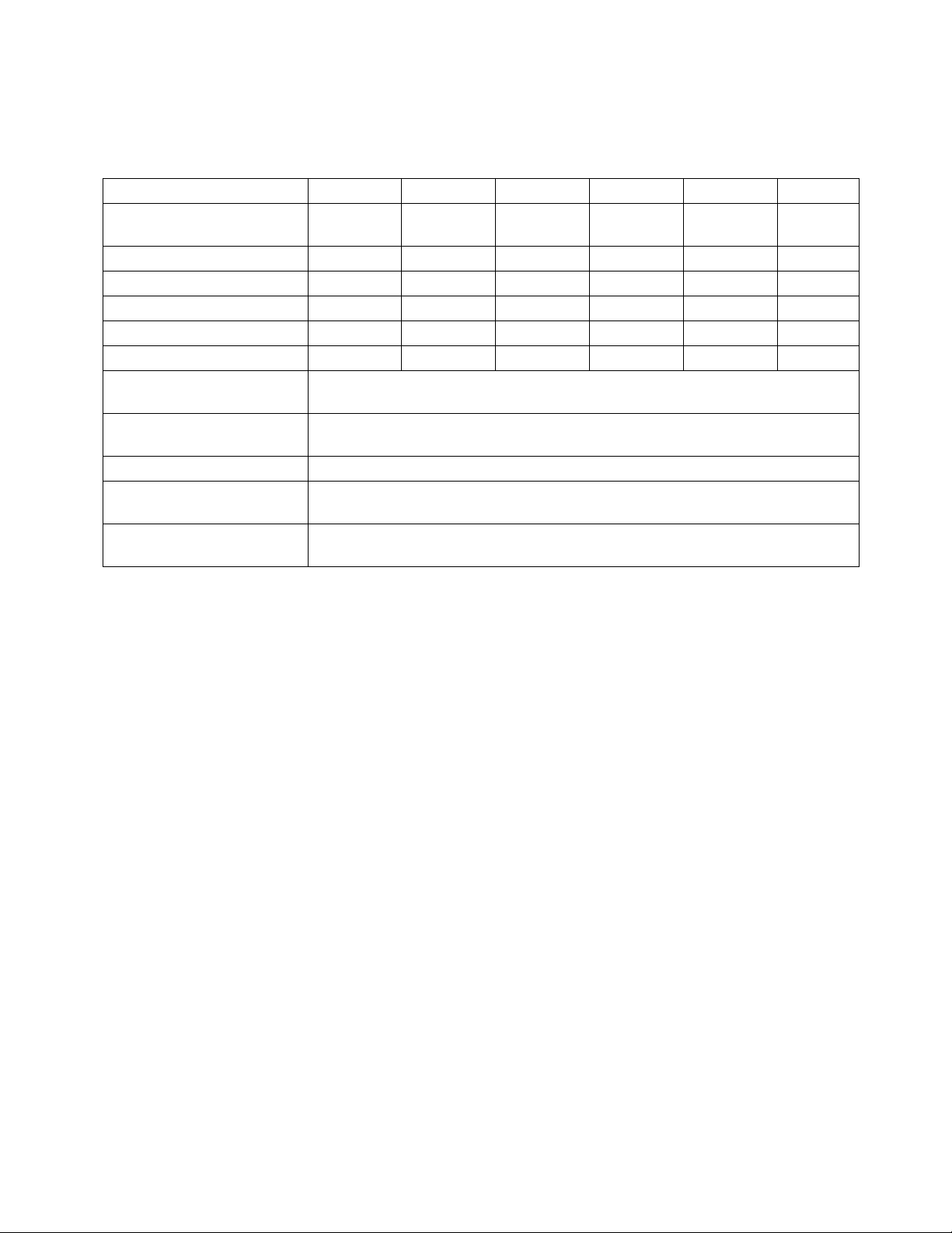
1.5 - TECHNICAL DATA
CONTROL PANEL.)
(THE NAME PLATE IS PLACED UNDER THE FRONT JACKET NEXT TO THE
Model Number Min Input Max Input Max Output* Net IBR Rating
MLX-303
MLX-454
MLX-606
MLX-757
MLX-909
MLX-1060
45,500 303,000 260,000-279,000 237,000
45,500 454,000 390,000-418,000 355,000
45,500 606,000 521,000-558,000 474,000
45,500 757,000 651,000-696,000 592,000
45,500 909,000 781,000-835,000 710,000
45,500 1,060,000 912,000-975,000 829,000
DIMENSIONS:
Model Number Height Width Depth Weight
MLX-303
MLX-454
MLX-606
MLX-757
MLX-909
MLX-1060
42” (1067 mm) 28” (711 mm) 27” (686 mm) 331 lbs. (150.1 kg)
42” (1067 mm) 28” (711 mm 27” (686 mm) 408 lbs. (185.1 kg)
42” (1067 mm) 33” (838 mm) 27” (686 mm) 496 lbs. (225.0 kg)
42” (1067 mm) 38” (965 mm) 27” (686 mm) 573 lbs. (259.9 kg)
42” (1067 mm) 44” (112 mm) 27” (686 mm) 672 lbs. (304.8 kg)
42” (1067 mm) 49” (1245 mm) 27” (686 mm) 761 lbs. (345.2 kg)
SPECIFICATIONS:
Model Number MLX-303 MLX-454 MLX-606 MLX-757 MLX-909 MLX-1060
Boiler Category IV IV IV IV IV IV
Type of Gas
Gas Connections (NPT) 1.5” 1.5” 1.5” 1.5” 1.5” 1.5”
Max. Gas Pressure 14” W.C.
Optimal Gas Pressure 7” W.C.
Min. Gas Pressure 4”
Max. Allowed Working
Pressure
Electrical Req:
120V 15 Amp. Max.
Water Connections
(NPT)
Min. Water Flow (GPM) 11 17 22 28 38 39
Max. Water Flow (GPM) 28 42 55 70 84 98
Water Pressure Drop
@ Max. Flow (Ft. of
Head)
Natural Gas
(MLX-303B)
or Propane
(MLX-303BP)
(34.8 mbar)
(17.4 mbar)
(10 mbar)
50 psi
(344.7 kPa)
1.2 FLA 1.8 FLA 2.4 FLA 3.0 FLA 3.6 FLA 4.2 FLA
2” 2” 2” 2” 2” 2”
10.5 10.6 11.6 12.6 13.7 16.1
Natural Gas
(MLX-454B)
or Propane
(MLX-454BP)
14” W.C.
(34.8 mbar)
7” W.C.
(17.4 mbar)
4”
(10 mbar)
50 psi
(344.7 kPa)
Natural Gas
(MLX-606B)
or Propane
(MLX-606BP)
14” W.C.
(34.8 mbar)
7” W.C.
(17.4 mbar)
4”
(10 mbar)
50 psi
(344.7 kPa)
Natural Gas
(MLX-757B)
or Propane
(MLX-757BP)
14” W.C.
(34.8 mbar)
7” W.C.
(17.4 mbar)
4”
(10 mbar)
50 psi
(344.7 kPa)
Natural Gas
(MLX-909B)
or Propane
(MLX-909BP)
14” W.C.
(34.8 mbar)
7” W.C.
(17.4 mbar)
4”
(10 mbar)
50 psi
(344.7 kPa)
Natural Gas
(MLX-1060B)
or Propane
(MLX-1060BP)
14” W.C.
(34.8 mbar)
7” W.C.
(17.4 mbar)
4”
(10 mbar)
50 psi
(344.7 kPa)
1-5
Page 14
INSTALLATION, OPERATION & MAINTENANCE
SPECIFICATIONS: (continued)
Model Number MLX-303 MLX-454 MLX-606 MLX-757 MLX-909 MLX-1060
Water Pressure Drop @
Max. Flow
Water Volume: Gallons 2.7 3.8 4.9 6.0 7.1 8.2
Water Volume: Liters 10.2 14.4 18.5 22.7 26.9 31.0
Thermal Modules 2 3 4 5 6 7
Turn-Down Ratio 6:1 10:1 13:1 16:1 20:1 23:1
Vent Size 4” (102 mm) 4” (102 mm) 4” (102 mm) 6” (152mm) 6” (152mm) 6” (152mm)
Vent Materials (per local
code)
Temperature Control
Range
Maximum Noise Level All units deliver <50 dBA when operating at or below full fire.
NOx Emissions
Certification
Standard Listings &
Approvals
5 psi
(34.5 kPa)
Can support PVC, ABS, CPVC, or AL29-4C venting materials.
All units can be applied to deliver 50°F to 185°F (10°C to 85°C) supply water.
All units have been certified by SCAQMD and TCEQ for <30 ppm NOx.
6 psi
(41.4 kPa)
All units have been certified by CSA.
9 psi
(62.1 kPa)
(68.9 kPa)
10 psi
13 psi
(89.6 kPa)
15 psi
(103.4 kPa)
1.6 MODULEX SIDE VIEW SHOWING MAIN COMPONENTS
Figure 1-2 on the following page illustrates the Main Components included in each Modulex Boiler
Model. In addition, an exploded view parts lis t drawin g is inc luded in App endix B .
1-6
Page 15
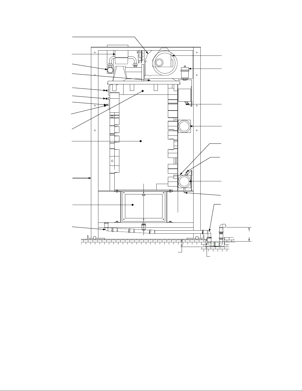
FAN
INSTALLATION, OPERATION & MAINTENANCE
GAS VALVE
GAS PIPE
BURNER
COVER
IGNITION
FLAME
DETECTOR
LOCAL NTC
SENSOR
H.L.
THERMOSTAT
BURNER
ALUMINUM/
SILICON HEAT
EXCHANGER
BOILER
FRAME
CONDENSATE
COLLECTION
TRAY MANIFOLD
AIR INTAKE
CONNECTION
AUTOMATIC
AIR VENT
GLOBAL FLOW
NTC TEMPERATURE
SENSOR
HOT WATER
OUTLET (SUPPLY)
1/4" CONNECTION
WITH PLUG
GLOBAL RETURN
NTC TEMPERATURE
SENSOR
COLD WATER INLET
(RETURN)
WATER DRAIN
VALVE
CONDENSATE
DRAIN TRAP
FILLING-UP
ELBOW
[100 mm]
4"
1" [25 mm]
5.9" [150 mm]
Figure 1-2.
Modulex Main Components
1.7 BOILER FREEZE PROTECTION
Should the boiler wat er ou tl et temperature decrease t o les s tha n 4 4.6 °F ( 7°C), the system pump will star t.
Should temperature dec rea se to less than 37.4°F ( 3°C), all heat modules will start at minimum output until
the return temperature reac hes 50°F ( 10°C). Suc h a protecti on devic e is exc lusivel y for the boiler. For the
protection of the whole system, a second freeze protection thermostat is necessary to switch on the
heating system pump.
NOTE
If glycol is used as antif reeze in the boi ler, a back flow preventer m ust be installed in t he
make-up/fill line.
1-7
Page 16

Page 17
INSTALLATION, OPERATION & MAINTENANCE
INSTRUCTIONS FOR INSTALLERS
2
2.1 INTRODUCTION
The Modulex Boiler is intended to be installed as a Category IV vent installation and m ust be installed
in compliance with all applicable laws and regulations including the ones below. See section 3.1 for
Category descriptions.
Before boiler installation, complete all of the following
instructions:
The installation mus t conform to the requir ements of the authorit y having juris diction or, in t he absenc e
of such requirements, to one of the following:
• United St ates - Installation must conform to the requirem ents of the National Fuel Gas Code,
ANSI Z223.1 Installation Codes.
• Canada - Installation must conform to the r equirem ents of CAN/CG A B149 Install ation Codes .
Where required by the authority having jurisdiction, the installation must conform to the Standard for
Controls and Safety Devices for Automatically Fired Boilers, ANSI/ASME CSD-1.
NOTES:
• Installers must follow local regulations with respect to installation of Carbon
Monoxide (CO) Detectors. Also, follow the maintenance recommendations in this
manual.
• FOR MASSACHUSETTS INSTALLATIONS: The boiler must be installed by a
plumber or gas fitter licensed within the Commonwealth of Massachusetts.
Also, for installations in buildings used for residential purposes, if a side-wall vent
termination is less than 7 feet above grade, an NFPA 720 compliant, ANSI/UL 2034
listed and IAS certified carbon monoxide detector must be installed on the floor level
where the boiler is installed and on each level of the building served by the boiler.
2.2 INSTALLATION INSTRUCTIONS
The following paragraphs in this Section provide the instructions to unpack and install the Modulex Boiler.
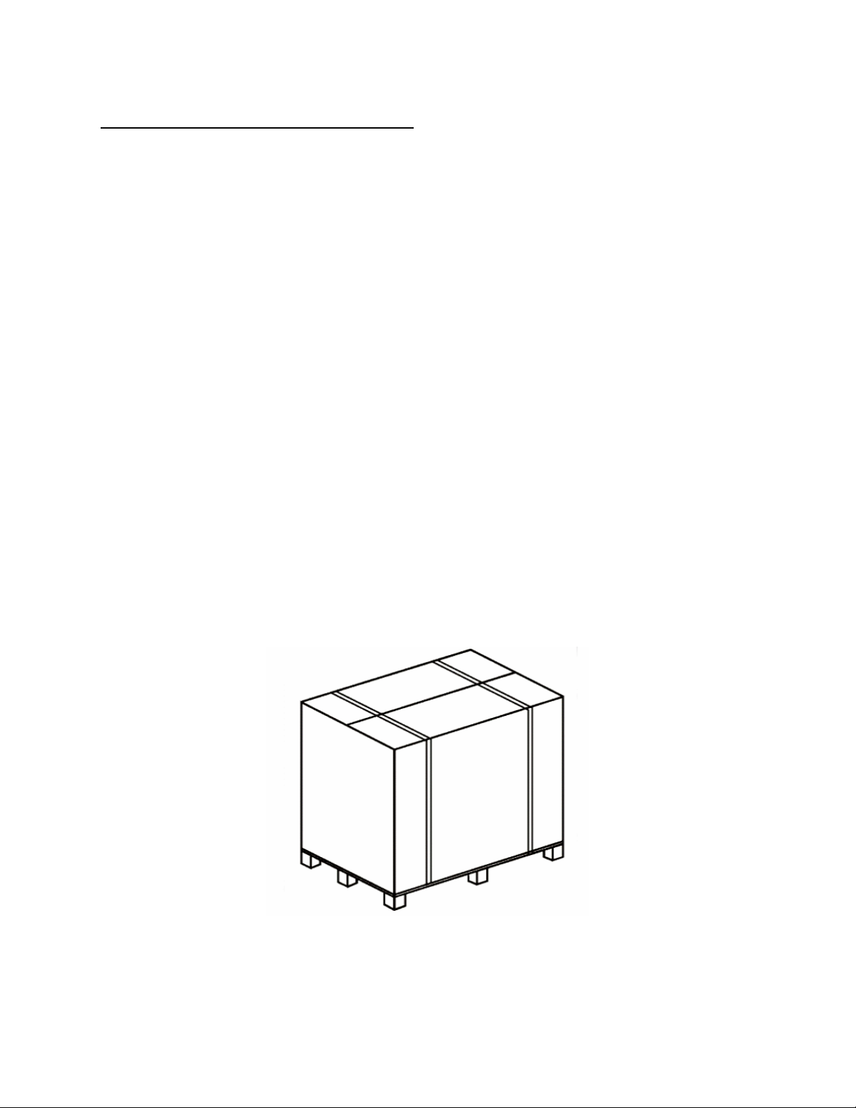
2.2.1 Unpacking the Boiler
The Modulex Boiler is delivered ass embled and protected by a plastic bag inside a rugged cardboard
box, which is fixed on a pallet ( see Figure 2- 1). T he pallet allo ws the boi ler to be handle d by a f ork lift or
pallet jack. The boiler, with the p ac kaging, can fit through a door wa y of 32 in. (8 1 cm), whereas, without
packaging, it can fit through a doorway of 28 in. (71 cm). To unpack the Modulex , remove both straps
and then the cardboard box from above. Chec k to ens ure that the pr oduc t is intac t.
The packing elements (cardboard box, straps, plastic bags, etc…)
must not be left in children’s hands since they may be dangerous.
2-1
Page 18
INSTALLATION, OPERATION & MAINTENANCE
Packed inside the boiler packing you w ill f ind:
• Painted steel panels:
• The front one connected to the back panel by a shrink wrap f ilm
• The right hand side panel connected to the left hand panel b y shrink wrap
On the front of the boiler:
• Flue collector, with exhaust connector screwed to the pallet: 6 inc h for models 303 to 606 and 8
inch for models 757 to 106 0. Use these it ems only when the specif ied flue pipe s ize is incr eased
to 6” (for models 303 to 606) and 8” (for models 757 to 1060). Otherwise, use the exhaust
connector “shipped in the separate carton” described below (4” for models 303 to 606, 6” for
models 757 to 1060).
• A plastic bag c ontaining 3 gaskets (1 rectangular for condensate tra y and flue collector , 1 square
for exhaust connector.
• T hr ee (3) s urface-mount s trap-on s ensor s.
• Screws necessary for accessory installation.
• Pipin g f or 1 ½” c ondens ate drain, inc lud ing one t ee a nd two 90 degree elbo ws.
On the back of the boiler:
• Plas tic c ondens ate drainp i pe, 38.5 inc hes ( 1meter) long, placed under the casing rear panel.
• O utside air sens or with 49 f eet, 2.5 inches ( 15 m) c able.
• Manual G as Shutoff Valve.
Shipped in a separate carton are the following:
• Accessory kit that includes a CSD- 1 installation kit, P/N 29031 for Models 303 through 606 and
P/N 29032 for Models 754 through 1060. See the pac k ing list shipped in t his m anual pack age f or
a complete listing of access ories and paragr aph 4.4 f or m ore info rm ation about the CSD 1- k its .
Figure 2-1.
Packaged Modulex Boiler
2-2
Page 19
INSTALLATION, OPERATION & MAINTENANCE
2.2.2 Locating the Boiler
The boiler should be located on a level, solid area or base as near to the outside wall as possible and
centrally located to the space heating d istribution syst em. Special attention must be given to local regulations
and codes about b oiler rooms and par ticu lar ly t o th e m ain tai ning of mi nim um c lear anc es and empty space
around the boiler. The installation must be in compliance with all recent regulations and laws about boiler
rooms, installations of heating and hot water systems, ventilation, boiler venting systems capable of
evacuating the flue gases of condensing boilers and any other applic able req u ire m ent.
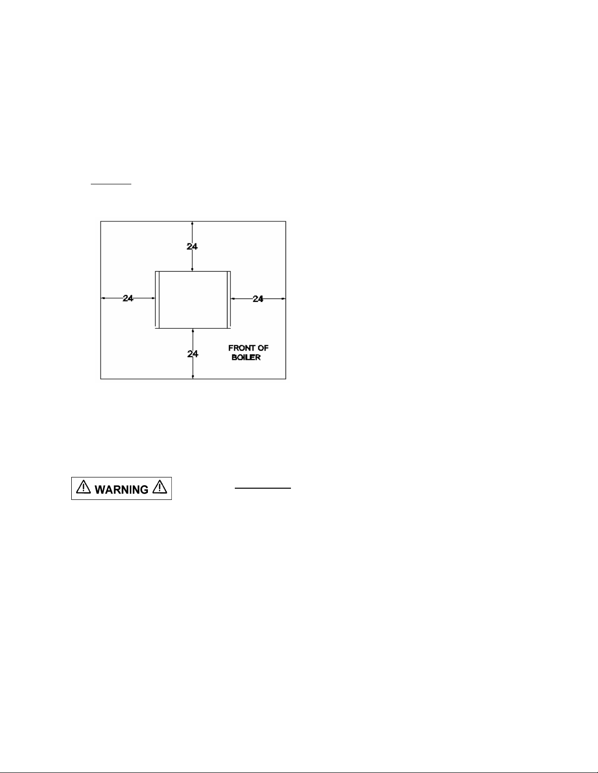
The minimum clearanc e dimensions for service acc ess, required by AERCO, are lis ted below (Figure 2-2)
and on the boiler Data Plate shown in Figure 2-7. Local building codes may require more clearance and
take precedence.
Minimum clearances required:
Sides 24" (510 mm)
Front 24" (510 mm)
Rear 24" (510 mm)
Top 24" (510 mm)
Figure 2-2
Boiler Clearances (Top View)
NOTE: All gas piping, water piping and electrical conduit or cable must be arranged so that
they do not interfere with the removal of any cover, or inhibit service or maintenance of the
unit.
The boiler MUST NOT be installed on carpeting
2.2.3 Pad Height for Boiler
To properly drain and service the boiler’s condensate system, attention must be given to installation
requirements regarding the mounting heig ht of the boiler as well as installatio n clearances for the removal
of the condensate collector baffle.
The boiler should be mounted on a flat and sufficiently strong base with the same dimensions as the boiler
(see Figure 1-1) and at least 4 inches (100mm) high (see Figure 4-1 in paragraph 4.7), to allow for
assembly of the condensate drain trap. An alter native to this base m ay be a 4 inc h (100mm ) deep well nex t
to the boiler to house the condensate siphon.
The condensate collector baffle (see Section 7) can be fixed, from the Right Hand (R.H) or Left Hand (L.H.)
side of the condensate tray. If no modification has been made, the boiler must have its R.H. side
accessible, with the vent connection f itted on the R.H or L.H. side. However, if the flue collector term inal,
with the exhaust connector, is left to of the R.H. side and if, from this same side, the baffle has to be
removed, and then the exhaust connector must have the possibility to be also removed. If it is preferred,
the baffle can be moved in order to have its mounting s crew on the oppos ite side , regardles s the positi on of
the flue collector chamber term inal.
2-3
Page 20

INSTALLATION, OPERATION & MAINTENANCE
2. 2 .4 Boiler Connections
Upon delivery, the Modulex Boiler has all the connections on its R.H. side (Figure
2-3). Note that the R.H. orientation is the right hand s ide when viewed facing the fr ont of the boiler. These
connections include: water supply and return, gas, combustion air intake and flue collector outlet. The
locations of the air intake and/or the flue c ollector outlet c an be changed on site by rem oving knock -outs on
the boiler right, left or back side panels. To attach the exhaust connector to the flue collector, use the
screws and the gaskets supplied inside the plastic bag and us e a cross-tip (Phillips ) screwdriver at leas t 12
in. (300 mm) long.
Figure 2-3.
Boiler Connections
Water supply and return and gas connections c an also be moved to the boiler’s L.H. side by inverting the
flow (supply)/return manifold on the left side using the following procedure:
1. Remove the front, side and rear panels f r om the boiler .
2. For revers al of the water flow (supply) and return manifolds from the R.H. to the L.H. side, rem ove
the small plates securing the flow (s upply) an d retur n global t emperature sensors (Figure 2-4) .
2-4
Page 21

INSTALLATION, OPERATION & MAINTENANCE
Figure 2-4
Right Hand (R.H.) Connection
2-5
Page 22

INSTALLATION, OPERATION & MAINTENANCE
3. Dis ass e mb l e th e fl ow (supply) and return manifolds (F igure 2- 5), lea ving the rubber gaskets in place
on the upper holes of the aluminum sections and the diaphragms in plac e on the lower holes. The
diaphragms on the end sec tions have a ho le diam eter of .669 in. (17 mm ), while the gask ets on the
upper holes have a hole diameter of .866 in. (22 mm).
4. Reassemble the manifolds with the threaded connec tion on the opposite side as shown in Figure
2-5. Change the position of the drain cock and the automatic air vent (Figure 2-6) .
5. Reposition the tem perature sensor white and red leads onto the new flow (supply) manifold and the
temperature sensor white and green leads onto the n ew retur n manifold.
Figure 2-5
R.H. and L.H. Manifold Connection
2-6
Page 23

INSTALLATION, OPERATION & MAINTENANCE
Figure 2-6
Left Hand (L.H.) Connection
2-7
Page 24

INSTALLATION, OPERATION & MAINTENANCE
6. For the gas connection, it i s poss ible to k eep the gas manif old inlet on the R.H. s ide, if desir ed, or it
can be rotated 180° to have it on the L.H. side. In case of reversal from R.H. side to L.H. side of the
gas manifold, only on the Modulex Mo del 303 will it be necessary to reverse plug C with the gas
valve fitting A (see gas manifold connections in Figur e 2- 5).
The boiler and its individual shutoff valve must be disconnected from the gas supply piping system during
any pressure testing of that system at test press ures in exces s of 0.5 ps i ( 14” W .C., 3.5 kPa).
The boiler must be isolated f rom the gas s upply piping s ystem by closing its indivi dual m anual shutof f valve
during any pressure testing of the gas suppl y piping system at test pressures equal to or less than 0.5 psi
(3.5 kPa).
The boiler shall be installed such that the gas ignition system components are protected from water
(dripping, spraying, rain, etc.) during appliance operation and service (cir culator replacement, condensate
trap, control replacement etc.).
Before operating the boiler, the com plete gas train and all connections must be leak tested using a noncorrosive soap solution.
2.3 DATA PLATE
A sample Data Plate for a Modulex Boiler is shown in Figure 2-7. The data in Table 2-1 following this
Figure indicates the required entries f or each Modulex Model.
2-8
Page 25

INSTALLATION, OPERATION & MAINTENANCE
Figure 2-7
Sample Data Plate
2-9
Page 26

INSTALLATION, OPERATION & MAINTENANCE
Table 2-1. Modulex Data Plate Entries
MODEL NUMBER MLX-303 MLX-454 MLX-606 MLX-757 MLX-909 MLX-1060
REVISION
TYPE OF GAS
*SERIAL NO.
MAX INPUT
MIN INPUT
OUTPUT
NET IBR RATING
BOILER CATEGORY
MAX INLET (SUPP LY)
GAS PRESSURE
MIN INLET ( SUPPLY)
GAS PRESSURE
*NORMAL MANIFOLD
GAS PRESSURE
OPTIMAL INLET
(SUPPLY) GAS
PRESSURE
* NOTE: Normal manifold gas press ur e measur ed at downstream por t of gas valve ( (F igure 6- 2).
A A A A A A
NATURAL GAS
(MLX-303B)
OR PROPANE
(MLX-303BP)
303-XX-XXXX 454-XX-XXX 606-XX-XXXX 757-XX-XXXX 909-XX-XXXX
303,000 454,000 606,000 757,000 909,000 1,060,000
45,000 45,000 45,000 45,000 45,000 45,000
279,000 418,000 558,000 696,000 835,000 975,000
237,000 355,000 474,000 592,000 710,000 829,000
IV IV IV IV IV IV
14” W.C
(34.8 mbar).
4”
(10 mbar)
3.2” Nat. Gas
(MLX-303B)
2.5” Propane
(MLX-303BP)
7.0”
(17.4 mbar)
NATURAL GAS
(MLX-454B)
OR PROPANE
(MLX-454BP)
14” W.C
(34.8 mbar).
4”
(10 mbar)
3.2” Nat. Gas
(MLX-454B)
2.5” Propane
(MLX-454BP)
7.0”
(17.4 mbar)
NATURAL GAS
(MLX-606B)
OR PROPANE
(MLX-606BP)
14” W.C
(34.8 mbar).
4”
(10 mbar)
3.2” Nat. Gas
(MLX-606B)
2.5” Propane
(MLX-606BP)
7.0”
(17.4 mbar)
NATURAL GAS
(MLX-757B)
OR PROPANE
(MLX-757BP)
14” W.C
(34.8 mbar).
4”
(10 mbar)
3.2” Nat. Gas
(MLX-757B)
2.5” Propane
(MLX-757BP)
7.0”
(17.4 mbar)
NATURAL GAS
(MLX-909B)
OR PROPANE
(MLX-909BP)
14” W.C
(34.8 mbar).
4”
(10 mbar)
3.2” Nat. Gas
(MLX-909B)
2.5” Propane
(MLX-909BP)
7.0”
(17.4 mbar)
NATURAL GAS
(MLX-1060B
OR PROPANE
(MLX-1060BP)
1060-XX-
XXXX
14” W.C
(34.8 mbar).
4”
(10 mbar)
3.2” Nat. Gas
(MLX-1060B)
2.5” Propane
(MLX-1060BP)
7.0”
(17.4 mbar)
2-10
Page 27

INSTALLATION, OPERATION & MAINTENANCE
3
GENERAL INFORMATION FOR VENTING
Note: See Venting Guide GF-115-V for venting specifications and materials.
3.1 VENT PIPE CONNECTION
The Modulex boiler is approved f or a Category IV vent c onfiguration as well as
for sealed combustion installations. Provisions for combustion and ventilation
air in accordance with section 5.3, Air for Combustion and Ventilation, of the
National Fuel Gas code, ANSI Z223.1, or Sections 7.2, 7.3, or 7.4 of CAN/CGA B149, Installation
codes, or applicable provisions of the local building codes.
Maintain clearances from combustible construction for boiler, vent connector,
and steam and hot-water pipes.
3.2 GAS VENT CATEGORIES
Federal Codes have categorized gas appliances by the vented flue gas pressure and temperature.
These categories are defined as f ollows:
Category I
•
vent) connector with a flue gas pressur e and temperature at least 140°F (60°C) above its de w
point.
Category II
•
vent) connector with a flue gas pressure and temperatur e less than 140 degrees F (60 degrees
C) above its dew point.
, being a gas appliance that operates with a non-positive vent (or natural drafted
, being a gas appliance th at operates with a non-positiv e vent (or natural draf ted
•
Category III
connector with a flue gas pressure and temperature at least 140 degrees F (60 degrees C)
above its dew point.
•
Category IV
connector with a flue gas pres sure and temperature less than 140 degrees F (60 degrees C)
above its dew point.
•
Direct Vent
derived directly from the outdoors and all f lue gases are dis c harged to the outd oor s .
3.3 INSTALLATION AND SIZING
The AERCO Venting Guide, G F-115-V, mus t be consulted bef ore any flue gas vent or air inlet piping is
designed or installed. Cer tified venting materials specified in GF-115-V m ust be used for safety and
code compliance. Because the Modulex boiler is capable of discharging low temperature exhaust
gases, the flue must be pitched back to the unit a minimum of ¼” per foot to avoid any condensate
pooling and to allow for proper dr ainage.
For side wall venting in Massachusett s:
• The vent termination must be located at a minimum of 4 feet above grade leve l.
• IMPO RTANT: See pages v and vi of this manual (GF-115) for detailed information pertaining
to side wall venting within the Comm onwealth of Massac hus etts.
, being a gas appliance that operates with a positive vent (fan forced vent)
, being a gas appliance that operates with a positive vent (fan forced vent)
, a gas appliance is constructed and installed so that all air for combustion is
3-1
Page 28

INSTALLATION, OPERATION & MAINTENANCE
Pipe lengths and fittings must be calc ulated as part of the equivalent length. The press ure drop of the
vent and combustion air s ystems m ust not exc eed 100 equivale nt feet eac h. Note that this DOES NOT
mean the allowed combined pressure drop between the vent and com bustion air is 200 equivalent f eet.
That is, the vent cannot go above 100 equivalent feet, even if the combustion air is less than 100
equivalent feet, and vice vers a. (See G F- 115- V for detailed si zing guid elin es .)
The combustion air must be free of chlorine, halogenated h ydrocarbons, or other chemic als that can
become hazardous when used in gas-fired equipment. Common sources of these compounds are
swimming pools, degreasing compounds, plastic processing compounds and refrigerants. Whenever
the environment contains t hese types of chemic als, combus tion air m ust be supplied f rom a c lean area
outdoors for the protection and longevit y of the equi p m ent.
The Modulex is CSA listed f or 100% sealed combustion or can be ins talled using room air as long as
there is an adequate supply. (See GF- 115-V f or detailed s izing guid elin es .)
3.4 REMOVAL OF EXISTING BOILER FROM COMMON VENTING SYSTEM
At the time of removal of an exis ting boiler, the following steps shall be followed with eac h appliance
remaining connected to the common venting system placed in operation, while the other appliances
remaining connected to the common venting system are not in operation.
1. Seal any unused openings in the common venting system.
2. Visually inspect the venting s ystem for proper s ize and horizontal pitch an d determ ine there are
no blockages or restrictions, leakage, corrosion and other deficiencies that could cause an
unsafe condition.
3. W hen practic al, close all buildi ng doors and windows as well as all do ors between the s pace in
which the appliances remaining connected to the common venting system are located and
other spaces of the building. Turn on any appliances not connected to the common venting
system, such as clothes dryers. Turn on an y exhaust f ans, such as range hoods and bathroom
exhausts, so they will operate at maximum speed. Do not operate a summer exhaust fan.
Close fireplace dampers.
4. Turn on the appliance being inspected. Follow the lighting instructions. Adjust thermostat so
appliance will operate continuous l y.
5. T est for spillage at the draf t hood relief opening af ter 5 minutes of main bur ner operation. Use
the flame of a match or candle, or smok e fr om a cigarette, c igar or pipe.
6. After it has been deter mined that each appliance re maining connected to the c ommon venting
system properly vents when tested as outlined above, return doors, windows, exhaust fans,
fireplace dampers and any other gas- burning appl ian c e to their pr evious s tate o f us e.
7. Any improper oper ation of the common venting system should be corrected so the installat ion
conforms to the National Fuel Gas code, ANSI Z223.1 and/or CAN/CGA B149, Installation
Codes. When resizing any portion of the c omm on venting s ystem, the c ommon venting s ystem
should be resized to approac h the minimum size as determined using the appro priate tables in
Part 11 of the National Fuel Gas Code, ANSI Z223.1 and/or CAN/CGA B149, Installation
Codes.
3-2
Page 29

4
PIPING
NOTE: For in depth piping information for the boiler, see Piping Guide
GF-115-P
4.1 MAKEUP WATER QUALITY
Water at the installation should be checked, monitored, maintained and treated as described in
GF-115-P.
NOTE: Failure of the boiler due to water quality is not covered under warranty.
4.2 - MAXIMUM ALLOWABLE WORKING PRESSURE
The Modulex boiler has a maximum allowable working pressure of 50 psi
(345kPa, 3.5 bar), and a minimum of 15 ps i (103 k Pa, 1 bar).
4.3 BOILER LOOP DESIGN GUIDELINES
For proper and safe opera tion of the water tube Mod ulex boiler, the prim ary (boiler) loop piping an d the
associated fittings and accessories must be designed/selected as discussed in the following sections
4.4 CSD-1 MANIFOLD ASSEMBLY (SUPPLIED)
The installation of a low water cutoff, manual res et high limit aquastat and an ASME compliant safety
pressure relief valve designed for the boiler output capacity are required. These major components
along with a manifold and sever al others ar e supplied with the bo iler and m us t be assem bled and wired
when installing the boiler at the site. The manifold assembly com ponents s upplied are:
• 3/4” Pressure Relief Valve
• Manifold Assembly [2” x 16” long (51 m m x 406 mm ) ]
• 2” NPT Union
• Low Water Cut-Off Switch
• Aquastat
• Pressure/Temperature Gauge
4.5 CONNECTING SUPPLY AND RETURN PIPING (PER ANSI Z21.13A)
• The boiler, when used in connection with a refrigeration system , must be installed so the chilled
medium is piped in parallel with the boiler with appropriate valv es to prevent the chilled m edium
from entering the boiler.
• T he boiler piping system of a hot water boiler connec ted to heating c oils located in air h andling
units where they may be exposed to refrigerated air circulation must be equipped with flow
control valves or other automatic means to prevent gravity circ ulation of boiler water durin g the
cooling cycle.
• A ho t water boiler installed abo ve radiation level or a s required by Authority ha ving jurisdiction,
must be provided with a lo w water cutoff device either as a part of the boiler or at the tim e of the
installation.
4-1
Page 30

INSTALLATION, OPERATION & MAINTENANCE
4.6 SYSTEM FILLING & DRAINING
• For filling-up the system a fi ll in g t ap has to be i nser ted on the system return pipe.
• The filling-up can also be m ade through the dr aining tap on the boiler return manifold.
• In both cases, an approved hydraulic disconnection system has to be fitted.
• Before connecting the boiler, carefull y rinse out the whole s ystem with running water.
4.7 NOTES ON CONDENSATE DRAIN
To maintain proper flow of condens ate the drain pipe must slope toward t he drain of at least 3/8 in./ft.
(30 mm/m). The liquid column inside the condensate siphon needs to be filled with water after
installation. Its minim um height when all the fans are in operation mus t be at least 1 in. (25 mm) . See
Figure 4-1. In order to help avoid ice from forming, the condensate piping system must be well
insulated.
DO NOT INSTALL THE CONDENSATE DRAIN WHERE FREEZING MAY
OCCUR.
Consult local codes with regar d to condensate neutrali zation. Neutralizat ion can be obtained b y mixing
it with the buildings drain water or with limestone, which normall y have a base p H.
Figure 4-1
Typical Condensate Drain Installation
4.8 GAS MAINS AND CONNECTIONS
• Connect gas service m eter to control assembly in accordance with the current version of the
ANSI Z223.1 and the local codes or utilit y.
• Prior to operation, the complete gas tr ain must be leak tested using a non-cor rosive soap.
• For gas pipe sizing and additional deta ils , see G F -115- P.
4-2
Page 31

INSTALLATION, OPERATION & MAINTENANCE
5
ELECTRICAL
NOTE: For additional electrical information, see Electrical Power Guide
GF-115-E
5.1 ELECTRICAL CONNECTIONS
A complete electrical wiring diagram for the Modulex is provi ded under separate cover in the m anual
package. For electrical ratings, refer to the technical data in paragraph 1.5. The boiler installation
requires a 120 VAC, 60 Hz – single-phase power input. The electrical connections must conform to
local and NEC or CEC require ments. Utilization of adapters, m ultiple sockets or extensions cords ar e
not permitted. It is imperative that these safety requirements be adhered to. If in doubt, request an
accurate assessment of your electric system by highly qualified personnel.
AERCO is not liable for any dam age caused by connection to an im proper grounding system. The gas
and water feeding pipes and the central heating system pipes cannot be used as grounding means.
Boiler electric safety is guaranteed onl y when it is properl y connected to an eff ective groundin g s ystem,
which is in compliance with the r egulati ons in f orc e.
The use of any electrically powered equipment implies the observance of some fundamental rules, such
as:
• Do not touch the boiler with any wet part of your body and/or barefooted; do not pull the
supply cable.
• Do not expose the boiler to sunlight, rain, etc.
• Keep the boiler away from untrained people.
WARNING
The boiler’s electric al supplying cable mus t not be replaced by the user. In cas e of any
damage to the cable, stop the boiler and contact qualified personnel for its replacement.
IMPORTANT
Prior to connecting ex ternal AC power to the Modulex boiler, the CSD-1 Su pply Manifold
must be installed using the procedures described Piping Manual GF-115-P.
1. Ex ternal power at 120 VAC, 60 Hz, single phase is first connected to the Low Water Cutoff and
Aquastat provided on the CSD-1 Supply Manifold. Refer to Wiring Diagram 68004 provided in
the manual package for connections to the CSD- 1 Ma nif old.
2. Following connection of 120 VAC power to the CSD-1 Manifold, the power lead s are routed to
the Junction Box shown in Figure 5-1. The Junction Box is accessed by removing the front
panel from the boiler.
3. Route the wires from the CSD-1 Manifold thr ough the cutout labeled 120V on the Left side of
the boiler. If necessary, the cutout labeled 24V is used for low voltage s ignals such as external
sensors.
4. The boiler’s J unction Box c ontains a po larized term inal block . Therefore, th e Red (Line - L1) and
White (Neutral - L2) wires from the CSD-1 Manifold MUST BE
L2 respectively on the term inal block in the Junction Box. The output cable from the Junction
Box is terminated with a 3- pole plug, which connects to the boiler’s electrical c omponents. If
incorrectly wired, the boiler goes into a “lockout” condition.
connected to terminals L1 and
5-1
Page 32

INSTALLATION, OPERATION & MAINTENANCE
5.
It is necessary to install a double-pole switch on the supply line in an easily accessible position in
order to quickly and safely disconnect service. Do Not affix switch to boiler sheet metal
enclosure.
Figure 5-1. Junction Box Wiring Connections
After placing the boiler in operation, the ignition system safety shutoff device must be tested. If an
external electrical s ource is utilized, the boiler, when ins talled, must be electricall y bonded to ground in
accordance with the requirements of the authority having jurisdiction or, in the absence of such
requirements, with the National Electrical code (NEC), ANSI/NFPA 70 and/or the Canadian Electrical
Code (CEC) Part I, CSA C22.1, Electrical Code.
5.2 DHW STORAGE TANK
Domestic hot water (DHW) production by an external storage tank connected to the boiler can be
implemented by an electric diver tin g va lve or a s epar ated s torage tank loading pump. See Figure 5- 2.
The DHW tank temperature sensor will be connected to the terminals 3 (F3) and 4 (GND) of E8
Controller connector number I.
5.3 ENABLE/ DISABLE
Enable/Disable: it shal l be connected to the terminals 3 (F3) and 4 (GND) of E8 Controller connector
number I.
5.4 INSTALLATION OF SENSORS
To avoid electromagnetic interf erence, it is necessary to separate any external s ensor wiring (between
sensor and terminal strip) from an y 120 VAC po wer wiring.
5-2
Page 33

INSTALLATION, OPERATION & MAINTENANCE
Figure 5-2.
5-3
Page 34

Page 35

INSTALLATION, OPERATION & MAINTENANCE
6
BOILER OPERATION
6.1 GENERAL DESCRIPTION AND OPERATION
The Modulex is a cast alum inum body boiler consisting of mutually connected c ombustion chambers,
each having its own burner, blower and air pressure switch, gas valve, ignitor and flame detection.
Each group of these components is r ef erred to as a m odule.
The boiler has supply and retur n temperature sensors that the System (E8) Manager uses to monitor
total outlet temperature from each module and the system return water temperatures before being
redistributed to each module. These s ensors are negative temperature coefficient (NTC) sensors and
are designated the Global Flow Sensor for the supply sensor and the Global Return for the return
sensor (see Figures 2-4 and 2-6) . Each module has its o wn temperature sensor called the Local Flow
NTC, which monitors the water temperature of eac h module. The water temperature measured by the
Local NTC sensor is compared to the return supply water temperature. If for any reason the
temperature difference between the Loc al Flow and the Glo bal Return temperatures becomes greater
than 54°F (30°C), the module or modules will begin to modulate as follows:
0°F to 54°F (0°C to 30°C) Normal Operation
54°F to 63°F (30°C to 35°C) Burner will begin Modulating down
o
63
F to 72oF (35°C to 40°C) Burner will stay at 45,500 BTU’s
Above 72°F (40°C) Burner will shut off
The variable speed fan's pressur e drives the gas valve to allow gas to enter into the pre-combustion
chamber where it mixes with the combus tion air. T he mixed air and gas pass thru the check valve on to
the burner surface for ignition. Com bustion gases pass thru the heat tr ansfer surfaces. Flue gases and
condensate then exit the heat exchanger entering int o the c ondens ate tra y.
6.2 MODULATION THEORY
One of the operating principles for this boiler is to have as many modules as possible operate
simultaneously at minimum load to reach the maximum efficiency. This is maintained by the System
Manager (E8) which determ ines a percent of m odulation based on the differ ence between the set po int
temperature and the actual supply water (global flow) temperature. This operating principle provides
efficiencies much higher than those obtain ed in traditional groups of sm all boiler s ins talled in c as cade.
Each of the boiler’s modules r epresents a maximum output of 151.5 MBH (44.4 kW). The number of
modules x 100% determ ines the max imum output expres sed in percent. For exam ple, if a f our module
boiler is requested to operate at its max output, this shall be 400% i.e.
151.5 MBH (44.4 kW) x 4 modules =606 MBH (177.6 kW) = 400%.
If the required percentage is 200%, eac h module will operate at 50% output. This equals a total of 303
MBH (88.8 kW) out of a possible 606MBH (177.6 kW), and each module will be operating at 75.75
MBH (22.2 kW) out of a possible 151.5 MBH (44.4 k W).
When the output shared on each module is les s than approxim ately 30%, one module after the other is
automatically turned off and the rem aining output is shared on m odules having the smalles t number of
operation hours (by the automatic operation-time calculating system).
6-1
Page 36

INSTALLATION, OPERATION & MAINTENANCE
6.3 IGNITION SEQUENCE
The ignition sequence is descr ibed below and shown in the f ollowing diagram (Figur e 6-1). The Ignition
Burner Management Module (BMM) is powered on and, after 5 seconds the fan starts at minimum
speed. The fan remains running, actuating the air pressure switch and pre-purging the combustion
chamber for 10 seconds. Actuating the air pressure switch toggles it from normally open (NO) to
normally closed (NC). This energi zes the ignition tran sformer permits the gas valve to be opened after
5 to 8 seconds allowing the AIR/GAS m ixture into combus tion chamber through the check valve. If the
burner does not light within the ignition tim e frame, the burner is put in lockout position f or 5 sec, after
which it repeats the ignition sequence once again. If no positive result is obtained, then a lockout
conditions occurs and the displa y on the System Manager will show an err or message.
Figure 6-1.
6.4 MODES OF OPERATION
The Modulex boiler is cap able of operating in several contr ol modes including, Indoor/Outdoor Res et,
0 to 10 Volt Remote Setpoint and Constant Setpoint. The following subordinate paragraphs briefly
describe each of these modes.
NOTE
Refer to Modulex E8 Co ntroller Ma nual GF-11 5-C for additi onal inform ation on operati ng
modes, set-up and programming.
6.4.1 Indoor/Outdoor Reset
In indoor/outdoor reset mode the Modulex boiler will adjust its set-point based on the outside air
temperature and the programmed heating curve. The heati ng cur ve c an be c us tom ized b y chan ging the
Slope parameter found in the User/ Heating Cir c uit 1 m enu in the boiler s contr oller.
6-2
Page 37

INSTALLATION, OPERATION & MAINTENANCE
The outside air sensor, supplied with the boiler, should be mounted on an out er North or Northeast,
wall at a minimum height from floor of 8 feet, 2.5 inches (2.5 m) away from windows, doors and
ventilation grates. Never mount the outside air sensor in a sunny position. The connections for the
sensor are at connector number 1, term inals 9 (F9) and 10 (G ND) of the boiler controller .
6.4.2 0 To 10 Volt Remote Set-Point
The unit’s set-point can be contr olled using a 0 to 10 volt signal. The Modulex contr ols allow for full
scaling capabilities of voltage and set-point through use of the V-Curve in the Expert Menu of the
Controller. Input wiring for this mode will be to terminals 1 (F15) and 2 (GND) of the E8 Controller
connector number 3 (III).
6.4.3 Constant Set-Point
The constant set-point mode is used when a fixed header tem perature is desired. Common uses for
this mode of operation include water sourc e heat pump loops and indirect heat exchangers f or potable
ho water systems or processes. No ex ternal connections ar e requir ed f or this mode of operation.
6.4.4 Boiler Operation In Case Of Troubleshooting (Manual Mode)
For service and test pur poses, any single m odule, or all simultaneous ly, can be kept operating at f ull or
reduced load. In this way the CO
load (for any single m odule or for all simultaneo usly). With this option, trou bleshooting failures on each
module is simplified.
level can be checked and, if necessary, adjusted at full or reduced
2
6.5 MODULEX BOILER INITIAL STARTUP
Prior to initial start-up of the c om plete Modulex Bo iler, check the following item s :
• Ensure that all Installation procedures in Section 2 of GF-115 (including the referenced
documents GF-115-G, GF-115-P and G F- 115-V) have been c ompleted.
• Ensure that all operating controls, menu settings and limits have been properly set in
accordance with Section 3 of the Modulex E8 Control l er O per ation & Wiring Guide GF-115-C.
• Ensure that the mode of operation settings have been made in accordance with document
GF-115-C.
Upon completion of the above item s, perform the initial s tartup and c ombus tion calibr ation proce dures as
described in the following paragraphs.
CAUTION
ALL INSTALLATION PROCEDURES SPECIFIED IN GF-115,
SECTION 2 MUST BE COMPLETED BEFORE ATTEMPTING TO
START THE UNIT.
DO NOT ATTEMPT TO FIRE THE BOILER WITHOUT A FULL
WATER LEVEL. FAILURE TO OBSERVE THIS PRECAUTION
CAN SERIOUSLY DAMAGE THE UNIT AND MAY RESULT IN
PERSONAL INJURY OR PROPERTY DAMAGE. THIS IS NOT
COVERED BY WARRANTY.
6-3
Page 38

INSTALLATION, OPERATION & MAINTENANCE
6.5.1 Tools and Instrumentation Required For Combustion Calibration
The following tools and instrumentation are necessary to perform combustion calibration of the unit:
• Digital Combustion Analyzer: Oxygen (O
Monoxide (CO) resolution to 1 ppm
• One 16” W.C. manometer or equivalent gauge
• Small and large flat-tip screwdrivers
• T40 Torx tool
• Length of plastic tubing (3/8” I.D.)
) and Carbon Dioxide (CO2) accuracy to ±0.4%; Carbon
2
6.5.2 INSTALLING THE SUPPLY GAS MANOMETER
Install the W.C. manometer (or gauge) as follows:
1. Turn off the external main gas supply valve to the unit.
2. Remove the top panel from the Modulex boiler to provide access to gas supply manifold.
3. Refer to Figure 6-1 and locate the gas pressure tap on the gas supply manifold.
4. Using a flat-tip screwdriver, rotate the pressure tap screw counterclockwise three full revolutions
to the open position.
5. Attach one end of the length of plastic tubing to the gas pressure tap. Attach the other end to the
W.C. manometer (or gauge).
Figure 6-1. Partial Top View Showing Gas Pressure Tap
6-4
Page 39

INSTALLATION, OPERATION & MAINTENANCE
6.5.3 Preparing The Flue For Use With The Combustion Analyzer
In order to provide an opening for the combustion analyzer, proceed as follows:
1. Drill a 3/8” hole in the PVC vent pipe, approximately 2 feet above the boiler exhaust manifold.
2. If necessary, adjust the stop on the combustion analyser probe so that it will extend mid-way into
the flue gas flow. DO NOT install the probe at this time.
6.5.4 SUPPLY GAS PRESSURE CHECK & ADJUSTMENT
The optimum gas pressure for the Modulex Boiler is 7.0” W.C. and is used as the desired pressur e in
the Combustion Calibration procedures in paragraph 6.5.5. However, it should be noted that the
Modulex Boiler can be safely operated at g as press ures ranging from 4.0” W.C. (minimum) to 14” W.C.
(maximum) as specified in the G as Supply Design Guide GF-115-G.
An external gas pressure regulator is mandatory for the state of Massachusetts. For all other
jurisdictions, a lock-up st yle regulator is r equired whe n suppl y gas pres s ure is greater than 14” W.C.
In order to ensure that the supply gas pressure is adequate for the Modulex installation, the pressure
must be checked under full- f ire conditions using the f ollowing procedure:
1. Open the water supply and return valves to the unit and ensure that the system pumps are
running.
2. Open the external gas supply valve to the boiler.
3. Measure the gas press ure us ing the W.C. manometer connected to the inlet gas manifold. If an
external regulator is installed, adjust the pressure to obtain 7.0” W.C. If an external regulator is
not installed, ensure that the supply gas pressure is at least 4.0” W.C.
NOTE
When performing the remaining steps in this procedure, refer to Figures 1 and 2 in
Modulex E8 Controller O pe ration & Wiring Guide GF -1 15- C f or loc atio ns and d es cr ipti ons
of the controls and displays on the Controller.
4. Set the ON/OFF switch on the front of the boiler to the ON position.
5. With the Controller hinged panel closed, turn the Rotary Knob clockwise and monitor the
displayed symbols on the lower right portion of the display. The symbols will increment from left to
right and show the appropriate symbols for each mode: AUTO MODE 1, AUTO MODE 2,
SUMMER MODE, DAY MODE, NIGHT MODE and finally SERVICE MODE. The SERVICE
MODE symbol will appear at the far right of the display and will look as follows:
6. With the above symbol displayed, open the swing-down hinged panel of the Controller.
INSTALLATION will be displayed.
7. Next, turn the Rotary Knob counterclockwise until SERVICE appears in the display.
8. With SERVICE displayed, press the Program Key on the Controller.
6-5
Page 40

INSTALLATION, OPERATION & MAINTENANCE
NOTE
The CASCADE MANU (Cas cade Manu al) mode will time out after a per iod of 15 minutes.
When this occurs, the boiler will revert the Auto mode function under program control.
9. Turn the Rotary Knob clockwise until CASCADE MANU is displayed.
10. Press the Program Key. BOILER 1 will be displayed.
11. Press the Program Key again. The display will show CODE NO., requesting the valid code to be
entered.
12. Enter code 0000 (4 zeros) by pressing the Program Key four times. The red LED will remain lit
while the four code digits are entered. The LED will turn off after the last code digit is entered.
13. With BOILER 1 displayed, press the Program Key. The red LED will light.
14. Turn the Rotary Knob clockwise and select a fire rate of 100%. Press the Program Key to store
the 100% fire rate.
15. Wait until the Boiler stage fires at the 100% fire rate.
16. Nex t, turn the Rotary Knob clockwise until BOI LER 2 is disp layed.
17. Repeat steps 13 through 16 for each Boiler stage.
18. With all Boiler stages firing at 100%, check the inlet manifold gas pressure. Verify that the
pressure is at least 4.0” W.C.
19. If the gas pressure is less than 4.0” W.C., contact your gas supplier. Do Not proceed until the
supply gas pressure is corrected.
20. If the gas pressure is adequate at full-fire, close the hinged panel of the Controller.
21. Set the ON/OFF switch on the front of the boiler to the OFF position.
22. Turn off the gas supply to the boiler by closing the external shut-off valve.
23. Remove the manometer from the gas manifold pressure tap. Close the tap by rotating the
adjustment screw fully clockwise to its stop. This manometer will be used to measure gas valve
outlet pressure for each stage during the Combustion Calibration procedure in paragraph 6.5.5.
6.5.5 COMBUSTION CALIBRATION.
The Modulex boiler is combustion calibrated prior to shipment from the factory. However, AERCO
recommends that the following calibra tion and adjus tments be perform ed due to possible diff erences in
altitude, BTU content, installed gas suppl y piping an d regulator s us ed.
In addition to checking the oxygen (O
readings, this procedure will also check the gas valve outlet pressure for each Boiler stage. This is
accomplished by connecting the 16” W .C. manometer (or gauge) to the outlet press ure tap of the valve
(Figure 6-2) for the boiler stage bein g checked.
), carbon dioxide (CO2) and carbon monoxide (CO) c ombustion
2
NOTE
The manometer installed in steps 1, 2 and 3 will be moved each time the next Boiler
stage is calibrate d. Ensure that the outlet pressur e port of the gas valve is full y closed
(rotated fully cloc kwise) prior to connec t ing the manometer to the va l ve f or th e n ex t Bo il er
stage to be calibrated.
6-6
Page 41

INSTALLATION, OPERATION & MAINTENANCE
OUTLET
CAP SCREW / OFFSET
ADJUSTMENT
OUTLET PRESSURE TAP
(NOR MA L MANIFOLD
PRESSURE)
Figure 6-2. Gas Valve Adjustment
1. Refer to Figure 6-2 and locate the outlet pressure tap for the gas valve of the first Boiler Stage.
2. Rotate the outlet pressure tap screw 1/2 turn counterclockwise to open.
3. Attach the plastic tubing between the pressure tap and the manometer.
4. Open the water supply and return valves to the unit and ensure that the system pumps are
running.
5. Ensure that the external gas supply valve to the boiler is open.
6. Set the ON/OFF switch on the front of the boiler to the ON position.
NOTE
When performing the remaining steps in the com bustion calibration procedure, ref er to
Figures 1 and 2 in Modulex E8 Controller Operation & Wiring Guide GF-115-C for
locations and descriptions of the controls and displays on the Controller.
7. With the Controller hinged panel closed, turn the Rotary Knob clockwise and monitor the
displayed symbols on the lower right portion of the display. The symbols will increment from left to
right and show the appropriate symbols for each mode: AUTO MODE 1, AUTO MODE 2,
SUMMER MODE, DAY MODE, NIGHT MODE and finally SERVICE MODE. The SERVICE
MODE symbol will appear at the far right of the display and will look as follows:
8. With the above symbol displayed, open the swing-down hinged panel of the Controller.
INSTALLATION will be displayed.
9. Next, turn the Rotary Knob counterclockwise until SERVICE appears in the display.
10. With SERVICE displayed, press the Program Key on the Controller.
6-7
Page 42

INSTALLATION, OPERATION & MAINTENANCE
NOTE
The CASCADE MANU (Cas cade Manu al) mode will time out after a per iod of 15 minutes.
When this occurs, the boil er will revert the Auto mode and will function und er program
control. If this occ urs prior to c om pleting the com bus tion calibr ation f or eac h Bo iler stage,
it will be necessar y to repeat steps 7 through 15 a nd then sequence the Bo iler stage to
the one which was in-process when the time out occurred.
11. Turn the Rotary Knob clockwise until CASCADE MANU is displayed.
12. Press the Program Key. BOILER 1 will be displayed.
13. Press the Program Key again. The displa y will sho w CODE NO., r equesting t he valid cod e to be
entered.
14. Enter cod e 0000 (4 zeros) by pressing the Program Key four tim es. The red LED will remain lit
while the four code digits are entered. The LED will turn off after the last code digit is entered.
15. With BOILER 1 displayed, press the Program Key. The red LED will light.
16. Turn the Rotary Knob cloc kw ise an d s el ect a fire rate of 10%. Press the Progr am Key to store the
setting.
17. Wait until the first Boiler stage fires and stabilizes at the 10% fire rate.
18. Insert the combustion analyzer probe into the 3/8” hole in the flue. Allow enough time for the
combustion analyzer to sett le.
19. Verify that the oxygen (O
dioxide (CO
GAS SUPPLY
NATURAL GAS 4.7% to 5.3% 9.1% to 8.8% <100 ppm
PROPANE 4.4% to 5.0% 10.7% to 10.4% <100 ppm
20. If the ox ygen level is not within the required toleran ce, the gas valve (Figure 6-2) for the Boiler
stage must be adj usted. This is accomplished b y removing the c ap shown in F igure 6-2 using a
T40 Torx tool. Once the cap is removed, slowly
(approximately 1/4 turn inc rements) . Allow time for the com bustion analyzer to st abilize follo wing
each gas valve adjustm ent. Clockwise rot ation reduces the oxygen level, while c ounterclock wise
rotation increases the oxygen level.
21. O nce the oxygen level is within the required r ange for the first BOI LER stage, m easure the gas
pressure at the outlet press ure tap. T he pressur e shou ld be approx im atel y 0.50” W .C. at the 10%
fire rate.
22. Press the Program Key.
23. Using the Rotar y Knob, set the displa yed fire rate to z ero. Press the Program key and wait unt il
the Boiler stage turns off.
24. This completes the combustion calibration procedure for the first BOILER stage.
) and carbon monoxide (CO) are within the ranges shown.
2
) level is within the ra nge shown below. Also, ensure that the c arbon
2
OXYGEN (O
)
2
CARBON
DIOXIDE (CO2)
rotate the internal valve adjustment screw
CARBON
MONOXIDE (CO)
25. Disconnect the manometer connected in step 3 and close the outlet pressure tap.
26. Turn the R otary Knob clockwise to th e next Boiler stage. Re peat steps 16 through 25 f or each
remaining Boiler stage (up to 7, depending on boiler size).
6-8
Page 43

INSTALLATION, OPERATION & MAINTENANCE
6.6 UNIT REASSEMBLY
Once the combustion calibr ation procedures have been completed f or each Boiler stage, the unit can
be reassembled for servic e operation.
1. Set the ON/OFF switch on the front of the Modulex Boiler to the OFF position.
2. Turn off the gas supply to the boiler by closing the external shut-off valve.
3. Disconnect AC po wer.
4. Remove the manometer from the gas valve outlet pressure tap. Close the tap by rotating the
screw fully clockwise to its sto p.
5. Cover the hole drilled in the PVC flue pipe with foil tape.
6. Replace the top and front panels on the Modulex Boiler.
6-9
Page 44

Page 45

INSTALLATION, OPERATION & MAINTENANCE
7
MAINTENANCE
7.1 - MAIN FEATURES
If the boiler is correc tly adjusted, it needs very little m aintenance. It only needs to be chec ked once a
year and, if necessary, be cleaned. See the Annual Maintenance Sc hedule in Table 7-1 at the end of
this section. any case the frequency of the cleaning depends on the cleanliness of the air for the
combustion. Dust presence in the air will find its way into the combustion chamber, will increase
resistance, and will result in a reduced heat input and c ons equently a reduced o utput.
Before washing the boiler bod y sections, check the
boiler input and the CO
input (with the correct CO
value shown in paragraph 1.5, the boiler does not
need to be cleaned. The operation then can be
limited to the cleaning of the condens ate drain.
NOTE: A reduction of the input can be caused by the obstr uction of the flue outlet or of the air intake.
Check, first of all, that this is not the reas on.
Disassembly
1. Switch off power and gas supply and verify that
the gas cock is fully closed.
2. Unscrew the union at the gas inlet.
3. Remove the front, rear and top panels of the
boiler.
4. After the removal of “B” screws, remove the
cover “A” of the fan chamber.
5. Remove the d iaphragms “C” from the bottom of
the fan chamber to get access to the screws
securing the burner covers.
6. Using a 13 mm socket wrench, remove the
screws “D1 – D2 – D3 – D4”, securing the
burner covers.
percentage. If the actual
2
) is within 5% of the
2
7-1
Page 46

INSTALLATION, OPERATION & MAINTENANCE
7. Remove the “E” screws on the two sides of
the burner manifold.
8. Remove the sheet metal protections “F” on
the two sides of the burner manifold.
9. Position the burner manifold, at the two sides, 3/8” (10 mm) higher than the standard position
shown below. It is possible to achieve this by position ing the tapped hole of the gas pipe flange
relative to the “G” hole of the side support and ins erting one of the two screws “E” previously
removed (see following pictures and drawin g).
7-2
Page 47

INSTALLATION, OPERATION & MAINTENANCE
10. Lift up the f an group “L” b y rotating it on the gas m anifold axis and k eep it up by inserting the
support rods “I”, attached to the frame, in the holes “M” .
11. Access the condensate tray “N” and rem ove the cleaning plate “O” f rom the opposite side of
the flue collector, or remove the com plete tray terminal with the flue col lector: This depends on
which side the baffle “P” is attached (R.H. side or L.H. side). Rem ove the screw securing the
baffle “P” and lower the baffle onto the tray bottom.
·
7-3
Page 48

INSTALLATION, OPERATION & MAINTENANCE
12. If you want to remove the baffle from the tray, rotate it within the tray before starting to remove it.
Cleaning
1. Remove the burners and sealing gaskets from their seats. Using compressed air blow them
from the convex side to the dished side.
2. The burner sealing gaskets must be replaced after each burner cleaning. Position the
replacement gaskets above the burners and not between the burners and aluminum boiler
body.
3. Using a water jet, wash the combustion chamber. Use care to avoid wetting the electrical
wiring. During this operation, ensure that the c on dens ate drain p ipe is f ree of blockage so water
does not accumulate in the tray.
4. Using compressed air, blow out the com bustion chamber between the sections to rem ove all
dirt and foreign particles from the aluminum protrusions. Inspect the f lue duct and flue c ollector .
Reassembly
1. Replace the burner sealing gaskets · Reass emble all the components previously removed by
reversing the order of the disass em bl y steps.
2. Before starting the boiler, ver ify that the condensate siphon is filled with water.
3. Bef ore opening the gas cock on the burner manifold, make sure that he coupling is sec urely
tightened. To do this, open the gas cock and c heck the union for leak s using a s oap solution.
4. As soon as a burner is put into op eration, c hec k immediately for leakage betwee n the g as valve
and the relevant premixing c ham ber .
5. Perform the combustion analysis and c hec k the c ombustion par ameters.
Make sure that all the gas pressure test nipples previously open, are closed and tight.
7-4
Page 49

INSTALLATION, OPERATION & MAINTENANCE
INSTRUCTION FOR THE CORRECT FITTING AND POSITIONING OF THE COPPER BRAID
BETWEEN THE BURNER AND GASKET
1. Fold the copper braid as indicated below in the following illustration.
2. Place the copper braid onto the burner as shown in the pictures below.
7-5
Page 50

INSTALLATION, OPERATION & MAINTENANCE
3. Fit the gasket onto the burner as shown in the next pictures.
4. Fold the edge of the copper braid onto the gasket as seen in the next picture.
7-6
Page 51

INSTALLATION, OPERATION & MAINTENANCE
Table 7-1. Annual Maintenance Schedule
TASK RECOMMENDED REQUIRED
Inspect air filters X
Inspect vent pipe X
Inspect condensate drain lines X
Inspect flue collector & condensate tray X
Wash heat exchanger X
Check and adjust air/fuel ratio X
Inspect and clean burner surface X
Check for gas leaks using a soapy solution X
Inspect igniter and flame sensor X
Inspect heat transfer surfaces X
Clean strainer mesh (Monthly) X
Check inlet gas pressure X
Check pH of boiler system water X
Check vent and inlet air terminations X
Check electrical supply voltages X
Check flame safeguard system X
7-7
Page 52

INSTALLATION, OPERATION & MAINTENANCE
THIS PAGE INTENTIONALLY BLANK
7-8
Page 53

APPENDIX A
APPENDIX
A
Temperature Sensor Resistance Charts
A-1
Page 54

APPENDIX A
TEMPERATURE SENSOR RESISTANCE CHART
TEMPERATURE
°F (°C)
RESISTANCE
(OHMS)
-76 (-60) 698961
-58 (-50) 33908
-40 (-40) 167835
-22 (-30) 88340
-4 (-20) 48487
14 (-10) 27648
32 (0) 16325
50 (10) 9952
68 (20) 6247
77 (25) 5000
86 (30) 4028
104 (40) 2662
122 (50) 1801
140 (60) 1244
158 (70) 876
176 (80) 628
194 (90) 458
212 (100) 339
230 (110) 255
248 (120) 194
The temperature sensors used in the Modulex boiler are 5k Ohm Negative Temperature
Coefficient (NTC). The relationship between tem perature (°F or °C) and the nom inal resistance
(Ohms) of the sensor are inversely proportional. That is ; when temperature increases, sensor
resistance decreases and vice vers a.
For Example:
At 77°F (25°C), the resistance is 5000 Ohm s
At 194°F (90°C), the resistance is 458 Ohm s
A-2
Page 55

APPENDIX B
APPENDIX B
Modulex Parts List
B-1
Page 56

Page 57

Page 58

Page 59

APPENDIX B
B-5
Page 60

Page 61

NOTES:
________________________________________________________________________
________________________________________________________________________
________________________________________________________________________
________________________________________________________________________
________________________________________________________________________
________________________________________________________________________
________________________________________________________________________
________________________________________________________________________
________________________________________________________________________
________________________________________________________________________
________________________________________________________________________
________________________________________________________________________
________________________________________________________________________
________________________________________________________________________
________________________________________________________________________
________________________________________________________________________
________________________________________________________________________
________________________________________________________________________
________________________________________________________________________
________________________________________________________________________
________________________________________________________________________
________________________________________________________________________
________________________________________________________________________
Page 62

AERCO INTERNATIONAL INC.
159 PARIS AVENUE, NORTHVALE, N.J. 07647
PHONE 201-768-2400 FAX 201 784-8073
AERCO declines every responsibility for the possible inaccuracies if owed to errors of transcript or press.
Also, AERCO reserves the right to bring those changes that will hold necessary to its own products or
profits, without jeopardizing its essential characteristics.
 Loading...