

Page 1

INTERNATIONAL, INC.
159 PARIS AVENUE • NORTHVALE, NJ 07647 • PHONE 201-768-2400
TECHNICAL SERVICE BULLETIN
Date: 08/19/05 Number: 2005-03
Subject: KC1000 LOW NOx CONVERSION KIT INSTRUCTIONS
Page 1 of 42
1. INTRODUCTION
The KC1000 Low NOx Conversion Kit, Part No. 124918 contains all of the assemblies, cables and
attaching parts necessary to upgrade a KC1000 Boiler or Water Heater for Low NOx compliance.
When so equipped, the Boiler or Water Heater complies with the NOx emission standards outlined in:
• South Coast Air Quality Management District (SCAQMD), Rule 1146.2.
• Texas Commission on Environmental Quality (TCEQ), Title 30, Chapter 117, Rule
117.465.
NOTE
These Conversion Kit instructions are applicable to all KC1000 units,
regardless of the Control System and/or Safety Shutoff Valve (SSOV) installed
on your unit. Unless otherwise specified, the descriptions and procedures
contained in this Service Bulletin apply to all Natural Gas KC1000 Water
Heater and Boiler configurations. If you are not certain of your current unit
configuration, contact your nearest AERCO Representative.
1.1 General Description
In order to comply with the above-mentioned low NOx emission standards, the existing KC Burner
Assembly must be replaced with a new Low NOx Burner Assembly and a Staged Ignition Assembly.
In addition, several other assemblies must be modified to ensure low NOx emissions.
The Low NOx Conversion procedures provided in this Service Bulletin are divided into the following
main categories:
• Equipment Removal
• Equipment Modification/Rework
• Equipment Replacement/Reinstallation
• Post-Installation Setup and Calibration
The procedures in each of these categories are presented in Sections 2 through 5 respectively.
The following paragraphs in this Section describe the contents of the Low NOx Conversion Kit and the
tools and test equipment required to perform all procedures in this Service Bulletin.
1
Page 2
1.2 Conversion Kit Contents
KC1000 Low NOx Conversion Kit, Part No. 124918-( ) is available in four configurations, designated 1, -2, -3 and -4. The -1 and -2 Kits apply to newer KC1000 Water Heaters and Boilers respectively,
equipped with Siemens Safety Shutoff Valves (SSOVs) and C-More Control Systems. The -3 and -4
Kits apply to older KC1000 Water Heaters and Boilers respectively, equipped with Honeywell SSOVs.
Older KC1000 units may also be equipped with Modular or Digital Control Systems, instead of the CMore Control Systems used on current KC1000 units. The “Kit Dash Number” column in the following
Table indicates which parts are included in each Kit. As this Table shows, only minor differences exist
between the contents of the four Kit configurations.
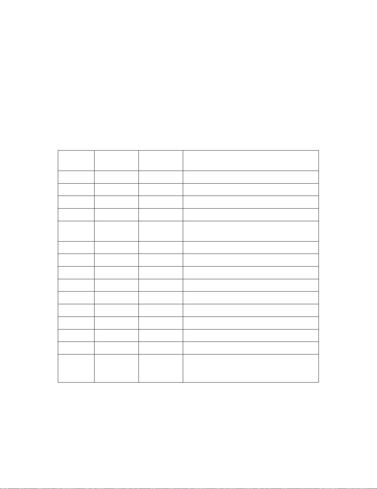
Conversion Kit, Part No. 124918-( ) Contents
Item No. Part No.
Kit Dash
Number
Description
1 201258 All Low NOx Burner Assembly
2 124715 All 5/16-18 x 1-3/4” Long Studs (Qty=6)
3 124867 -1, -2 Only Staged Ignition Assembly
4 124983 -3, -4 Only Staged Ignition Assembly
5 124991 All Low NOx Air/Fuel Valve Gas Plate
Assembly
6 161625 All Low NOx Air/Fuel Valve Butterfly
7 124803 All Low NOx Gas Regulator Plated Spring
8 124870 All Solenoid Valve Harness
9 124839 All Low NOx Combustion Chamber Liner
10 124570 All Low NOx Igniter Assembly
11 124837 All Low NOx Flame Rod Assembly
12 124919 All Low NOx Conversion Labels Sheet
13 124797 -1, -3 Only Low NOx Heater Specs. Label
14 124798 -2, -4 Only Low NOx Boiler Specs. Label
15 GF-111LN
or
GF-109LN
-1 Only
or
-2 Only
Low NOx Heater O & M Manual
or
Low NOx Boiler O & M Manual
2
Page 3

1.3 Tools and Test Equipment Required
The required tools and test equipment are listed in paragraphs 1.3.1 and 1.3.2 respectively.
1.3.1 Tools
The following tools are required to perform the conversion procedures specified in this Service
Bulletin:
• Wrenches: 3/16”, 7/16”, 1/2”, two 9/16”, 5/8”, 11/16”, 15/16”
• Vise-Grip Pliers
• Flat Tip Screwdriver, 1/2” - Inch Blade
• Phillips Head Screwdriver, No. 3
• AERCO Differential Gas Pressure Regulator Adjustment Tool, Part No. GM-122643
1.3.2 Test Equipment
Following installation of all Conversion Kit items, the following test equipment will be required to
perform combustion calibration of the modified KC1000 Boiler or Water Heater using the applicable
Operation & Maintenance Manual:
• Digital Combustion Analyzer – Oxygen accuracy to ±0.5 %, carbon monoxide and NOx
resolution to 1 ppm.
• One 16” W.C. Manometer and plastic tubing
• One 1/4 inch and two 1/8 inch NPT-to-barbed fittings for use with manometers
WARNING
HIGH VOLTAGE OF 120 VAC IS USED IN KC1000 SYSTEMS. USE
EXTREME CARE WHEN ACCESSING CIRCUITS AND ELECTRICAL
CONNECTIONS WITHIN THE EQUIPMENT. SERIOUS PERSONAL INJURY
OR DEATH MAY OCCUR IF THIS WARNING IS NOT OBSERVED.
2. EQUIPMENT REMOVAL
The locations of the major items to be removed from the KC1000 are shown in Figure 1. These items
include the existing Burner Assembly, Combustion Chamber Liner, Gas Inlet Pipe and the Air/Fuel
Valve. The existing Burner and Combustion Chamber Liner will be replaced with new assemblies
provided in the Conversion Kit. The Air Fuel Valve will be modified using the applicable procedures in
Section 3.
3
Page 4
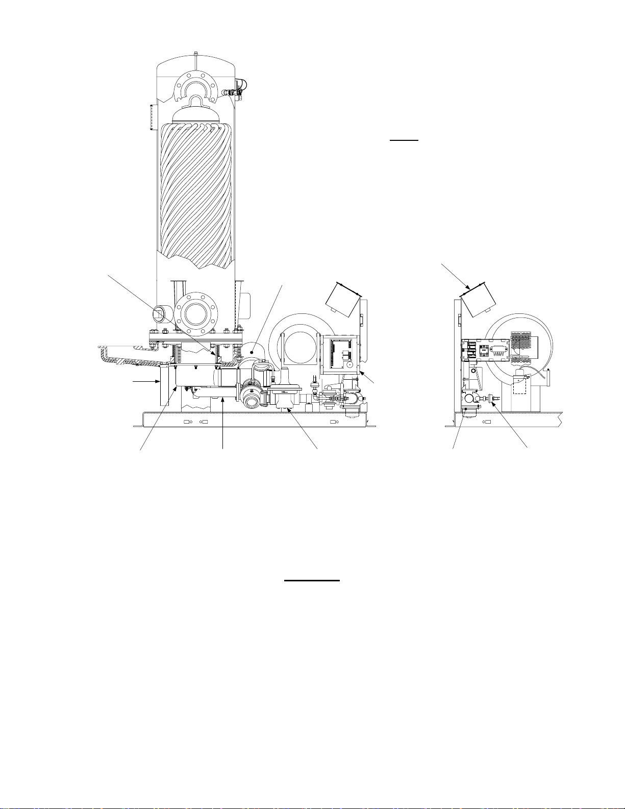
NOTE
ILLUSTRATION SHOWS KC BOILER WITH
COVERS REMOVED. THE LOCATIONS OF
THE AFFECTED ITEMS ARE IDENTICAL FOR
BOTH KC BOILERS AND WATER HEATERS
COMBUSTION
CHAMBER
LINER
CONDENSATE
DRAIN TUBE
BURNER
ASSEMBLY
CONTROL
AIR/FUEL
VALVE
I/O
BOX
GAS INLET
PIPE
DIFFERENTIAL
GAS PRESSURE
REGULATOR
Figure 1. KC1000 Component Locations
BOX
SSOV
LOW GAS
PRESSURE
SWITCH
Removal of the required items is accomplished as follows:
CAUTION
DO NOT DISCARD ANY OF THE REMOVED PARTS OR ASSEMBLIES
UNLESS IT IS SPECIFICALLY INDICATED THAT THEY WILL NO LONGER
BE USED. IT IS RECOMMENDED THAT ALL REQUIRED ITEMS BE
REMOVED AS INDICATED IN THE FOLLOWING STEPS PRIOR TO
PERFORMING ANY REPLACEMENT PROCEDURES IN SECTION 4.
1. Turn off the gas supply and disconnect AC power from the unit.
2. Remove the top and side sheet metal covers from the unit.
3. At the rear of the unit, disconnect the plastic tubing from the condensate cup to the drain.
4
Page 5
4. Remove the rear covers from the unit.
5. Remove the condensate cup from under the unit and disconnect the condensate drainage
tube from the exhaust manifold.
6. Disconnect the flame detector and igniter cable leads from the flame detector and igniter
contactor.
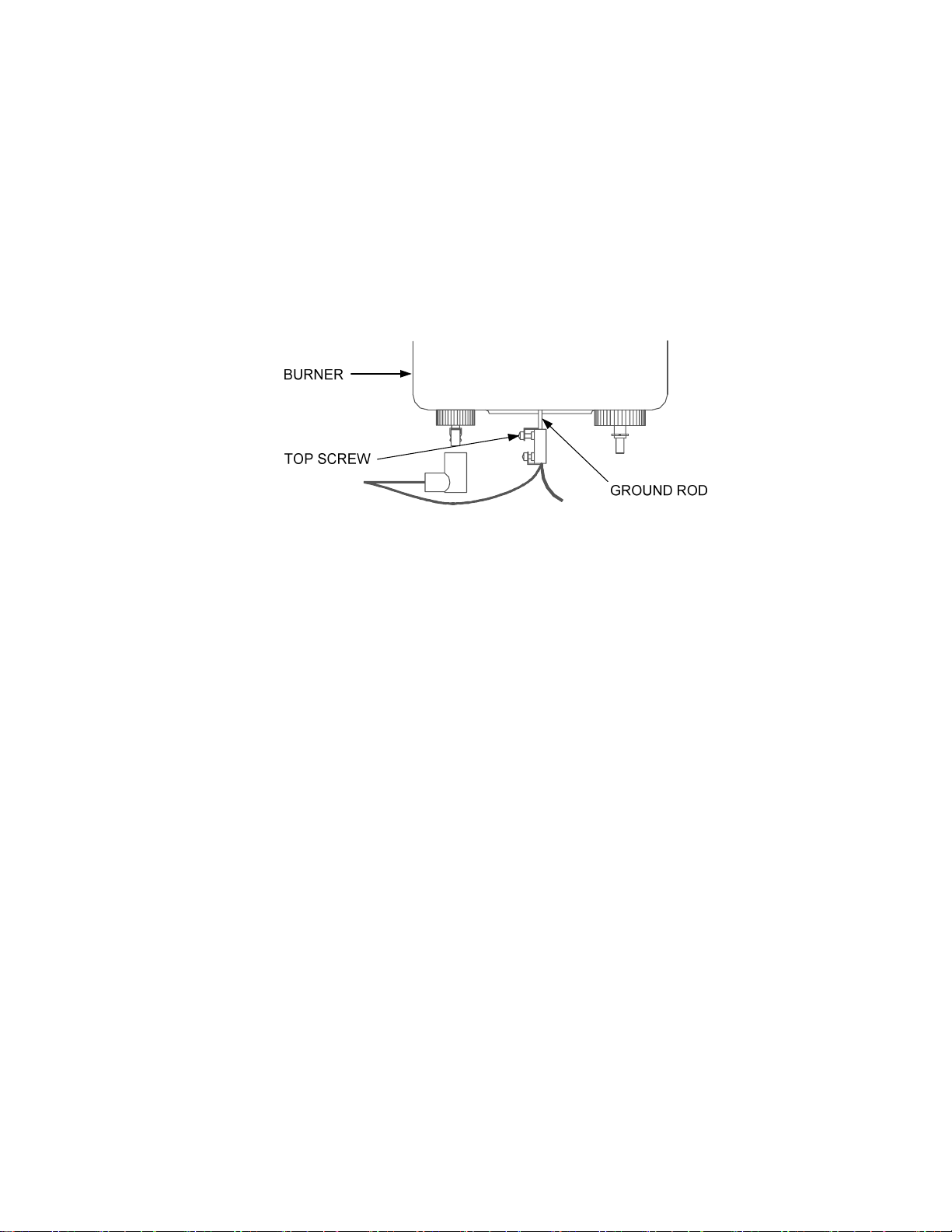
7. Remove the ground terminal connection from the Burner by loosening the top screw shown in
Figure 2. Slide the connector off the grounding rod.
Figure 2. Ground Terminal Location
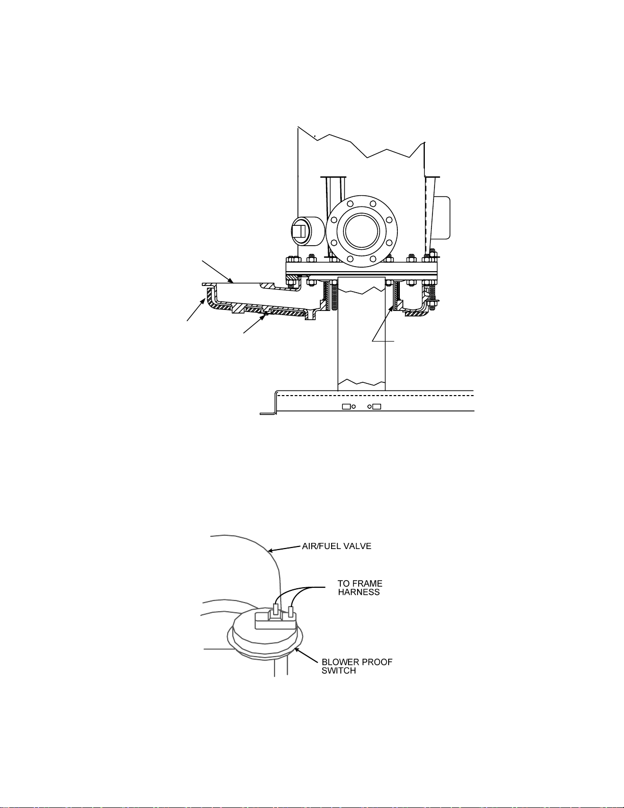
8. Using a 7/16 inch socket or open end wrench, remove the four 1/4 – 20 hex nuts on the gas
inlet pipe flange at the Burner. See Figure 3.
9. Using two 9/16 inch wrenches, remove the two 3/8” – 16 hex nuts and bolts on the gas inlet
pipe flange at the Air/Fuel Valve (Figure 3). Remove the gas inlet pipe and gaskets from the
unit.
10. Loosen the hose clamp on the Air/Fuel Valve side of the valve-to-burner air hose as shown in
Figure 3.
11. Using a 1/2 inch socket wrench, remove the six 5/16 – 18 hex nuts supporting the existing
Burner Assembly (Figure 3).
12. Lower the Burner Assembly while sliding the valve-to-burner air hose off the Air/Fuel Valve.
Completely remove the Burner from the rear of the unit.
13. Loosen the hose clamp on the removed Burner Assembly inlet and slide the valve-to-burner
air hose off the Burner. Retain the hose and clamp. These items will be reinstalled in Section
4. The removed Burner Assembly will be replaced with the new Low NOx Burner provided in
the Conversion Kit.
5
Page 6
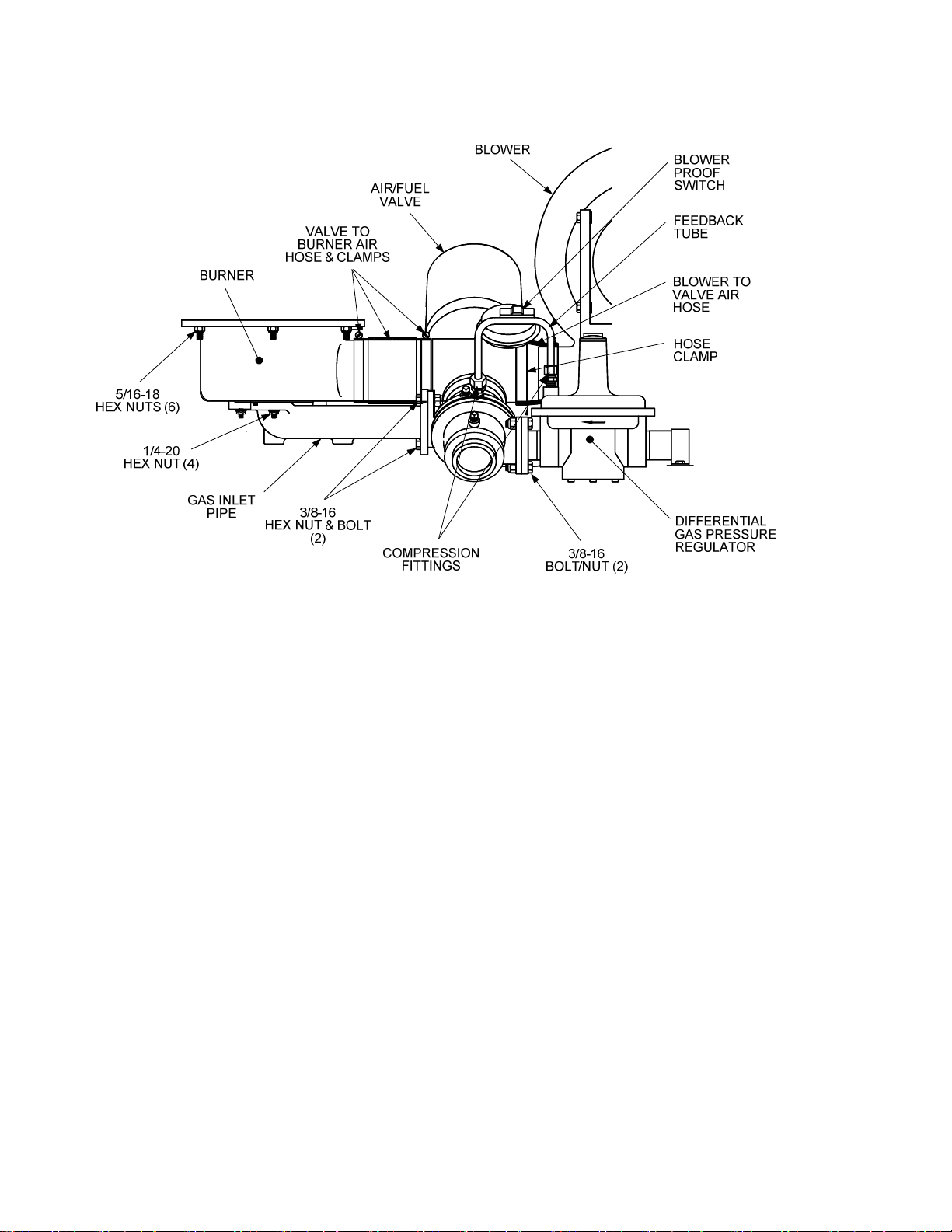
Figure 3. Burner & Air/Fuel Valve Removal
14. Remove the 8-inch Combustion Chamber Liner from the Heat Exchanger (Figure 4). Since
this liner will be replaced, It may be cut or broken to simplify removal.
NOTE
If difficulty is encountered during removal of the 5/16-18 studs, it may be
necessary to “Double-Nut” the studs to simplify the removal process.
15. Using vise-grip pliers, remove the six 5/16–18 x 1-1/2” long studs used to secure the removed
Burner Assembly to the Exhaust Manifold. These studs will be replaced with 1-3/4” studs
provided in the Conversion Kit.
16. Disconnect the Air/Fuel Valve wiring harness from the Control Box.
17. Disconnect the two wire leads from the Blower Proof Switch shown in Figure 5.
18. Loosen the hose clamp on the Air/Fuel Valve inlet side of the blower-to-valve air hose shown
in Figure 3.
19. Using an 11/16 inch wrench, loosen the two compression fittings securing the feedback tube to
the Air/Fuel Valve and Differential Pressure Regulator shown in Figure 3.
20. Using two 9/16 inch wrenches, remove the two 3/8–16 bolts and hex nuts securing the Air Fuel
Valve to the Differential Pressure Regulator (Figure 3).
6
Page 7
EXHAUST
MANIFOLD
INSULATION
1/4-20 SCREW &
FENDER WASHER
(3 PLACES)
COMBUSTION
CHAMBER LINER
Figure 4. KC1000 With Burner & Air/Fuel Valve Removed
Figure 5. Blower Proof Switch
7
Page 8

CAUTION
USE CARE WHEN REMOVING THE AIR/FUEL VALVE TO AVOID
DAMAGING OR LOSING THE FLANGE O-RING.
21. Completely remove the Air/Fuel Valve from the unit. This assembly will be modified in
Section 3.
22. Remove the Exhaust Manifold insulation (Figure 4) by removing the three 1/4-20 screws and
fender washers securing it in place.
NOTE
Current KC1000 units are equipped with Siemens Safety Shutoff Valves
(SSOVs). However, some earlier units may be equipped with Honeywell
SSOVs. The mounting location of the Low Pressure Gas Switch will differ
slightly, depending on the SSOV installed. Refer to Figure 6 (Siemens) or
Figure 7 (Honeywell) for the appropriate SSOV installed.
23. Next, refer to Figure 6 (Siemens SSOV) or Figure 7 (Honeywell SSOV) to locate the Low
Pressure Gas Switch on the right side of the unit. Disconnect the two wire leads from the
switch.
24. For Siemens SSOVs, the Low Pressure gas Switch is installed in the upstream SSOV port
using an NPT reducer. For Honeywell SSOVs, the Switch is installed directly in the gas supply
inlet pipe. Temporarily remove the Low Pressure Gas Switch as follows:
(a) For Siemens SSOVs, remove the switch (with NPT reducer attached) from the upstream
SSOV port using a 5/8” wrench.
(b) For Honeywell SSOVs, remove the switch from the tapped hole in the gas supply inlet
pipe using a 1/2” wrench.
The Low Pressure Gas Switch will be reinstalled in Section 4.
8
Page 9
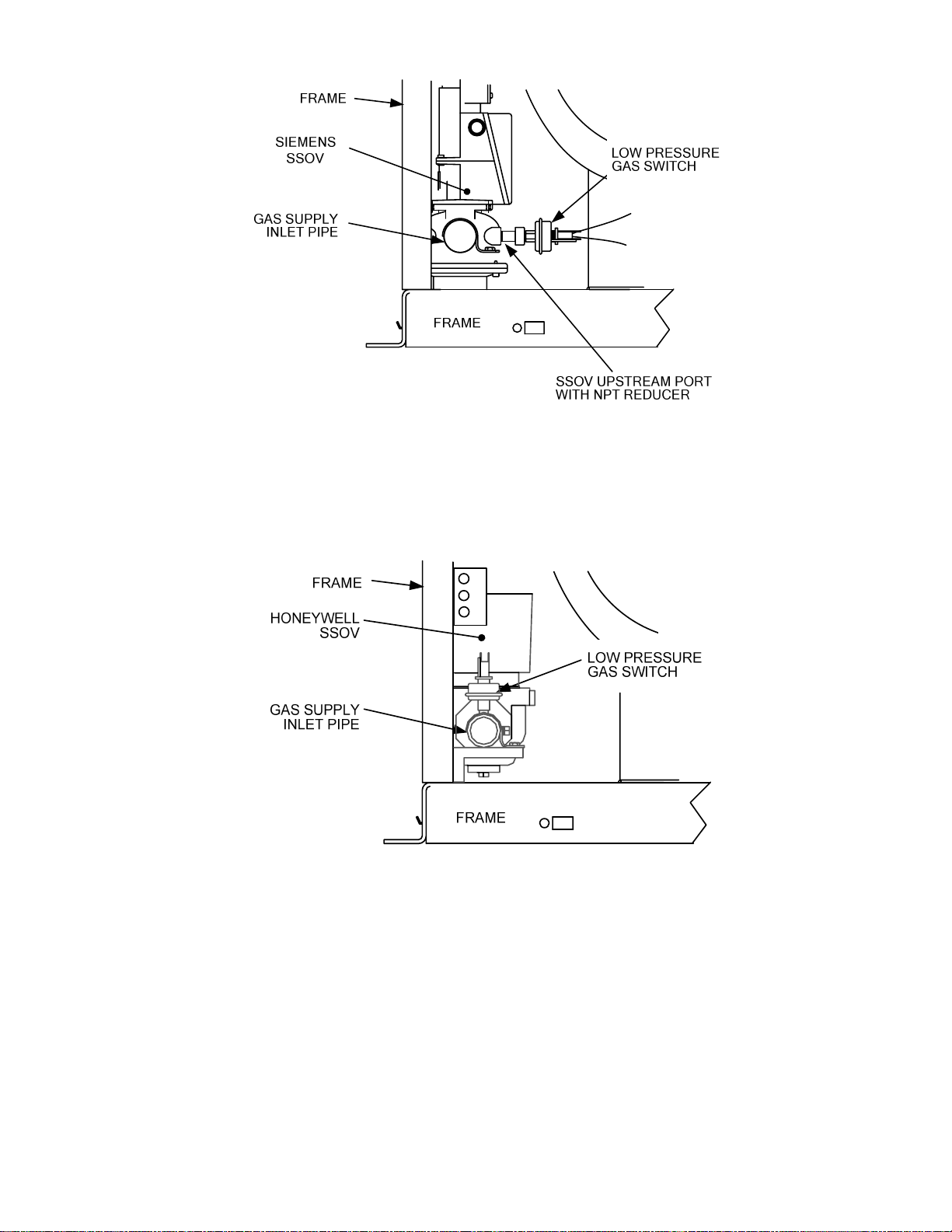
Figure 6. Low Pressure Gas Switch Location With Siemens SSOV Installed
Figure 7. Low Pressure Gas Switch Location With Honeywell SSOV Installed
25. This completes the equipment removal procedures for the KC Boiler or Water Heater. Proceed
to the Modification/Rework procedures in Section 3.
9
Page 10

3. EQUIPMENT MODIFICATION/REWORK
The equipment items to be modified are the Air/Fuel Valve and Differential Gas Pressure Regulator.
The Air/Fuel Valve was removed from the unit in Section 2 of this Service Bulletin. The Differential
Gas Pressure Regulator can be modified in place without removal. The modification procedures for
these items are presented in paragraphs 3.1 and 3.2 which follow.
3.1 Air/Fuel Valve Modification
The modifications to be made to the Air/Fuel Valve consist of replacing the lower gas plate and the air
valve butterfly with the replacement items contained in the Conversion Kit. Place the Air/Fuel Valve
on a workbench and proceed as follows:
1. Rotate the Air/Fuel Valve butterfly so that the valve is in the fully closed position.
2. Using a 7/16 inch socket or wrench, remove the four 1/4-20 hex head machine screws
securing the lower portion of the Air/Fuel Valve body to upper valve body as shown in
Figure 8.
CAUTION
DO NOT ROTATE THE VALVE BUTTERFLY FROM THE FULLY CLOSED
POSITION AFTER SEPARATING THE UPPER AND LOWER VALVE BODY.
3. Separate the upper and lower portions of the valve body to access the gas plate as shown in
Figure 9.
4. Remove the existing gas plate with upper/lower O-rings from the Air/Fuel Valve.
5. Obtain the replacement low NOx gas plate and O-rings from the Conversion Kit. Apply O-ring
lube (Dow-Corning Compound #111, or equiv.) to the replacement O-rings and install them in
the grooves on the gas plate.(Figure 10).
6. Refer to the cut-away view in Figure 9. Ensure that the valve components are positioned as
shown in the upper valve body.
7. Position the low NOx gas plate so that the plate slot engages the locating pin in the upper
valve body (Figure 9). Also, ensure that the shutter stop pin (Figures 9 and 10) is facing the
upper portion of the valve body.
8. Apply LocTite No. 242 (Blue), or equivalent, to the threads of the four 1/4-20 hex head
machine screws removed in step 2. Reassemble and secure the lower and upper portions of
the valve body by alternately tightening the four 1/4-20 machine screws.
10
Page 11
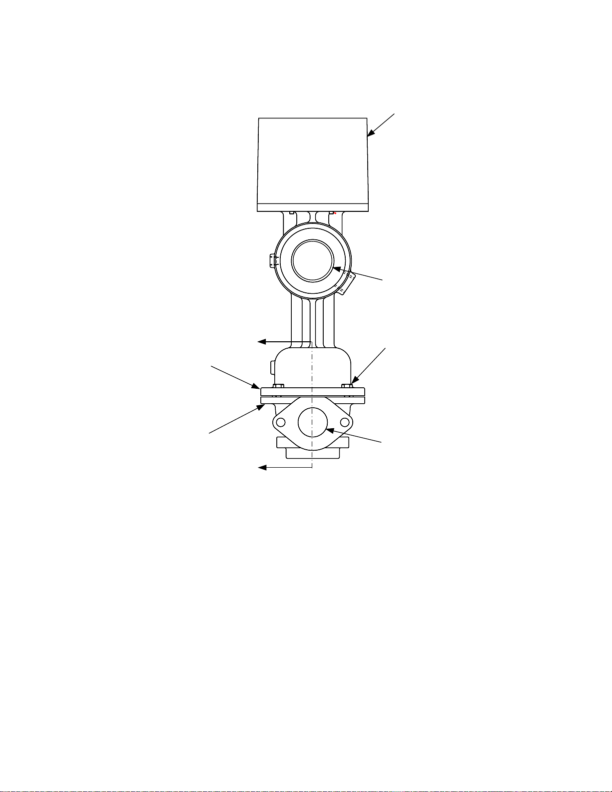
STEPPER
MOTOR
COVER
AIR INLET
VALVE BODY
(UPPER)
VALVE BODY
(LOWER)
A
(SEE FIGURE 9)
A
1/4-20 HEX HEAD
SCREWS (4)
GAS INLET
Figure 8. Air/Fuel Valve Modification
11
Page 12
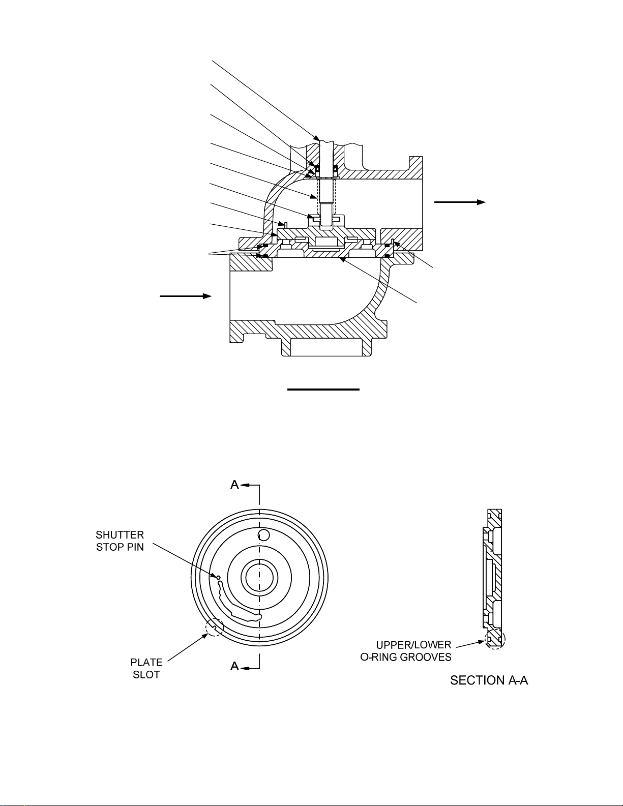
VALVE SHAFT
SPRING RING-
SHAFT SEAL
SHAFT SEAL-
BACKUP WASHER
RETAINING RING
PRE-LOAD SPRING
SHAFT DRIVE PIN
SHUTTER STOP PIN
GAS VALVE
SHUTTER
GAS PLATE
O-RINGS (2)
FUEL OUTLET
PLATE LOCATING
PIN
FUEL INLET
GAS PLATE
VIEW A - A
Figure 9. Air/Fuel Valve – Partial Cross-Sectional View
Figure 10. Low NOx Gas Plate
12
Page 13
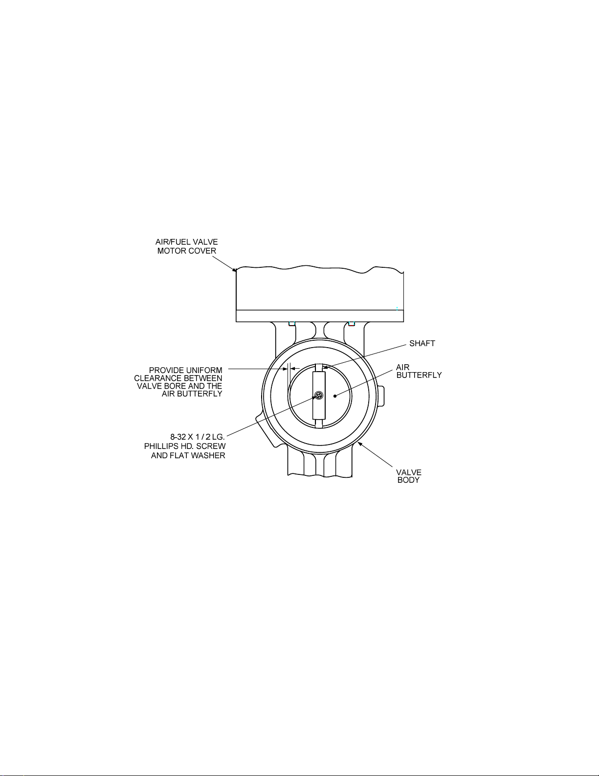
9. Next, remove the #8-32 screw securing the existing air butterfly to the Air/Fuel Valve shaft
(Figure 11) and remove the butterfly.
10. Apply a small amount of LocTite No. 222 (purple) to the #8-32 screw threads and install the
new air butterfly and flat washer provided in the Conversion Kit onto the shaft. Center the
butterfly so that there is equal clearance between the valve bore and the edges of the butterfly.
11. Manually open and close the butterfly several times to ensure that it is properly positioned on
the shaft with equal clearances around the valve bore
12. This completes the Air/Fuel Valve modifications. The modified Air/Fuel Valve is now ready to
be reinstalled using the procedures in Section 4.
Figure 11. Air Butterfly Replacement
3.2 Differential Gas Pressure Regulator Modification
The modification to be made to the Differential Gas Pressure Regulator consist of removing the exist
spring and replacing it with the new plated spring provided in the Conversion Kit. Proceed as follows:
1. Remove the cap on the Differential Gas Pressure Regulator (Figure 12).
2. Remove the adjustment screw and the installed regulator spring from the Differential Gas
Pressure Regulator.
3. Install the replacement plated spring provided in the Conversion Kit.
13
Page 14

IMPORTANT
It is important that the adjustment screw be installed to a depth of 2 inches
from the top of the regulator housing. This will simplify combustion calibration
of the unit after all low NOx modifications are completed.
4. Replace the adjustment screw and rotate the screw clockwise to a depth of 2 inches from the
top of the regulator housing.
5. Replace the regulator cap and gasket and ensure that the cap is firmly secured. This
completes the modification of the Differential Gas Pressure Regulator.
REGULATOR CAP
CAP GASKET
ADJUSTMENT
SCREW
SPRING
(PARTIALLY
REMOVED)
DIFFERENTIAL GAS
PRESSURE REGULATOR
Figure 12. Differential Gas Pressure Regulator Modification
14
Page 15
4. EQUIPMENT REPLACEMENT & REINSTALLATION
The parts provided in the Low NOx Conversion Kit will differ slightly, depending on whether the
KC1000 is equipped with a Siemens SSOV (-1 or -2 Kit) or a Honeywell SSOV (-3 or -4 Kit). See
paragraph 1.2 for kit contents. Following removal and/or modification of all the required parts and
assemblies, replace or reinstall these items as follows:
NOTE
Unless otherwise specified, the following steps apply to all KC1000 Boilers
and Water Heaters, regardless of the type of SSOV installed.
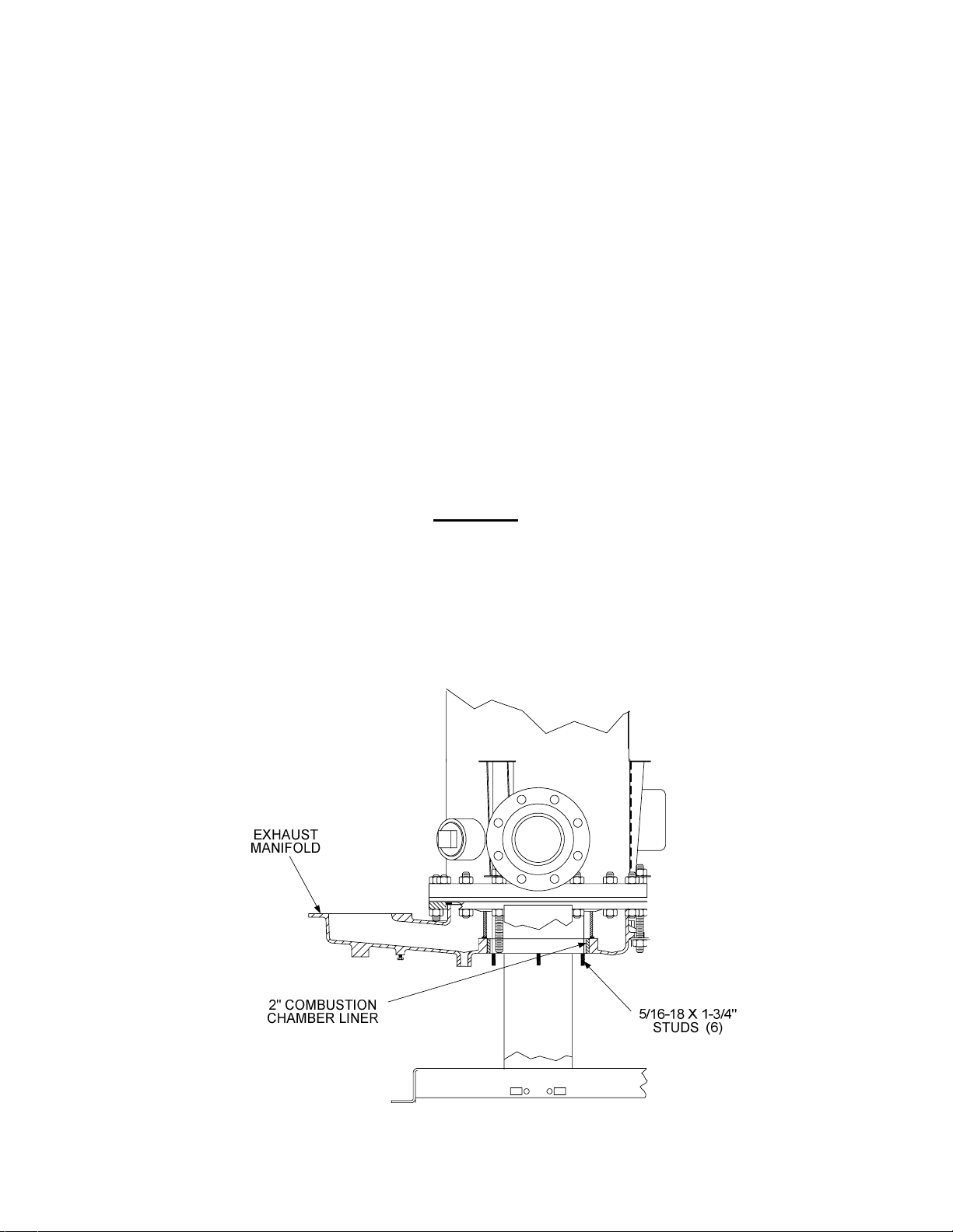
1. Install the six new 5/16”-18 x 1-3/4” studs provided in the Kit in the Exhaust Manifold as
follows:
(a) Apply LocTite 620 (or equivalent) to the manifold-end of the stud threads.
(b) Thread the ends of the studs into the tapped holes in the bottom of the Exhaust Manifold
as shown in Figure 13. Ensure that they are fully inserted and secure. These studs will
be used to secure the new Low NOx Burner to the manifold.
CAUTION
THE EXHAUST MANIFOLD OPENING IS SLIGHTLY TAPERED. THEREFORE, USE CARE WHEN INSTALLING THE COMBUSTION CHAMBER
LINER TO AVOID DAMAGE.
2. Position and install the new 2 inch Combustion Chamber Liner using the steps shown in
Figure 14. Position the Liner so it is flush with the bottom of the Exhaust Manifold (Figure 13)
Figure 13. Exhaust Manifold Studs and Combustion Chamber Liner Location
15
Page 16

Figure 14. Installation of Combustion Chamber Liner
NOTE
The next item to be installed is the new Low NOx Burner Assembly provided
in the Conversion Kit. To simplify installation and avoid component damage, it
will be necessary to temporarily remove several components from the Low
NOx Burner Assembly.
3. Remove the new Low NOx Burner from the Conversion Kit. Refer to Figure 15 and temporarily
remove the following components and assemblies from the Low NOx Burner:
(a) Remove the Igniter and Flame Detector Assemblies.
(b) Remove the 1/8” NPT nipple and the 1/4” O.D. tubing from the Burner Shell.
(c) Loosen the top screw on the two-way connector and slide it off the ground stud.
(d) Remove the 10-32 hex nut from the ground stud.
(e) Remove the two bolts securing the Burner Head to the Shell.
(f) Separate the Burner Head from the Burner Shell.
(g) Proceed to step 4.
16
Page 17

Figure 15. Low NOx Burner Components
17
Page 18

4. Due to space limitations, the new Low NOx Burner Head and Shell must be temporarily
separated as described in the previous step and installed as follows:
(a) First, insert the Burner Head inside the Heat Exchanger.
(b) While hold the Head in the raised position, place the Fiber Frax Gasket and Burner Shell
under the unit.
(c) Lower the Burner Head and align it so that the ground stud shown in Figure 16 is aligned
with the hole in the Shell flange. Also, ensure that the Shell air inlet is positioned as
shown.
(d) Raise the complete Low NOx Burner Assembly and secure it to the Heat Exchanger studs
using the six 5/16-18 hex nuts removed from the old burner.
(e) Next, install the 1/4” O.D. tube and 1/8” NPT nipple (3” long) as shown in Figure 17.
Ensure that the 1/4” tube is inserted into the staged ignition orifice piece. Thread the
nipple into the tapped hole in the bottom of the Burner Shell.
(f) Refer to Figure 19 and remove the 1/8” street elbow from the outlet end
of the Staged
Ignition Assembly provided in the Conversion Kit.
NOTE
The Staged Ignition Assembly part number provided in the Low NOx
Conversion Kit will depend on whether the unit being converted is equipped
with a Siemens or a Honeywell SSOV. Kits 124918-1 and -2 contain Staged
Ignition Assembly part no. 124867 for use with Siemens SSOVs. Kits 1249183 and -4 contain Staged Ignition Assembly part no. 124983 for use with
Honeywell SSOVs.
(g) Attach the street elbow to the 3” nipple and securely tighten the nipple to the Burner Shell.
18
Page 19

IGNITION
TRANSFORMER
EXHAUST
MANIFOLD
2" COMBUSTION
CHAMBER LINER
5/16-18 X 1-3/4"
STUDS (6)
STAGED IGNITION
ORIFICE PIECE
GROUND
STUD
Figure 16. Low NOx Burner Installation
BURNER
HEAD
FIBER FRAX
GASKET
AIR INLET
BURNER SHELL
19
Page 20

Figure 17. Installation of Staged Ignition Tube and Nipple
5. Reinstall the Exhaust Manifold insulation (Figure 4) using three 1/4-20 screws and fender
washers.
6. Reinstall the modified Air/Fuel Valve (Figure 18) as follows:
(a) Connect the blower-to-valve air hose and clamp at the Air/Fuel Valve inlet as shown in
Figure 18. Do Not tighten the hose clamp at this time.
(b) Ensure that the flange O-ring is installed between the Air/Fuel Valve gas inlet flange and
the Differential Gas Pressure Regulator outlet flange.
(c) Using two 9/16” wrenches, secure the Air/Fuel Valve to the Differential Gas Pressure
Regulator with two 3/8-16 bolts and hex nuts.
(d) Tighten the hose clamp on the blower-to-valve air hose at the Air/Fuel Valve inlet.
(e) Using an 11/16” wrench, secure the feedback tube between the Air/Fuel Valve and
Regulator by tightening the two compression fittings (Figure 18).
(f) Reconnect the two wire leads to the Blower Proof Switch.
(g) Reconnect the Air/Fuel Valve wiring harness to the Control Box.
7. Install the Gas Inlet Pipe (Figure 18) between the Air Fuel Valve gas outlet and the Low NOx
Burner gas inlet as follows:
(a) Insert flange O-rings in the inlet and outlet sides of the gas pipe.
(b) Position the Gas Inlet Pipe so it is aligned with the 1/4-20 studs on the Burner and the
Air/Fuel Valve gas outlet flange.
20
Page 21

(c) Secure the Gas Inlet Pipe to the Air/Fuel Valve with two 3/8-16 bolts and hex nuts.
(d) Secure the Pipe to the Burner with four 1/4-20 hex nuts.
(e) Reinstall the valve-to-burner air hose and clamps between the Air/Fuel Valve outlet and
Burner inlet. Tighten both clamps.
NOTE
Figure 18 shows the installation details for both the modified Air/Fuel Valve
and the Gas Inlet Pipe. Install these items in the order specified in steps 6
and 7.
Figure 18. Air/Fuel Valve and Gas Inlet Pipe Installation
The next item to be installed is the new Staged Ignition Assembly shown in Figure 19. As this
8.
Figure shows, there are two versions of this assembly; one for use with Siemens SSOVs (part
no. 124867) and one for use with Honeywell SSOVs (part no. 124983). Mechanically, the
outlet side of both Staged Ignition Assembly models connect to the Low NOx Burner.
However, the inlet side connections of Staged Ignition Assembly models differ as follows:
• Staged Ignition Assembly 124867 (used with Siemens SSOVs) inlet side connects to the
downstream port directly on the Siemens SSOV.
• Staged Ignition Assembly 124983 (used with Honeywell SSOVs) inlet side connects to the
port on the gas cock located downstream of the Honeywell SSOV.
Electrically, the solenoid valve on each of these assemblies is connected to the KC wiring
harness power leads going to the ignition transformer. The mechanical connections are
provided in steps 9, 10 and 11. The electrical connections are provided in step 13.
21
Page 22

Figure 19. Staged Ignition Assemblies – Part No. 124867 & 124983
22
Page 23

NOTE
The 1/8” street elbow shown in Figure 19 was previously removed in step 4(f)
and attached to the 3” nipple on the Low NOx Burner Shell.
9. The outlet side connection for the Staged Ignition Assembly is the same regardless which type
of SSOV (Siemens or Honeywell) is installed on the KC1000. Proceed as follows:
(a) Loosen the 1/4“ NPT union on the Staged Ignition Assembly (Figure 19) provided in the kit
and separate the 9” nipple and 1/4” to 1/8” reducing coupling from the assembly.
(b) Connect the reducing coupling to the 1/8” street elbow already attached to the Low NOx
Burner (Figure 20).
GROUND
CONNECTOR
1/8" NPT
NIPPLE
(3" LONG)
STREET
ELBOW
REDUCING
COUPLING
1/4" NPT NIPPLE
GAS INLET
(9" LONG)
PIPE
Figure 20. Staged Ignition Assembly Outlet Side Connection
10. The inlet side connection for the Staged Ignition Assembly depends on which type of SSOV
(Siemens or Honeywell) is installed in the KC1000. Proceed as follows:
(a) Refer to Figure 19. For the Staged Ignition Assembly provided in the kit, disconnect the
1/2” flex gas hose at the inlet side from the 1/2” to 1/4” reducing coupling shown in Figure
19 for the applicable assembly.
23
Page 24

(b) If the KC1000 is equipped with a Siemens SSOV, remove the 1/4” NPT plug from the
downstream port on the SSOV. Connect the inlet side (flex gas hose and nipple) of the
Staged Ignition Assembly (part no. 124867) to this 1/4” NPT port as shown in Figure 21.
LOW PRESSURE
GAS SWITCH WITH
NPT REDUCER
BLOWER
GAS
INLET
SSOV
STAGED IGNITION ASSY
FLEX GAS HOSE
CONNECT TO 1/4" NPT
DOWNSTREAM PORT
KC1000 PARTIAL TOP VIEW
Figure 21. Staged Ignition Assembly Inlet Connection For Siemens SSOV
(c) For a Honeywell SSOV, remove the 1/8” plug from the inboard side of the gas cock shown
in Figure 22. Connect the inlet side of the Staged Ignition Assembly (part no. 124983)
containing the 5” long 1/8” NPT nipple to the gas cock port.
24
Page 25

Figure 22 Staged Ignition Assembly Inlet Connection For Honeywell SSOV
11. After the Staged Ignition outlet and inlet connections are completed, reconnect the 1/4“ NPT
union at the Burner side (outlet) and the flex gas hose at the SSOV side (inlet) to the
remaining assembly components (Figure 19).
12. The Solenoid Valve on the Staged Ignition Assembly is electrically connected to the Ignition
Transformer power leads using the 2-Wire Solenoid Valve Harness provided in the Conversion
Kit (Figure 23). Proceed as follows:
(a) Connect the two Solenoid Valve power leads to the FASTON terminals of the wiring
harness.
(b) Remove the cover on the Ignition Transformer.
(c) Refer to Figure 23 and remove the two wire nuts connecting power leads 140 and 141 to
the Ignition Transformer. Connect the two stripped Solenoid harness leads to power leads
140 and 141 and the Transformer leads as shown.
(d) Resecure the wiring connections using the wire nuts.
(e) Replace the cover on the Ignition Transformer.
(f) Connect the Solenoid Valve Ground lead to the Ground connector on the Low NOx Burner
Shell flange (Figure 20).
25
Page 26

13. Next, install the Igniter and Flame Detector in the Low NOx Burner (Figure 24) as follows:
(a) Prior to installing the Igniter in the Low NOx Burner, a conductive
anti-seize compound
MUST be applied to the Igniter threads.
(b) Install the Igniter at the location shown in Figure 24. Do Not over-tighten.
(c) Connect the Igniter cable from the Ignition Transformer.
(d) Install the Flame Detector at the location shown in Figure 24. Do Not over-tighten.
(e) Reconnect the Flame Detector lead.
Figure 23. Solenoid Valve Wiring Harness and Connections
26
Page 27

Figure 24. Igniter and Flame Detector Installation
14. Reinstall the Low Pressure Gas Switch shown in Figure 6 (Siemens SSOV) or Figure 7
(Honeywell SSOV). Reconnect the two switch wire leads. There is no polarity to observe
when reconnecting these leads.
15. Refer to Figure 25 and install the condensate drain components at the rear of the unit as
follows:
(a) Attach the 1-3/4” O.D. condensate drain hose to the exhaust manifold (Figure 25) and
insert the hose into the condensate cup. Allow the cup to rest on the floor directly beneath
the condensate drain.
(b) Connect a length of 3/4” tubing to the condensate cup drain tube and route it to a floor
drain.
27
Page 28
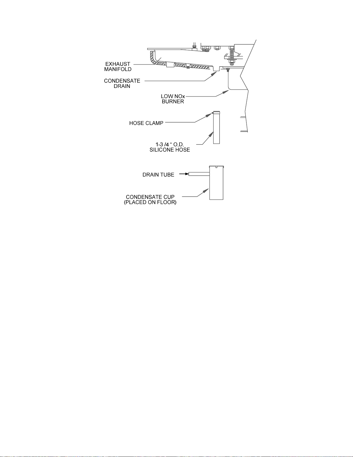
Figure 25. Condensate Drain Assembly Location
16. Prior to proceeding to the next step, check to ensure that the igniter, flame detector and
ground leads are secure on the Low NOx Burner. Also, check to ensure that the ball valve in
the Staged Ignition Assembly (Figure 19) is in the open position.
17. Replace the rear covers, top cover and side panels on the unit.
18. Attach the appropriate Low NOx labels to the unit as follows:
(a) Attach the SCAQMD/TCEQ LOW NOx label to the front of the unit directly beneath the
“For parts replacement …” label as shown in Figure 26.
(b) Attach the appropriate Heater or Boiler UL Label and Specification Label to the front of the
unit (Figure 26).
(c) On the left side of the unit, attach the “Igniter & Flame Detector Replacement” label over
the currently installed replacement label at the location shown in Figure 27.
28
Page 29

Aerco KC Gas Fir ed
U
L
GAS-FIRED BOILER
FOR USE WITH INTEGRAL
CONTROLS
INTENDED FOR USE WITH UL LISTED SPECIAL GAS VENT
FOR USE WITH CATEGORY III OR IV GAS APPLIANCES WITH
MANUFACTURERS INSTRUCTIONS FOR F URTHER VENTING
DETAILS.
For parts assistan ce during norm al business ho urs
call your loca l sales repres entative or . ..
Aerco International at 1-800-526 -0288.
Hot Water Boiler
Aerco KC Gas Fired Hot Water Boiler
INVERSE EFFICIENCY CURVE
99%
THIS PRODUCT COMPLIES WITH NOx EMISSIONS
STANDARDS OUTLINED IN SOUT H COAST AIR
QUALITY MANAGEMENT DISTRICT ( SCAQMD )
RULE 1146.2 AND TEXAS COMMISION ON
ENVIRONMENTAL QUALI TY ( TCEQ ), TITLE 30,
CHAPTER 117, RULE 117.465, WHEN INSTALLED
AND OPERATED IN ACCORDANCE WITH AERCO
INSTALLATION, OPERATION, & MAINTENANCE
INSTRUCTIONS.
INTERNATIONAL INC.
86%
FIRING RATE
7%
Specifications
Net Input...................................................................
Net Output.................................................................
ASME Maximum Working Pressure............................
Electrical Requirements............................................
Maximum Water Flow................................................
Water Pressure
Drop..................................................
OR
Aerco KC Gas Fired Commercial Water Heater
Recovery Capacity
Temp. Rise (F)
60 70
80 90
GPH
15941860
Specifications
Net Input………………………………………….
Net Output………………………………………….
ASME Maximum Working Pressure...............
Electrical Requirements………………………..
Standby Power Consumption........................
Adjustable Control Range……………………...
Maximum Continuous Water Flow.............................
Water Pressure Drop………………………....
Water Volum e……………… …………………...
Gas Pressure Requirements..........................
1,000,000 BTU/Hr
860,000 to 930,000 BTU/Hr
150 PSIG @ 250F
120/1/60 20 AMP
50F to 220F
25 GPM
150 GPM
0.1 psi @ 100 GPM
23 gallons
9.5" WC min. @ full load
14" WC maximum static
100 110
111612401395
1014
1,000,000 BTU/Hr
930,000 BTU/Hr
160 PSIG @ 210F
120/1/60 20 AMP
40 watts
100F to 195F
30 GPM
0.7 psi @ 20 GPM
23 gallons
9.5" WC min. @ full load
14" WC maximu m stati c
100%
120
930
BOILER
140
130
797
859
HEATER
PARTIAL FRONT VIEW
Figure 26. Low NOx Labels – Front View
29
Page 30

Figure 27. Low NOx Labels – Side View
19. This completes replacement or reinstallation of all required parts and assemblies. Proceed to
Section 5 - Post-Installation Setup and Calibration.
30
Page 31

5. POST-INSTALLATION SETUP AND CALIBRATION
Following installation of all Low NOx Conversion Kit items, it will be necessary to adjust several
operating parameters using the unit’s Control System menus. In addition, combustion calibration
procedures MUST be performed to ensure Low NOx compliance, prior to placing the unit into service.
The procedures in this section are divided into the following main categories:
• Low NOx Operating Parameter Menu Changes
• Combustion Calibration Setup
• Combustion Calibration Procedures for Units With C-More or Modular Control Systems
• Combustion Calibration Procedures for Units With Digital (CCC) Control Systems
• Unit Reassembly
These procedures are provided in paragraphs 5.1 through 5.5 respectively. For more detailed
information on the operation of your KC1000 unit, refer to the applicable Operation & Maintenance
Manual for the installed Control System as follows:
Unit
KC1000 Boiler GF-109LN GF-106 GF-102
KC1000 Heater GF-111LN GF-105 GF-101
C-More Control
System
Modular Control
System
Digital (CCC) Control
System
NOTE
If the KC1000 is equipped with an older style Digital (CCC) Control System,
no menu changes are required.
5.1 Control System Menu Changes for Low NOx Operation
If the KC1000 is equipped with either a C-More or Modular Control System, several menu changes
may need to be made to ensure Low NOx compliance. These changes will depend on which type of
control system is installed and whether the unit is a boiler or water heater.
5.1.1 Post-Purge Timeout For C-More Control System
If the unit is equipped with a C-More Control System, adjust the Post-Purge Timer in the Factory
Menu to 10 seconds as follows:
1. Apply external AC power to the unit.
2. Set the Control Box ON/OFF switch to OFF.
3. Access the Password entry in the Setup menu.
4. Enter and store the Factory Password (2807). Password 3 will be displayed indicating that the
valid Factory password has been entered.
5. Next, scroll through the Factory Menu until Post Purge Timer is displayed.
6. Set the Post Purge Timer menu option to 10 sec. and store the entry.
31
Page 32

7. This completes the Post Purge Timer menu setting.
8. If the unit is a Water Heater, go directly to paragraph 5.1.2 (Breakpoints) before the entered
Factory Password times out (after 1 hour). If the unit is a Boiler, no further menu changes are
required.
NOTE
The Breakpoint Adjustment procedures specified in paragraph 5.1.2 apply
only to KC1000 Water Heaters containing either a C-More or Modular Control
System.
5.1.2 Water Heater Breakpoint Adjustments
The water heater breakpoint settings for a Low NOx KC1000 are different than the breakpoints for a
standard unit. Therefore, the appropriate menu items must be adjusted. For C-More Control
Systems, the breakpoints are adjusted for fire rate increments of 10% using the Tuning Menu. For
Modular Control Systems, the breakpoints are adjusted using the Secondary Menu. Adjust the
breakpoints to the values shown in the following Table for the firing rates shown:
IMPORTANT
Prior to adjusting the breakpoint settings shown in the following Table, ensure
that the Water Heater active setpoint is set to 130°F. Following completion of
the breakpoint adjustments, the active setpoint temperature can be readjusted
if necessary.
Water Heater Breakpoint Settings For Low NOx
Firing Rate
100% Breakpoint At 100% bp A 64°F
90% Breakpoint At 90% bp 0 63°F
80% Breakpoint At 80% bp 9 66°F
70% Breakpoint At 70% bp 8 74°F
60% Breakpoint At 60% bp 7 83°F
50% Breakpoint At 50% bp 6 93°F
40% Breakpoint At 40% bp 5 103°F
30% Breakpoint At 30% bp 4 112°F
20% Breakpoint At 20% bp 3 115°F
C-More Display
Modular
Display
Required
Breakpoint
10% Breakpoint At 10% bp 2 128°F
0% Breakpoint At 0% bp 1 135°F
32
Page 33

5.2 Combustion Calibration Setup
Prior to performing Combustion Calibration procedures in paragraph 5.3 or 5.4, the unit must be set
up as follows:
5.2.1 Installing The Supply Gas Manometer
1. Close the manual gas supply valve upstream of the unit.
2. Refer to Figure 28 and remove the 1/4” or 1/8” NPT pipe plug from the port on the inlet side of
the Siemens or Honeywell SSOV.
3. Install a barbed fitting into the pipe plug tapping.
4. Attach one end of a length of plastic tubing to the barbed fitting and one end to the 16" W.C.
manometer.
Figure 28. Installation of Supply Gas Manometer
5.2.2 Preparing the Flue Vent Probe Hole
1. If the unit has been installed using the recommended AL29-4C vent, there will be a 3/8” hole,
18” to 24” above the exhaust manifold. The outer vent section, that covers vent connections,
must be loosened and moved to uncover the hole (see Figure 29).
2. If so equipped, adjust the stop on the combustion analyzer probe so that it extends into the
flue gas flow without hitting the opposite wall of the flue. Do not insert the probe at this time.
33
Page 34

Figure 29. Analyzer Probe Hole Location
5.2.3 Installing The Differential Regulator Adjustment Tool
1. Remove the cap from the differential pressure regulator (see Figure 30).
2. Place the gasket from the regulator cap onto the regulator adjustment tool.
3. Prior to Installing the tools on the regulator, pull up the tool's screwdriver blade. Then, thread
the tool into the regulator.
4. Engage the tool’s screwdriver blade into the regulator’s adjustment screw slot.
Figure 30. Regulator Adjustment Tool Installation
34
Page 35

5.3 Combustion Calibration For Units With C-More or Modular Control Systems
The Combustion Calibration procedures for KC1000 Boilers or Water Heaters equipped with either CMore or Modular Control Systems are virtually identical. Using the following procedures will minimize
readjustment of combustion.
NOTE
For a review of the control panel operating procedures for the installed control
system, refer to Section 3 of the appropriate O & M Manual listed in paragraph
5.
1. Open the supply and return valves to the unit and ensure that the system pumps are running.
Open the gas supply valve(s) to the unit.
2. If a lockup style regulator is installed as a gas supply regulator, adjust the gas supply until a
reading of 12” W.C. static pressure is obtained.
3. Set the ON/OFF switch to the OFF position. Turn on AC power to the unit.
4. Set the unit to the Manual Mode.
5. Adjust the firing rate to 0%.
6. Set the ON/OFF switch to ON.
7. Change the firing rate to 25%. This will put the unit in the starting sequence.
NOTE
On initial start-up, or return to service from a fault condition, the unit will
remain at a 29% firing rate for two-minutes, although the control signal may
indicate a greater input.
8. Following the warm-up period, increase the firing rate in 20% increments while monitoring the
gas pressure after every increase. If gas pressure dips below 9.5” W.C. for FM gas trains and
9.9” for IRI gas trains at any input firing rate percentage, stop and raise the pressure. Once
100% is reached, adjust the gas pressure for 9.5” (FM) W.C. or 9.9” W.C. (IRI).
NOTE
If 9.5” W.C. for FM gas trains or 9.9” W.C. for IRI gas trains cannot be
obtained at the 100% firing rate, it will be necessary to stop calibration and
contact the local AERCO representative in your area. Running the unit on
insufficient gas pressure will void the warranty.
9. Once 9.5” W.C. or 9.9” W.C. is set at the 100% level change the firing rate to 30%. Insert the
combustion analyzer probe into the stack.
35
Page 36

NOTE
Always approach a firing rate percentage from the same direction, (i.e., 100%
to 30%, 30% to 20%, etc.). Whenever going to an increased firing rate from
below (i.e., 20% to 30%), first go above and then back down to the desired
firing rate. This is necessary due to hysteresis in the air/fuel stepper motor.
Hysteresis causes the air/fuel valve to stop in a slightly different position if the
firing rate percentage is approached from below or above. This results in a
difference in oxygen readings for the same firing rate percentage causing
unnecessary recalibration.
9. Allow enough time for the combustion analyzer to settle. Compare the measured oxygen level
to the oxygen range for intake air temperature in Table 1. Also, ensure that the carbon
monoxide (CO) and nitrogen oxide (NOx) readings do not exceed the values shown.
Table 1
Combustion Oxygen Levels for a 30% Firing Rate
Inlet Air
Temp
Oxygen
(±0.2%)
40°F 6.7 % <100 ppm <23.8 ppm
50°F 6.5 % <100 ppm <24.1 ppm
60°F 6.3 % <100 ppm <24.4 ppm
75°F 6.0 % <100 ppm <24.9 ppm
85°F 5.7 % <100 ppm <25.4 ppm
90°F 5.6 % <100 ppm <25.6 ppm
100°F 5.4 % <100 ppm <25.9 ppm
*Tabulated data are uncorrected ppm NOx values and will be less than or equal to 30 ppm of
NOx when corrected to 3% oxygen.
Carbon
Monoxide
*NOx
10. If the measured oxygen level, CO and NOx emissions are within the ranges shown in Table 1,
no adjustment is necessary. Proceed to step 16.
11. If the measured oxygen level is below the range in Table 1, rotate the differential regulator
adjustment tool counterclockwise 1/4 to 1/2 revolution to decrease gas flow.
12. Wait for the combustion analyzer to settle, then compare the new oxygen reading to Table 1.
Repeat adjustment until oxygen is within the specified range.
13. If the measured oxygen level is above the oxygen range in Table 1, rotate the differential
regulator adjustment tool clockwise 1/4 to 1/2 revolution to increase gas flow.
14. Wait for the analyzer reading to settle, then compare the new reading to Table 1. Repeat
adjustment until oxygen is within the specified range.
NOTE
Adjust only the differential regulator at 30% control signal; do not adjust the air
shutter.
15. Once the oxygen level is within the specified range at 30%, change the firing rate to 16%.
36
Page 37

16. Oxygen levels at the 16% firing rate should be as shown in Table 2. Also, ensure that the CO
and NOx readings do not exceed the values shown. No adjustment should be necessary.
Contact the Factory if the oxygen, CO or NOx levels are not within the specified ranges.
Table 2
Combustion Oxygen Levels for a 16% Firing Rate
Inlet Air
Temp
Oxygen
(± 0.2%)
40°F <10% <100 ppm <20 ppm
50°F <10% <100 ppm <20 ppm
60°F <10% <100 ppm <20 ppm
75°F <10% <100 ppm <20 ppm
85°F <10% <100 ppm <20 ppm
90°F <10% <100 ppm <20 ppm
100°F <10% <100 ppm <20 ppm
*Tabulated data are uncorrected ppm NOx values and will be less than or equal to 30 ppm of NOx
when corrected to 3% oxygen.
Carbon
Monoxide
*NOx
17. Change the firing rate to 100%. After the combustion analyzer has settled, compare the
measured oxygen level with the levels in Table 3.
18. If the measured oxygen reading is below the oxygen range in Table 3, loosen the two bolts
that secure the inlet air shutter to the unit using a 7/16” wrench (see Figure 31). Open the
shutter 1/4” to 1/2” to increase the oxygen level, then tighten the nuts.
19. Wait for the analyzer to settle then compare the new oxygen reading to Table 3. Repeat the
inlet air shutter adjustment until the oxygen is within the specified range. Also, ensure that the
CO and NOx emissions do not exceed the values shown. Firmly tighten the inlet air shutter
locking nuts when finished.
Table 3
Combustion Oxygen Levels for a 100% Firing Rate
Inlet Air
Temp
Oxygen
(±0.2%)
40°F 8.8 % <100 ppm <20.3 ppm
50°F 8.1 % <100 ppm <21.4 ppm
60°F 7.5 % <100 ppm <22.5 ppm
75°F 6.5 % <100 ppm <24.1 ppm
85°F 5.8 % <100 ppm <25.3 ppm
90°F 5.3 % <100 ppm <26.1 ppm
*Tabulated Data are uncorrected ppm NOx values and will be less than or equal to 30 ppm of
NOx when corrected to 3% oxygen.
100°F 4.8 % <100 ppm
Carbon
Monoxide
*NOx
37
Page 38

Figure 31. Air Shutter Locking Nut Location
NOTE
At 30% firing rate, adjust only the differential pressure regulator. At 100%
firing rate, adjust only the inlet air shutter.
20. If the measured oxygen reading is above the oxygen range in Table 3, loosen the two 7/16"
locking nuts securing the inlet air shutter. Close the air shutter 1/4” to 1/2” to decrease the
oxygen level and tighten the two nuts.
21. Allow the analyzer to settle then compare the new oxygen reading to Table 3.
22. Repeat the adjustment until the oxygen is within the specified range. Also, ensure that the CO
and NOx readings do not exceed the values shown. Firmly tighten the inlet air shutter locking
nuts when finished.
NOTE
Adjust the inlet air shutter only at 100% firing rate. Do not adjust the
differential pressure regulator.
23. Change the firing rate to 30%. Allow time for the combustion analyzer to settle. Check the
measured oxygen level, CO and NOx emissions to ensure that they are still within the ranges
shown in Table 1.
24. Continue these procedures until all oxygen levels are within the ranges specified in Tables 1, 2
and 3.
25. Record all readings on the AERCO start-up sheet provided with each unit. Proceed to
paragraph 5.5 when all natural gas combustion calibration procedures are completed.
38
Page 39

5.4 Combustion Calibration For Units With Digital (CCC) Control Systems
The Combustion Calibration procedures for KC1000 Boilers or Water Heaters equipped with older
style Digital (CCC) Control Systems differ from those used for C-More or Modular Control Systems.
The primary difference is that the combustion readings are checked at different low and mid-range fire
rates. In addition, the Control Panel display shows the manual fire rate in % for KC Boilers and in
Volts (1.0 to 5.0) for KC Water Heaters. Using the following procedures will minimize readjustment of
combustion.
NOTE
For a review of the control panel operating procedures for the installed control
system, refer to Section 3 of GF-101 (Water Heater) or GF-102 (Boiler).
1. Open the supply and return valves to the unit and ensure that the system pumps are running.
Open the gas supply valve(s) to the unit.
2. If a lockup style regulator is installed as a gas supply regulator, adjust the gas supply until a
reading of 12” W.C. static pressure is obtained.
3. Set the unit to the MANUAL mode.
4. With the display showing the Power Level, rotate the MANUAL adjustment to display 25%
(Boiler) or 2.0 volts (Water Heater).
5. Press the green ON button if the unit is not already ON.
NOTE
On initial start-up, or return to service from a fault condition, the unit will
remain at a 29% firing rate for two-minutes, although the control signal may
indicate a greater input.
In the following steps and Tables, firing rates for KC1000 Boilers are shown in
% and the corresponding firing rates for Water Heaters are shown in
parentheses in volts (V).
6. Following the warm-up period, increase the firing rate in 25% (1.0V) increments while
monitoring the gas pressure after every increase. If gas pressure dips below 9.5” W.C. for FM
gas trains and 9.9” for IRI gas trains at any input firing rate percentage, stop and raise the
pressure. Once 100% (5.0V) is reached, adjust the gas pressure for 9.5” (FM) W.C. or 9.9”
W.C. (IRI).
NOTE
If 9.5” W.C. for FM gas trains or 9.9” W.C. for IRI gas trains cannot be
obtained at the 100% firing rate, it will be necessary to stop calibration and
contact the local AERCO representative in your area. Running the unit on
insufficient gas pressure will void the warranty.
7. Once 9.5” W.C. or 9.9” W.C. is set at the 100% (5V) level, change the firing rate to 25%
(2.0V). Insert the combustion analyzer probe into the stack.
39
Page 40

NOTE
Always approach a firing rate percentage from the same direction, (i.e., 100%
to 25%, 25% to 20%, etc.). Whenever going to an increased firing rate from
below (i.e., 25% to 30%), first go above and then back down to the desired
firing rate. This is necessary due to hysteresis in the air/fuel stepper motor.
Hysteresis causes the air/fuel valve to stop in a slightly different position if the
firing rate percentage is approached from below or above. This results in a
difference in oxygen readings for the same firing rate percentage causing
unnecessary recalibration.
8. Allow enough time for the combustion analyzer to settle. Compare the measured oxygen level
to the oxygen range for intake air temperature in Table 4. Also, ensure that the carbon
monoxide (CO) and nitrogen oxide (NOx) readings do not exceed the values shown.
Table 4
Combustion Oxygen Levels for a 25% (2.0V) Firing Rate
Inlet Air
Temp
Oxygen
(±0.2%)
40°F 6.7 % <100 ppm <23.8 ppm
50°F 6.5 % <100 ppm <24.1 ppm
60°F 6.3 % <100 ppm <24.4 ppm
75°F 6.0 % <100 ppm <24.9 ppm
85°F 5.7 % <100 ppm <25.4 ppm
90°F 5.6 % <100 ppm <25.6 ppm
100°F 5.4 % <100 ppm <25.9 ppm
*Tabulated data are uncorrected ppm NOx values and will be less than or equal to 30 ppm of
NOx when corrected to 3% oxygen.
Carbon
Monoxide
*NOx
9. If the measured oxygen level, CO and NOx emissions are within the ranges shown in Table 4,
no adjustment is necessary. Proceed to step 14.
10. If the measured oxygen level is below the range in Table 4, rotate the differential regulator
adjustment tool counterclockwise 1/4 to 1/2 revolution to decrease gas flow.
11. Wait for the combustion analyzer to settle, then compare the new oxygen reading to Table 4.
Repeat adjustment until oxygen is within the specified range.
12. If the measured oxygen level is above the oxygen range in Table 4, rotate the differential
regulator adjustment tool clockwise 1/4 to 1/2 revolution to increase gas flow.
13. Wait for the analyzer reading to settle, then compare the new reading to Table 4. Repeat
adjustment until oxygen is within the specified range.
NOTE
Adjust only the differential regulator at 25% (2.0V) control signal; do not adjust
the air shutter.
14. Once the oxygen level is within the specified range at 25% (2.0V), change the firing rate to
10% (1.4V).
40
Page 41

15. Oxygen levels at the 10% (1.4V) firing rate should be as shown in Table 5. Also, ensure that
the CO and NOx readings do not exceed the values shown. No adjustment should be
necessary. Contact the Factory if the oxygen, CO or NOx levels are not within the specified
ranges.
Table 5
Combustion Oxygen Levels for a 10% (1.4V) Firing Rate
Inlet Air
Temp
Oxygen
(± 0.2%)
Carbon
Monoxide
*NOx
40°F <10% <100 ppm <20 ppm
50°F <10% <100 ppm <20 ppm
60°F <10% <100 ppm <20 ppm
75°F <10% <100 ppm <20 ppm
85°F <10% <100 ppm <20 ppm
90°F <10% <100 ppm <20 ppm
100°F <10% <100 ppm <20 ppm
*Tabulated data are uncorrected ppm NOx values and will be less than or equal to 30 ppm of NOx
when corrected to 3% oxygen.
16. Change the firing rate to 100%. After the combustion analyzer has settled, compare the
measured oxygen level with the levels in Table 6.
Table 6
Combustion Oxygen Levels for a 100% (5.0V) Firing Rate
Inlet Air
Temp
Oxygen
(±0.2%)
Carbon
Monoxide
*NOx
40°F 8.8 % <100 ppm <20.3 ppm
50°F 8.1 % <100 ppm <21.4 ppm
60°F 7.5 % <100 ppm <22.5 ppm
75°F 6.5 % <100 ppm <24.1 ppm
85°F 5.8 % <100 ppm <25.3 ppm
90°F 5.3 % <100 ppm <26.1 ppm
100°F 4.8 % <100 ppm
*Tabulated Data are uncorrected ppm NOx values and will be less than or equal to 30 ppm of
NOx when corrected to 3% oxygen.
17. If the measured oxygen reading is below the oxygen range in Table 6, loosen the two bolts
that secure the inlet air shutter to the unit using a 7/16” wrench (see Figure 4.4). Open the
shutter 1/4” to 1/2” to increase the oxygen level, then tighten the nuts.
18. Wait for the analyzer to settle then compare the new oxygen reading to Table 6. Repeat the
inlet air shutter adjustment until the oxygen is within the specified range. Also, ensure that the
CO and NOx emissions do not exceed the values shown. Firmly tighten the inlet air shutter
locking nuts when finished.
41
Page 42

NOTE
At 25% (2.0V) firing rate, adjust only the differential pressure regulator. At
100% (5.0V) firing rate, adjust only the inlet air shutter.
19. If the measured oxygen reading is above the oxygen range in Table 6, loosen the two 7/16"
locking nuts securing the inlet air shutter. Close the air shutter 1/4” to 1/2” to decrease the
oxygen level and tighten the two nuts.
20. Allow the analyzer to settle then compare the new oxygen reading to Table 6.
21. Repeat the adjustment until the oxygen is within the specified range. Also, ensure that the CO
and NOx readings do not exceed the values shown. Firmly tighten the inlet air shutter locking
nuts when finished.
NOTE
Adjust the inlet air shutter only at 100% (5.0V) firing rate. Do not adjust the
differential pressure regulator.
22. Change the firing rate to 25% (2.0V). Allow time for the combustion analyzer to settle. Check
the measured oxygen level, CO and NOx emissions to ensure that they are still within the
ranges shown in Table 4.
23. Continue these procedures until all oxygen levels are within the ranges specified in Tables 4, 5
and 6.
24. Record all readings on the AERCO start-up sheet provided with each unit. Proceed to
paragraph 4.4 when all natural gas combustion calibration procedures are completed.
5.5 Unit Reassembly Following Combustion Calibration
Once combustion calibration is set properly, the unit can be reassembled for permanent operation.
1. Set the ON/OFF switch to the OFF position. Disconnect AC power from the unit.
2. Shut off the gas supply to the unit.
3. Remove any regulator adjustment tools by first pulling up the screwdriver blade to disengage it
from the regulator adjusting screw, and then turning the tool out of the top of the regulator.
4. Apply a drop of silicone adhesive to the regulator adjusting screw to lock its setting.
Remove the gasket from the tool and place it back onto the regulator cap.
5. Reinstall the cap and gasket back on the regulator. Tighten the cap using a screwdriver or
wrench.
6. Remove all of the manometers and barbed fittings and reinstall the pipe plugs using a suitable
thread compound.
7. Remove the combustion analyzer probe from the vent hole. Seal the probe hole and replace
the vent connection cover.
8. Replace the unit’s panels and hood.
The KC1000 is now ready for Low NOx operation.
42
Page 43

 Loading...