

Page 1
KC Series Low NOx Gas-Fired Water Heater
USER MANUAL
Applicable to Serial Numbers G-11-0694 and Above
KC Series
Low NOx
Gas Fired
GF-111LN
OMM-0029_0C
Water Heating
System
Natural Gas or Propane Fired,
Condensing and Forced Draft Hot Water Heater
1,000,000 BTU/HR Input
Patent No. 4,852,524
REVISED FEBRUARY 16, 2012
Page 2

GF-111LN
KC Series Low NOx Gas-Fired Water Heater
USER MANUAL
OMM-0029_0C
Telephone Support
Direct to AERCO Technical Support
(8 to 5 pm EST, Monday through Friday)
(800) 526-0288
AERCO International, Inc.
100 Oritani Drive
Blauvelt, NY 10913
www.aerco.com
© AERCO International, Inc., 2009
The information contained in this operation and maintenance manual is subject to
change without notice from AERCO International, Inc.
AERCO makes no warranty of any kind with respect to this material, including but
not limited to implied warranties of merchantability and fitness for a particular
application. AERCO International is not liable for errors appearing in this manual.
Nor for incidental or consequential damages occurring in connection with the
furnishing, performance, or use of this material.
REVISED FEBRUARY 16, 2012
Page 3

CONTENTS
Para.
Subject
Page
1.1
Warnings & Cautions
1-1
1.2
Emergency Shutdown
1-2
Para.
Subject
Page
1.3
Prolonged Shutdown
1-2
Para.
Subject
Page
2.1
Receiving the Unit
2-1
2.2
Unpacking
2-1
2.3
Installation
2-2
2.4
Gas Supply Piping
2-4
2.5
Electrical Supply
2-5
Para.
Subject
Page
2.6
Field Control W iring
2-6
2.7
Flue Gas Vent Installation
2-8
2.8
Combustion Air
2-8
Para.
Subject
Page
3.1
Introduction
3-1
3.2
Control Panel Description
3-1
3.3
Control Panel Menus
3-3
3.4
Operating Menu
3-4
3.5
Setup Menu
3-4
Para.
Subject
Page
3.6
Configuration Menu
3-5
3.7
Tuning Menu
3-7
3.8
Start Sequence
3-8
3.9
Start/Stop Levels
3-9
Para.
Subject
Page
4.1
Initial Startup Requirements
4-1
4.2
Tools and Instrumentation for
Combustion Calibration
4-1
4.3
Natural Gas Combustion
Calibration
4-2
Para.
Subject
Page
4.4
Propane Combustion Calibration
4-5
4.5
Unit Reassembly
4-7
4.6
Temperature Control Calibration
4-8
4.7
Over-Temperature Limit Switch
Adjustments
4-10
Para.
Subject
Page
5.1
Testing of Safety Devices
5-1
5.2
Low Gas Pressure Fault Test
5-1
5.3
High Gas Pressure Test
5-1
5.4
Low Water Level Fault Test
5-2
5.5
Water Temperature Fault Test
5-2
5.6
Interlock Tests
5-3
5.7
Flame Fault Test
5-3
5.8
Air Flow Fault Test
5-4
Para.
Subject
Page
5.9
SSOV Proof of Closure Switch
5-4
5.10
Purge Switch Open During
Purge
5-5
5.11
Ignition Switch Open During
Ignition
5-5
Test
GF-111LN - AERCO KC1000 GAS FIRED LOW NOx WATER HEATER
Operating & Maintenance Instructions
FOREWORD A
Section 1 – SAFETY PRECAUTIONS 1-1
Section 2 – INSTALLATION PROCEDURES 2-1
Section 3 – CONTROL PANEL OPERATING PROCEDURES 3-1
Section 4 – INITIAL START-UP 4-1
Section 5 – SAFETY DEVICE TESTING PROCEDURES 5-1
5.12 Safety Pressure Relief Valve
5-6
i
Page 4

CONTENTS
Para.
Subject
Page
6.1
Maintenance Schedule
6-1
6.2
Spark Ignitor
6-1
6.3
Flame Detector
6-3
6.4
Combustion Calibration
6-3
6.5
Safety Device Testing
6-3
6.6
BTU Transmitter Pump
Lubrication
6-3
6.8
Manifold Exhaust Tubes
6-7
Para.
Subject
Page
6.9
Heat Exchanger Inspection &
Cleaning
6-12
6.10
Condensate Drain Assembly
6-15
6.13
Flame Strength Measurement
6-18
Para.
Subject
Page
7.1
Introduction
7-1
Para.
Subject
Page
Para.
Subject
Page
8.1
Introduction
8-1
8.2
RS232 Communication Setup
8-1
Para.
Subject
Page
8.3
Menu Processing Utilizing
RS232 Communication
8-1
8.4
Data Logging
8-2
App
Subject
Page
A
Water Heater Menu Item
Descriptions
A-1
B
Startup, Status and Fault
Messages
B-1
C
Temperature Sensor Resistance
Chart
C-1
D
Water Heater Default Settings
D-1
App
Subject
Page
E
Dimensional and Parts Drawings
E-1
F
Piping Drawings
F-1
G
Wiring Schematics
G-1
H
KC1000 Control Panel Views
H-1
I
KC1000 Low NOx Dual-Fuel
Switch-Over Instructions
I-1
J
Recommended Spare Parts
J-1
Section 6 – MAINTENANCE 6-1
6.7
BTU Transmitter Assembly
6-4
6.11
6.12
Low Water Cutoff Probe
Inspection and Cleaning
Hydraulic Zero Needle Valve
Adjustment (C-More Control
Box)
6-16
6-17
Section 7 – TROUBLESHOOTING 7-1
Section 8 – RS232 COMMUNICATION 8-1
APPENDICES
ii
WARRANTIES W-1
Page 5

SAFETY PRECAUTIONS
SECTION 1 -- SAFETY PRECAUTIONS
1.1 WARNINGS & CAUTIONS
Installers and operating personnel MUST, at all
times, observe all safety regulations. The
following warnings and cautions are general and
must be given the same attention as specific
precautions included in these instructions. In
addition to all the requirements included in this
AERCO Instruction Manual, the installation of
units MUST conform with local building codes,
or, in the absence of local codes, ANSI Z223.1
(National Fuel Gas Code Publication No. NFPA-
54) for gas-fired heaters and ANSI/NFPASB for
LP gas-fired heaters. Where applicable, the
equipment shall be installed in accordance with
the current Installation Code for Gas Burning
Appliances and Equipment, CSA B149.1, and
applicable Provincial regulations for the class;
which should be carefully followed in all cases.
Authorities having jurisdiction should be
consulted before installations are made.
See pages 1-2 through 1-4 for important
information regarding installation of units
within the Commonwealth of Massachusetts.
IMPORTANT
This Instruction Manual is an integral part of
the product and must be maintained in
legible condition. It must be given to the user
by the installer and kept in a safe place for
future reference.
IMPORTANT
Read the following restrictions prior to
installing the water heater:
1. The water heater can only be used for
applications where the chlorine concentrations Do Not Exceed 4 mg/L which is the
Environmental Protection Agency limit for
chlorine concentrations in drinking water.
2. Do Not use this heater for a pool heating
application.
3. If this heater was ordered with the optional
copper-lined, carbon steel shell, items 1 and
2 Do Not Apply. (Contact your local AERCO
representative to verify heater shell material.
WARNINGS!
MUST BE OBSERVED TO PREVENT
SERIOUS INJURY.
WARNING
A DOUBLE-POLE SWITCH MUST BE
INSTALLED ON THE ELECTRICAL
SUPPLY LINE OF THE UNIT. THE
SWITCH MUST BE INSTALLED IN
AN EASILY ACCESSIBLE POSITION
TO QUICKLY AND SAFELY DISCONNECT ELECTRICAL SERVICE.
DO NOT AFFIX SWITCH TO UNIT
SHEET METAL ENCLOSURES.
WARNING!
BEFORE ATTEMPTING TO PERFORM ANY MAINTENANCE ON THE
UNIT, SHUT OFF ALL GAS AND
ELECTRICAL INPUTS TO THE UNIT.
WARNING
DO NOT USE MATCHES, CANDLES,
FLAMES, OR OTHER SOURCES OF
IGNITION TO CHECK FOR GAS
LEAKS.
WARNING!
THE EXHAUST VENT PIPE OF THE
UNIT OPERATES UNDER A POSITIVE PRESSURE AND THEREFORE MUST BE COMPLETELY
SEALED TO PREVENT LEAKAGE
OF COMBUSTION PRODUCTS INTO
LIVING SPACES.
WARNING!
FLUIDS UNDER PRESSURE MAY
CAUSE INJURY TO PERSONNEL
OR DAMAGE TO EQUIPMENT
WHEN RELEASED. BE SURE TO
SHUT OFF ALL INCOMING AND
OUTGOING WATER SHUTOFF
VALVES. CAREFULLY DECREASE
ALL TRAPPED PRESSURES TO
ZERO BEFORE PERFORMING
MAINTENANCE.
1-1
Page 6
SAFETY PRECAUTIONS
MANUAL GAS SHUTOFF VALVE
VALVE OPEN
VALVE CLOSED
WARNING!
ELECTRICAL VOLTAGES OF 120
VAC ARE USED IN THIS EQUIPMENT. THEREFORE THE COVER
ON THE UNIT’S POWER BOX
(LOCATED ON THE FRONT RIGHT
SIDE OF THE UNIT UNDER THE
HOOD AND SHEET METAL SIDE
PANEL) MUST BE INSTALLED AT
ALL TIMES, EXCEPT DURING
MAINTENANCE AND SERVICING.
CAUTIONS!
Must be observed to prevent equipment
damage or loss of operating effectiveness.
CAUTION!
Many soaps used for gas pipe leak testing
are corrosive to metals. The piping must
rinsed thoroughly with clean water after leak
checks have been completed.
be
CAUTION!
DO NOT use this heater if any part has been
under water. Call a qualified service
technician to inspect and replace any part
that has been under water.
1.3 PROLONGED SHUTDOWN
After prolonged shutdown, it is recommended
that the startup procedures in Chapter 4 and the
safety device test procedures in Chapter 5 of
this manual be performed, to verify all systemoperating parameters. If there is an emergency,
turn off the electrical power supply to the
AERCO heater and close the manual gas valve
located upstream the unit. The installer must
identify the emergency shut-off device.
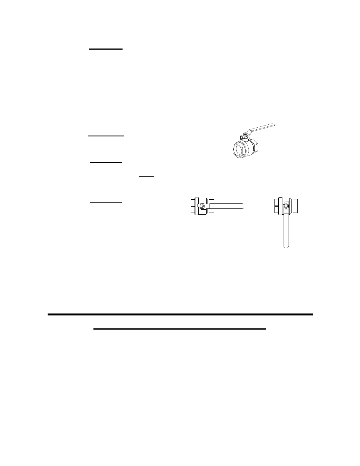
1.2 EMERGENCY SHUTDOWN
If overheating occurs or the gas supply fails to
shut off, close the manual gas shutoff valve
(Figure 1-1) located external to the unit.
The Installer must identify and indicate the
location of the emergency shutdown manual
gas valve to operating personnel.
Water heater Installations within the Commonwealth of Massachusetts must conform to the following
requirements:
• Heater must be installed by a plumber or a gas fitter who is licensed within the Commonwealth of
• Prior to unit operation, the complete gas train and all connections must be leak tested using a
• The vent termination must be located a minimum of 4 feet above grade level.
• If side-wall venting is used, the installation must conform to the following requirements extracted
IMPORTANT
IMPORTANT – FOR MASSACHUSETTS INSTALLATIONS
Massachusetts.
non-corrosive soap.
from 248 CMR 5.08 (2):
Figure 1-1
Manual Gas Shutoff Valve
1-2
Page 7

SAFETY PRECAUTIONS
(a) For all side wall horizontally vented gas fueled equipment installed in every dwelling, building or
structure used in whole or in part for residential purposes, including those owned or operated by the
Commonwealth and where the side wall exhaust vent termination is less than seven (7) feet above
finished grade in the area of the venting, including but not limited to decks and porches, the following
requirements shall be satisfied:
1. INSTALLATION OF CARBON MONOXIDE DETECTORS. At the time of installation of the side wall
horizontal vented gas fueled equipment, the installing plumber or gasfitter shall observe that a hard wired
carbon monoxide detector with an alarm and battery back-up is installed on the floor level where the gas
equipment is to be installed. In addition, the installing plumber or gasfitter shall observe that a battery
operated or hard wired carbon monoxide detector with an alarm is installed on each additional level of the
dwelling, building or structure served by the side wall horizontal vented gas fueled equipment. It shall be
the responsibility of the property owner to secure the services of qualified licensed professionals for the
installation of hard wired carbon monoxide detectors.
a. In the event that the side wall horizontally vented gas fueled equipment is installed in a crawl
space or an attic, the hard wired carbon monoxide detector with alarm and battery back-up may be
installed on the next adjacent floor level.
b. In the event that the requirements of this subdivision can not be met at the time of completion of
installation, the owner shall have a period of thirty (30) days to comply with the above requirements;
provided, however, that during said thirty (30) day period, a battery operated carbon monoxide
detector with an alarm shall be installed.
2. APPROVED CARBON MONOXIDE DETECTORS. Each carbon monoxide detector as required in
accordance with the above provisions shall comply with NFPA 720 and be ANSI/UL 2034 listed and IAS
certified.
3. SIGNAGE. A metal or plastic identification plate shall be permanently mounted to the exterior of the
building at a minimum height of eight (8) feet above grade directly in line with the exhaust vent terminal
for the horizontally vented gas fueled heating appliance or equipment. The sign shall read, in print size no
less than one-half (1/2) inch in size, "GAS VENT DIRECTLY BELOW. KEEP CLEAR OF ALL
OBSTRUCTIONS".
4. INSPECTION. The state or local gas inspector of the side wall horizontally vented gas fueled
equipment shall not approve the installation unless, upon inspection, the inspector observes carbon
monoxide detectors and signage installed in accordance with the provisions of 248 CMR 5.08(2)(a)1
through 4.
(b) EXEMPTIONS: The following equipment is exempt from 248 CMR 5.08(2)(a)1 through 4:
1. The equipment listed in Chapter 10 entitled "Equipment Not Required To Be Vented" in the most
current edition of NFPA 54 as adopted by the Board; and
2. Product Approved side wall horizontally vented gas fueled equipment installed in a room or
structure separate from the dwelling, building or structure used in whole or in part for residential
purposes.
(c) MANUFACTURER REQUIREMENTS - GAS EQUIPMENT VENTING SYSTEM PROVIDED. When
the manufacturer of Product Approved side wall horizontally vented gas equipment provides a venting
system design or venting system components with the equipment, the instructions provided by the
manufacturer for installation of the equipment and the venting system shall include:
1-3
Page 8

SAFETY PRECAUTIONS
1. Detailed instructions for the installation of the venting system design or the venting system
components; and
2. A complete parts list for the venting system design or venting system.
(d) MANUFACTURER REQUIREMENTS - GAS EQUIPMENT VENTING SYSTEM NOT PROVIDED.
When the manufacturer of a Product Approved side wall horizontally vented gas fueled equipment does
not provide the parts for venting the flue gases, but identifies "special venting systems", the following
requirements shall be satisfied by the manufacturer:
1. The referenced "special venting system" instructions shall be included with the appliance or
equipment installation instructions; and
2. The "special venting systems" shall be Product Approved by the Board, and the instructions for
that system shall include a parts list and detailed installation instructions.
(e) A copy of all installation instructions for all Product Approved side wall horizontally vented gas fueled
equipment, all venting instructions, all parts lists for venting instructions, and/or all venting design
instructions shall remain with the appliance or equipment at the completion of the installation.
______________________________________
[End of Extracted Information From 248 CMR 5.08 (2)]
1-4
Page 9
SECTION 2 - INSTALLATION
2.1 RECEIVING THE UNIT
Each KC1000 Heater is shipped as a single
crated unit. The crated shipping weight is
approximately 1500 lb. and must be moved with
the proper rigging equipment for safety and to
avoid damage. The unit should be completely
inspected at the time of receipt from the carrier
before the bill of lading is signed. Each unit has
Tip-N-Tell indicator on the outside of the crate.
This indicates if the unit has been turned on its
side. If the Tip-N-Tell indicator is tripped, do not
sign for the shipment. Note the information on
the carrier’s paperwork and request a freight
claim and inspection by a claims adjuster before
proceeding. Any other visual damage to the
packaging materials should also be fully
explained to the delivering carrier.
2.2 UNPACKING
Carefully unpack the unit. Take care not to
damage the unit jacket when cutting away
packaging materials. A close inspection of the
unit should be made to determine if there has
been any damage incurred during shipment that
was not indicated by the Tip-N-Tell indicator.
INSTALLATION
The freight carrier should be notified
immediately if any damage is detected. The
following standard accessories are included with
each unit and are packed separately within the
unit’s packing container
• Spare Spark Igniter
• Spare Flame Detector
• Differential Regulator Spring:
P/N 122548 (Propane) or
P/N 124803 (Natural Gas)
• Manual 1-1/4" Gas Shutoff Valve
• Drain Valve Assembly
• ASME Pressure/Temperature
Relief Valve
• 2 Lifting Lugs
• Stainless Steel Condensate Cup
• Flue Clamps (2 Pieces)
• Shell Cap
• Wing Nut for Shell Cap
Optional accessories are also separately packed
within the unit’s packing container. Standard and
optional accessories shipped with the unit
should be identified and put in a safe place until
installation/use.
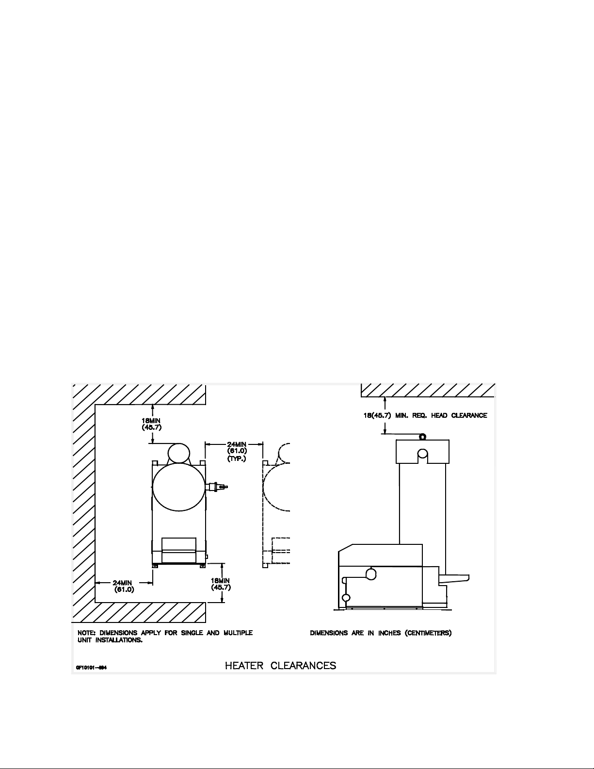
Figure 2.1 Heater Clearance
2-1
Page 10
INSTALLATION
2.3 INSTALLATION
The unit must be installed with the prescribed
clearances for service as shown in Figure 2.1.
These are the minimum
required by AERCO. Local building codes may
require more clearance and take precedence.
WARNING !
KEEP UNIT AREA CLEAR AND FREE
FROM COMBUSTIBLE MATERIALS AND
FLAMMABLE VAPORS AND LIQUIDS.
MASSACHUSSETTS INSTALLATIONS
For water heater installations within the
Commonwealth of Massachusetts, the heater
must be installed by a plumber or a gas fitter
who is licensed within the Commonwealth. In
addition, the installation must comply with all
requirements specified in Section 1 (Safety
Precautions), pages 1-2 to 1-4.
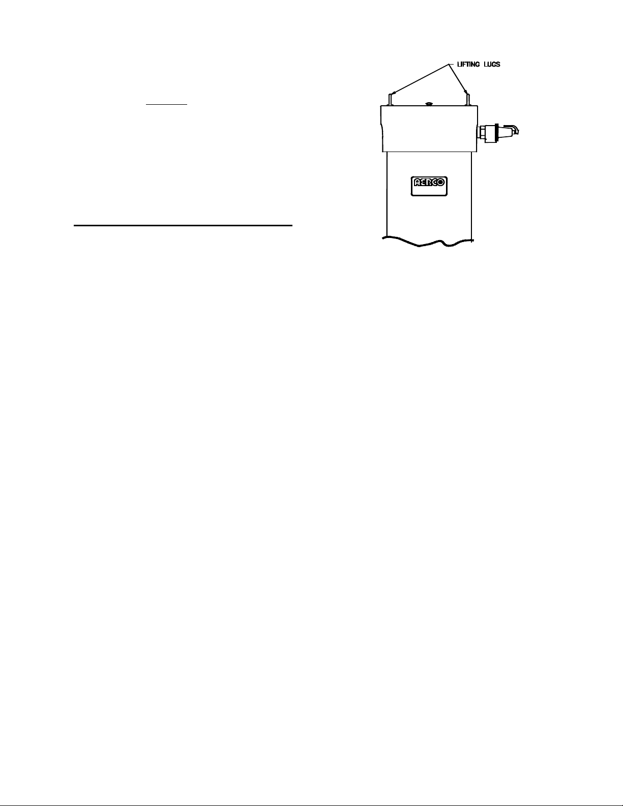
2.3.1 SETTING THE UNIT
Locate the lifting lugs, shipped with the unit, and
attach them to the 5/8” x 11 studs at the top of
the unit. Remove the unit from the wooden skid
and place in position using a block and tackle or
hoist attached to the lifting lugs (Figure 2.2).
USE THE LIFTING LUGS TO MOVE THE
UNIT.
The KC-1000 is U/L approved for installation on
combustible flooring. A 4 to 6 inch high housekeeping concrete pad is recommended and
allows for sufficient drainage of the condensate.
The unit must be secured using only the holes
provided in the frame base. Do not use piping to
secure the unit in place. See drawing AP-A-804
in Appendix E for the base frame dimensions.
In multiple unit installations, it is important to
plan the position of each unit. Sufficient space
for piping connections and maintenance requirements must be given. All piping must include
ample provision for expansion.
clearance dimensions
Figure 2.2
Lifting Lug Location
3
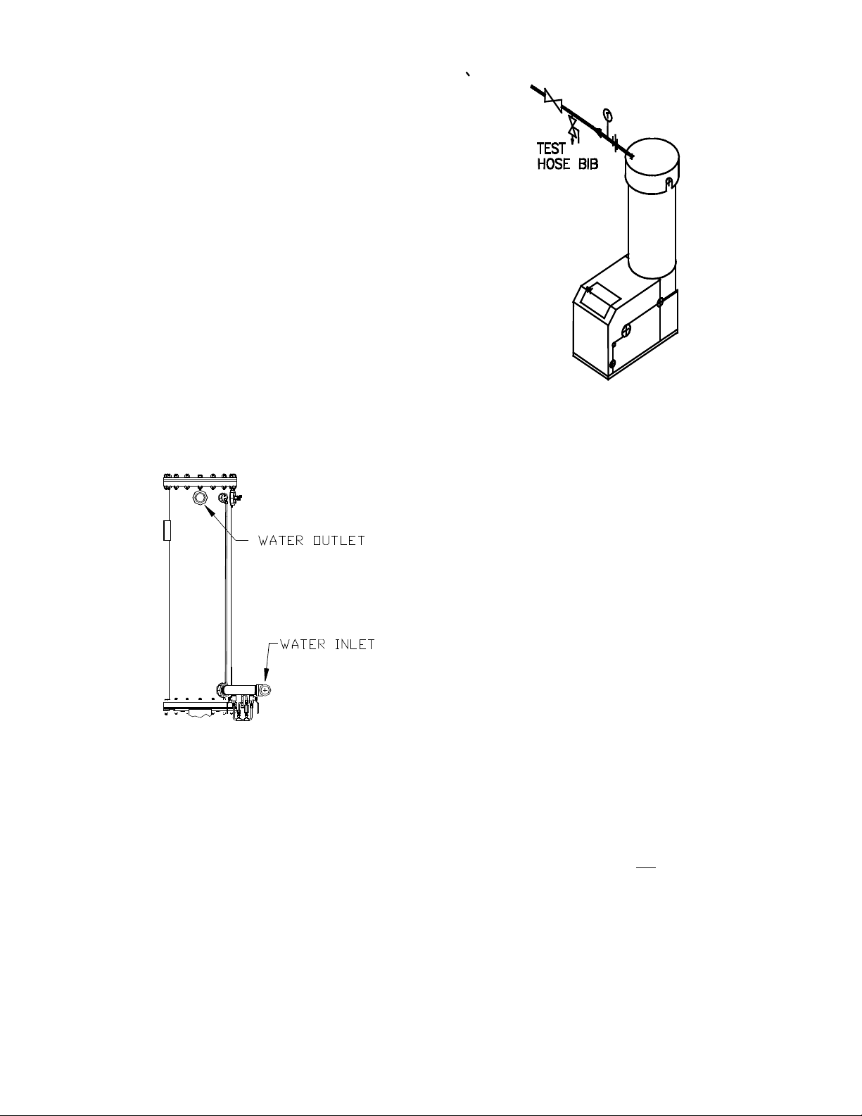
2.3.2 WATER INLET AND OUTLET
PIPING
The locations of the 2" NPT cold water inlet and
hot water outlet piping connections are shown in
Figure 2.3. Flow rates through the unit are
limited to 30 gpm continuous and 40 gpm
intermittent.
The heater is shipped with a 2” NPT x 12” long
stainless steel flex connector. It is important that
this flex connector be installed at the hot water
outlet as mentioned in the installation diagrams
to ensure compliance with the AERCO warranty.
If it is desired to install the flex connector
elbowed towards the rear or top of the unit, two
additional parts (not supplied with heater) are
required. These parts are a 2”NPT x 6” long 304
or 316 stainless nipple and a 2” NPT 304 or 316
stainless elbow. Both of these parts must be
capable of withstanding up to 155 psig @ 210°F.
These parts may be added between the heater
outlet connection and the flex connector.
However, if this heater was ordered with the
optional copper-lined carbon steel shell (contact
your local AERCO Representative to verify), it is
not shipped with, and does not require a flex
connector.
2-2
Page 11
INSTALLATION
Shut-off valves and union conections must be
installed in the inlet and outlet lines for
maintenance. The use of dielectric unions is
recommended. Install the piping and accessories as per the following drawings, located in
Appendix F of this manual.
• SD-A-705 for single units
• SD-A-706 for multiple units
• SD-A-707 for single units with a stratified
tank
• SD-A-708 for multiple units with a stratified
storage tank
• SD-A-709 for single units with a stratified
tank for 2 temperature zones
NOTE:
All piping must be arranged so that it does not
interfere with removal of any cover, inhibit
service or maintenance, or prevent access
between the unit and walls, or another unit.
Figure 2.4
Hose Bib Location
NOTE:
The maximum working pressure for installations
within the Province of Alberta is 87 psig.
Therefore, a pressure & temperature relief valve
with a setting of 75 psig/210°F is supplied with
Alberta shipments. See Drawing AP-A-863 in
Appendix E.
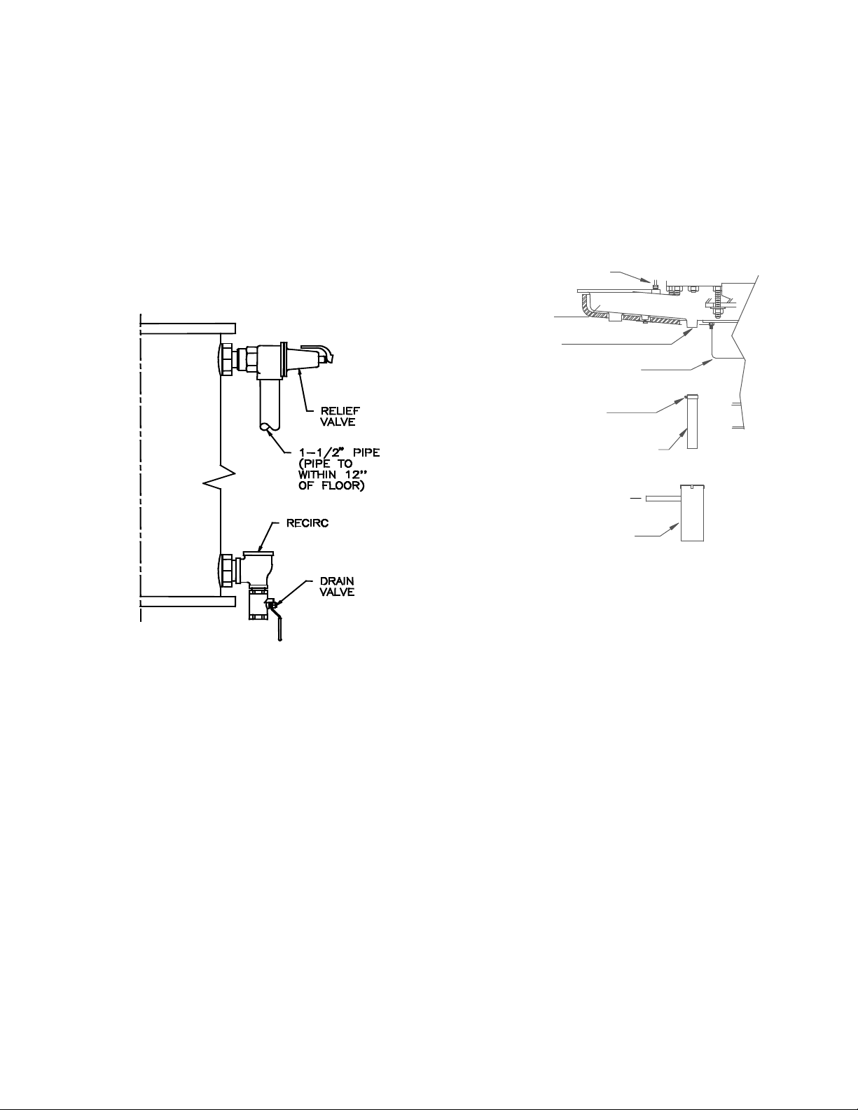
2.3.4 PRESSURE/TEMPERATURE
RELIEF & DRAIN
An ASME rated Pressure/Temperature Relief
Valve is supplied with each unit. With the
exception of Alberta installations (see above
Note), the valve setpoint is 150 psig/210°F.
Install the relief valve as shown in Figure 2.5. A
suitable pipe compound should be used on the
Figure 2.3
Inlet and Outlet Location
2.3.3 TEST HOSE BIB
A Test Hose Bib connection, upstream of the
shut off valve on the hot water outlet, is required
for startup and testing (Figure 2.4). It should be
a minimum of 3/4". The Test Hose Bib cannot
be omitted.
threaded connections. Any excess should be
wiped off to avoid getting any into the valve
body. The relief valve should be pipied to within
12 inches of the floor to prevent injury in the
event of a discharge. The relief piping must be
full size, 1-1/2”, without reduction. No valves,
restrictions, or other blockages are allowed in
the discharge line. In multiple unit installations
the discharge lines must not
together. Each must be individually run to a
suitable discharge location.
VALVE INSTALLATION
be manifolded
2-3
Page 12
INSTALLATION
TEMPERATURE SENSOR
EXHAUST
MANIFOLD
CONDENSATE
DRAIN
BURNER
HOSE CLAMP
1-3/4" O.D. x 8-1 /2 “ LG.
SILICONE HOSE
5/8" O.D. TUBE CONN.
CONDENSATE CUP
PLACED ON FLOOR
A 1” drain valve assembly is furnished with each
unit. The drain valve assembly should be installed as shown in Figure 2.5. and hard piped to
a suitable drain.
2.3.5 SYSTEM RECIRCULATION
The system recirculating line ties into the unit at
the recirculating tee fitting provided in the drain
valve assembly (Figure 2.5). Shut off valves and
union connections are recommended for maintenance. Recirculation flow rates must be kept to
8 gpm or less. In a multiple unit installation, each
unit must be tied into the system recirculation
system.
3. Attach a length of 3/4 inch I.D. polypropylene
tubing to the condensate cup drain tube and
route it to a floor drain. . If a floor drain is not
available, a condensate pump can be used to
remove the condensate to drain. The
condensate drain line must be removable for
routine main-tenance. Therefore, DO NOT
hard-pipe.
4. Replace the rear cover and side panel on the
unit.
Figure 2.5
Pressure/Temperature Relief and Drain
Valve Installation Location
2.3.6 CONDENSATE PIPING
The KC Heater is designed to condense.
Therefore, the installation site must include
suitable provisions for condensate drainage or
collection. A stainless steel condensate cup is
separately packed within unit’s shipping container. To install the condensate cup, proceed as
follows:
1. Remove the left side panel and only the left
half of the rear cover to provide access to the
exhaust manifold and burner (Figure 2.6).
2. Insert the 1-3/4 inch manifold drain hose into
the condensate cup. Allow the cup to rest on
the floor directly beneath the manifold drain
hole (Figure 2.6).
Figure 2.6
Condensate Drain Assembly Location
2.4 GAS SUPPLY PIPING
AERCO Gas Fired Equipment Gas Components
and Supply Design Guide (GF-1030) should be
consulted before any gas piping is designed or
started.
WARNING !
DO NOT USE MATCHES, CANDLES,
FLAMES OR OTHER SOURCES OF
IGNITION TO CHECK FOR GAS LEAKS
.
CAUTION !
Many soaps used for gas pipe leak testing
are corrosive to metals. The piping must be
rinsed thoroughly with clean water after leak
checks have been completed
.
NOTE:
All gas piping must be arranged so that it does
not interfere with the removal of any cover,
inhibit service, maintenance, or prevent access
between the unit and walls, or another unit.
2-4
Page 13
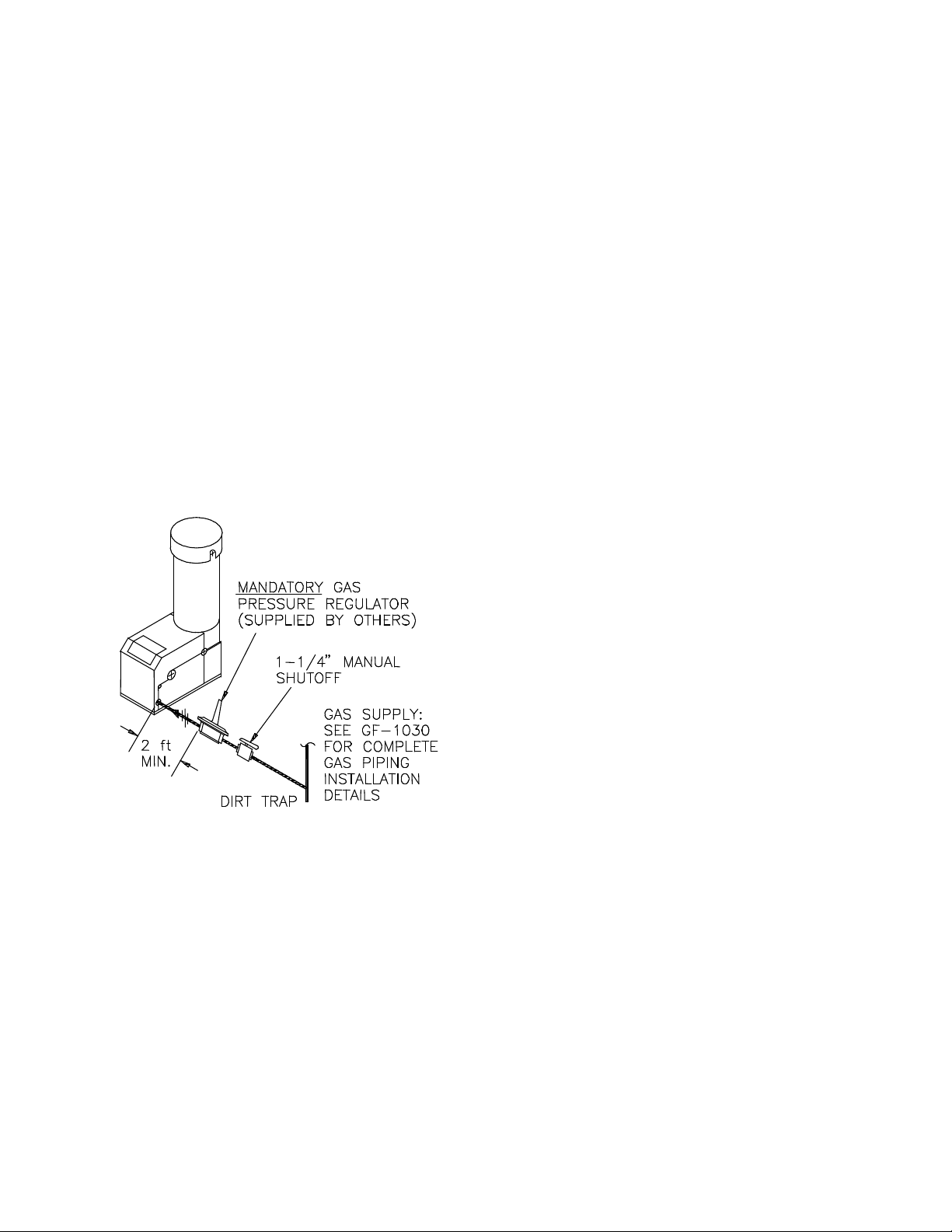
INSTALLATION
The location of the 1-1/4" inlet gas connection
on the right side of the unit is shown in Figure
2.7.
All pipe should be de-burred and internally
cleared of any scale or iron chips before
installation. No flexible connectors or nonapproved gas fittings should be installed. Piping
should be supported from floor or walls only and
must not be secured to the unit.
A suitable piping compound approved for use
with gas should be used sparingly. Any excess
must be wiped off to prevent clogging of
components.
To avoid damage to the unit when pressure
testing gas piping, isolate the unit from the gas
supply piping. At no time should there be more
than 1 psig maximum to the unit. Bubble test all
external piping thoroughly for leaks using a soap
and water solution or suitable equivalent. The
gas piping must meet all applicable codes.
Figure 2.7
Gas Supply Regulator and Manual Shut -
Off Valve Location
2.4.1 GAS SUPPLY PRESSURE
REGULATOR
A mandatory external, in-line, supply gas
regulator (supplied by others) must be installed
upstream of each KC1000 and positioned as
shown in Figure 2.7. Union connections should
be placed in the proper locations to allow
maintenance of the regulator if required. The
regulator must be capable of providing the
required gas pressures for natural gas and
propane units as described in the paragraphs
which follow.
Natural Gas:
The maximum static inlet pressure to the unit
must be no more than 14” W.C. Minimum gas
pressure is 8.8” W.C. for FM gas trains and
9.2” W.C. for IRI gas trains when the unit is
firing at maximum input. Gas pressure should
not exceed 11.5” W.C. at any time when firing.
Proper sizing of the gas supply regulator in
delivering the correct gas flow and outlet
pressure is mandatory. The gas supply
pressure regulator must maintain the gas
pressure at a regulated 8.8” W.C. minimum
for FM gas trains and 9.2” W.C. for IRI gas
trains at maximum BTU input (970,000
BTU/HR) for natural gas installations. The
supply gas regulator must be of sufficient
capacity volume, (1000 cfh), for the unit and
should have no more than 1" droop from
minimum to full fire.
Propane:
The maximum static inlet pressure to the unit
must be no more than 14” W.C. Minimum gas
pressure is 7.7” W.C. for FM gas trains and
8.1” W.C. for IRI gas trains when the unit is
firing at maximum input. Gas pressure should
not exceed 11.5” W.C. at any time when firing.
Proper sizing of the gas supply regulator in
delivering the correct gas flow and outlet
pressure is mandatory. The gas supply
pressure regulator must maintain the gas
pressure at a regulated 7.7” W.C. minimum
for FM gas trains and 8.1” W.C. for IRI gas
trains at maximum BTU input (1,000,000
BTU/HR) for propane installations. The supply
gas regulator must be of sufficient capacity
volume, (400 cfh), for the unit and should have
no more than 1" droop from minimum to full
fire.
The supply gas regulator must be rated to
handle the maximum incoming supply gas
pressure. When the gas supply pressure will not
exceed 14” W.C. a non-lock up or flow through
style regulator may be used. When supply gas
pressure will exceed 14” W.C., a lock up style
regulator must be used. The gas supply
regulator must be propery vented to outdoors.
Consult the local gas utility for exact
requirements concerning venting of supply gas
regulators.
CAUTION!
A lockup style regulator must be used when gas
supply pressure exceeds 14” W.C.
2-5
Page 14
INSTALLATION
POWER BOX
BLOWER
SSOV
ACTUATOR
FRAME
USE COPPER CONDUCTORS ONLY FOR FIELD WIRING
60 HZ
DISCONNECT POWER BEFORE SERVICING
DANGER: HIGH VOLTAGE
20 AMP
120 VAC,
NEUTRAL
GROUND
LINE
POWER BOX
AERCO INTERNATIONAL INC.
INPUT POWER
2.4.2 MANUAL GAS SHUTOFF VALVE
A 1-1/4” manual gas shutoff valve is furnished
with each unit and should be positioned as
shown in Figure 2.7. The valve must be installed
upstream of the gas supply regulator in a readily
accessible location.
2.4.3 IRI GAS TRAIN KIT
The IRI gas train is an optional gas train
required in some areas by code or for insurance
purposes. The IRI gas train comes preassembled and wired from the factory. See
Appendix E, Drawing SD-A-661.
The IRI gas train may be ordered pre-assembled
or as separate components. If either IRI gas
train option is ordered a complete instructional
package, detailing field installation will be
included. To obtain a copy of an IRI instructional
package prior to the equipment shipping, contact
your local representative or AERCO.
2.5 ELECTRICAL SUPPLY
The AERCO Gas Fired Equipment Electrical
Power Wiring Guide, (GF-1060), must be
consulted in addition to the following material
before wiring to the unit is started. AC power
connection to the unit are made at the Power
Box.This box is located on the front right side of
the unit as shown in Figure 2.8.
NOTE:
All electrical conduit and hardware should be
installed so that it does not interfere with the
removal of any cover, inhibit service or
maintenance, or prevent access between the
unit and walls or another unit.
2.5.1 ELECTRICAL REQUIREMENTS
Electrical requirements for each unit are 120
VAC, 1 Phase, 60 Hz, 20 Amps from a
dedicated electrical circuit. No other devices
should be on the same electrical circuit as a
KC1000 unit.
A double-pole switch must be installed on the
electrical supply line in an easily accessible
location to quickly and safely disconnect
electrical service. DO NOT attach the switch to
sheet metal enclosures of the unit.
After placing the boiler in service, the ignition
safety shutoff device must be tested. If an
external electrical power source is used, the
installed boiler must be electrically bonded to
ground in accordance with the requirements of
the authority having jurisdiction. In the absence
of such requirements, the installation shall
conform to National Electrical Code (NEC),
ANSI/NFPA 70 and/or the Canadian Electrical
Code (CEC) Part I, CSA C22.1 Electrical Code.
The electrical wiring diagram is shown in Figure
2.9. Conduit should be run from the knockouts in
the side of the box in such a manner that it does
not interfere with the removal of any sheet metal
covers. A flexible electrical connection may be
utilized to allow the covers to be easily removed.
AC Power Box Location
Figure 2.8
2-6
Figure 2.9
AC Power Wiring Diagram
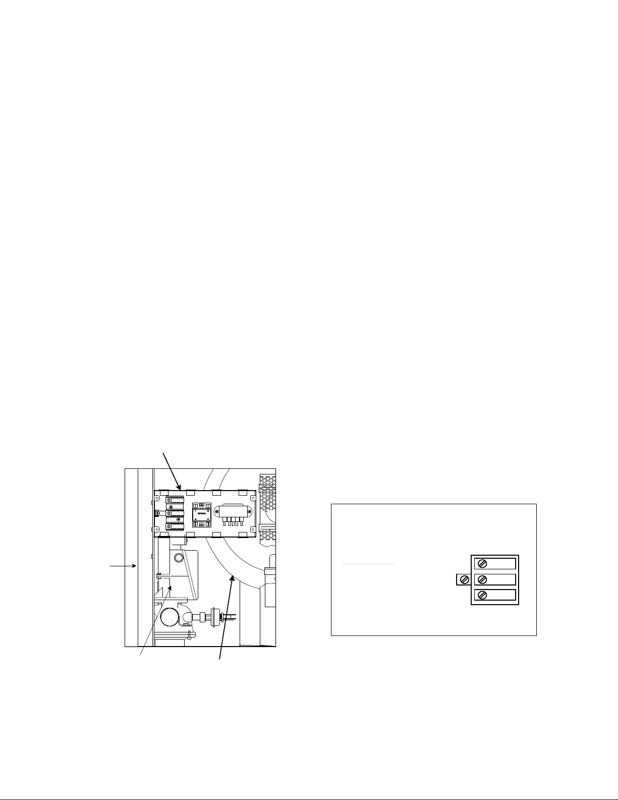
2.6 FIELD CONTROL WIRING
Each unit is fully wired from the factory with an
internal operating control system. No field
control wiring is required for normal operation.
However, the KC1000 control system does allow
for some control and monitoring features.
Page 15
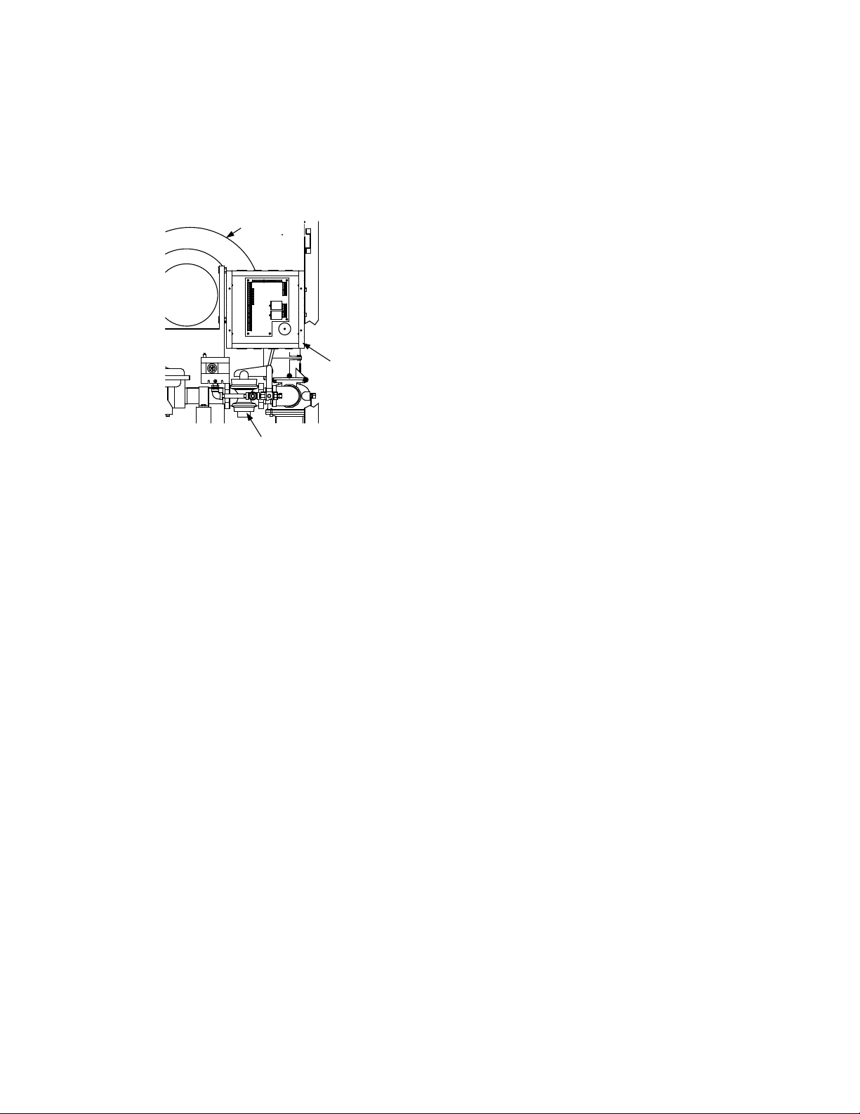
INSTALLATION
GAS SHUT-OFF VALVE
I/O BOX
BLOWER
Wiring for these features can be accomplished
in the I/O Box behind the left side panel (Figures
2.10 and 2.11). The I/O Box is common to both
KC1000 water heaters and boilers. While some
of the inputs and outputs are common to both
water heaters and boilers, some are not
applicable to both. These are noted in the
following paragraphs.
Figure 2.10
Input/Output (I/O) Box Location
CAUTION!
DO NOT make any connections to the I/O
Box terminals labeled “NOT USED”.
Attempting to do so may cause equipment
damage.
2.6.1 OUTDOOR AIR SENSOR IN
Not applicable to Water Heaters.
2.6.2 AUX SENSOR IN
The AUX SENSOR IN terminals can be used to
add an additional temperature sensor for monitoring purposes. This input is always enabled
and is a view only input that can be seen in the
operating menu. The sensor must be wired to
the AUX SENSOR IN and SENSOR COMMON
and must be similar to AERCO BALCO wire
sensor P/N 12449. A resistance chart for this
sensor is located in APPENDIX C.
2.6.3 ANALOG IN
The ANALOG IN + and – terminals are used
when an external signal is used to change the
setpoint (Remote Setpoint Mode) of the heater.
Either a 4 to 20 mA /1 to 5 VDC or a 0 to 20 mA/
0 to 5 VDC signal may be used to vary the setpoint or air/fuel valve position. The factory
default setting is for 4 to 20 mA / 1 to 5 VDC,
however this may be changed to 0 to 20 mA / 0
to 5 VDC using the Configuration Menu
described in Section 3.
If voltage rather than current is selected as the
drive signal, a DIP switch must be set on the
PMC Board located inside the Control Box.
Contact the AERCO factory for information on
setting DIP switches.
All supplied signals must be floating (ungrounded) signals. Connections between the source
and the Heater’s I/O Box must be made using
twisted shielded pair of 18–22 AWG wire such
as Belden 9841(see Figure 2.11). Polarity must
be maintained and the shield must be connected
only at the source end and must be left floating
(not connected) at the Heater’s I/O Box.
Whether using voltage or current for the drive
signal, they are linearly mapped to a 40°F to
240°F setpoint or a 0% to 100% air/fuel valve
position. No scaling for these signals is provided
2.6.4 B.M.S. (PWM) IN
Not applicable to Water Heaters.
2.6.5 SHIELD
The SHIELD terminals are used to terminate any
shields used on sensor wires connected to the
unit. Shields must only be connected to these
terminals.
2.6.6 mA OUT
These terminals provide a 4 to 20 mA output
that can be used to monitor setpoint ( 40°F to
240°F), outlet temperature (30°F to 240°F), or
air/fuel valve position (0% to 100% open). This
function is enabled in the Configuration Menu
(Section 3, Table 3.4).
2.6.7 RS-485 COMM
These terminals are used for RS-485 serial
communication between the unit and an external
“Master” such as an Energy Management
System or other suitable device.
2.6.8 EXHAUST SWITCH IN
These terminals permit an external exhaust
switch to be connected to the exhaust manifold
of the heater. The exhaust sensor should be a
normally open type switch (such as AERCO P/N
123463) that closes (trips) at 500
o
F.
2.6.9 INTERLOCKS
The unit offers two interlock circuits for interfacing with Energy Management Systems and
auxiliary equipment such as pumps or louvers or
other accessories. These interlocks are called
the Remote Interlock and Delayed Interlock
(Figure 2.11). The wiring terminals for these
interlocks are located inside the I/O Box on the
left side of the unit. The I/O Box cover contains a
wiring diagram which shows the terminal strip
2-7
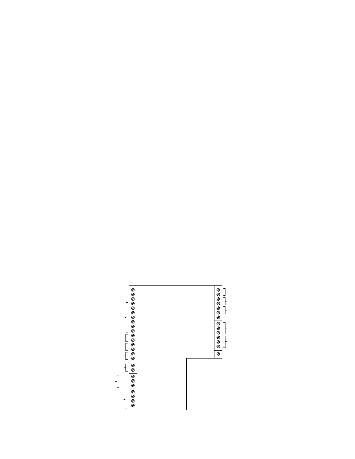
Page 16
INSTALLATION
mA OUT
RS-485
COMM.
+
-
+
-
ANALOG IN
SENSOR COMMON
OUTDOOR SENSOR IN
REMOTE INTL'K IN
B.M.S. (PWM) IN
SHIELD
+
-
+
-
AUX SENSOR IN
NOT USED
EXHAUST SWITCH IN
DELAYED INTL
'K IN
FAULT RELAY
120
VAC, 5A, RES
AUX RELAY
120 VAC, 5A, RES
G
RELAY CONTACTS:
120 VAC, 30 VDC
5 AMPS RESISTIVE
DANGER
120 VAC USED
IN THIS BOX
NOT USED
NOT USED
NC
COM
NO
NC
COM
NO
NOT USED
locations for these interlocks (REMOTE INTL’K
IN and DELAYED INTL’K IN). Both interlocks,
described below, are factory wired in the closed
position.
NOTE:
Both the Delayed Interlock and Remote Interlock
must be in the closed position for the unit to fire.
2.6.9.1 REMOTE INTERLOCK IN
The remote interlock circuit is provided to
remotely start (enable) and stop (disable) the
unit if desired. The circuit is labeled REMOTE
INTL’K IN and is located inside the I/O Box on
the left side of the unit. The circuit is 24 VAC
and comes factory pre-wired closed (jumped).
2.6.9.2 DELAYED INTERLOCK
The delayed interlock is typically used in
conjunction with the auxiliary relay described in
paragraph 2.6.11. This interlock circuit is located
in the purge section of the start string. It can be
connected to the proving device (end switch,
flow switch etc.) of an auxiliary piece of equipment started by the unit’s auxiliary relay. The
delayed interlock must be closed for the heater
to fire. If the delayed interlock is connected to a
proving device that requires time to close
(make), a time delay (Aux Start On Dly) that
holds the start sequence of the unit long enough
for a proving switch to make (close) can be
programmed.
Should the proving switch not prove within the
programmed time frame, the unit will shut down.
The Aux Start On Dly can be programmed from
0 to 120 seconds. This option is locate in the
Configuration Menu (Section 3).
2.6.10 FAULT RELAY
The fault relay is a single pole double throw
(SPDT) relay having a normally open and
normally closed set of relay contacts that are
rated for 5 amps at 120 VAC and 5 amps at 30
VDC. The relay energizes when any fault
condition occurs and remains energized until the
fault is cleared and the CLEAR button is
depressed. The fault relay connections are
shown in Figure 2.11.
2.6.11 AUXILIARY RELAY CONTACTS
Each unit is equipped with a single pole double
throw (SPDT) relay that is energized when there
is a demand for heat and de-energized after the
demand for heat is satisfied. The relay is
provided for the control of auxiliary equipment,
such as pumps and louvers, or can be used as a
unit status indictor (firing or not firing). Its
contacts are rated for 120 VAC @ 5 amps.
Refer to Figure 2.11 to locate the AUX RELAY
terminals for wiring connections.
2-8
Figure 2.11 I/O Box Wiring
Page 17

INSTALLATION
2.7 FLUE GAS VENT INSTALLATION
AERCO Gas Fired Venting and Combustion Air
Guide, GF-1050, must be consulted before any
flue or combustion air venting is designed or
installed. Suitable, U/L approved, positive pressure, watertight vent materials MUST be used
for safety and UL certification. Because the unit
is capable of discharging low temperature
exhaust gases, the flue must be pitched back
towards the unit a minimum of 1/4" per foot to
avoid any condensate pooling and to allow for
proper drainage.
While there is a positive flue pressure during
operation, the combined pressure drop of vent
and combustion air systems must not exceed
140 equivalent feet of 0.81” W.C. Fittings as
well as pipe lengths must be calculated as part
of the equivalent length. For a natural draft
installation the draft must not exceed - 0.25”
W.C. These factors must be planned into the
vent installation. If the maximum allowable
equivalent lengths of piping are exceeded, the
unit will not operate properly or reliably.
For Massachusetts installations, the Heatfab
Division of the Selkirk Corporation provides vent
systems which conform to all applicable
requirements for installations within the
Commonwealth of Massachusetts. Contact
information for this supplier is as follows:
The more common methods of combustion air
supply are outlined in the following paragraphs.
For combustion air supply from ducting, consult
the AERCO GF-1050, Gas Fired Venting and
Combustion Air Guide.
2.8.1 COMBUSTION AIR FROM OUTSIDE
THE BUILDING
Air supplied from outside the building must be
provided through two permanent openings. For
each unit these two openings must have a free
area of not less than one square inch for each
4000 BTUs input of the equipment or 250
square inches of free area. The free area must
take into account restrictions such as louvers
and bird screens. For Canada installations, refer
to the requirements specified in CSA B149.1-10,
8.4.1 and 8.4.3.
2.8.2 COMBUSTION AIR FROM INSIDE
THE BUILDING
When combustion air is provided from within the
building, it must be supplied through two
permanent openings in an interior wall. Each
opening must have a free area of not less than
one square inch per 1000 BTUH of total input or
1000 square inches of free area. The free area
must take into account any restrictions, such as
louvers.
Selkirk Corporation
Heatfab Division
130 Industrial Blvd.
Turners Falls, MA 01376
Phone: 1-800-772-0739
www.heat-fab.com
2.8 COMBUSTION AIR
The AERCO Gas-Fired Heater Venting and
Combustion Air Guide, GF-1050 MUST be
consulted before any flue or inlet air venting is
designed or installed. Air supply is a direct
requirement of ANSI 223.1, NFPA-54, CSA
B149.1 and local codes. These codes should be
consulted before a permanent design is
determined.
The combustion air must be free of chlorine,
halogenated hydrocarbons or other chemicals
that can become hazardous when used in gasfired equipment. Common sources of these
compounds are swimming pools, degreasing
compounds, plastic processing, and refrigerants.
Whenever the environment contains these types
of chemicals, combustion air MUST be supplied
from a clean area outdoors for the protection
and longevity of the equipment and warranty
validation.
NOTE
KC1000 units equipped with Low NOx
Burners require an optional Cold Air
Damper for operation with Direct
Vent/Sealed Combustion. The Cold Air
Damper is also required when the unit is
installed in an area where the combustion
air supply temperature can drop below
55°F. Refer to the following paragraph
(2.8.3) and GF-1050 for installation details
2.8.3 SEALED COMBUSTION
The KC Heater is UL approved for 100% sealed
combustion application when installed properly.
When a sealed combustion air application is
installed, the sealed combustion air piping must
be deducted from the maximum allowable
discharge piping amounts. Each unit must have
a minimum 6" diameter connection made to the
special Inlet Air Adapter # GP-18917 available
from AERCO. This adapter bolts directly on to
the air inlet of the unit’s blower. See installation
instructions with adapter. All inlet air ducts must
be sealed air tight.
2-9
Page 18
INSTALLATION
6" MINIMUM
6x3 REDUCER
COLD AIR DAMPER
(FOR KC1000 LOW NOX)
In addition, Cold Air Damper # 99026 must be
installed. It should be located along the inlet duct
run as close as possible to the KC1000 (See
Figure 2.12). The Cold Air Damper must be
placed on individual sections (one Damper per
unit), not in a manifold section. The adjustment
screw on the Damper should be moved to the
center of the slot position and tightened 1/2 turn
past “finger-tight”. DO NOT over-tighten.
See AERCO Venting Guide GF-1050 for further
details.
Figure 2.12
Sealed Combustion Air Connection
2-10
Page 19
CONTROL PANEL OPERATING PROCEDURES
3
1
2
7
4
6
10
8
9
5
11
12
SECTION 3 - CONTROL PANEL OPERATING PROCEDURES
3.1. INTRODUCTION
The information in this Section provides a guide
to the operation of the KC1000 Water Heater
using the Control Panel mounted on the front of
the unit. It is imperative that the initial startup of
this unit be performed by factory trained
personnel. Operation prior to initial startup by
factory trained personnel will void the equipment
warranty. In addition, the following WARNINGS
and CAUTIONS must be observed at all times.
CAUTION:
All initial installation procedures must be
satisfied before attempting to start the unit
WARNING:
ELECTRICAL VOLTAGES IN THIS SYSTEM
INCLUDE 120 AND 24 VOLTS AC. IT MUST
NOT BE SERVICED OR ACCESSED BY
OTHER THAN FACTORY CERTIFIED
SERVICE TECHNICIANS.
.
WARNING:
DO NOT ATTEMPT TO DRY FIRE THE
HEATER. STARTING THE UNIT WITHOUT
A FULL WATER LEVEL CAN SERIOUSLY
DAMAGE THE UNIT AND MAY RESULT IN
PERSONNEL INJURY OR PROPERTY
DAMAGE. THIS SITUATION WILL VOID
ANY WARRANTY.
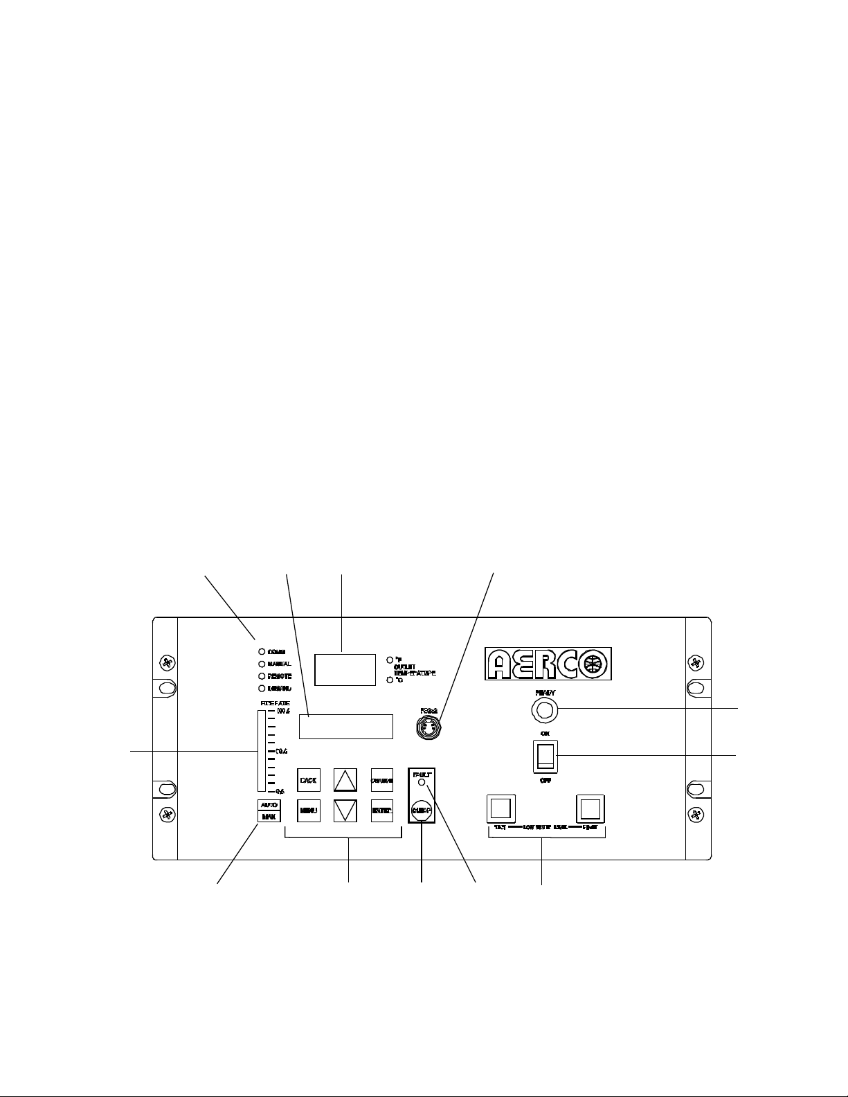
3.2. CONTROL PANEL DESCRIPTION
The KC1000 Control Panel shown in Figure 3-1
contains all controls, indicators and displays
necessary to operate, adjust and troubleshoot
the KC1000 Water Heater. These operating
controls, indicators and displays are listed and
described in Table 3-1. Additional information
on these items are provided in the individual
operating procedures provided in this Section.
Figure 3-1. Control Panel Front View
3-1
Page 20
CONTROL PANEL OPERATING PROCEDURES
FUNCTION
follows:
COMM
Lights when RS-232 communication is occurring
keypad
from an Energy Management System
DEMAND
Lights when there is a demand for heat
Menu Selection
in degrees Fahrenheit or degrees Celsius.
connected to the water heater Control Panel.
5
READY Indicator
Lights when all Pre-Purge conditions have been satisified.
6
ON/OFF Switch
Enables and disables heater operation.
Pressing CLEAR resets the display.
condition occurs. An alarm message will appear in the VFD.
alarms
the Control Panel Menus:
The Menu categories wrap around in the order shown.
category.
Table 3-1. Operating Controls, Indicators and Displays
ITEM
NO.
CONTROL, INDICATOR
OR DISPLAY
1 LED Status Indicators Four Status LEDs indicate the current operating status as
MANUAL
REMOTE
2 VFD Display Vacuum Fluorescent Display (VFD) consists of 2 lines, each
3
OUTLET
TEMPERATURE
Display
4 RS-232 Port Port permits a Laptop Computer or External Modem to be
7
LOW WATER LEVEL
TEST/RESET Switches
Lights when the unit is being controlled using the front panel
Lights when the unit is being controlled by an external signal
capable of displaying up to 16 alphanumeric characters. The
information displayed includes:
Startup Messages
Alarm Messages
Operating Status Messages
3–Digit, 7–Segment LED display continuously displays the
outlet water temperature. The °F or °C LED next to the
display lights to indicate whether the displayed temperature is
Allow the operator to test the operation of the water level
monitor.
Pressing TEST opens the water level probe circuit and
simulates a Low Water Level alarm.
Pressing RESET resets the water level monitor circuit.
8 FAULT Indicator Red FAULT LED indicator lights when a heater alarm
9 CLEAR Key Turns off the FAULT indicator and clears the alarm message
if the alarm is no longer valid. Lockout type alarms will be
latched and cannot be cleared by simply pressing this key.
Troubleshooting may be required to clear these types of
10 MENU Keypad Consists of 6 keys which provide the following functions for
MENU
BACK
Steps through the main menu categories shown in Figure 3-2.
Allows you to go back to the previous menu level without
changing any information. Continuously pressing this key will
bring you back to the default status display in the VFD. Also,
this key allows you to go back to the top of a main menu
3-2
Page 21

CONTROL PANEL OPERATING PROCEDURES
FUNCTION
pressing the ▲ arrow key will increment the selected setting.
setting.
flashing will increment or decrement the displayed setting.
display will stop flashing.
Bargraph
Air/Fuel Valve Position in 5% increments from 0 to 100%
Table 3-1. Operating Controls, Indicators and Displays - Continued
ITEM
NO.
CONTROL, INDICATOR
OR DISPLAY
10
(Cont.)
▲ (Up) Arrow When in one of the main menu categories (Figure 3-2),
pressing this key will select the displayed menu category. If
the CHANGE key was pressed and the menu item is flashing,
▼ (Down) Arrow
When in one of the main menu categories (Figure 3-2),
pressing this key will select the displayed menu category. If
the CHANGE key was pressed and the menu item is flashing,
pressing the ▼ (Down) arrow key will increment the selected
Permits a setting to be changed (edited). When the
CHANGE key is pressed, the displayed menu item will begin
to flash. Pressing the ▲ or ▼ arrow key when the item is
Saves the modified menu information in memory. The
CHANGE
ENTER
11 AUTO/MAN Switch This switch toggles the water heater between the Automatic
and Manual modes of operation. When in the Manual (MAN)
mode, the front panel controls are enabled and the MANUAL
status LED lights.
When in the Automatic (AUTO) mode, the MANUAL status
LED will be off and the front panel controls disabled.
12
VALVE POSITION
20-segment red LED bargraph continuously shows the
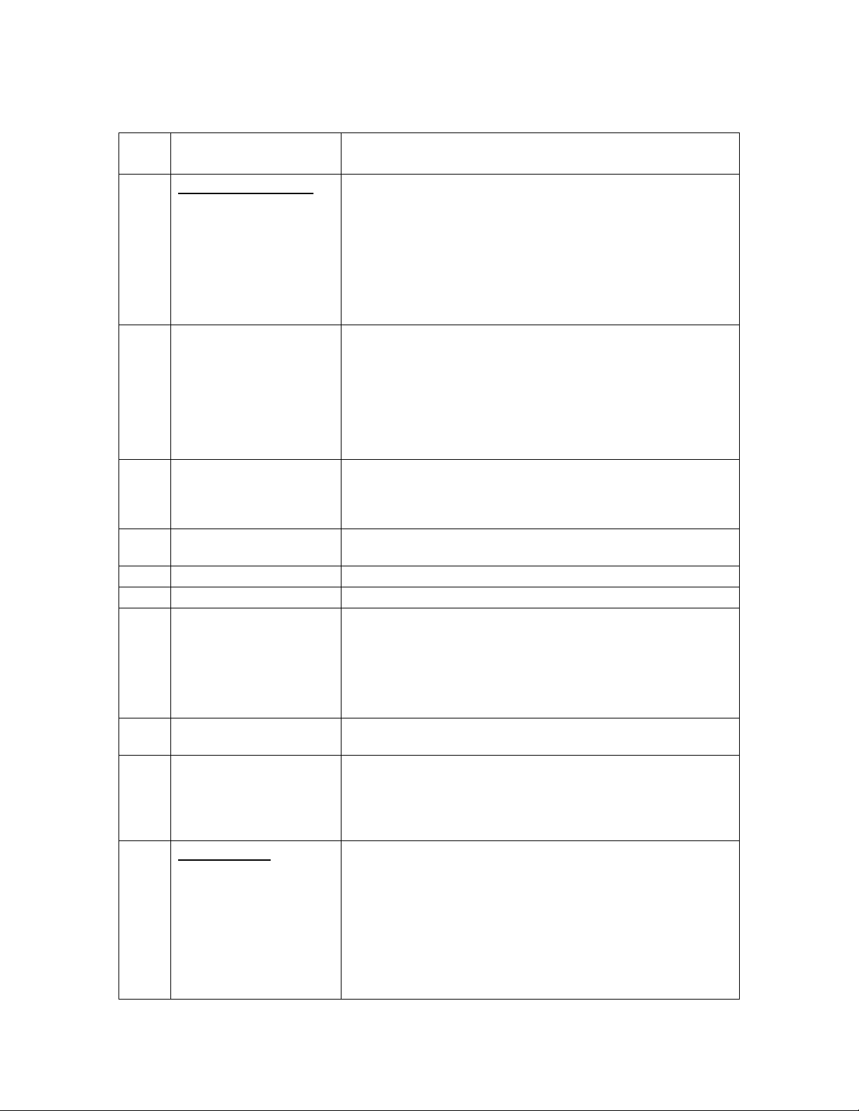
3.3. CONTROL PANEL MENUS
The Control Panel incorporates an extensive
menu structure to permit the operator to set up
and configure the unit. The menu structure
consists of the four major menu categories
shown in Figure 3-2. Each of these menus
contains options to permit operating parameters
to be viewed or changed. The menus are
password-protected to prevent unauthorized
use.
Prior to entering the correct password, the
options contained in the Operating, Setup,
Configuration and Tuning Menu categories can
be viewed. However, with the exception of
Internal Setpoint Temperature (Configuration
Menu), none of the viewable menu options can
be changed.
Once the valid password (159) is entered, the
options listed in the Setup, Configuration and
Tuning menus can be viewed and changed, if
desired.
3.3.1. Menu Processing Procedure
Accessing each menu and option is accomplished using the Menu Keys shown in
Figure 3-1. Therefore, it is imperative that you
be thoroughly familiar with the following basic
steps before attempting to perform specific
menu procedures.
1. The Control Panel will normally be in the
Operating Menu and the VFD will display the
current unit status. Pressing the ▲ or ▼
arrow key will display the other available data
items in the Operating Menu.
2. Press the MENU key. The display will show
the Setup Menu which is the next menu
category shown in Figure 3-2. This menu
contains the Password option which must be
entered if other menu options will be
changed.
3. Continue pressing the MENU key until the
desired menu is displayed.
3-3
Page 22
CONTROL PANEL OPERATING PROCEDURES
OPERATION
SETUP
CONFIGURATION
TUNING
PASSWORD
4. With the desired menu displayed, press the
▲ or ▼ arrow key. The first option in the
selected menu will be displayed.
5. Continue to press the ▲ or ▼ arrow key until
the desired menu option is displayed.
Pressing the ▲arrow key will display the
available menu options in the Top-Down
sequence. Pressing the ▼ arrow key will
display the options in the Bottom-Up
sequence. The menu options will wraparound after the first or last available option
is reached.
6. To change the value or setting of a displayed
menu option, press the CHANGE key. The
displayed option will begin to flash. Continue
to press the ▲ or ▼ arrow key for the option
to be changed. The available menu option
choices will be displayed. The menu option
choices do not wrap around.
7. To select and store a changed menu option,
press the ENTER key.
NOTE:
The following paragraphs provide brief
descriptions of the options contained in each
menu. Refer to Appendix A for detailed
descriptions of each menu option. Refer to
Appendix B for listings and descriptions of
displayed startup, status and error messages.
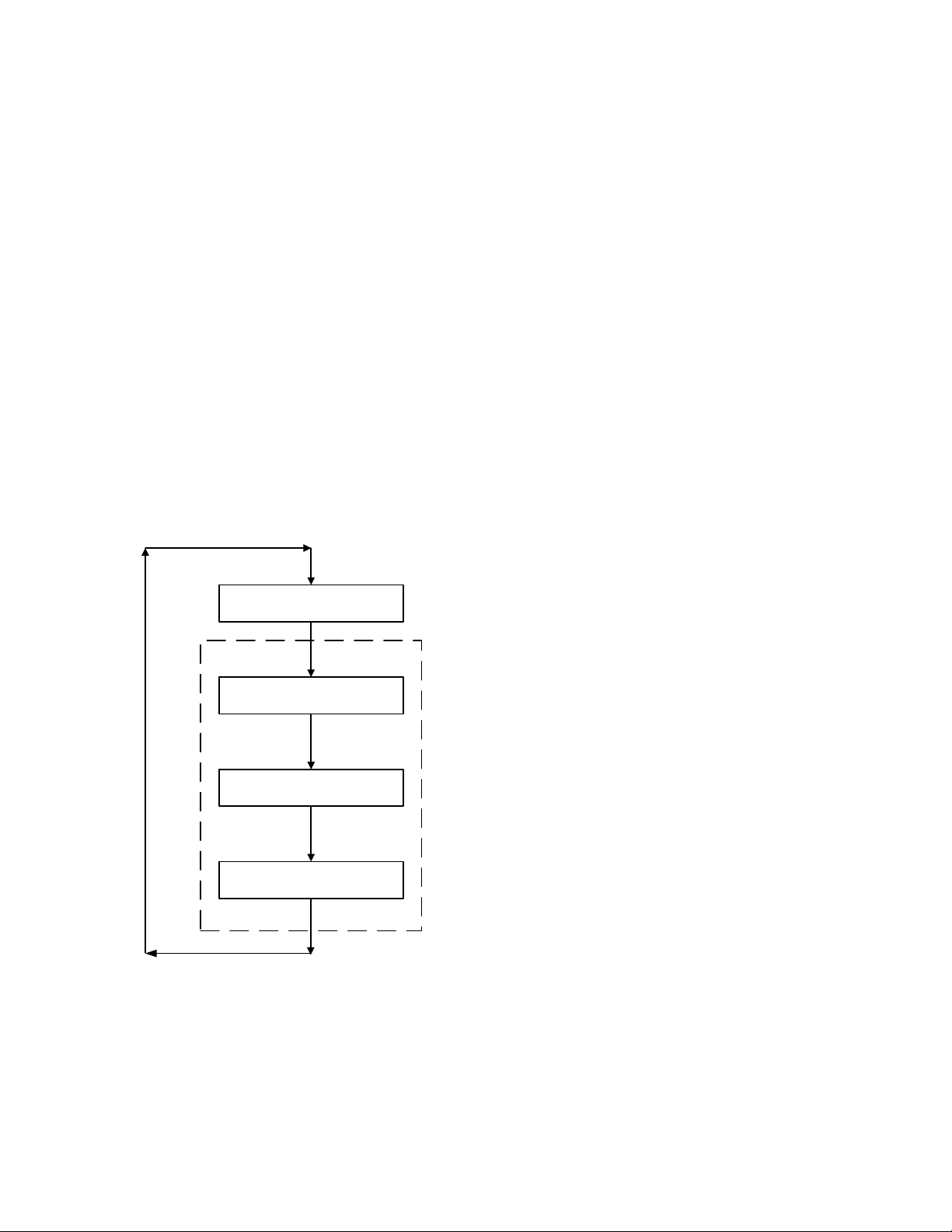
3.4. OPERATING MENU
The Operating Menu displays a number of key
operating parameters for the unit as listed in
Table 3-2. This menu is “Read-Only” and does
not allow personnel to change or adjust any of
the displayed items. Since this menu is “ReadOnly”, it can be viewed at any time without
entering a password. Press the ▲ arrow key to
display the menu items in the order listed (TopDown). Pressing the ▼ arrow key will display
the menu items in reverse order (Bottom-Up).
3.5. SETUP MENU
The Setup Menu (Table 3-3) permits the
operator to set the unit password which is required to change any of the menu options. To
prevent unauthorized use, a previously entered
password will time out after 1 hour. Therefore,
the password must be re-entered when required.
In addition to permitting password entries, the
Setup Menu is also used to enter date and time,
language to be used for display messages, units
of temperature measurements and entries
required for external communication and control
of the unit via the RS-232 port. A view-only
software version display is also provided to
indicate the current Control Box software
version.
Figure 3-2. Menu Structure
3-4
Page 23
CONTROL PANEL OPERATING PROCEDURES
Available Choices or Limits
Menu Item Display
Minimum
Maximum
Default
Status Message
Active Setpoint
40°F
240°F
Aux Temp
30°F
245°F
Outdoor Temp*
-70°F
130°F
Valve Position In
0%
Max Valve
Position
Flame Strength
0%
100%
Run Cycles
0
999,999
Run Hours
0
999,999
Fault Log 0 19
0
Available Choices or Limits
Menu Item Display
Minimum
Maximum
Default
Passsword
0
9999
0
Language
English
English
Time
12:00 am
11:59 pm
Date
01/01/00
12/31/99
Unit of Temp
Fahrenheit
Celsius
Fahrenheit
Comm Address
0
127
0
Baud Rate
2400
9600
Software
Ver 0.00
Ver 9.99
NOTE
The Outdoor Temp display item shown with an asterisk in Table 3-2 will
not be displayed unless the Outdoor Sensor function has been enabled
in the Configuration Menu (Table 3-4).
Table 3-2. Operating Menu
Table 3-3. Setup Menu
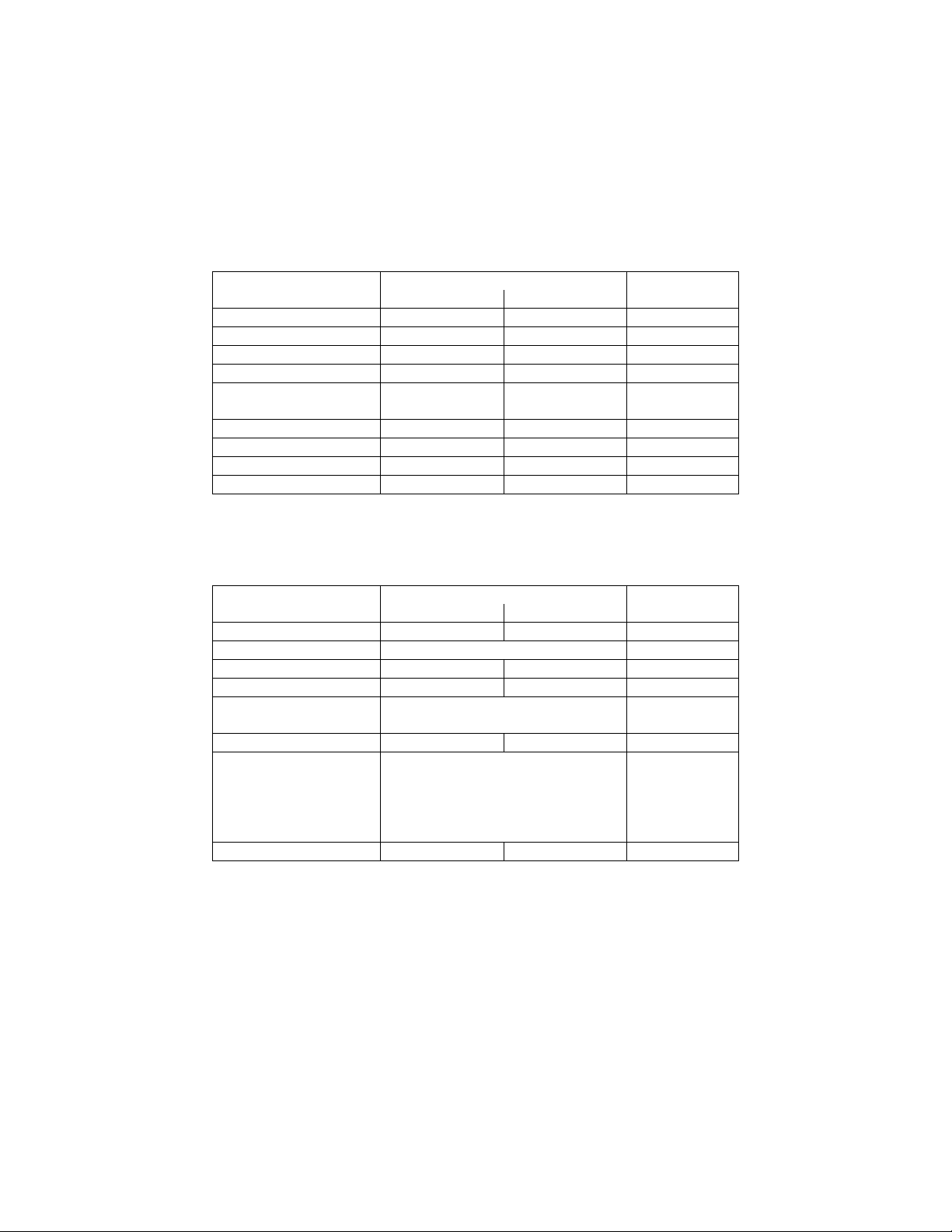
3.6. CONFIGURATION MENU
The Configuration Menu shown in Table 3-4
permits adjustment of the Internal Setpoint
(Setpt) temperature regardless of whether the
valid password has been entered. Setpt is
required for operation in the Constant Setpoint
mode. The remaining options in this menu
require the valid password to be entered, prior to
changing existing entries. This menu contains a
number of other configuration settings which
4800
9600
19.2K
may or may not be displayed, depending on the
current operating mode setting.
NOTE:
The Configuration Menu settings shown in Table
3-4 are factory set in accordance with the
requirements specified for each individual order.
Therefore, under normal operating conditions,
no changes will be required.
3-5
Page 24
CONTROL PANEL OPERATING PROCEDURES
Available Choices or Limits
Menu Item Display
Minimum
Maximum
Default
Table 3-4. Configuration Menu
Internal Setpt Lo Temp Limit Hi Temp Limit 130°F
Unit Type
Unit Size
Fuel Type Natural Gas, Propane Natural Gas
Water Heater Mode
Remote Signal
(If Mode = Remote
Setpoint)
Bldg Ref Temp
(If Mode = Outdoor
Reset)
Reset Ratio
(If Mode = Outdoor
Reset)
Outdoor Sensor Enabled or Disabled Disabled
System Start Tmp
(If Outdoor Sensor =
Enabled)
Setpt Lo Limit 40°F Setpt Hi Limit 60°F
Setpt Hi Limit Setpt Lo Limit 200°F 195°F
Temp Hi Limit 40°F 200°F 195°F
Max Valve Position 40% 100% 100%
Pump Delay Timer 0 min. 30 min. 0 min.
Aux Start On Dly 0 sec. 120 sec. 0 sec.
Failsafe Mode Shutdown or Constant Setpt Shutdown
KC Boiler, KC Boiler LN,
BMK Boiler, BMK Boiler LN,
BMK Boiler Dual, KC Water
Heater, KC Water Heater LN,
Water Heater 2010
0.5 MBTU, 1.0 MBTU
1.5 MBTU, 2.0 MBTU
3.0 MBTU, 3.5 MBTU
4.0 MBTU, 5.0 MBTU
6.0 MBTU
Constant Setpoint,
Remote Setpoint,
4 – 20 mA/1 – 5V
0 -20 mA/0 – 5V
PWM Input (BMS)
Network
40°F 230°F 70°F
0.1 9.9 1.2
30°F 100°F 60°F
KC Water
Heater LN
1.0 MBTU
Constant
Setpoint
4 – 20 mA,
1-5V
3-6
*Analog Output
(See CAUTION at
end of Table 3-4 )
Off, Setpoint, Outlet Temp,
Valve Position 4-20 mA,
Valve Position 0-10V
*Valve
Position
0-10V
Page 25
Table 3-4. Configuration Menu - Continued
Available Choices or Limits
Menu Item Display
Minimum
Maximum
Default
Available Choices or Limits
Menu Item Display
Minimum
Maximum
Default
Min Load Adj
-50°F
50°F
0°F
Max Load Adj
-50°F
50°F
0°F
FFWD Temp
30°F
245°F
Outlet Feedback
On
Off
On
Reset Defaults?
Yes
Are You Sure?
No
Low Fire Timer 2 sec. 600 sec. 2 sec.
Setpt Limiting Enabled or Disabled Disabled
Setpt Limit Band 0°F 10°F 5°F
Network Timeout 5 Sec 999 Sec 30 Sec
HI DB Setpt EN 0% 100% 30%
Demand Offsert 0 25 10
Deadband High 0 25 2
Deadband Low 0 25 2
*CAUTION:
DO NOT CHANGE the Analog Output Menu Item from its Default setting
(Valve Position 0-10V).
CONTROL PANEL OPERATING PROCEDURES
3.7. TUNING MENU
The Tuning Menu items in Table 3-5 are Factory
set for each individual unit.
Table 3-5. Tuning Menu
Do not change these menu entries unless
specifically requested to do so by factory trained
personnel.
No
3-7
Page 26
CONTROL PANEL OPERATING PROCEDURES
STEPPER
MOTOR
DETAIL "A"
DIAL
(DETAIL “A”)
100
BLOWER
BURNER
3.8. START SEQUENCE
When the Control Box ON/OFF switch is set to
the ON position, it checks all pre-purge safety
switches to ensure they are closed. These
switches include:
• Safety Shut-Off Valve Proof of Closure
(POC) switch
• Low Water Level switch
• High Water Temperature switch
• High Gas Pressure switch
• Low Gas Pressure switch
If all of the above switches are closed, the
READY light above the ON/OFF switch will light
and the unit will be in the Standby mode.
When there is a demand for heat (hot water), the
following events will occur:
NOTE:
If any of the Pre-Purge safety device switches
are open, the appropriate fault message will be
displayed. Also, the appropriate fault messages
will be displayed throughout the start sequence,
if the required conditions are not observed.
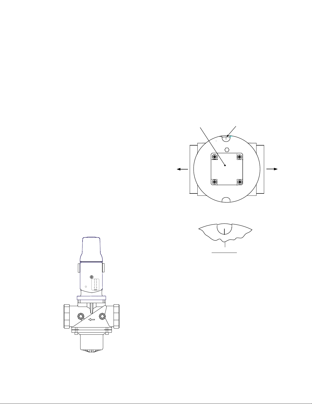
3. With all required safety switches closed, a
purge cycle will be initiated and the following
events will occur:
(a) Blower relay energizes and turns on
blower.
(b) Air/Fuel Valve rotates to the full-open
purge position and closes the purge
position switch. The dial on the Air/Fuel
Valve (Figure 3-4) will read 100 to
indicate that the valve is full-open
(100%).
1. The DEMAND LED status indicator will light.
2. The unit checks to ensure that the proof of
closure switch in the Safety Shut-Off Valve
(SSOV) is closed (Figure 3-3).
Figure 3-3.
Figure 3-4.
Air/Fuel Valve In Purge Position
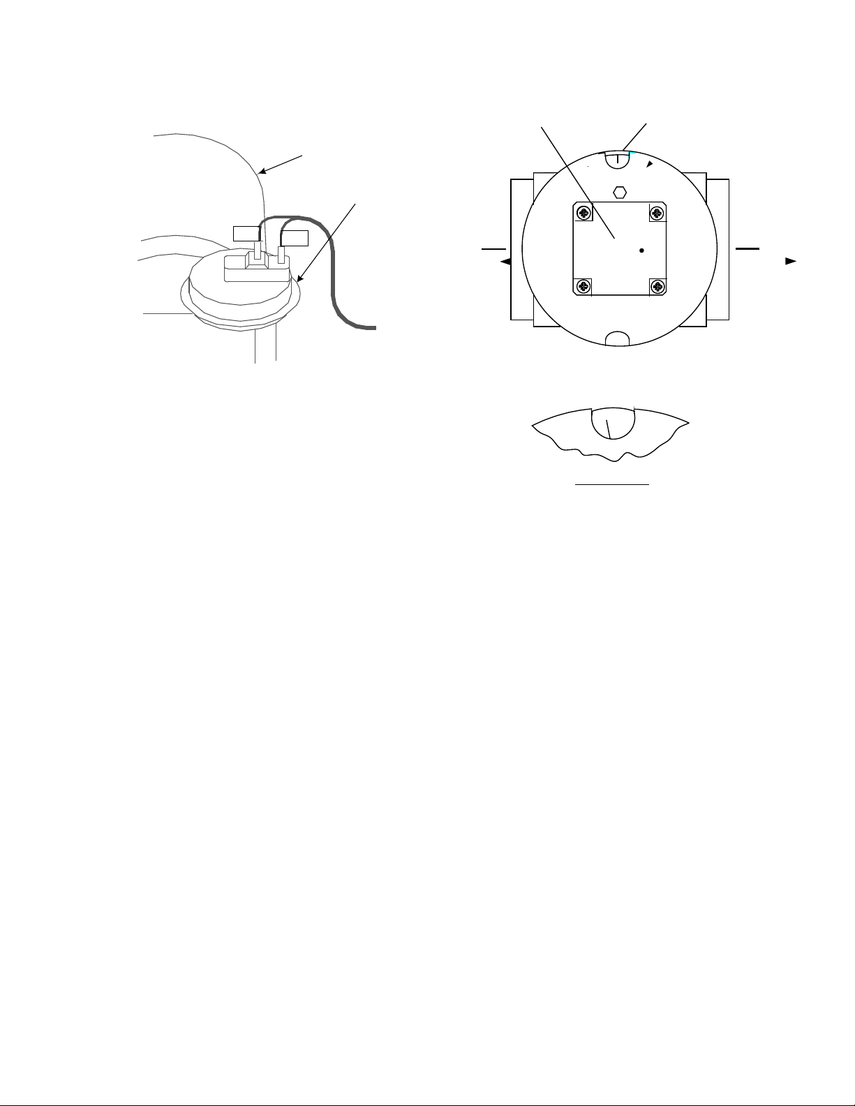
4. The blower proof switch (Figure 3-5) closes;
the display shows Purging and indicates the
elapsed time of the purge cycle in seconds.
3-8
Safety Shut-Off Valve
Page 27
CONTROL PANEL OPERATING PROCEDURES
154
155
AIR/FUEL VALVE
BLOWER PROOF
SWITCH
TO FRAME
HARNESS
STEPPER
MOTOR
DETAIL "A"
DIAL
(DETAIL “A”)
BLOWER
BURNER
2
5
9.
Figure 3-5.
Blower Proof Switch
5. Upon completion of the purge cycle, the
Control Box initiates an ignition cycle and the
following events occur:
(a) The Air/Fuel Valve rotates to the low-fire
ignition position and closes the ignition
switch. The dial on the Air/Fuel Valve
(Figure 3-6) will read between 25 and 35
to indicate that the valve is in the lowfire position.
(b) The igniter relay is activated and pro-
vides ignition spark.
(c) The gas Safety Shut Off Valve (SSOV)
is energized (opened) allowing gas to
flow into the Air/Fuel Valve.
6. Up to 7 seconds will be allowed for ignition to
be detected. The igniter relay will be turned
off one second after flame is detected.
7. After 2 seconds of continuous flame, Flame
Proven will be displayed and the flame
strength will be indicated. After 5 seconds,
the current date and time will be displayed in
place of the flame strength.
8. With the unit firing properly, it will be
controlled by the temperature controller circuitry. The VALVE POSITION will be
continuously displayed on the front panel
bargraph.
Figure 3-6.
Air/Fuel Valve In Ignition Position
10. Once the demand for hot water has been
satisfied, the Control Box will turn off the gas
valve. The blower relay will be deactivated
and the Air/Fuel Valve will be closed.
Standby will be displayed.
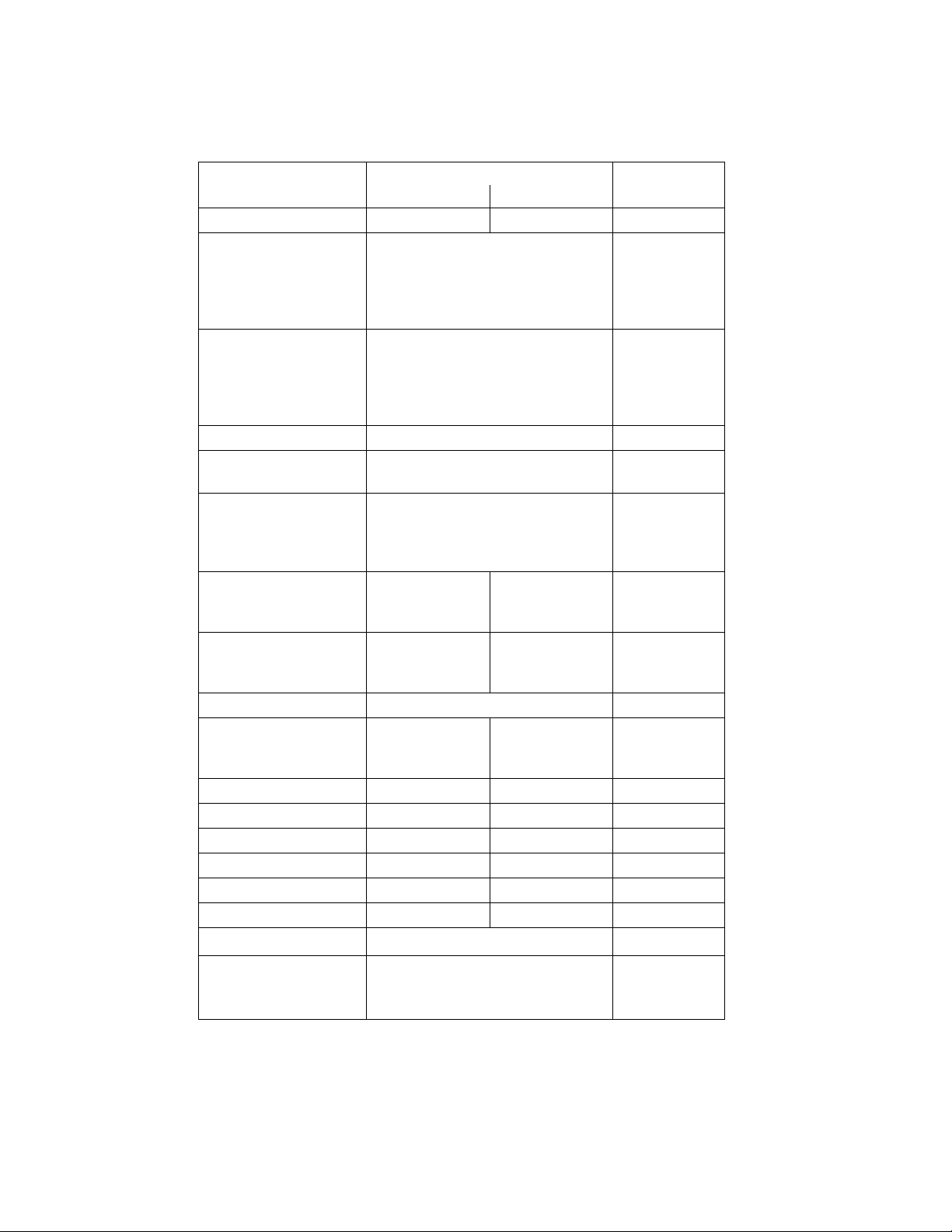
3.9. START/STOP LEVELS
The start and stop levels are the valve position
percentages that start and stop the unit, based
on load. These levels are Factory preset as
follows for natural gas and propane units:
• Start Level: 20% (All units)
• Stop Level: 13% (Natural Gas)
• Stop Level: 16% (Propane)
Normally, these settings should not require
adjustment.
Note that the energy input of the water heater is
not linearly related to the fire rate percentage
(Air/Fuel Valve position). Refer to Table 3-6 for
the relationship between the energy input and
Air/Fuel Valve position (% open) for a unit
running on natural gas.
3-9
Page 28

CONTROL PANEL OPERATING PROCEDURES
Table 3-6.
Relationship Between Air/Fuel Valve Position and Energy Input of a Unit Running on Natural Gas
Air/Fuel Valve
Position
(% Open)
0 0 0
10 0 0
13
(Stop Level)
20 89,000 9%
30 191,000 19%
40 311.000 31%
50 460,000 46%
60 600,000 60%
70 699,000 70%
80 836,000 84%
90 955,000 96%
100 1,000,000 100%
Energy Input
(BTU/Hr)
50,000 5 %
Boiler Energy Input
(% of Full Capacity)
3-10
Page 29

SECTION 4 - INITIAL START- UP
INITIAL START-UP
4.1 INITIAL START- UP REQUIREMENTS
The initial start-up of the KC-1000 Low NOx
Water Heater is comprised of the following
steps:
• Installation completed 100%
• Combustion calibration
• Proper setting of controls and limits
• Temperature calibration
• Safety device testing (see Section 5)
Installation procedures should be completed
100% before performing initial start-up. Also, the
initial start-up must be complete prior to putting
the unit into service. Starting a unit without the
proper piping, venting, or electrical systems can
be dangerous and void the product’s warranty.
These start-up instructions should be precisely
followed in order for the unit to operate safely, at
a high thermal efficiency, and with low flue gas
emissions.
Initial unit start-up must be performed ONLY by
AERCO factory trained start-up and service
personnel. After following the steps in this
section, it will be necessary to perform the safety
device test procedures in Section 5 to complete
the initial unit start-up.
An AERCO Gas Fired Startup Sheet included
with each KC-1000 must be completed for each
unit for warranty validation and a copy must be
returned promptly to AERCO at:
AERCO International, Inc.
159 Paris Ave.
Northvale, NJ 07647
WARNING!
DO NOT ATTEMPT TO FIRE THE UNIT
WITHOUT FULL WATER LEVEL. THIS
CAN SERIOUSLY DAMAGE THE UNIT
AND MAY RESULT IN PERSONAL
INJURY OR PROPERTY DAMAGE. THIS
IS NOT COVERED BY WARRANTY.
CAUTION!
All installation procedures in Section 2 must
be completed before attempting to start the
unit.
4.2 TOOLS AND INSTRUMENTATION
FOR COMBUSTION CALIBRATION
To properly perform combustion calibration on a
KC Heater equipped with a low NOx burner, the
proper instruments and tools must be used and
correctly installed on the unit. The following
paragraphs outline the necessary tools and
instrumentation as well as their installation.
4.2.1 REQUIRED TOOLS AND
INSTRUMENTATION
The following tools and instrumentation are
necessary to perform combustion calibration of a
low NOx unit:
1. Digital Combustion Analyzer - Oxygen
accuracy to ± 0.4%; Carbon Monoxide and
NOx resolution to 1 PPM.
2. A 16" W.C. manometer and plastic tubing.
3. One 1/4” and two 1/8” NPT-to-barbed fittings
for use with manometers.
4. Small and large flat blade screwdrivers.
5. 7/16" open end wrench and small adjustable
wrenches.
6. Tube of silicone adhesive
4.2.2 INSTALLING THE SUPPLY GAS
MANOMETER
1. Close the main manual gas supply valve up
stream of the unit.
2. Remove the 1/4" NPT pipe plug from the
port on the inlet side of the safety shut off
valve (see Figure 4.1).
3. Install a barbed fitting into the pipe plug
tapping.
4. Attach one end of a length of plastic tubing
to the barbed fitting and one end to the 16"
W.C. manometer.
4-1
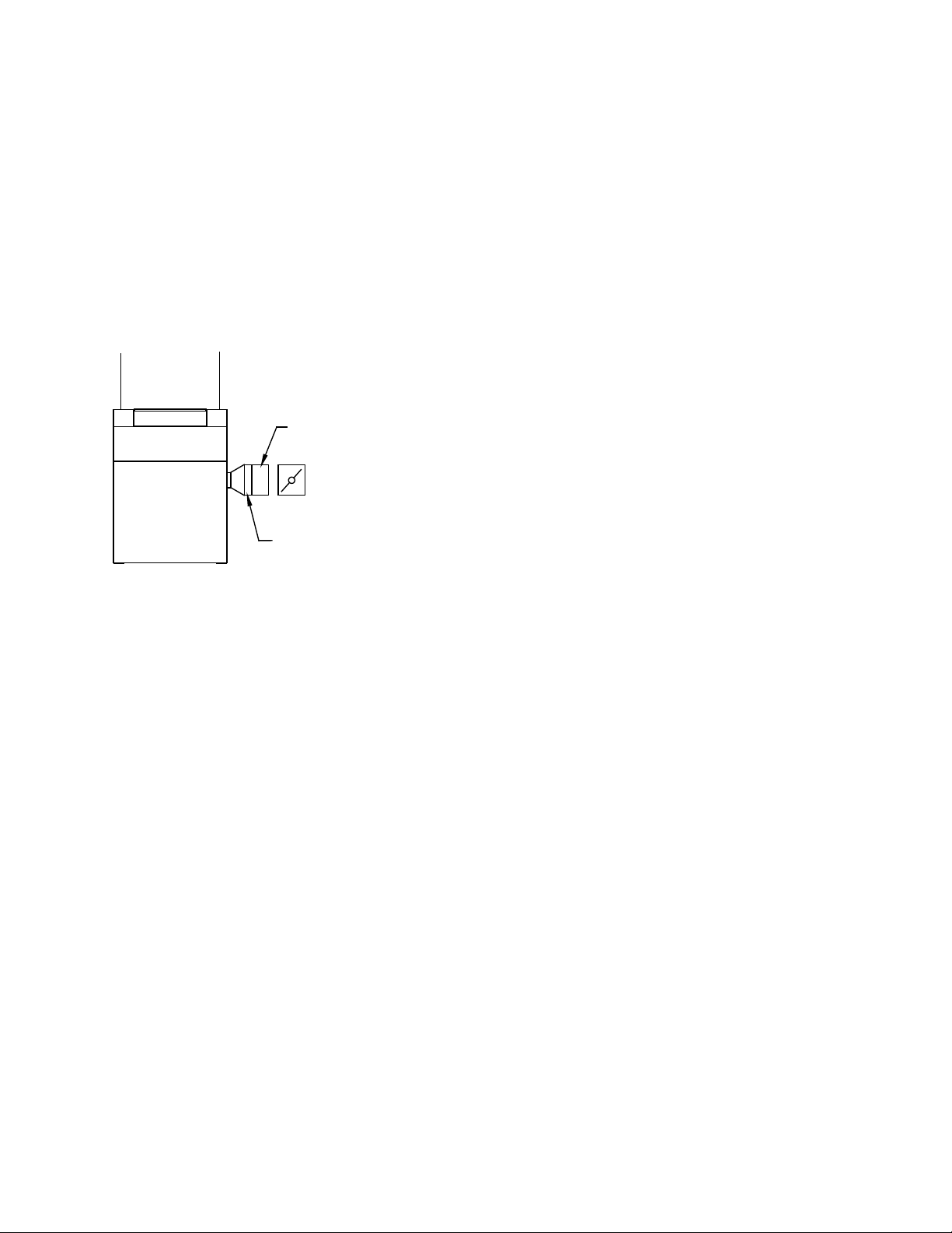
Page 30
SSOV
1/8" NPT PLUG
(INSTALL
MANOMETER
HERE)
3/8" - 1/2"
HOLE FOR
COMBUSTION
ANALYZER
PROBE
EXHAUST
MANIFOLD
12" - 18"
INITIAL START-UP
Figure 4.1
1/8” Gas Plug Location
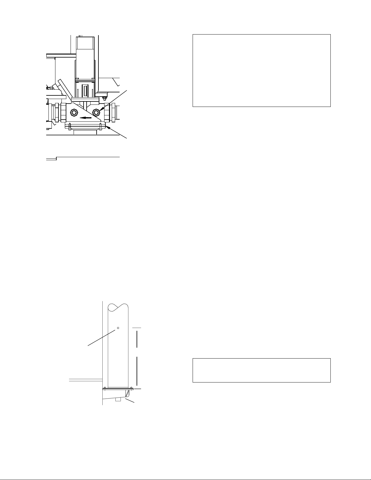
4.2.3 PREPARING THE FLUE VENT
PROBE HOLE
1. If the unit has been installed using the
recommended AL29-4C vent, there will be a
3/8” hole, 18” to 24” above the exhaust
manifold. The outer vent section, that covers
vent connections must be loosened and
moved to uncover the hole (see Figure 4.2).
2. If equipped with one, adjust the stop on the
combustion analyzer probe so that it
extends into the flue gas flow without hitting
the opposite wall of the flue. Do not insert
the probe at this time.
Figure 4.2
Analyzer Probe Hole Location
IMPORTANT
The unit is shipped from the factory set up for
either natural gas or propane, as specified by
the Style No. on the Sales Order. If desired, the
unit can be easily switched from one fuel type to
the other using the regulator spring change
procedure in Appendix I.
For propane units, disregard paragraph 4.3 and
proceed to paragraph 4.4.
4.3 NATURAL GAS COMBUSTION
CALIBRATION
The KC-1000 is shipped combustion calibrated
from the factory. Recalibration as part of a startup is necessary due to differences in altitude,
gas BTU content, gas supply piping and supply
regulators. Factory test data sheets are shipped
with each unit as a reference.
The following combustion calibration procedure
closely follows the factory procedure. By
following this procedure, readjustment of
combustion will be kept to a minimum.
1. Open the supply and return valves to the
unit and ensure that the system pumps are
running.
2. Open the gas supply valve(s) to the unit.
3. If a lockup style regulator is installed as a
gas supply regulator, adjust the gas supply
until a reading of 12” W.C. static pressure is
obtained.
4. Set the ON/OFF switch to the OFF position.
Turn on AC power to the unit. The display
will show LOSS OF POWER and the time
and date.
5. Set the unit to the Manual Mode by pressing
the AUTO/MAN switch. A flashing Manual
Valve Position message will be displayed
with the present position in % open. Also,
the MANUAL LED will light.
NOTE:
For a review of the control panel operating
procedures, refer to Section 3.
6. Adjust the valve position to 0% by pressing
the ▼ arrow key.
7. Set the ON/OFF switch to the ON position.
8. Change the valve position to 25% using the
▲ arrow key. This will put the unit into the
starting sequence.
4-2
Page 31

INITIAL START-UP
Inlet Air
Temp
Oxygen
(±0.2%)
Carbon
Monoxide
*NOx
0°F
7.4%
<100 ppm
<30 ppm
10°F
7.2%
<100 ppm
<30 ppm
25°F
6.9%
<100 ppm
<30 ppm
40°F
6.5%
<100 ppm
<30 ppm
55°F
6.4%
<100 ppm
<30 ppm
70°F
6.2%
<100 ppm
<30 ppm
85°F
5.9%
<100 ppm
<30 ppm
100°F
5.7%
<100 ppm
N/A
DIFFERENTIAL
PRESSURE
REGULATOR
REGULATOR CAP
CAP GASKET
NOTE:
On initial start-up, or return to service from a
fault condition, the unit will remain at a 29%
valve position for two-minutes.
9. Following the warm-up period, increase the
valve position in 20% increments while
monitoring the gas pressure after every
increase. If gas pressure dips below 8.8”
W.C. for FM gas trains and 9.2” for IRI gas
trains at any input valve position percentage,
stop and raise the pressure. Once 100% is
reached, adjust the gas pressure for 8.8”
W.C. (FM) or 9.2” W.C. (IRI).
NOTE:
If 8.8” W.C. for FM gas trains or 9.2” W.C. for IRI
gas trains cannot be obtained at the 100% valve
position, it will be necessary to stop calibration
and contact the local AERCO representative in
your area. Running the unit on insufficient gas
pressure will void the warranty.
10. Once 8.8” W.C. or 9.2” W.C. is set at the
100% level, change the valve position to
30%. Insert the combustion analyzer probe
into the stack.
NOTE:
Always approach a valve position percentage
from the same direction, (i.e., 100% to 30%,
30% to 20%, etc.). Whenever going to an
increased valve position from below (i.e., 20%
to 30%), first go above and then back down to
the desired valve position. This is necessary due
to hysteresis in the air/fuel stepper motor.
Hysteresis causes the air/fuel valve to stop in a
slightly different position if the valve position
percentage is approached from below or above.
This results in a difference in oxygen readings
for the same valve position percentage causing
unnecessary recalibration.
11. Allow enough time for the combustion
analyzer to settle. Compare the measured
oxygen level to the oxygen range for intake
air temperature in Table 1. Also, ensure that
the carbon monoxide (CO) and nitrogen
oxide (NOx) readings do not exceed the
values shown.
12. If the measured oxygen level, CO and NOx
emissions are within the ranges shown in
Table 1, no adjustment is necessary.
Proceed to step 19.
Table 1
Combustion Oxygen Levels for a 30%
Valve Position
-25°F 7.8% <100 ppm <30 ppm
-10°F 7.5% <100 ppm <30 ppm
* NOx readings corrected to 3% oxygen.
13. If the measured oxygen level is not within
the range listed in Table 1, remove the
regulator cap and cap gasket from the
differential pressure regulator (see
Figure 4.3) and proceed to step 14.
Differential Pressure Regulator
14. Use a flat-tip screwdriver to adjust the
differential pressure regulator. Turn the
screwdriver:
• counterclockwise to increase the
oxygen level
• clockwise to decrease the oxygen level
Figure 4.3
4-3
Page 32

INITIAL START-UP
Inlet Air
Temp
Oxygen
(±0.2%)
Carbon
Monoxide
*NOx
0°F
<10%
<100 ppm
<30 ppm
10°F
<10%
<100 ppm
<30 ppm
25°F
<10%
<100 ppm
<30 ppm
40°F
<10%
<100 ppm
<30 ppm
55°F
<10%
<100 ppm
<30 ppm
70°F
<10%
<100 ppm
<30 ppm
85°F
<10%
<100 ppm
<30 ppm
100°F
<10%
<100 ppm
N/A
Inlet Air
Temp
Oxygen
(±0.2%)
Carbon
Monoxide
*NOx
0°F
6.4
<100 ppm
<30 ppm
10°F
6.3
<100 ppm
<30 ppm
25°F
6.2
<100 ppm
<30 ppm
40°F
6.1
<100 ppm
<30 ppm
55°F
5.9
<100 ppm
<30 ppm
70°F
5.8
<100 ppm
<30 ppm
85°F
5.6
<100 ppm
<30 ppm
100°F
4.7
<100 ppm
N/A
Inlet Air
Temp
Oxygen
(±0.2%)
Carbon
Monoxide
*NOx
55°F
7.5%
<100 ppm
<30 ppm
70°F
6.5%
<100 ppm
<30 ppm
85°F
5.5%
<100 ppm
<30 ppm
100°F
4.5%
<100 ppm
N/A
15. Replace the regulator cap and cap gasket
and wait for the analyzer reading to settle.
16. When the analyzer reading settles, compare
the new oxygen reading to Table 1.
17. If necessary, repeat the adjustment until the
oxygen level is within the range specified in
Table 1.
18. Replace the regulator cap and cap gasket.
NOTE:
Adjust only the differential regulator at 30%
control signal; do not adjust the air shutter.
19. Once the oxygen level is within the specified
range at 30%, change the valve position to
16%.
20. Oxygen levels at the 16% valve position
should be as shown in Table 2. Also,
ensure that the CO and NOx readings do
not exceed the values shown. No
adjustment should be necessary. Contact
the Factory if the oxygen, CO or NOx levels
are not within the specified ranges.
Table 2
Combustion Oxygen Levels for a 16%
Valve Position
22. If the optional Cold Air Damper (P/N 99026)
is installed, compare the measured oxygen
level with the levels in Table 3. If the Cold
Air Damper is not installed, compare the
oxygen levels with the readings in Table 3A.
Table 3
Combustion Oxygen Levels for a 100%
Valve Position With
-25°F 6.7 <100 ppm <30 ppm
-10°F 6.5 <100 ppm <30 ppm
* NOx readings corrected to 3% oxygen.
Cold Air Damper
Table 3A
Combustion Oxygen Levels for a 100%
Valve Position Without
Cold Air Damper
-25°F <10% <100 ppm <30 ppm
-10°F <10% <100 ppm <30 ppm
* NOx readings corrected to 3% oxygen.
NOTE:
At a 100% valve position, the KC1000 will not
operate reliably at inlet air temperatures below
55°F if the Cold Air Damper (P/N 99026) is not
installed. See paragraphs 2.8.2 and 2.8.3.
21. Change the valve position to 100% and
allow the combustion analyzer to settle.
* NOx readings corrected to 3% oxygen.
23. If the measured oxygen reading is below the
oxygen range in Table 3 (or 3A), loosen the
two bolts that secure the inlet air shutter to
the unit using a 7/16” wrench (see
Figure 4.4). Open the shutter 1/4” to 1/2” to
increase the oxygen level, then tighten the
nuts.
24. Wait for the analyzer to settle, then compare
the new oxygen reading to Table 3 (or 3A).
Repeat the inlet air shutter adjustment until
the oxygen is within the specified range.
Also, ensure that the CO and NOx
emissions do not exceed the values shown.
Firmly tighten the inlet air shutter locking
nuts when finished.
4-4
Page 33

BLOWER
OUTLET
BLOWER
INLET
SCREEN
SHUTTER
SHUTTER
LOCKING NUTS
Figure 4.4
Air Shutter Locking Nut Location
REMINDER:
At 30% valve position, adjust only the differential
pressure regulator. At 100% valve position,
adjust only the inlet air shutter.
25. If the measured oxygen reading is above the
oxygen range in Table 3 (or 3A), loosen the
two 7/16" locking nuts securing the inlet air
shutter. Close the air shutter 1/4” to 1/2” to
decrease the oxygen level and tighten the
two nuts.
26. Allow the analyzer to settle then compare
the new oxygen reading to Table 3 (or 3A).
27. Repeat the adjustment until the oxygen is
within the specified range. Also, ensure that
the CO and NOx readings do not exceed the
values shown. Firmly tighten the inlet air
shutter locking nuts when finished.
NOTE:
Adjust the inlet air shutter only at 100% valve
position. Do Not adjust the differential pressure
regulator.
28. Change the valve position to 30%. Allow
time for the combustion analyzer to settle.
Check the measured oxygen level, CO and
NOx emissions to ensure that they are still
within the ranges shown in Table 1.
29. Continue these procedures until all oxygen
levels are within the ranges specified in
Tables 1, 2, 3 (or 3A).
INITIAL START-UP
30. Record all readings on the AERCO start-up
sheet provided with each unit. Proceed to
paragraph 4.5 when all natural gas
combustion calibration procedures are
completed.
IMPORTANT
The unit is shipped from the factory set up for
either natural gas or propane, as specified by
the Style No. on the Sales Order. If desired, the
unit can be easily switched from one fuel to the
other using the regulator spring change
procedure in Appendix I.
Since the required gas supply pressures for
propane differ from those required for natural
gas, the Propane Combustion Calibration
procedures are repeated in their entirety in
paragraph 4.4.
4.4 PROPANE COMBUSTION
CALIBRATION
The KC-1000 is shipped combustion calibrated
from the factory. Recalibration as part of a startup is necessary due to differences in altitude,
gas BTU content, gas supply piping and supply
regulators. Factory test data sheets are shipped
with each unit as a reference.
Prior to starting these procedures, ensure that
the KC1000 has been set up as specified in
paragraphs 4.2 through 4.2.4.
The following combustion calibration procedure
closely follows the factory procedure. By
following this procedure, readjustment of
combustion will be kept to a minimum.
1. Open the supply and return valves to the
unit and ensure that the system pumps are
running.
2. Open the gas supply valve(s) to the unit.
3. If a lockup style regulator is installed as a
gas supply regulator, adjust the gas supply
until a reading of 11” W.C. static pressure is
obtained.
4. Set the ON/OFF switch to the OFF position.
Turn on AC power to the unit. The display
will show LOSS OF POWER and the time
and date.
4-5
Page 34

INITIAL START-UP
Inlet Air
Temp
Oxygen
(±0.2%)
Carbon
Monoxide
*NOx
0°F
7.4%
<100 ppm
<30 ppm
10°F
7.2%
<100 ppm
<30 ppm
25°F
6.9%
<100 ppm
<30 ppm
40°F
6.5%
<100 ppm
<30 ppm
55°F
6.4%
<100 ppm
<30 ppm
70°F
6.2%
<100 ppm
<30 ppm
85°F
5.9%
<100 ppm
<30 ppm
100°F
5.7%
<100 ppm
N/A
5. Set the unit to the Manual Mode by pressing
the AUTO/MAN switch. A flashing Manual
Valve Position message will be displayed
with the present position in % open. Also,
the MANUAL LED will light.
NOTE:
For a review of the control panel operating
procedures, refer to Section 3.
6. Adjust the valve position to 0% by pressing
the ▼ arrow key.
7. Set the ON/OFF switch to the ON position.
8. Change the valve position to 25% using the
▲ arrow key. This will put the unit into the
starting sequence.
NOTE:
On initial start-up, or return to service from a
fault condition, the unit will remain at a 29%
valve position for two-minutes.
9. Following the warm-up period, increase the
valve position in 20% increments while
monitoring the gas pressure after every
increase. If gas pressure dips below 7.7”
W.C. for FM gas trains and 8.1” for IRI gas
trains at any input valve position percentage,
stop and raise the pressure. Once 100% is
reached, adjust the gas pressure for 7.7”
(FM) W.C. or 8.1” W.C. (IRI).
NOTE:
If 7.7” W.C. for FM gas trains or 8.1” W.C. for IRI
gas trains cannot be obtained at the 100% valve
position, it will be necessary to stop calibration
and contact the local AERCO representative in
your area. Running the unit on insufficient gas
pressure will void the warranty
10. Once 7.7” W.C. or 8.1” W.C. is set at the
100% level, change the valve position to
30%. Insert the combustion analyzer probe
into the stack.
NOTE:
Always approach a valve position percentage
from the same direction, (i.e., 100% to 30%,
30% to 20%, etc.). Whenever going to an
increased valve position from below (i.e., 20% to
30%), first go above and then back down to the
desired valve position. This is necessary due to
hysteresis in the air/fuel stepper motor.
Hysteresis causes the air/fuel valve to stop in a
slightly different position if the valve position
percentage is approached from below or above.
This results in a difference in oxygen readings
for the same valve position percentage causing
unnecessary recalibration.
11. Allow enough time for the combustion
analyzer to settle. Compare the measured
oxygen level to the oxygen range for intake
air temperature in Table 4. Also, ensure that
the carbon monoxide (CO) and nitrogen
oxide (NOx) readings do not exceed the
values shown.
Table 4
Combustion Oxygen Levels for a 30%
Valve Position
-25°F 7.8% <100 ppm <30 ppm
-10°F 7.5% <100 ppm <30 ppm
* NOx readings corrected to 3% oxygen.
12. If the measured oxygen level, CO and NOx
emissions are within the ranges shown in
Table 4, no adjustment is necessary.
Proceed to step 19.
13. If the measured oxygen level is not within
the range listed in Table 1, remove the
regulator cap and cap gasket from the
differential pressure regulator (see
Figure 4.3) and proceed to step 14.
4-6
Page 35

INITIAL START-UP
Temp
(±0.2%)
Monoxide
*NOx
0°F
<10%
<100 ppm
<30 ppm
10°F
<10%
<100 ppm
<30 ppm
25°F
<10%
<100 ppm
<30 ppm
40°F
<10%
<100 ppm
<30 ppm
55°F
<10%
<100 ppm
<30 ppm
70°F
<10%
<100 ppm
<30 ppm
85°F
<10%
<100 ppm
<30 ppm
100°F
<10%
<100 ppm
N/A
Temp
(±0.2%)
Monoxide
*NOx
0°F
5.6
<100 ppm
<30 ppm
10°F
5.5
<100 ppm
<30 ppm
25°F
5.4
<100 ppm
<30 ppm
40°F
5.3
<100 ppm
<30 ppm
55°F
5.1
<100 ppm
<30 ppm
70°F
5.0
<100 ppm
<30 ppm
85°F
4.8
<100 ppm
<30 ppm
100°F
4.1
<100 ppm
N/A
Inlet Air
Temp
Oxygen
(±0.2%)
Carbon
Monoxide
*NOx
55°F
6.7%
<100 ppm
<30 ppm
70°F
5.7%
<100 ppm
<30 ppm
85°F
4.7%
<100 ppm
<30 ppm
100°F
3.9%
<100 ppm
N/A
14. Use a flat-tip screwdriver to adjust the
differential pressure regulator. Turn the
screwdriver:
• counterclockwise to increase the
oxygen level
• clockwise to decrease the oxygen level
15. Replace the regulator cap and cap gasket
and wait for the analyzer reading to settle.
16. When the analyzer reading settles, compare
the new oxygen reading to Table 4.
17. If necessary, repeat the adjustment until the
oxygen level is within the range specified in
Table 4.
18. Replace the regulator cap and cap gasket.
NOTE:
Adjust only the differential regulator at 30%
control signal; do not adjust the air shutter.
19. Once the oxygen level is within the specified
range at 30%, change the valve position to
16%.
20. Oxygen levels at the 16% valve position
should be as shown in Table 5. Also,
ensure that the CO and NOx readings do
not exceed the values shown. No
adjustment should be necessary. Contact
AERCO if the oxygen, CO or NOx levels are
not within the specified ranges.
Table 5
Combustion Oxygen Levels for a 16%
Inlet Air
Valve Position
Oxygen
Carbon
NOTE:
At a 100% valve position, the KC1000 will not
operate reliably at inlet air temperatures below
55°F if the Cold Air Damper (P/N 99026) is not
installed. See paragraphs 2.8.2 and 2.8.3.
21. Change the valve position to 100% and
allow the combustion analyzer to settle. If
the optional Cold Air Damper (P/N 99026) is
installed, compare the measured oxygen
level with the levels in Table 6. If the Cold
Air Damper is not installed, compare the
oxygen levels with the readings in Table 6A.
Table 6
Combustion Oxygen Levels for a 100%
Valve Position With
Inlet Air
-25°F 5.9 <100 ppm <30 ppm
-10°F 5.7 <100 ppm <30 ppm
* NOx readings corrected to 3% oxygen.
Oxygen
Combustion Oxygen Levels for a 100%
Valve Position Without
Cold Air Damper
Carbon
Table 6A
Cold Air Damper
-25°F <10% <100 ppm <30 ppm
-10°F <10% <100 ppm <30 ppm
* NOx readings corrected to 3% oxygen.
* NOx readings corrected to 3% oxygen.
21. If the measured oxygen reading is below the
oxygen range in Table 6 (or 6A), loosen the
two bolts that secure the inlet air shutter to
the unit using a 7/16” wrench (see
Figure 4.4). Open the shutter 1/4” to 1/2” to
increase the oxygen level, then tighten the
nuts.
4-7
Page 36

INITIAL START-UP
22. Wait for the analyzer to settle and then
compare the new oxygen reading to Table 6
(or 6A). Repeat the inlet air shutter
adjustment until the oxygen is within the
specified range. Also, ensure that the CO
and NOx emissions do not exceed the
values shown. Firmly tighten the inlet air
shutter locking nuts when finished.
REMINDER:
At 30% valve position, adjust only the differential
pressure regulator. At 100% valve position,
adjust only the inlet air shutter.
23. If the measured oxygen reading is above the
oxygen range in Table 6 (or 6A), loosen the
two 7/16" locking nuts securing the inlet air
shutter. Close the air shutter 1/4” to 1/2” to
decrease the oxygen level and tighten the
two nuts.
24. Allow the analyzer to settle then compare
the new oxygen reading to Table 6 (or 6A).
25. Repeat the adjustment until the oxygen is
within the specified range. Also, ensure that
the CO and NOx readings do not exceed the
values shown. Firmly tighten the inlet air
shutter locking nuts when finished.
NOTE:
Adjust the inlet air shutter only at 100% valve
position. Do Not adjust the differential pressure
regulator.
26. Change the valve position to 30%. Allow
time for the combustion analyzer to settle.
Check the measured oxygen level, CO and
NOx emissions to ensure that they are still
within the ranges shown in Table 4.
27. Continue these procedures until all oxygen
levels are within the ranges specified in
Tables 4, 5 and 6 (or 6A).
28. Record all readings on the AERCO start-up
sheet provided with each unit. Proceed to
paragraph 4.5 when all propane combustion
calibration procedures are completed.
4.5 UNIT REASSEMBLY
Once combustion calibration is set properly, the
unit can be re-assembled for permanent
operation.
1. Set the ON/OFF switch to the OFF position.
Disconnect the AC power supply from the
unit.
2. Shut off the gas supply to the unit.
3. Remove the differential pressure regulator
cap and cap gasket (see Figure 4.3).
4. Apply a drop of silicone adhesive to the
regulator adjusting screw to lock its setting.
5. Reinstall the cap and gasket on the
regulator. Tighten the cap using a
screwdriver or wrench.
6. Remove all of the manometers and barbed
fittings and reinstall the pipe plugs using a
suitable thread compound.
7. Remove the combustion analyzer probe
from the vent hole. Seal the probe hole and
replace the vent connection cover.
8. Replace the unit’s panels and hood.
4.6 TEMPERATURE CONTROL
CALIBRATION
Although the unit comes factory set and
calibrated for a 130
necessary to recalibrate temperature control.
There are two primary adjustments for
performing temperature calibration. These are
Min Load Adj and Max Load Adj (minimum and
maximum load adjustment).
Adjustments to these settings are made at
minimum and maximum load conditions and
should be made in small increments from 1 to 3
degrees. After making an adjustment, the outlet
water temperature must be allowed to settle for
several minutes prior to making any further
adjustments.
When calibrating temperature control, observe
the following:
1. The unit must be in the Auto mode of
operation.
2. The Outlet Feedback option in the Tuning
Menu must be off while performing
calibration.
3. Monitor the OUTLET TEMPERATURE
display and VALVE POSITION bar-graph
display to set load conditions and see the
effect of adjustments.
4. Perform the calibration using the Tuning
Menu of the Control Box.
°
F setpoint it is usually
4-8
Page 37

INITIAL START-UP
5. Make small adjustments and allow time
between adjustments for the outlet water
temperature to stabilize.
6. Maintain water flow as constant as possible
during these adjustments.
7. Ensure that recirculation loops are
operational while the calibration is being
performed.
4.6.1 SETTING THE OUTLET WATER
TEMPERATURE SETPOINT
The setpoint temperature of the unit may be
changed by following the procedure below.
However, once a setpoint has been changed,
recalibration may be necessary. The
temperature calibration procedures are provided
in paragraphs 4.6.2 and 4.6.3
To adjust the unit’s setpoint, proceed as follows:
1. Press the MENU key until Configuration
Menu is displayed.
2. Press the ▲ or ▼ arrow key until Internal
Setpt is displayed along with the present
setpoint temperature.
3. To change the setpoint, press the CHANGE
key. The display will begin to flash.
4. Press the ▲ or ▼ arrow key until the
desired setpoint is displayed.
5. Press the ENTER key to save the change.
4.6.2 MINIMUM LOAD ADJUSTMENT
With the unit in operation, check the temperature
control at minimum load as follows:
1. While monitoring the VALVE POSITION
display, create a minimum load on the
system that will yield a steady valve position
between 25% and 35%.
NOTE:
It may be desirable to shut off the outlet valve
and use the hose bib to simulate a minimum flow
load condition.
2. Wait several minutes to allow the outlet
temperature to stabilize under load
conditions.
3. Once stabilized, the OUTLET TEMPER-
ATURE display should read no more than 2
to 3 degrees above the unit’s setpoint.
If the outlet temperature is stabilized,
4.
proceed to the Maximum Load Adjustment
procedure in paragraph 4.6.3. If the unit is
not stabilized, proceed to step 5.
Press the MENU key and select the Tuning
5.
Menu.
6. Press the ▲ or ▼ arrow key until Min Load
Adj is displayed.
7.
Press the CHANGE key. The display will
begin to flash.
8.
Raise or lower the minimum load adjustment
in increments of one or two using the ▲ or
▼ arrow key. Increasing this value will
increase outlet water temperature, while
decreasing it will decrease outlet water
temperature.
Press ENTER to save the change. Allow
9.
time for the system to stabilize between
adjustments
10. Repeat steps 5 through 9 as needed until
the temperature is stabilized at no more than
2 to 3 degrees above the setpoint.
4.6.3 MAXIMUM LOAD ADJUSTMENT
Check the temperature control at maximum load
as follows:
1. While monitoring the VALVE POSITION
display, create a maximum load on the
system that will yield a steady valve position
between 80% and 90%.
NOTE:
It may be necessary to open the outlet valve if it
was closed during minimum load adjustment to
obtain a sufficient flow rate for maximum
adjustment.
2. Wait several minutes to allow the outlet
water temperature to stabilize under load
conditions.
3. Once stabilized, the OUTLET TEMPER-
ATURE display should read no more than 2
to 3 degrees below the unit’s setpoint.
4. If the outlet temperature is stabilized, no
adjustment is necessary. If the unit is not
stabilized, proceed to step 5.
5. Press the MENU key and select the Tuning
Menu.
6. Press the ▲ or ▼ arrow key until Max
Load Adj is displayed.
4-9
Page 38

INITIAL START-UP
OVER-TEMPERATURE
SWITCHES
209
TEMPERATURE SWITCH DETAILS
137
HARNESS
136
FROM SHELL
NCNCCNO
C
25
OVER TEMP. SWITCH
(SEE DETAIL)
7. Press the CHANGE key. The display will
8. Raise or lower the maximum load
9. Press ENTER to save the change. Allow
10. Repeat steps 5 through 9 as needed until
11. If the outlet temperature does not maintain
After performing Temperature Calibration and
prior to placing the water heater in service, be
sure to turn the Outlet Feedback option in the
Tuning Menu back to ON.
4.7 OVER TEMPERATURE LIMIT
SWITCH ADJUSTMENTS
There are two Over-Temperature Limit switches
that turn off the unit when the outlet water
temperature becomes too hot. The lower overtemperature limit switch is adjustable and should
be adjusted 20°F to 40°F above the operating
header temperature. The upper overtemperature limit switch is a manual reset device
and is not adjustable. It will shut the unit off if the
water temperature reaches 240°F. DO NOT
attempt to adjust its setpoint.
To adjust the lower over temperature switch limit
switch, proceed as follows:
1. Remove the wing nut from the top center of
2. The two over-temperature limit switches are
3. Replace the shell cap and wing nut.
begin to flash.
adjustment using the ▲ or ▼ arrow key.
Increasing this value will increase outlet
water temperature, while decreasing it will
decrease water temperature.
time for the system to stabilize between
adjustments
the temperature is stabilized 2 to 3 degrees
below the setpoint.
setpoint after a reasonable amount of time
and adjustment, contact your local AERCO
representative.
NOTE:
the shell cap. Lift the cap off the shell.
located at the top of the shell (Figure 4.5).
DO NOT adjust the upper switch which has
been factory preset. Adjust the lower switch
between 20°F to 40°F higher than the
maximum header temperature the unit may
reach.
Figure 4.5
Over Temperature Limit Switch Location
4-10
Page 39

SECTION 5 - SAFETY DEVICE TESTING PROCEDURES
1/4" NPT PLUG
(INSTALL
MANOMETER
HERE)
SSOV
5.1 TESTING OF SAFETY DEVICES
Periodic testing of all controls and safety devices
is required to insure that they are operating as
designed. Precautions must be taken while tests
are being performed to protect against bodily
injury and property damage.
Systematic and thorough testing of the operating
and safety controls should be performed on a
scheduled basis, or whenever a control component has been serviced or replaced. All testing
must conform to local jurisdictions or codes such
as ASME CSD-1.
NOTE:
MANUAL and AUTO modes are required to
perform the following tests. For a complete
explanation of these modes, see Section 3.
NOTE:
It will be necessary to remove the sheet metal
covers and cap from the unit to perform the
following tests.
WARNING!
ELECTRICAL VOLTAGES IN THIS
SYSTEM INCLUDE 120 AND 24 VOLTS
AC. POWER MUST BE REMOVED PRIOR
TO PERFORMING WIRE REMOVAL OR
OTHER TESTING PROCEDURES THAT
CAN RESULT IN ELECTRICAL SHOCK.
5.2 LOW GAS PRESSURE FAULT TEST
1. Shut off the gas supply to the unit.
2. Install a 0-16” W.C. manometer in the gas
pipe assembly below the low gas pressure
switch. (See Fig. 5.1)
3. Open the gas supply to the unit and depress
the CLEAR button to clear any fault messages..
4. Place the unit in Manual Mode and fire the
unit at a valve position between 25% and
30%.
5. Slowly close the manual gas supply valve
while monitoring the gas pressure. The unit
should fault and shutdown on LOW GAS
PRESSURE when the manometer indicates
approximately 6.5” W.C.
SAFETY DEVICE TESTING
6. Open the gas supply to the unit and press
the CLEAR button on the Control Box.
7. The unit should restart.
Figure 5.1
1/8” Pipe Plug Position for Manometer
Installation
NOTE:
After faulting the unit, the fault message will
be displayed and the fault indicator light will
flash until the CLEAR button is pressed.
5.3 HIGH GAS PRESSURE TEST
1. Start the unit in manual mode at a valve
position between 25% and 30%.
2. Remove either wire # 150 or wire #151 from
the high gas pressure switch. See Fig. 5.2.
3. The unit should shut down on a HIGH GAS
PRESSURE FAULT.
4. Reconnect the wire previously removed from
the high gas pressure switch and depress
the CLEAR button.
5. The unit should restart.
5-1
Page 40

SAFETY DEVICE TESTING
HIGH GAS
PRESSURE
SWITCH
209
13
7
HARNESS
1
3
6
FROM SHELL
NC
NC
CNO
C
120
180
150
DIAL
TEMPERATURE LIMIT SWITCH
SETTING
Figure 5.2
High Gas Pressure Switch
10. After the shell is full, press the LOW
WATER LEVEL RESET button to reset the
low water cutoff. Press the CLEAR button
to reset the FAULT LED and clear the error
message.
11. Set the ON/OFF switch to the ON position.
The unit is now ready for operation.
5.5 WATER TEMPERATURE FAULT
TEST
1. In the normal operating mode, allow the unit
to stabilize at its setpoint.
2. Lower the adjustable temperature limit
switch setting to match the outlet water temperature. (See Fig. 5.3).
5.4 LOW WATER LEVEL FAULT TEST
1. Set the ON/OFF switch in the OFF position.
2. Close the shut-off valves in the supply and
return piping to the unit.
3. Open the drain valve on the unit.
4. Allow air flow into the unit by either opening
the relief valve or by removing the 1/4” plug
in the top of the unit.
5. The LOW WATER LEVEL message will be
displayed and the FAULT LED will flash
after the water level has gone below the
level of the probe.
6. Set the ON/OFF switch to ON. The READY
light should remain off and the unit should
not start. If the unit does start, shut the unit
off immediately and refer fault to qualified
service personnel.
7. Close the drain and pressure relief valve or
reinstall the plug in the top of the unit if
removed.
8. Open the water shut-off valve in the return
piping to the unit to fill the shell.
9. Open the water shut-off valve in the supply
piping to the unit.
Figure 5.3
Temperature Limit Switch Setting
3. Once the switch setting is approximately at
the actual water temperature, the unit should
shutdown. The FAULT LED should be
flashing and the message HIGH WATER
TEMP SWITCH OPEN should be displayed.
The unit should not start.
4. Reset the temperature limit switch setting to
its prior setting.
5. The unit should start once the adjustable
temperature limit switch setting is above the
actual outlet water temperature.
5-2
Page 41

5.6 INTERLOCK TESTS
The unit is equipped with two interlock circuits
called the Remote Interlock and Delayed Interlock. Terminal connections for these circuits are
located in the I/O Box and are labeled REMOTE
INTL’K IN and DELAYED INTL’K IN. These
circuits can shut down the unit in the event that
an interlock is opened. These interlocks are
shipped from the factory jumped (closed).
However, each of these interlocks may be
utilized in the field as a remote stop and start, an
emergency cut-off, or to prove that a device
such as a pump gas booster, or louver is
operational.
5.6.1 REMOTE INTERLOCK
1. Remove the cover from the I/O Box and
locate the REMOTE INTL’K IN terminals.
2. Start the unit in the manual mode at a valve
position between 25% and 30%.
3. If there is a jumper across the REMOTE
INTL’K IN terminals, remove one side of the
jumper. If the interlock is being controlled by
an external device, either open the interlock
via the external device or disconnect one of
the wires leading to the external device.
4. The unit should shut down and display
INTERLOCK OPEN.
5. Once the interlock connection is reconnected, the INTERLOCK OPEN message
should automatically clear and the unit
should resume running.
5.6.2 DELAYED INTERLOCK
1. Remove the cover from the I/O Box and
locate the DELAYED INTL’K IN terminals.
2. Start the unit in manual mode and fire at a
25% to 30% valve position.
3. If there is a jumper across the DELAYED
INTL’K IN terminals, remove one side of the
jumper. If the interlock is connected to a
proving switch of an external device, disconnect one of the wires leading to the proving
switch.
4. The unit should shut down and display
DELAYED INTERLOCK OPEN. The
FAULT LED should be flashing.
SAFETY DEVICE TESTING
5. Once the interlock connection is reconnected, depress the CLEAR button. The
unit should start.
5.7 FLAME FAULT TEST
1. Place the ON/OFF switch in the OFF
position.
2. Place the unit in the Manual Mode and set
the Air/Fuel Valve Position between 25%
and 30%.
3. Close the manual leak detection valve
located between the safety shut-off valve
and the differential regulator (see Fig. 5.4).
4. Start the unit.
5. The unit should shut down after reaching the
Ignition cycle and display FLAME LOSS
DURING IGN.
6. Open the valve previously closed in step 3
and depress the CLEAR button.
7. Restart the unit and allow it to prove flame.
8. Once flame is proven, close the manual leak
detection valve located between the safety
shut-off valve and the differential regulator.
9. The unit should shut down and execute an
IGNITION RETRY cycle by performing the
following steps:
(a) The unit will execute a shutdown purge
cycle for a period of 15 seconds and
display WAIT FAULT PURGE.
(b) The unit will execute a 30 second re-
ignition delay and display WAIT RETRY
PAUSE.
(c) The unit will then execute a standard
ignition sequence and display WAIT
IGNITION RETRY.
10. Since the manual gas shutoff valve is still
closed, the unit will shut down and display
FLAME LOSS DURING IGNITION following
the IGNITION RETRY cycle.
10. Open the valve previously closed in step 8
and depress the CLEAR button. The unit
should restart and fire.
5-3
Page 42

SAFETY DEVICE TESTING
154
155
AIR/FUEL VALVE
BLOWER PROOF
SWITCH
TO FRAME
HARNESS
Figure 5.4
Manual Leak Detection Valve
5.8 AIR FLOW FAULT TEST
1. Start the unit in manual mode and set the
valve position between 25% and 30%.
2. Once the unit has proved flame, remove
either wire #154 or #155 from the blower
proof switch (see Fig. 6.5) located on the
air/fuel valve.
3. The unit should shut down and execute an
IGNITION RETRY cycle by performing the
following steps:
(a) The unit will execute a 30 second re-
ignition delay and display WAIT RETRY
PAUSE.
(b) The unit will then execute a standard
ignition sequence and display WAIT
IGNITION RETRY.
4. The unit should perform an IGNITION
RETRY cycle and then shut down on the
failed ignition attempt. The unit will display
AIRFLOW FAULT DURING PURGE.
5. Replace the wire previously removed from
the blower-proof switch and depress the
CLEAR button. The unit should restart.
ELECTRICAL VOLTAGES IN THIS
WARNING!
SYSTEM INCLUDE 120 AND 24 VOLTS
AC. POWER MUST BE REMOVED PRIOR
TO PERFORMING WIRE REMOVAL OR
OTHER TESTING PROCEDURES THAT
CAN RESULT IN ELECTRICAL SHOCK.
Blower Proof Switch Location and Wiring
5.9 SSOV PROOF OF CLOSURE SWITCH
1. Set the unit’s ON/OFF switch to the OFF
position. Place the unit in manual mode and
set the valve position between 25% and
30%.
2. Remove the Safety Shut-Off Valve (SSOV)
cover to access the terminal connections.
See Fig. 5.6. For units with IRI gas trains,
access the terminal connections of the
downstream SSOV (see drawing SD-A-606
in Appendix E).
3. Remove either wire #149 or #148 from the
SSOV.
4. The unit should fault and display SSOV
SWITCH OPEN.
5. Replace the wire previously removed and
depress the CLEAR button.
6. Start the unit.
7. Remove the wire again when the unit
reaches the purge cycle.
8. The unit should shut down and display
SSOV FAULT DURING PURGE.
9. Replace the wire on the SSOV and depress
the CLEAR button. The unit should restart.
Figure 5.5
5-4
Page 43

SSOV
ACTUATOR
COVER
SSOV
COVER
SCREW
VALVE
COVER
Figure 5.6
SSOV Actuator Cover Screw Location
5.10 PURGE SWITCH OPEN DURING
PURGE
1. Set the unit’s ON/OFF switch to the OFF
position. Place the unit in manual mode and
set the valve position between 25% and
30%.
2. Remove the air/fuel valve cover by rotating
the cover counterclockwise to unlock it and
then pulling it towards you. See Fig. 5.7.
3. Remove one of the two wires from the purge
switch (Fig. 5.8) and start the unit.
4. The unit should begin to start, then shut
down and display PRG SWITCH OPEN
DURING PURGE.
5. Replace the wire on the purge switch and
depress the CLEAR button. The unit should
restart.
SAFETY DEVICE TESTING
Figure 5.7
Air/Fuel Valve Cover Location
5.11 IGNITION SWITCH OPEN DURING
IGNITION
1. Set the unit’s ON/OFF switch to the OFF
position. Place the unit in manual mode and
set the valve position between 25% and
30%.
2. Remove the air/fuel valve cover (Fig. 5.7) by
rotating the cover counterclockwise to
unlock it then pulling it towards you.
3. Remove one of the two wires from the
ignition switch (Fig. 5.8) and start the unit.
4. The unit should begin to start and then shut
down and display IGN SWITCH OPEN
DURING IGNITION.
5. Replace the wire on the ignition switch and
depress the CLEAR button. The unit should
restart.
5-5
Page 44

SAFETY DEVICE TESTING
IGNITION
POSITION
SWITCH
PURGE
POSITION
SWITCH
169
170
172
171
STEPPER
MOTOR
DIAL
BLOWER
BURNER
Figure 5.8
Air/Fuel Valve Purge and Ignition Switch
Locations
5.12 SAFETY PRESSURE RELIEF
VALVE TEST
Test the Safety Pressure Relief Valve in
accordance with ASME Boiler and Pressure
Vessel Code, Section VI.
5-6
Page 45

MAINTENANCE
SECTION 6 – MAINTENANCE
6.1 MAINTENANCE SCHEDULE
The KC1000 Heater requires regular routine maintenance to maintain efficiency and reliability. For best
operation and life of the unit, the following routine maintenance procedures should be performed in the
time periods specified in Table 6-1.
Appendix I contains recommended spare parts lists for maintenance of the KC1000 Heater.
WARNING!
TO AVOID PERSONAL INJURY, BEFORE SERVICING:
(A) DISCONNECT AC POWER TO THE UNIT
(B) SHUT OFF THE GAS SUPPLY TO THE UNIT
(C) ALLOW THE UNIT TO COOL TO A SAFE TEMPERATURE
6.2 SPARK IGNITER
The spark igniter (part no.124570) is located in the body of the burner (see Fig. 6.1). The igniter may be
HOT. Care should be exercised. It is easier to remove the igniter from the unit after the unit has cooled to
room temperature.
To inspect/replace the Igniter (124570):
1. Set the ON/OFF switch on the control panel to the OFF position and disconnect AC power from the
unit.
2. To access to the spark igniter, remove the unit’s left side panel and left rear cover.
3. Disconnect the igniter cable from the igniter contact.
4. Using a 15/16” open-end wrench, remove the igniter from the burner shell.
5. Inspect the igniter for erosion or carbon build-up. If there is substantial erosion of the spark gap or
ground electrode, the igniter should be replaced. If carbon build-up is present, clean the igniter using
fine emery cloth. Repeated carbon build-up on the igniter is an indication that a check of the
combustion settings is required. See Section 4 for Combustion Calibration procedures.
6. Prior to reinstalling the igniter, a very light coating of a conductive anti-seize compound must be
applied to the igniter threads.
7. Reinstall the igniter in the burner shell. Do not over tighten the igniter. A slight snugging up is
sufficient.
8. Reattach the igniter cable.
9. Replace the left side panel and left rear cover. Also, replace the condensate cup to drain tubing if it
was removed.
6-1
Page 46

MAINTENANCE
FLAME
DETECTOR
PROBE
LOWER
BURNER
SHELL
BURNER
HEAD
BURNER
PLATE
IGNITER
(124570)
FLAME DETECTOR
(124837)
STAGED
IGNITION
ORIFICE
Section
Item
6 Mos.
12 Mos.
24 Mos.
Labor Time
(124570)
Flame Detector
(124837)
Combustion
Adjustments.
Testing of Safety
Controls
Pump
Inspect & clean if
necessary
*Manifold &
Tubes
Inspect & clean if
necessary
Inspect and
required)
Figure 6.1
Spark Igniter and Flame Detector Location
Table 6-1. Maintenance Schedule
6.2
6.3
6.4
6.5
6.6
6.7 BTU Transmitter
6.8
6.9 Heat Exchanger
6.10
6.11
Spark Igniter
BTU Transmitter
Condensate
Drain
Low Water Cutoff
Probe (69126)
Inspect Replace 15 mins.
Inspect Replace 15 mins.
Check Check 1 hr.
Test 20 mins.
Oil 15 mins.
50 mins.
**Inspect
Inspect
Clean (as
Inspect &
Clean
Inspect Inspect
Inspect and Clean
(as required)
30 mins.
Replace (Every 24
Mos.)
4 hrs.
1.5 to 3.5 hrs.
20 mins.
*
Recommended only when unit will be run in an extreme condensing mode for prolonged periods of time.
** In areas where water quality is poor or not qualified, inspection and cleaning may be required to assure
trouble-free operation. Hard water deposits must be removed to prevent corrosion and leaking. Checking
at more frequent intervals may be required to prevent scale buildup. See page 6-13 for information about
removing scale deposits using AERCO HydroSkrub scale remover.
6-2
Page 47

MAINTENANCE
6.3 FLAME DETECTOR
The flame detector (part no. 124837) is located in the body of the burner (see Fig. 6.1). The flame
detector may be HOT. Allow the unit to cool sufficiently before removing the flame detector.
To inspect or replace the flame detector:
1. Set the ON/OFF switch on the control panel, to the OFF position and disconnect AC power from the
unit.
2. To access the flame detector, remove the left side panel from the unit.
3. Disconnect the flame detector lead wire.
4. Inspect the detector thoroughly. If eroded, the detector should be replaced. A white coating is an
indication of oxidation, which may be removed with an abrasive cloth (such as Scotch Brite).
NOTE:
Although flame strength may be checked using the C-More controller
display (see OPERATING MENU, paragraph 3.4 and Table 3.2), it is
strongly recommended that you instead use the procedure as described
in paragraph 6.13 for accurate flame strength measurement and to
5. Reinstall the flame detector hand tight only, and reconnect the flame detector lead wire.
6. Replace any panels previously removed.
assure trouble free operation of the flame detection circuit.
6.4 COMBUSTION CALIBRATION
Combustion settings must be checked at the intervals shown in Table 6-1 as part of the maintenance
requirements. Refer to Section 4 for combustion calibration instructions.
6.5 SAFETY DEVICE TESTING
Systematic and thorough tests of the operating and safety devices should be performed to ensure that
they are operating as designed. Certain code requirements, such as ASME CSD-1, require that these
tests be performed on a scheduled basis. Test schedules must conform to local jurisdictions. The results
of the tests should be recorded and preserved as directed by ruling jurisdictions. See Section 5-Safety
Device Testing Procedures.
6.6 BTU TRANSMITTER PUMP LUBRICATION
The BTU Transmitter pump should be lubricated every six months. There are two oil ports located on the
top of the pump, (see Fig. 6.2). Oil using 4 to 5 drops of SAE20 weight non-detergent oil at each port. DO
NOT OVER OIL.
Figure 6.2
BTU Transmitter Pump Oil Port Locations
6-3
Page 48

MAINTENANCE
6.7 BTU TRANSMITTER ASSEMBLY
The BTU Transmitter is a crucial part of the unit’s temperature control system. It must be inspected and
kept free of scale and debris in order for the unit to maintain accurate outlet water temperatures.
To inspect the transmitter:
1. Place the ON/OFF switch in the OFF position.
2. Remove the sheet metal side panels and hood from the unit.
3. Shut the water inlet, outlet and recirculation valves to the unit.
4. Open the drain valve on the unit.
5. Slowly open the pressure relief valve to allow air-flow into the unit.
6. Fully drain the unit.
7. Disconnect electrical power from the unit.
8. Remove the 4 screws holding the BTU transmitter pump to the impeller housing. Remove and set the
pump aside, (See Fig. 6.3).
NOTE:
It is not necessary to disconnect the electrical wires to the pump.
Figure 6.3
BTU Transmitter Pump Disassembly
9. Using a 5/8” and 9/16” wrench, loosen the 4 compression fittings holding the lower tubing assembly in
place, (See Fig. 6.4).
6-4
Page 49

COMPRESSION
FITTINGS
LOWER TUBING ASSEMBLY
Figure 6.4
HYDRAULIC ZERO &
CONTROL ORIFICE
TUBING ASSEMBLY
COLD WATER
MIXING ORIFICE
HOT WATER
MIXING ORIFICE
HYDRAULIC ZERO
NEEDLE VALVE
LOWER TUBING ASSEMBLY
Compression Fitting Locations
MAINTENANCE
10. Carefully remove the lower tubing assembly taking care not to lose either the cold water or hot water
mixing orifice, (See Fig. 6.5).
11. Loosen the compression fitting holding the hydraulic zero and control orifice tube assembly to the
pump’s impeller housing, (See Fig. 6.6).
NOTE:
The cold water mixing orifice (P/N GP-122401) is slightly larger than the
hot water mixing orifice (P/N GP-122760). Each orifice must be correctly
installed for proper temperature control.
Figure 6.5
BTU Transmitter Disassembly
6-5
Page 50

MAINTENANCE
COMPRESSION
FITTINGS
IMPELLER
HOUSING
PUMP OUTLET
TUBE
HOT WATER TUBE
COMPRESSION FITTING
BALL VALVE
Figure 6.6
BTU Transmitter Pump Compression Fitting Locations
12. Remove the compression fitting at the top of the impeller housing and remove the impeller housing,
(See Fig. 6.6).
Figure 6.7
BTU Transmitter Hot Water Tube Disassembly
13. Remove the compression fitting securing the pump outlet tube to the ball valve and remove the pump
outlet tube.
14. Remove the ball valve connected to the hot water tube coming from the top of the shell by loosening
the compression fitting securing it to the hot water tube, (See Fig. 6.7).
15. Loosen the 90
Slide the hot water tube down slightly but do not remove it from the unit. Remove the 90
16. Inspect all fittings and tubing for blockage due to scale or debris. Clean or replace as necessary.
17. Inspect the mixing orifice for blockage or degradation due to erosion, (See Fig. 6.5). Clean or replace
as necessary.
o
compression fitting at the top of the shell holding the hot water tube, (See Fig. 6.8).
o
fitting.
18. The pump impeller may be checked by removing the 4 screws from the cover encasing the impeller in
the housing, (See Fig. 6.9).
6-6
Page 51

MAINTENANCE
IMPELLER HOUSING
COVER
COMPRESSION
FITTING
HOT WATER
TUBE
Figure 6.8
BTU Transmitter Shell Components
19. Once the BTU transmitter has been inspected and cleaned, reassemble in the reverse order.
6.8 MANIFOLD AND EXHAUST TUBES
The presence of even trace amounts of chlorides and/or sulfur, in the combustion air and fuel sources,
can lead to the formation of deposits on the inside of the exchanger tubes, the exhaust manifold, and/or
the condensate cup. The degree of deposition is influenced by the extent of the condensing operation and
the chloride and sulfur levels that vary significantly from application to application.
Figure 6.9
Impeller Housing Disassembly
NOTE:
Do not attempt to adjust the Hydraulic Zero Needle Valve. This is a
factory-preset item. Refer to Figure 6.5. If setting has been tampered
with or BTU transmitter is being replaced, see procedure in Section
6.12, page 6-17.
NOTE:
Compression fittings are nickel-plated and should be replaced only with
nickel-plated fittings. Do not use brass fittings.
6-7
Page 52

MAINTENANCE
GP-122537
Exhaust Manifold to
Gasket
Gasket
124749
Lower Burner Gasket
124834
Upper Burner Gasket
*124839
Combustion Chamber Liner
GROUND
TERMINAL
UPPER
SCREW
LOWER
BURNER
SHELL
FLAME
DETECTOR
IGNITER
GND WIRE FROM
TRANSFORMER
The following parts will be necessary for reassembly after inspection:
Combustion Chamber
GP-18900 Manifold to Tubesheet
*Not necessary to change but should be on hand in the event damage occurs during the inspection.
To remove the manifold for inspection:
1. Disconnect AC power and turn off the gas supply to the unit.
2. Remove the sheet metal covers from the unit.
3. Disconnect the plastic tubing from the condensate cup to drain and remove the rear covers.
4. Remove the condensate cup from under the unit and the condensate drainage tubing from the
manifold.
5. Disconnect the flame detector and ignition cable wires from the flame detector and igniter contactor.
Remove the flame detector and igniter as per paragraphs 6.2, and 6.3.
6. Remove the grounding terminal from the burner by loosening the upper screw and sliding the
connector from the grounding rod, (See Figure 6.10).
7. Loosen the 1/4” NPT union on the low NOx staged ignition assembly (Figure 6.11).
8. Disconnect the staged ignition assembly 1/8” elbow from the 3” long NPT nipple at the bottom of the
burner shell.
9. Remove the 3” long NPT nipple and 1/4” O.D. tube (Figure 6.11) from the burner shell.
6-8
Figure 6.10
Grounding Terminal Location
Page 53

MAINTENANCE
LOW NOx
BURNER
SHELL
STAGED IGNITION
ASSEMBLY
1/8" STREET
ELBOW
1/8" NPT
NIPPLE
3" LONG
1 /4-20
HEX NUTS
(4)
GAS INLET
PIPE
HOSE
CLAMP
AIR/FUEL
VALVE
5/16-18
HEX NUTS (6)
3/8-16 HEX
NUTS &
BOLTS (2)
1/4" NPT UNION
1/4" O.D.
TUBE
EXHAUST
TEMP.
SENSOR
10. Using a 7/16” socket or open end wrench, remove the four 1/4-20 nuts on the gas inlet pipe flange at
the burner.
Figure 6.11
Burner Disassembly Diagram
11. Using two 9/16” wrenches, remove the two 3/8-16 hex nuts and bolts on the gas inlet pipe flange at
the air/fuel valve (Figure 7.3). Remove the gas inlet pipe.
12. Loosen the hose clamp on the air/fuel valve outlet (Figure 6-11)
13. Using a 1/2” socket wrench, remove the six 5/16-18 hex nuts supporting the burner (Figure 6.11).
14. Lower the burner while sliding the air hose off the air/fuel valve. Remove the burner through the rear
of the unit. Due to space limitations, it will be necessary to separate the burner head and shell during
the removal process.
15. Disconnect the exhaust temperature sensor by unscrewing it from the exhaust manifold (Figure 6.12).
Figure 6.12
Exhaust Sensor Connector Location
16. Disconnect the air/fuel valve 12-pin con-nector from the KC wiring harness.
17. Disconnect wires #24 and #17 from the blower proof switch (Figure 6.13).
6-9
Page 54

MAINTENANCE
TO FRAME
HARNESS
BLOWER PROOF
SWITCH
AIR/FUEL VALVE
HOSE CLAMP
Figure 6.13
Blower Proof Switch Wire Location
(older style switch shown at left, newer style at right)
18. Loosen the hose clamp on the air/fuel valve inlet and slide the clamp back towards the blower (Figure
6.14).
Figure 6.14
Air/Fuel Valve Inlet Hose Clamp
19. Using an 11/16” wrench, loosen the compression fittings on the feedback tube between the air/fuel
valve and the differential pressure regulator. Remove the feedback tube (Figure 6.15).
20. Using two 9/16” wrenches, remove the two 3/8-16 hex nuts and bolts securing the air/fuel valve to the
differential pressure regulator (Figure 7.7).
21. Remove the air/fuel valve, taking care not to damage the flange “O”- ring.
6-10
Page 55

MAINTENANCE
AIR/FUEL
VALVE
COMPRESSION
FITTINGS
DIFFERENTIAL PRESS.
REGULATOR
3/8 - 16
HEX NUT/BOLT
SIDE NUT
(1 EACH SIDE)
FRONT NUT
(DO NOT REMOVE)
EXHAUST
MANIFOLD
INSULATION
7/16" HEX HEAD
& FENDER WASHER
(3 PLACES)
Figure 6.15
Feedback Tube and Air/Fuel Valve to Differential Regulator Bolts
22. Remove the flue venting from the exhaust manifold.
23. To prevent damage and simplify handling of the exhaust manifold, it will be necessary to remove the
exhaust manifold insulation. Using a 7/16” wrench or socket, remove the 3 bolts and fender washers
securing the insulation to the exhaust manifold (Figure 6.16).
24. Loosen the three 1-1/16” nuts that hold the manifold. Remove the two side nuts. DO NOT REMOVE
THE FRONT NUT (Figure 7.8).
25. Carefully pull the manifold down and back, removing it through the back of the unit.
26. Inspect the manifold and exhaust tubes for debris. Clean out any debris as necessary.
27. Inspect the combustion chamber and liner. Replace the liner if any signs of cracking or warping are
observed.
NOTE:
The combustion chamber liner should be installed prior to reinstalling the
exhaust manifold.
Figure 6.16
Manifold Nut and Bolt Locations
6-11
Page 56

MAINTENANCE
28. Replace the gasket between the manifold and the combustion chamber (Part Number GP-122537).
The use of Permatex or a similar gasket adhesive is recommended. Replace the gasket between the
manifold and tubesheet (Part No. GP-18900). Do not use any gasket adhesive; this gasket has an
adhesive backing.
29. Beginning with the manifold, reinstall all the components in the reverse order that they were removed.
6.9 HEAT EXCHANGER INSPECTION AND CLEANING
Inspecting the Heat Exchanger
The water-side of the heating surfaces may be inspected by removal of the top heater head. (See Fig.
6.17). The following gaskets will be needed prior to performing the inspection:
GP-18556 Release Gasket
GP-18532 Shell Gasket
To inspect the heat exchanger watersides:
1. Disconnect the electrical power to the unit.
2. Close the water inlet, outlet, and recirculation shut-off valves to the unit.
3. Open the drain valve carefully while opening the relief valve on the right side of the unit shell to
relieve pressure and allow air into the shell.
CAUTION!
Do not drain the unit without venting the shell! A vacuum in the unit may
4. Remove the wing nut from the top center of the shell cap and remove the cap.
5. Remove the nuts and cap screws from the upper head. Remove the upper head and upper headliner, (See Fig. 6.17). Remove scale from all shell penetration points and sensors.
6. Inspect and, if necessary, clean the heat exchanger tubes of scale and all gasket surfaces thoroughly
before reassembling the upper head.. AERCO recommends that NEW gaskets be used when
reassembling.
7. Place a shell head gasket on top of the shell ring first, then place the release gasket on top of the
shell head gasket. Align the gasket holes with those in the shell ring.
8. Place the upper head liner on top of the gaskets.
9. Place the upper head on next aligning the holes.
10. Reassemble the cap screws and nuts through the upper head and shell ring. Cross tighten the nuts to
approximately 75 ft./lb. torque to obtain a uniform seating, then progressively tighten the nuts to 150
ft./lb.
11. Replace the unit Cap. Close the drain valve and reopen the inlet, outlet, and recirculation valves to
refill the unit.
displace the liner causing serious damage not covered by warranty.
6-12
Page 57

MAINTENANCE
5/8-11 HEX NUT
5/8-11 X 3" CAP SCREW
KC1000 SS HEATER
5/8 EYE NUT
5/8-11 X 4-1/2" STUD
UPPER HEAD
(P.N. 18842)
UPPER HEAD LINER
RELEASE GASKET
(P.N. 18556)
SHELL GASKET
(P.N. 18532)
SHELL RING
Figure 6.17b
Figure 6.17a
5/8-11 x 4-1/2” STUD
Do not
Do not
THRU-HOLE
MOUNTED IN THREADED
HOLE
5/8-11 x 3” BOLT
MOUNTED IN
remove
if using
a chain
hoist
remove
if using
a chain
hoist
SS Water Heater Head
Configuration
Carbon Water Heater Head
Configuration
Cleaning the Heat Exchanger
Precautions:
Please review MSDS, specifications, and our website www.aerco.com for additional information, or call
technical service at (800) 526-0288.
NOTICE
Mix the HydroSkrub with an equal volume of water to obtain a 50% concentration (11.5 gallons of each =
23 gallons total).
NOTICE
If the isolation valves are located more than one foot from the supply and return ports of the exchanger,
add in the piping volume from the exchanger to the valves.
Do not drain the unit without venting the shell! A vacuum in the unit may
displace the liner causing serious damage not covered by warranty.
CAUTION!
6-13
Page 58

MAINTENANCE
Figure 6.18 – HydroSkrub Pumping System Set-Up Diagram for KC-1000
Pumping System Set-Up Directions
1. Turn off the water heater and close all isolation valves.
2. Drain at least half of the Heat Exchanger water-side volume. The KC-1000 heat exchanger holds a
total volume of 23 gallons. Use 11.5 gallons of HydroSkrub mixed with an equal volume of water (23
gallons of HydroSkrub/water solution) to clean.
3. Close the Drain Valve.
4. Check that all connections are secure and all appropriate equipment valves are open.
Cleaning Procedure
5. Slowly add prescribed amount of HydroSkrub to the circulating bucket.
6. If recommended quantity exceeds volume of the bucket, turn on pump at this stage.
7. Plug in the pump and periodically check for leaks. Maintain liquid level in the bucket, as a lowering
volume indicates an open drain or system. Operating level should be 1/3 of the receiving bucket, the
remaining space is for foaming and expansion.
8. Check circuit again. The HydroSkrub solution should flow from the circulation bucket, through the
pump and the equipment and back to the top of the bucket.
9. Return discharge foaming indicates active HydroSkrub solution and presence of mineral deposits.
10. Additional HydroSkrub and/or water may be required to maintain circulation and to prevent the pump
from cavitating.
11. Circulate through the Heat Exchanger and piping for 1 to 3 hours. Estimate circulation period based
on the time in service and water hardness. If heating equipment is more than 40 gallons, circulation
time may need to be extended to complete cleaning. When foaming action stops, HydroSkrub
6-14
Page 59

MAINTENANCE
strength is depleted (two pounds of deposits removed per gallon used) or the equipment is free from
calcium and other water formed mineral deposits.
12. Periodically test the solution for effectiveness to determine if more HydroSkrub is needed—refer to
“Testing hydroSkrob Effectiveness” for details. If the cleaning solution is expended before circulation
time is up, additional HydroSkrub will be needed and circulation time may be extended to complete
the cleaning.
13. Upon completion, begin flushing procedure by adding water to the circulation bucket, then disconnect
return valve from the circulating bucket and thoroughly flush. Continue water flushing the equipment
for a minimum of 10 minutes or until discharge runs clear.
14. HydroSkrub is biodegradable, and in most instances may be purged down sewers. Check with local
authorities before disposing of any complex compositions.
15. Turn off water, unplug pump and immediately close discharge valves to prevent backflow.
16. Completely drain pump bucket. Disconnect hoses from equipment and liberally rinse bucket, pump,
and associated hosing before neatly stowing.
Testing HydroSkrub Effectiveness
There are two methods of testing the effectiveness of HydroSkrub during cleaning: the calcium carbonate
spot test of the circulating solution and the charting of a trend in the pH of the cleaning solution.
Calcium Carbonate Spot Test
A calcium carbonate spot test is performed by exposing a form of calcium carbonate to the HydroSkrub
solution. Samples of the deposit, a Tums or Rolaids tablet, or bare concrete can be used. Observe the
reaction of the HydroSkrub solution on the calcium carbonate. Foaming and bubbling indicates the
solution is still active. Little or no reaction indicates that the solution is expended. This test should be
performed near the end of the circulating time. If the solution has been expended, more HydroSkrub will
be required to complete the job. If the solution is still active at the end of the time, all the scale has been
dissolved.
pH Trend Charting
The initial pH of the cleaning solution will measure between 1-3 (See pH sheet on HydroSkrub
packaging). To test the effectiveness of the circulating solution as a function of pH, take readings at
regular intervals and chart as a trend. Note that the deposits can cause a premature jump in the pH.
After circulating for approximately 75% of the cycle time, begin testing the pH at 10-15 minute intervals.
Once the solution’s pH reads 6.0-7.0 on three or more consecutive readings, the solution is expended. If
the pH reads below 6.0 after the circulating time, the application is clean.
6.10 CONDENSATE DRAIN ASSEMBLY
KC Heaters contain a condensate drain cup (Figure 2.5) which should be inspected and cleaned annually
to ensure proper operation.
To inspect and clean, proceed as follows:
1. Remove the left side panel and left rear cover to provide access to the condensate drain components
(see Figure 2.6).
2. Disconnect the drain hose attached to the exhaust manifold.
3. Disconnect the plastic tubing from the condensate cup drain tube to the drain
4. Remove the condensate cup from under the unit. Thoroughly clean the cup and inspect drain tube for
blockage.
5. Check to ensure that the condensate drain opening in the exhaust manifold is not blocked.
6. Flush out the drain hose and plastic tubing.
7. After the above items have been cleaned and inspected, reassemble the condensate drain
components by reversing the previous steps.
6-15
Page 60

MAINTENANCE
LWCO Sensor
LWCO
6.11 LOW WATER CUTOFF PROBE INSPECTION AND CLEANING
KC Heaters feature a Low Water Cutoff sensor probe (P/N 122843 as part of probe/capacitor assembly
P/N 69126) which should be inspected and, if needed, cleaned every six months or replaced (if damaged)
to ensure proper operation. See Figure 6.19.
To inspect and clean, proceed as follows:
1. Disconnect power to the boiler and drain the water from the boiler system.
CAUTION!
Do not drain the unit without venting the shell! A vacuum in the unit may
displace the liner causing serious damage not covered by warranty.
2. The LWCO probe is installed near the top of the heat exchanger. Unscrew the brass coupling in
which the probe is installed and remove the probe/coupling assembly from the recess. Take care
to not damage the wire connected to the probe. See Figure 6.19 for a picture of the probe
installed and uninstalled (shown with brass coupling attached and wire/hardware removed).
3. Inspect the metal end of the probe for scale and/or corrosion.
4. If the probe needs cleaning, use sandpaper of 100 grit or more to remove any scale or corrosion.
5. If the probe is heavily pitted or is damaged in any way, replace with a new probe.
6. Reinstall the probe, refill boiler system with water, reapply electrical power, and test to ensure
probe is working.
Probe
Probe/Capacitor
assembly
(P/N 69126)
6-16
Figure 6.19 – Low Water Cutoff Probe and Brass Coupling
Page 61

MAINTENANCE
6.12 HYDRAULIC ZERO NEEDLE VALVE ADJUSTMENT (C-MORE CONTROL BOX)
The Hydraulic Zero Needle Valve is factory set in new equipment and should not be changed unless the
BTU Transmitter is being replaced. If adjustment is necessary, the following procedure must be followed
to assure optimum temperature control.
NOTES:
1) The BTU Transmitter assembly must be thoroughly cleaned prior to
adjusting the Hydraulic Zero Needle Valve.
2) The lock nut on the needle valve must be loosened prior to adjustment.
The needle valve must be open approximately 2-1/2 CCW turns prior to
starting this procedure.
3) It is recommended that the unit’s outlet be closed off and the hose bib be
used to set the 3 to 6 GPM flow rate.
4) It is mandatory that the 3 to 6 GPM be steady. VARYING flow rates will
result in improper setting of the Hydraulic Zero Needle Valve and
temperature control inconsistencies.
Hydraulic Zero Needle Valve Adjustment Instructions
1) Enter SETUP menu and change the password from 0 to 159, then press the ENTER key to activate
Level 1 access.
2) Scroll through the TUNING menu until Outlet Feedback/YES is displayed. Press the CHANGE key,
then using the UP or DOWN arrow keys, toggle the Outlet Feedback to NO and press ENTER to
accept the change.
3) Using a 7/16” wrench, loosen the locking nut on the hydraulic zero needle valve.
4) Rotate the needle valve fully clockwise, opening the valve.
5) Start the 3 to 6 GPM flow rate through the unit.
6) Place the temperature controller in MANUAL mode and set a 20% firing rate.
7) Maintain an outlet temperature between 135° and 140° F. Adjust firing rate as necessary to maintain
the above outlet temperature.
8) Scroll through the TUNING menu to get FFW Temp (Feed Forward Temperature) displayed on
the top line. The temperature value is displayed on the bottom line. This is a measurement of the
water temperature at the BTU transmitter sensor.
9) Adjust the needle valve until the FFW Temp is 18° to 24° F below the outlet temperature and stable
(i.e., if the outlet temperature is 135° F, then the FFW Temp should read between 117° to 111° F.
NOTE
Close the needle valve CW to lower the Feed Forward Temperature
and open the needle valve CCW to raise the Feed Forward
Temperature.
Once the hydraulic zero needle valve has been set, gently lock it in place
using the locking nut.
Now complete the Temperature Control Calibration per Section 4.6 in this manual. At the end of that
procedure, the Feedback will be turned on prior to heater operation in automatic control.
6-17
Page 62

MAINTENANCE
6.13 FLAME STRENGTH MEASURMENT
The flame sensor is a very important safety device. Its function is to sense the absence of a flame (over a
certain amount of time) and so shut off the flow of gas to avoid the build up of unburned fuel within the
burner assembly.
Defining Flame Strength
A flame sensor works by alternating a very small electrical DC signal through the flame sensor rod and
the flame base (ground). Electrical ions travel from the base, through the flame itself, and into the sensor
completing an electrical circuit. When the flame is extinguished, there is a disruption of this electrical
circuit, which the controller senses and so initiates shutdown procedures. This current is referred to by
AERCO as the flame strength (also known as flame current or flame signal).
CAUTION!
There is a very low AC current used to energise the flame sensor when
power is applied to the system (should be between 90 and 110 volts), so
touching the energized sensor may cause a mild electric shock.
Determining Flame Strength
Reading the flame strength through the C-More Display is not a reliable way to determine if there is
acceptable flame strength. Only by using a Digital Multimeter sensitive enough to measure current in
microamps (µA) can the flame strength be properly measured. The meter must at least be capable of
measuring between 0.1 µA and 10.0 µA of DC current with a minimum measurement resolution of 0.1 µA.
Typically, the operating range of the flame strength will be between 3.4 µA and 12.0 µA. Anything below
the minimum indicates insufficient flame strength. A reading of 2 µA or less probably indicates dirty rods
or calibration issues and requires investigation. A reading of more than 8.5 µA is acceptable and should
not cause concern.
NOTE:
Ensure that the multimeter probes are in the common (ground) and µA
connections and that the multimeter fuse is not burned out.
Instructions for Measuring Flame Strength
Disconnect the flame rod connector from the flame rod. Next, connect the multimeter probes in series
between the Flame Rod and the Flame Rod Connector as shown in Figure 6.20. Polarity is not a concern
in this measurement, so you may connect the probes without regard to polarity and ignore whether the
measurement indicates a positive or negative reading.
6-18
Figure 6.20 – Connecting the Multimeter to Measure Flame strength
Page 63

MAINTENANCE
Check for the following during the reading:
• Measure the voltage in µA between the flame rod and the flame connector. If the flame senser is
operating correctly, the reading will be between 3.4 µA and 12.0 µA. If there is a lower voltage
reading or no voltage, check to make sure that the wires from the control module to the flamesensing rod are correctly connected and ensure the the flame rod or the wire connected to it is
grounded properly.
• If the reading is still too low, ensure that the flame rod and burner are clean and free of dust, dirt,
or debris. If they are not, take them out, clean them, and reinstall. Cleaning removes impedance
from the current circuit and thus should increase the flame current.
• If a low reading is still observed, replace the flame-sensing rod. A new flame sensing rod should
now produce the correct measurement. However, if an acceptable measurement is still not
observed, the problem may lie in the controller.
• Chassis grounds on the shell and on the back of the C-More controller should be checked for
continuity. Resistance must not exceed 1 Ω (ohm) on any ground attached to the heat exchanger
and the C-More controller.
Figure 6.21 – Manifold Gasket Part Numbers and Locations
6-19
Page 64

Page 65

TROUBLESHOOTING
SECTION 7- TROUBLESHOOTING GUIDE
7.1 INTRODUCTION
This troubleshooting guide is intended to aid
service/maintenance personnel in isolating the
cause of a fault in a KC 1000 Water Heater.
The troubleshooting procedures contained
herein are presented in tabular form on the
following pages. These tables are comprised of
three columns labeled: Fault Indication, Probable Cause and Corrective Action. The
numbered items in the Probable Cause and
Corrective Action columns correspond to each
other. For example, Probable Cause No. 1
corresponds to Corrective Action No. 1, etc.
NOTE:
The front panel of the C-More Control Box
contains an RS232 port which can be interfaced
to a laptop computer or other suitable device.
This RS232 communication feature permits
service personnel to view menu items and data
logs which can be useful in isolating faults. Refer
to Section 8 of this manual for detailed RS232
communication set-up and procedures.
When a fault occurs in the KC1000 Water
Heater, proceed as follows to isolate and correct
the fault:
1. Observe the fault messages displayed in the
Control Box display.
2. Refer to the Fault Indication column in the
following troubleshooting tables and locate
the Fault that best describes the existing
conditions.
3. Proceed to the Probable Cause column and
start with the first item (1) listed for the Fault
Indication.
4. Perform the checks and procedures listed in
the Corrective Action column for the first
Probable Cause candidate.
5. Continue checking each additional Probable
Cause for the existing fault until the fault is
corrected.
6. If the fault cannot be corrected using the
information provided in the Troubleshooting
Tables, please contact your local AERCO
Representative.
7-1
Page 66

TROUBLESHOOTING
FAULT INDICATION
from control box.
AIRFLOW FAULT
DURING IGNITION
AIRFLOW FAULT
DURING PURGE
KC1000 WATER HEATER TROUBLESHOOTING TABLE
PROBABLE CAUSES CORRECTIVE ACTION
1. Blower stopped
running due to
thermal or current
overload
2. Blocked Blower
inlet or inlet
ductwork
3. Blocked airflow
switch
4. Defective airflow
switch
1. Blower not running
2. Defective Air Flow
Switch
3. Blocked Air flow
Switch
4. Blocked Blower inlet
or inlet ductwork.
5. No voltage to switch
1. Check combustion blower for signs of excessive heat or
high current drain that may trip thermal or current
overload devices.
2. Inspect the inlet to the combustion blower including any
duct work leading up to the combustion blower for signs
of blockage.
3. Remove the airflow switch and inspect for signs of
blockage, clean or replace as necessary.
4. Measure the airflow switch for continuity with the
combustion blower running. If there is an erratic
resistance reading or the resistance reading is greater
than zero ohms, replace switch.
1. Start the unit. If the blower does not run check the blower
solid state relay for input and output voltage. If the relay is
okay, check the blower.
2. Start the unit. If the blower runs, check the airflow switch
for continuity. Replace the switch if there is no continuity.
3. Remove the air flow switch and inspect for signs of
blockage, clean or replace as necessary.
4. Inspect the inlet to the combustion blower including any
ductwork leading up to the combustion blower for signs of
blockage.
5. Measure for 24 VAC during start sequence from each side
of the switch to ground. If 24VAC is not present refer to
qualified service personnel.
AIRFLOW FAULT
DURING RUN
7-2
1. Blower stopped
running due to
thermal or current
overload
2. Blocked Blower inlet
or inlet ductwork
3. Blocked airflow
switch
4. Defective airflow
switch
5. Combustion
oscillations
1. Check combustion blower for signs of excessive heat or
high current draw that may trip thermal or current overload
devices.
2. Inspect the inlet to the combustion blower including any
ductwork leading up to the combustion blower for signs of
blockage.
3. Remove the airflow switch and inspect for signs of
blockage, clean or replace as necessary.
4. Measure the airflow switch for continuity with the
combustion blower running. If there is an erratic
resistance reading or the resistance reading is greater
than zero ohms, replace the switch.
5. Run unit to full fire. If the unit rumbles or runs rough,
perform combustion calibration.
Page 67

TROUBLESHOOTING
FAULT INDICATION
PROBABLE CAUSES
CORRECTIVE ACTION
8. Open ¼” ball valve downstream of SSOV.
KC1000 WATER HEATER TROUBLESHOOTING TABLE – Continued
DELAYED
INTERLOCK OPEN
DIRECT DRIVE
SIGNAL FAULT
FLAME LOSS
DURING IGN
1. Delayed Interlock Jumper
not installed or removed.
2. Device proving switch
hooked to interlocks is not
closed
1. Unit “Type” is improperly
set up as Boiler instead
of Water Heater.
1. Worn flame detector
2. No spark from Spark Plug
3. Defective Ignition
Transformer
4. Defective Ignition/Stepper
(IGST) Board
5. Defective SSOV
6. Defective Differential
Pressure Regulator
7. Carbon or other debris on
Burner
8. Staged ignition ball valve
closed.
1. Check for a jumper properly installed across the
delayed interlock terminals in the I/O box.
2. If there are 2 external wires on these terminals,
check to see if an end switch for a device such as a
pump, louver, etc. is tied these interlocks. Ensure
that the device and or its end switch are functional.
(jumper may be temporarily installed to test
interlock)
1. Check the “Unit Type” menu option in the
Configuration Menu to ensure that the Unit Type is
set to Water Heater. Change menu option if
necessary.
1. Remove and inspect the flame detector for signs of
wear. Replace if necessary.
2. Close the internal gas valve in the boiler. Install
and arc a spark ignitor outside the unit.
3. If there is no spark, check for 120VAC at the
primary side to the ignition transformer during the
ignition cycle.
4. If 120VAC is not present, the IGST Board in the
Control Box may be defective. Refer fault to
qualified service personnel.
5. While externally arcing the spark ignitor, observe
the open/close indicator in the Safety Shut-Off
Valve to ensure it is opening. If the valve does not
open, check for 120VAC at the valves input
terminals. If 120VAC is not present, the IGST
board in the Control Box may be defective. Refer
fault to qualified service personnel.
6. Check gas pressure readings using a gauge or
manometer into and out of the Air/Fuel Valve to
ensure gas is getting to the burner.
7. Remove the burner and inspect for any carbon or
debris. Clean and reinstall.
7-3
Page 68

TROUBLESHOOTING
FAULT INDICATION
PROBABLE CAUSES
CORRECTIVE ACTION
5. Remove blockage from condensate drain.
Demand
repair as necessary.
supply regulator may be defective.
KC1000 WATER HEATER TROUBLESHOOTING TABLE – Continued
FFWD TEMP
SENSOR FAULT
FLAME LOSS
DURING RUN
HEAT DEMAND
FAILURE
1. Loose or broken wiring.
2. Defective Sensor.
3. Incorrect Sensor.
1. Worn Flame Detector or
cracked ceramic.
2. Defective Differential
Regulator.
3. Poor combustion calibration.
4. Debris on burner.
5. Blocked condensate drain.
1. The Heat Demand Relays on
the Ignition/Stepper (IGST)
board failed to activate when
commanded
2. Relay is activated when not in
1. Inspect feed forward (BTU transmitter)
sensor for loose or broken wiring.
2. Check resistance of sensor to determine if it
is within specification.
3. Ensure that the correct sensor is installed.
1. Remove and inspect the Flame Detector for
signs of wear or cracked ceramic. Replace if
necessary.
2. Check gas pressure readings using a gauge
or manometer into and out of the Air/Fuel
Valve to ensure that the gas pressure into
and out of the valve is correct.
3. Check combustion calibration. Adjust as
necessary.
4. Remove the burner and inspect for any
carbon or debris. Clean and reinstall.
1. Press CLEAR button and restart the unit. If
the fault persists, replace IGST Board.
2. Defective relay. Replace IGST Board.
HIGH EXHAUST
TEMPERATURE
HIGH GAS
PRESSURE
1. Defective exhaust sensor.
2. Carboned heat exchanger due
to incorrect combustion
calibration
1. Incorrect supply gas pressure.
2. Defective Supply Regulator or
Wrong Style Regulator
1. Measure the actual exhaust temperature and
continuity of the exhaust sensor. If the
exhaust temperature is less than 500
the exhaust sensor shows continuity replace
the sensor.
2. If exhaust temperature is greater than 500
F, check combustion calibration. Calibrate or
1. If using a non-lock up style regulator for the
gas supply, measure static gas pressure
downstream, it should be 14”WC or less.
Adjust as necessary.
2. If gas supply pressure cannot be lowered, a
lock-up style regulator may be required or the
o
F and
o
7-4
Page 69

TROUBLESHOOTING
FAULT INDICATION
PROBABLE CAUSES
CORRECTIVE ACTION
KC1000 WATER HEATER TROUBLESHOOTING TABLE – Continued
HIGH GAS
PRESSURE
(continued)
HIGH WATER TEMP
SWITCH OPEN
HIGH WATER
TEMPERATURE
3. Defective High Gas
Pressure Switch
1. Scaled BTU Transmitter.
2. Faulty Water Temperature
Switch.
3. Faulty Temperature Sensor
4. Unit in MANUAL Mode
5. Unit setpoint is greater than
Over Temperature Switch
setpoint
1. See HIGH WATER TEMP
SWITCH OPEN.
2. Temp HI Limit setting is too
low.
3. Remove the leads from the high gas pressure
switch and measure continuity across the
common and normally closed terminals with
the unit not firing. Replace the switch if it does
not show continuity.
1. Inspect and clean the BTU transmitter per
Maintenance Section.
2. Test the temperature switch to insure it trips at
its actual water temperature setting.
3. Using the resistance charts in Appendix C,
measure the resistance of Shell sensor and
BTU sensor at a known water temperature.
4. If unit is in Manual Mode, switch to Auto Mode.
5. Check setpoint of unit and setpoint of
Temperature Switch. Ensure that the
temperature switch is set 20 degrees higher
than the unit’s setpoint.
1. See HIGH WATER TEMP SWITCH OPEN
2. Check Temp HI Limit Setting.
IGN BOARD
COMM FAULT
1. Communication fault has
occurred between the PMC
board and Ignition/Stepper
(IGST) board
1. Press CLEAR button and restart unit. If fault
persists, contact qualified Service Personnel.
7-5
Page 70

TROUBLESHOOTING
FAULT INDICATION
PROBABLE CAUSES
CORRECTIVE ACTION
Board.
Board.
not closed.
operational.
KC1000 WATER HEATER TROUBLESHOOTING TABLE – Continued
IGN SWTCH CLOSED
DURING PURGE
IGN SWTCH OPEN
DURING IGNITION
1. Air/Fuel Valve not
rotating
2. Defective or shorted
switch
3. Switch wired incorrectly
4. Defective Power Supply
Board or fuse
5. Defective IGST Board
1. Air/Fuel Valve not
rotating to ignition
position.
2. Defective ignition switch
3. Defective Power Supply
Board or fuse
4. Defective IGST Board
1. Start the unit. The Air/Fuel Valve should rotate to
the purge (open) position. If the valve does not
rotate at all or does not rotate fully open, check the
Air/Fuel Valve calibration. If calibration is okay, the
problem may be in the Air-Fuel Valve or the Control
Box. Refer to qualified service personnel.
2. If the Air/Fuel Valve does rotate to purge, check the
ignition switch for continuity between the N.O. and
COM terminals. If the switch shows continuity when
not in contact with the cam replace the switch.
3. Check to ensure that the switch is wired correctly
(correct wire numbers on the normally open
terminals). If the switch is wired correctly, replace
the switch
4. Check DS1 & DS2 LEDs on Power Supply Board. If
they are not steady ON, replace Power Supply
Board.
5. Check “Heartbeat” LED DS1 and verify it is blinking
ON & OFF every second. If not, replace IGST
1. Start the unit. The Air/Fuel Valve should rotate to
the purge (open) position, then back to ignition
position (towards closed) during the ignition cycle. If
the valve does not rotate back to the ignition
position, check the Air/Fuel Valve calibration. If
calibration is okay, the problem may be in the
Air/Fuel Valve or the Control Box. Refer fault to
qualified service personnel.
2. If the Air/Fuel Valve does rotate to the ignition
position, check the ignition position switch for
continuity between the N.O. and COM terminals
when in contact with the cam.
3. Check DS1 & DS2 LEDs on Power Supply Board. If
they are not steady ON, replace Power Supply
Board.
4. Check “Heartbeat” LED DS1 and verify it is blinking
ON & OFF every second. If not, replace IGST
INTERLOCK
OPEN
7-6
1. Interlock jumper not
installed or removed
2. Energy Management
System does not have
boiler enabled.
3. Device proving switch
hooked to interlocks is
1. Check for a jumper properly installed across the
interlock terminals in the I/O box
2. If there are two external wires on these terminals
check any Energy Management system to see if
they have the units disabled (a jumper may be
temporarily installed to see if the interlock circuit is
functioning).
3. Check that proving switch for any device hooked to
the interlock circuit is closing and that the device is
Page 71

TROUBLESHOOTING
FAULT INDICATION
PROBABLE CAUSES
CORRECTIVE ACTION
necessary.
probe.
3. If switch is wired correctly, replace switch.
KC1000 WATER HEATER TROUBLESHOOTING TABLE – Continued
LINE VOLTAGE
OUT OF PHASE
LOW GAS
PRESSURE
LOW WATER
LEVEL
1. Line and Neutral
switched in AC Power
Box.
2. Incorrect power supply
transformer wiring.
1. Incorrect supply gas
pressure.
2. Defective or incorrectly
sized Gas Supply
Regulator.
3. Defective Low
Pressure Gas Switch
1. Insufficient water level
in system
2. Defective water level
circuitry.
3. Defective water level
1. Check hot and neutral in AC Power Box to
ensure they are not reversed
2. Check transformer wiring, in AC Power Box,
against the power box transformer wiring diagram
to ensure it is wired correctly
1. Measure gas pressure upstream of the supply
gas regulator with the unit firing ensure it is 14”
WC or greater.
2. Measure gas pressure downstream of the supply
regulator with unit firing and adjust the gas supply
regulator to increase the outlet gas pressure; if
outlet gas pressure cannot be increased, check
the sizing of the Supply regulator.
3. Measure gas pressure at the low gas pressure
switch, if it is greater than 5” WC measure
continuity across the switch and replace if
1. Check system for sufficient water level.
2. Test water level circuitry using the Control Box
front panel LOW WATER TEST and RESET
buttons. Replace water level circuitry if it does
not respond.
3. Check continuity of probe end to the shell,
change probe if there is no continuity.
MODBUS COMM
FAULT
PRG SWTCH CLOSED
DURING IGNITION
1. Water Heater not
seeing information
from modbus network
1. A/F Valve rotated open
to purge and did not
rotate to ignition
position
2. Defective or shorted
switch.
3. Switch wired
incorrectly.
1. Check network connections. If fault persists,
contact qualified Service Personnel.
1. Start the unit. The Air/Fuel Valve should rotate to
the purge (open) position, then back to ignition
position (towards closed) during the ignition
cycle. If the valve does not rotate back to the
ignition position, check the Air/Fuel Valve
calibration. If calibration is okay, the problem
may be in the Air/Fuel Valve or the Control Box.
Refer fault to qualified service personnel.
2. If the Air/Fuel Valve does rotate to the ignition
position, check the purge switch for continuity
between the N.O. and COM terminals. If the
switch shows continuity when not in contact with
the cam, check to ensure that the switch is wired
correctly (correct wire numbers on the normally
open terminals).
7-7
Page 72

TROUBLESHOOTING
FAULT INDICATION
PROBABLE CAUSES
CORRECTIVE ACTION
replace IGST Board.
replace IGST Board.
(voltage or current).
Menu.
2. Replace Flame Detector.
DURING PURGE
KC1000 WATER HEATER TROUBLESHOOTING TABLE – Continued
(continued)
PRG SWTCH OPEN
DURING PURGE
REMOTE SETPT
SIGNAL FAULT
4. Defective Power Supply
Board or fuse
5. Defective IGST Board
1. Defective purge switch.
2. No voltage present at
switch.
3. Switch wired incorrectly.
4. Defective Power Supply
Board or fuse
5. Defective IGST Board
1. Remote setpoint signal not
present:
Not yet installed.
Wrong polarity.
Signal defective at source.
Broken or loose wiring.
2. Signal is not isolated
(floating) if 4 to 20 mA.
3. Control Box signal type
selection switches not set
for correct signal type
4. Check DS1 & DS2 LEDs on Power Supply
Board. If they are not steady ON, replace
Power Supply Board.
5. Check “Heartbeat” LED DS1 and verify it is
blinking ON & OFF every second. If not,
1. If the air-fuel valve does rotate, check the
purge switch for continuity when closing.
Replace switch if continuity does not exist.
2. Measure for 24 VAC from each side of the
switch to ground. If 24VAC is not present, refer
fault to qualified service personnel.
3. Check to ensure that the switch is wired
correctly (correct wire numbers on the normally
open terminals).
4. Check DS1 & DS2 LEDs on Power Supply
Board. If they are not steady ON, replace
Power Supply Board.
5. Check “Heartbeat” LED DS1 and verify it is
blinking ON & OFF every second. If not,
1. Check I/O Box to ensure signal is hooked up.
Hook up if not installed.
If installed, check polarity.
Measure signal level.
Check continuity of wiring between source and
boiler.
2. Check signal at source to ensure it is isolated.
3. Check DIP switch on PMC board to ensure it is
set correctly for the type of signal being sent.
Check control signal type set in Configuration
RESIDUAL
FLAME
SSOV FAULT
7-8
1. SSOV not fully closed.
2. Defective Flame Detector.
1. See SSOV SWITCH OPEN
1. Check open/close indicator window of Safety
Shut-Off Valve (SSOV) and ensure that the
SSOV is fully closed. If not fully closed, replace
the valve and or actuator.
Close gas shut-off valve downstream of SSOV.
Install a manometer or gauge in a gas test port
between the SSOV and the gas shut off valve.
If a gas pressure reading is observed replace
the SSOV valve and or actuator.
Page 73

TROUBLESHOOTING
FAULT INDICATION
PROBABLE CAUSES
CORRECTIVE ACTION
DURING RUN
seconds during run.
Hot and Neutral reversed
correctly wired.
IGST Board.
KC1000 WATER HEATER TROUBLESHOOTING TABLE – Continued
SSOV FAULT
SSOV RELAY
FAILURE
SSOV
SWITCH OPEN
1. SSOV switch closed for 15
1. SSOV relay failed on
board.
2. Floating Neutral.
3.
at SSOV
1. Actuator not allowing for
full closure of gas valve
2. SSOV powered when it
should not be
3. Defective Switch or
Actuator
4. Incorrectly wired switch.
1. Replace SSOV actuator.
1. Ensure that Neutral and Earth Ground are
connected at the source and there is no voltage
measured between them. Measurement should
indicate near zero or no more than a few
millivolts.
2. Check the SSOV power wiring.
3. Press CLEAR button and restart unit. If fault
persists, replace Ignition/Stepper (IGST) Board.
1. Observe operation of the Safety Shut-Off Valve
(SSOV) through indicator on the Valve actuator
and ensure that the valve is fully and not partially
closing.
2. If the SSOV never closes, it may be powered
continuously. Close the gas supply and remove
power from the unit. Refer fault to qualified
service personnel.
3. Remove the electrical cover from the SSOV and
check switch continuity. If the switch does not
show continuity with the gas valve closed, either
adjust or replace the switch or actuator.
4. Ensure that the SSOV Proof of Closure switch is
STEPPER MOTOR
FAILURE
1. Air/Fuel Valve out of
calibration.
2. Air/Fuel Valve unplugged.
3. Loose wiring connection to
the stepper motor.
4. Defective Air/Fuel Valve
stepper motor.
5. Defective Power Supply
Board or fuse.
6. Defective IGST Board
1. Refer to GF-112 and perform Stepper Test (para.
6.3.5) to ensure stepper motor rotates properly
between the 0% (fully closed) and 100% (fully
open) positions. Verify that the VALVE POSITION
bargraph and the dial on the Air/Fuel Valve track
each other to indicate proper operation. If
operation is not correct, perform the Stepper
Feedback Calibration (GF-112, para. 6.2.1).
2. Check to ensure that the Air/Fuel Valve is
connected to the Control Box.
3. .Inspect for loose connections between the
Air/Fuel Valve motor and the wiring harness.
4. Replace stepper motor.
5. Check DS1 & DS2 LEDs on Power Supply Board.
If they are not steady ON, replace Power Supply
Board.
6. Check “Heartbeat” LED DS1 and verify it is
blinking ON & OFF every second. If not, replace
7-9
Page 74

Page 75

SECTION 8 - RS232 COMMUNICATION
8.1 INTRODUCTION
The RS232 port on the front panel of the C-More
Control Box (Figure 3-1) can be interfaced to a
laptop computer or other suitable terminal using
a RS232 adapter cable. RS232 communication
can be accomplished using any “Dumb
Terminal” emulation, such as “Hyper Terminal”
which is included with Microsoft Windows. The
RS232 communication feature permits viewing
or changing of Control Panel menu options and
also provides access to data logs showing Event
Time Line, Fault and Sensor log displays.
8.2 RS232 COMMUNICATION SETUP
Regardless of the terminal emulation utilized,
the following guidelines must be adhered to
when setting up the RS232 communication link:
1. Baud Rate – The baud rates which can be
used with the C-More Control Panel are:
1. 2400
2. 4800
3. 9600 (Default)
4. 19.2K
Data Format – The program must be set for: 8
data bits, 1 stop bit, no parity and either
Xon/Xoff or No flow control.
8.3 MENU PROCESSING UTILIZING RS232
COMMUNICATION
Viewing data logs and viewing or changing
Control Panel menu options using RS232
communication is accomplished as follows:
Start the emulator software program and ensure
that the specified baud rate and data
formats have been entered.
Press the Enter key on the laptop. An asterisk
(*) prompt should appear.
At the prompt, enter the valid RS232 password
(jaguar) in lower case letters and press
Enter.
“Welcome to Aerco” will appear in the laptop or
“dumb terminal” display with a listing of the
following available entry choices:
RS232 COMMUNICATION
M = Display next Menu
D = Display menu items
N = Display next menu items
Cxx = Change item xx
F = Fault log display
S = Sensor log display
T = Time line display
L = Log off
NOTE:
The Level 1 password (159) must be entered to
change options in the Setup, Configuration and
Tuning Menus. The Level 2 password (6817)
must be entered to view or change options in the
Calibration and Diagnostics Menus.
With the exception of the password entry, all
other keyboard entries can be made using either
upper or lower case.
To view the available menus in the top-down
sequence shown in Figure 3-2, enter M
<Rtn>. The Menu title and first 10 options
will be displayed.
When viewing menus containing more than 10
options, enter N <Rtn> to display the
remaining options.
Shortcut keys are also available to go directly to
a specific menu. These shortcut keys are:
m0 Default (Operating) Menu
m1 Setup Menu
m2 Configuration Menu
m3 Tuning Menu
m4 Calibration Menu
m5 Diagnostic Menu
To change a value or setting for a displayed
menu option, proceed as follows:
(a) Enter C, followed by the number to the
right of the displayed option to be
changed, and then press <Rtn>.
(b) Enter the desired value or setting for the
option and press <Rtn>. Refer to
Section 3, Tables 3-2 through 3-5 for
allowable entry ranges and settings for
the Operating, Setup, Configuration and
Tuning Menus. (The Calibration and
Diagnostic Menus should only be used
by Factory-Trained service personnel).
8-1
Page 76

RS232 COMMUNICATION
(c) Menu changes will be stored in non-
volatile memory.
To redisplay the menu and view the option
which was just changed in step 5, enter D
and press <Rtn>.
To display the Fault (F) Log, Sensor (S) Log or
Time (T) Line Log, press F, S or T followed
by <Rtn>. Refer to paragraph 8.4 for
descriptions and samples of these data logs.
To log off and terminate the RS232 com-
munication link, press L followed by <Rtn>.
8.4 DATA LOGGING
During operation, the C-More Control Panel
continuously monitors and logs data associated
with operational events, faults and sensor
readings associated with the boiler or water
heater system. Descriptions of these data logs
are provided in the following paragraphs. The
basic procedure for accessing each data log is
described in paragraph 8.3, step 7.
8.4.1 Fault Log
The C-More Control Panel logs the last 20 faults
(0 – 19) starting with the most recent (#0). They
can be viewed in the front panel display or via
the RS232 port. The Fault Log cannot be
cleared. If the Fault Log already contains 10
faults, the earliest fault is overwritten when a
new fault occurs. A sample Fault Log display is
shown in Table 8-1.
NOTE:
The Operation Time (T) Log can store
thousands of records. Therefore, to view the
most recently logged record, enter “T” followed
by 0 (zero) and press Enter
(i.e. T0 <Enter>). To view earlier records in
reverse chronological order, enter T and press
Enter. To go back 200 or 1000 records, enter
T200 or T1000, etc. and press Enter.
flame strength must change by more than 5%,
or the run mode must change. At steady-state,
the run-length is allowed to reach a maximum of
30 minutes before the record is logged. This
means that no more than 30 minutes of data can
be lost if the unit loses power. Table 8-2 shows
a sample Operation Time Log for a boiler:
The Operation Time Log can only be accessed
through the RS232 interface using a laptop or
other terminal device. Ten operation time
records are displayed for each T command
entry. The operation time log can be cleared
ONLY by factory authorized personnel using the
Clear Log option in the Factory menu.
NOTE:
The Sensor (S) Log can store up to 1200
records. Therefore, to view the most recently
logged record, enter “S” followed by 0 (zero) and
then press Enter (i.e. S0 <Enter>). To view
earlier records in reverse chronological order,
enter S and press Enter. To go back 200 or 700
records, enter S200 or S700, etc. and press
Enter.
8.4.3 Sensor Log
The sensor values can be logged at a different
rate if needed by setting the Sensor Log Interval
in the Diagnostics Menu. The log interval can
vary from once every minute to once every day.
Table 8-3 shows a sample Sensor Log every 5
minutes for a boiler running in Constant Setpoint
mode.
8.4.2 Operation Time Log
The Operation Time Log consists of a string of
ASCII records stored in non-volatile memory
within the C-More Control Panel. Events such
as power-up, ignition and turn-off are time
stamped. Data logged while the unit is running
are run-length encoded. Data is logged or the
run-length incremented every 30 seconds. For a
new run record to be logged, the fire rate or
8-2
Page 77

RS232 COMMUNICATION
No.
Fault Message
Cycle
Date
Time
0
Direct Drive Signal Fault
609
1/10/02
8:42am
1
Low Gas Pressure
366
7/04/01
5:29pm
2
Loss of Power
0
1/01/01
11:50am
Status
Fire Rate
Flame
Run Length
Date
Time
Off, Direct Drive
0
0
8
1/15/02
2:35pm
Run, Direct Drive
38
100
34
1/15/02
2:27pm
Run, Direct Drive
31
100
30
1/15/02
1:53am
Run, Direct Drive
35
100
2
1/15/02
1:23pm
Run, Direct Drive
29
100
0
1/15/02
1:21pm
Ignition
0
0
0
1/15/02
1:20pm
Off, Switch
0
0
35
1/15/02
12:30pm
Run, Manual
40
100
0
1/15/02
11:55am
Ignition
0
0
0
1/15/02
11:55am
Power-up
0
0
0
1/15/02
11:50am
Setpt
Outlet
Outdr
FFWD
Aux
Inlet
Exhst
CO
O2
Flow
Date
Time
130
181
OPEN
OPEN
OPEN
OPEN
OPEN
0
.0
0
1/15/02
5:51pm
130
180
OPEN
OPEN
OPEN
OPEN
OPEN
0
.0
0
1/15/02
5:46pm
130
180
OPEN
OPEN
OPEN
OPEN
OPEN
0
.0
0
1/15/02
5:41pm
130
179
OPEN
OPEN
OPEN
OPEN
OPEN
0
.0
0
1/15/02
5:36pm
130
180
OPEN
OPEN
OPEN
OPEN
OPEN
0
.0
0
1/15/02
5:31pm
130
180
OPEN
OPEN
OPEN
OPEN
OPEN
0
.0
0
1/15/02
5:26pm
130
180
OPEN
OPEN
OPEN
OPEN
OPEN
0
.0
0
1/15/02
5:21pm
130
180
OPEN
OPEN
OPEN
OPEN
OPEN
0
.0
0
1/15/02
5:16pm
130
179
OPEN
OPEN
OPEN
OPEN
OPEN
0
.0
0
1/15/02
5:11pm
130
180
OPEN
OPEN
OPEN
OPEN
OPEN
0
.0
0
1/15/02
5:06pm
Table 8-1. Sample Fault Log Display
Table 8-2. Sample Operation Time Log Display
Table 8-3. Sample Sensor Log Display
8-3
Page 78

Page 79

MENU LEVEL & OPTION
DESCRIPTION
OPERATING MENU
Internal Setpoint setting in the Configuration Menu.
supplied to the unit
Air Temp
For monitoring purposes only
Outdoor Temp
Displayed only if outdoor sensor is installed and
enabled.
Valve Position In
Desired input valve position. This would normally
bargraph when the heater is operating.
Flame Strength
Displays flame strength from 0% to 100%.
Run Cycles
Displays the total number of run cycles from 0 to
999,999.
Run Hours
Displays total run time of unit in hours from 0 to
9,999,999.
Fault Log
Displays information on the last 20 faults (0 – 19).
SETUP MENU
Password
Allows password to be entered.
be modified.
Language
English only
Time
Displays time from 12:00 am to 11:59 pm.
Date
Displays dates from 01/01/00 to 12/31/99
Unit of Temp
Permits selection of temperature displays in
Default is °F.
Comm Address
For RS-485 communications (0 to 127). Default
(programmable) password.
Baud Rate
Allows communications Baud Rate to be set (2400
to 19.2K). Default is 9600.
Software Version
Identifies the current software version of the
control box (Ver 0.0 to Ver 9.9).
APPENDIX A - WATER HEATER MENU ITEM DESCRIPTIONS
Active Setpoint This is the setpoint temperature to which the
control is set when operating in the Constant
Setpoint or Remote Setpoint Mode. When in the
Constant Setpoint Mode, this value is equal to the
When in the Remote Setpoint Mode, this value is
the setpoint equivalent to the remote analog signal
be the same as the valve position shown on the
APPENDIX A
Once the valid password (159) is entered, options
in the Setup, Configuration and Tuning Menus can
degrees Fahrenheit (°F) or degrees Celsius (°C).
address is 0. RS-232 should have its own
A-1
Page 80

APPENDIX A
MENU LEVEL & OPTION
DESCRIPTION
CONFIGURATION MENU
Internal Setpoint
Allows internal setpoint to be set . Default is 130°F.
Unit Type
Allows selection of KC Boiler, KC Boiler LN, BMK
Heater, KC Water Heater LN, Water Heater 2010
Unit Size
Sets unit size from 0.5 to 6.0 MBTUs. Default is 1.0
MBTU.
Fuel Type
Allows selection of Natural Gas or Propane
Heater Mode
It allows selection of: Constant Setpoint, or Remote
Setpoint. Default is Constant Setpoint Mode.
Remote Signal
Used to set the type of external signal which will be
The factory default is 4-20 mA/1-5V.
disabled. Default is disabled.
Setpoint Lo Limit
Used to set the minimum allowable setpoint (40°F to
Setpoint Hi Limit). Default is 60°F
Setpoint Hi Limit
Used to set the maximum allowable setpoint
(Setpoint Lo Limit to 240°F). Default is 200°F.
Temp Hi Limit
This is the maximum allowable outlet temperature
Hi Limit is 210°F.
Max Valve Position
Sets the maximum allowable valve position for the
unit (40% to 100%). Default is 100%.
Pump Delay Timer
Specifies the amount of time (0 to 30 min.) to keep
zero.
Aux Start On Dly
Specifies the amount of time to wait (0 to 120 sec.)
heater. Default is 0 sec.
Failsafe Mode
Allows the Failsafe mode to be set to either
Shutdown.
Analog Output
Must be set to Valve Pos 0-10V.
desired output. Default is 2 sec.
Network Timeout
Specifies the timeout value (seconds) before a
from 5 to 999 seconds. Default is 30 seconds.
APPENDIX A - WATER HEATER MENU ITEM DESCRIPTIONS – Continued
Boiler, BMK Boiler LN, BMK Boiler Dual, KC Water
used when operating in the Remote Setpoint Mode.
Outdoor Sensor Allows outdoor sensor function to be enabled or
(40 to 240°F). Any temperature above this setting
will turn off the unit. The temperature must then drop
5° below this setting to allow the unit to run. Default
the pump running after the unit turns off. Default is
between activating the Aux Relay (due to a demand)
and checking the pre-purge string to start the
Constant Setpoint or Shutdown. Default is
Lo Fire Timer Specifies how long (2 to 600 sec.) to remain in the
low fire position after ignition, before going to the
Modbus fault is declared. Available settings range
A-2
Page 81

APPENDIX A
MENU LEVEL & OPTION
DESCRIPTION
CONFIGURATION MENU (Cont.)
HI DB Setpt EN
Operating at a Valve Position below this value will
Setting range is from 0 to 100. (Default is 30)
Setting range is 0 to 25. (Default is 10)
Deadband High and Deadband Low)
APPENDIX A - WATER HEATER MENU ITEM DESCRIPTIONS - CONTINUED
inhibit the DEADBAND feature. When operating at a
Valve Position below this value, the effective
Setpoint is equal to Active Setpoint + DEADBAND
HIGH.
Demand Offset This entry will reduce excessive ON/OFF cycling in
AUTO mode. When this entry is a non-zero value,
the unit will not turn on again until Valve Position In
reaches the Start Level value AND the Outlet
Temperature goes below the Active Setpoint –
Demand Offset. In addition, the heater will fire at the
29% Valve Position level or below for a period of
one minute.
When this entry is set to zero, the unit will turn on
again as soon as the Valve Position in reaches the
Start Level value. There will not be a one minute
delay when firing at the 29% Valve Position level.
Deadband High
Deadband Low
Deadband High and Deadband Low settings create
an “Outlet Temperature” Zone. In which no Valve
Position corrections will be attempted.
The Deadband ZONE is defined as operating with
an Outlet Temperature between Active Setpoint +
Deadband High and Active Setpoint – Deadband
Low.
When the Outlet Temperature reaches Active
Setpoint and remains there for a period of 15
seconds, the unit will go into a DEADBAND MODE
at which point no Valve Position corrections will be
attempted while the Outlet Temperature remains
anywhere within the Deadband ZONE. When the
unit is in the DEADBAND MODE, the °F or °C LED
will flash on and off. When the Outlet Temperature
drifts out of the Deadband ZONE, the DEADBAND
MODE will be terminated and the PID LOOP will
again attempt Valve Position corrections.
Setting range is 0 to 25. (Default is 2 for both
A-3
Page 82

APPENDIX A
MENU LEVEL & OPTION
DESCRIPTION
TUNING MENU
Prop Band
Generates a valve position based on the error that
setting, the valve position will be 100%.
Integral Gain
This sets the fraction of the output, due to setpoint
from 0.00 to 1.00 (Default is 0.10).
Derivative Time
This value (0.0 to 20.0 min.) responds to the rate of
this action advances the output.
Min Load Adj
Setting is adjustable from -50°F to +50°F (Default is
flow levels.
Max Load Adj
Setting is adjustable from -50°F to +50°F (Default is
of the breakpoint chart at maximum flow.
FFWD Temp
Displays the Feed-Forward temperature.
Outlet Feedback
Used to Enable or Disable feedback. Disable this
function for Feed-Forward control only.
Feedback Gain*
Adjustable from 0.01 to 1.00 (Default is 0.05).
Breakpoint at 0%
increments. See Appendix D for default values.
Reset Defaults?
Allows Tuning Menu options to be reset to their
Factory Default values.
APPENDIX A - WATER HEATER MENU ITEM DESCRIPTIONS - Continued
exists between the setpoint temperature and the
actual outlet temperature. If the actual error is less
than the proportional band setting (1 to 120°F), the
valve position will be less than 100%. If the error is
equal to or greater than the proportional band
error, to add or subtract from the output each minute
to move towards the setpoint. Gain is adjustable
change of the setpoint error. This is the time that
Breakpoint at 100%
Thru
*Only displayed when Heater Tuning Display is enabled by factory authorized
personnel.
zero). It adjusts the output by adding an offset to
the breakpoint chart at minimum flow. This is used
to fine tune Feed-Forward (FFWD) output at low
zero). It adjusts the output by changing the scaling
Allows breakpoint temperature settings (30°F to
240°F) to be entered for 100% to 0% in 10%
A-4
Page 83

APPENDIX B
DEMAND DELAY
XX sec
Displayed if Demand Delay is active.
DISABLED
MM/DD/YY
Displayed if ON/OFF switch is set to OFF. The display also
disabled.
of flame strength.
IGNITION TRIAL
XX sec
Displayed during ignition trial of startup sequence. The
duration of cycle counts up in seconds.
PURGING
XX sec
Displayed during the purge cycle during startup. The
duration of the purge cycle counts up in seconds.
STANDBY
Displayed when ON/OFF switch is in the ON position, but
displayed.
WAIT
Prompts the operator to wait.
WARMUP
XX sec
Displayed for 2 minutes during the initial warm-up only.
APPENDIX B - STARTUP, STATUS AND FAULT MESSAGES
TABLE B-1. STARTUP AND STATUS MESSAGES
MESSAGE DESCRIPTION
HH:MM pm, pm
FLAME PROVEN
shows the time (am or pm) and date that the unit was
Displayed after flame has been detected for a period of 2
seconds. Initially, the flame strength is shown in %. After 5
seconds has elapsed, the time and date are shown in place
there is no demand for heat. The time and date are also
B-1
Page 84

APPENDIX B
AIRFLOW FAULT
DURING PURGE
The Blower Proof Switch opened during purge,
or air inlet is blocked.
AIRFLOW FAULT
DURING IGN
The Blower Proof Switch opened during ignition.
AIRFLOW FAULT
DURING RUN
The Blower Proof Switch opened during run.
DELAYED
INTERLOCK OPEN
The Delayed Interlock is open.
DIRECT DRIVE
SIGNAL FAULT
The direct drive signal is not present or is out of range.
FFWD TEMP
SENSOR FAULT
The temperature measured by the Feed Forward (FFWD)
Sensor is out of range.
FLAME LOSS
DURING IGN
The Flame signal was not seen during ignition or lost within 5
seconds after ignition.
FLAME LOSS
DURING RUN
The Flame signal was lost during run.
HEAT DEMAND
FAILURE
The Heat Demand Relays on the Ignition board failed to
activate when commanded.
HIGH EXHAUST
TEMPERATURE
The High Exhaust Temperature Limit Switch is closed.
HIGH GAS
PRESSURE
The High Gas Pressure Limit Switch is open.
HIGH WATER
TEMPERATURE
The temperature measured by the Outlet Sensor exceeded
the Temp Hi Limit setting.
HIGH WATER TEMP
SWITCH OPEN
The High Water Temperature Limit Switch is open.
IGN BOARD
COMM FAULT
A communication fault has occurred between the PMC board
and Ignition board.
IGN SWTCH CLOSED
DURING PURGE
The Ignition Position Limit switch on the Air/Fuel Valve closed
during purge.
IGN SWTCH OPEN
DURING IGNITION
The Ignition Position Limit switch on the Air/Fuel Valve
opened during ignition.
INTERLOCK
OPEN
The Remote Interlock is open.
LINE VOLTAGE
OUT OF PHASE
The Line (Hot) and Neutral wires are reversed.
LOW GAS
PRESSURE
The Low Gas Pressure Limit Switch is open.
LOW WATER
LEVEL
The Low Water Cutoff board is indicating low water level.
NETWORK COMM
FAULT
The RS-485 network information is not present or is
corrupted.
FAULT MESSAGE FAULT DESCRIPTION
TABLE B-2. FAULT MESSAGES
B-2
Page 85

APPENDIX B
SENSOR FAULT
of range.
OUTLET TEMP
The temperature measured by the Outlet Sensor is out of
is open-circuited
PRG SWTCH CLOSED
DURING IGNITION
The Purge Position Limit Switch on the Air/Fuel Valve closed
during ignition.
PRG SWTCH OPEN
DURING PURGE
The Purge Position Limit Switch on the Air/Fuel Valve
opened during purge.
REMOTE SETPT
SIGNAL FAULT
The Remote Setpoint signal is not present or is out of range.
RESIDUAL
FLAME
The Flame signal was seen for more than 60 seconds during
standby.
SSOV
SWITCH OPEN
The SSOV switch opened during standby.
SSOV FAULT
DURING PURGE
The SSOV switch opened during purge.
SSOV FAULT
DURING IGN
The SSOV switch closed or failed to open during ignition.
SSOV FAULT
DURING RUN
The SSOV switch closed for more than 15 seconds during
run.
SSOV RELAY
FAILURE
A failure has been detected in one of the relays that control
the SSOV.
STEPPER MOTOR
FAILURE
The Stepper Motor failed to move the Air/Fuel Valve to the
desired position.
TABLE B-2. FAULT MESSAGES - Continued
FAULT MESSAGE FAULT DESCRIPTION
OUTDOOR TEMP
The temperature measured by the Outdoor Air Sensor is out
SENSOR FAULT
range:
• OUTLET TEMPERATURE display = SHt Indicates sensor
is shorted
• OUTLET TEMPERATURE display = OPn indicates sensor
B-3
Page 86

Page 87

Temperature Sensor Resistance Chart
(Balco)
APPENDIX C
Page 88

Page 89

APPENDIX D
WATER HEATER DEFAULT SETTINGS
MENU & OPTION FACTORY DEFAULT
Setup Menu
Password 0
Language English
Unit of Temp Fahrenheit
Comm Address 0
Baud Rate 9600
Configuration Menu
Internal Setpt 130°F
Unit Type KC Water Heater LN
Unit Size 1.0 MBTU
Fuel Type Natural Gas
Heater Mode Constant Setpoint
Remote Signal
(If Heater Mode = Remote Setpoint)
Outdoor Sensor Disabled
Setpt Lo Limit 60°F
Setpt Hi Limit 195°F
4 – 20 mA ,/ 1-5V
Temp Hi Limit 195°F
Max Valve Position 100%
Aux Start On Dly 0 sec
Failsafe Mode Shutdown
mA Output Off
Lo Fire Timer 2 sec.
Setpt Limiting Disabled
Setpt Limit Band 5°F
Network Timeout 30 seconds
HI DB Setpt En 30
Demand Offset 0
Deadband High 2
Deadband Low 2
D-1
Page 90

APPENDIX D
WATER HEATER DEFAULT SETTINGS - Continued
MENU & OPTION FACTORY DEFAULT
Tuning Menu
Prop Band 8°F
Integral Gain 1.60
Derivative Time 0.10 min
Min Load Adj 0°F
Max Load Adj 0°F
FFWD Temp N/A
Outlet Feedback On
Feedback Gain 0.05
Breakpoint At 100% 77°F
Breakpoint At 90% 81°F
Breakpoint At 80% 85°F
Breakpoint At 70% 91°F
Breakpoint At 60% 95°F
Breakpoint At 50% 102°F
Breakpoint At 40% 110°F
Breakpoint At 30% 112°F
Breakpoint At 20% 114°F
Breakpoint At 10% 130°F
Breakpoint At 0% 135°F
Reset Defaults? No
D-2
Page 91

APPENDIX E
E-1
Page 92

APPENDIX E
18(45.7)
49(124.5)
57(144.8)
16-3/4
22-5/8
71-7/8
71-7/8
19(48)
15-1/2(39.4)
6(15.2) I.D.
FLUE CONN.
3/4(1.9) DIA.
(ENCLOSURE)
PRESS./TEMP.
RELIEF
2" NPT HOT
2" NPT COLD
3-1/8(7.9)
(182.6)
5-3/4(14.6)
REMOTE ALARM & CONTROL
CONNECTION - 3/4 CONDUIT
1-1/4 NPT GAS INLET
(182.6)
(57.5)
(42.5)
LIFTING LUG
VALVE
1"NPT
DRAIN
VALVE
5/8" I.D.
MALE HOSE
CONDENSATE
DRAIN
2"NPT
RECIRC
CONN.
1) ALL DIMENSIONS SHOWN ARE IN INCHES (CENTIMETERS)
AP-A-804
NOTES:
POTABLE WATER HEATER
INTERNATIONAL INC.
1:24
P.K./G.K.
DATE
DWN BY
SIZE
SCALE
APPD
CHKD
B
WATER OUTLET
WATER INLET
29
3(8)
c.g.
INLET ADAPTER
COMB. AIR INTAKE
AERCO
NORTHVALE, NEW JERSEY 07647
MODEL KC1000 GAS FIRED
22-1/4(57)
47(119.4)
22(56)
(FLOOR FLANGE)
2) DRAIN VALVE, RELIEF VALVE, AND FLEX CONNECTOR ARE INCLUDED SEPARATELY IN SHIPMENT
B
2-1-95
DIMENSIONAL DRAWING
AC SERVICE C0NN.
3/4 CONDUIT
120VAC SINGLE PHASE
20 AMP W/GRD
35(89)
TYP.
4-PLCS
(
)
c.g.
78-1/2
(199.4)
13-9/16
(34.4)
3/4" NPT GAS VENT
CONN. FOR "IRI GAS
TRAIN OPTION" ONLY
(OPTIONAL O.A.
AVAIL. - 6" OD)
HEAT EXCHANGER DESIGN STANDARDS
MAXIMUM
TEMP. (°F)
ASME B & PV CODE SECTION IV
SHELL SIDE
PRESS. (PSIG)
155
MAX. WORKING
TEST PRESS.
(PSIG)
210 233
STANDARD SHELL (STAINLESS STEEL): STAMP H
OPTIONAL SHELL (CARBON STEEL): STAMP HLW
9-5/16(23.6)
HOT WATER OUTLET
FLEX CONNECTOR FOR
MODELS WITH
STANDARD STAINLESS
STEEL SHELL
E-2
Page 93

APPENDIX E
18(45.7)
49(124.5)
57(144.8)
16-3/4
22-5/8
71-7/8
71-7/8
19(48)
15-1/2(39.4)
6(15.2) I.D.
FLUE CONN.
3/4(1.9) DIA.
(ENCLOSURE)
PRESS./TEMP.
RELIEF
2" NPT HOT
2" NPT COLD
3-1/8(7.9)
(182.6)
5-3/4(14.6)
REMOTE ALARM & CONTROL
CONNECTION - 3/4 CONDUIT
1-1/4 NPT GAS INLET
(182.6)
(57.5)
(42.5)
LIFTING LUG
VALVE
1"NPT
DRAIN
VALVE
5/8" I.D.
MALE HOSE
CONDENSATE
DRAIN
2"NPT
RECIRC
CONN.
1) ALL DIMENSIONS SHOWN ARE IN INCHES (CENTIMETERS)
AP-A-864
NOTES:
INTERNATIONAL INC.
C
Z
DATE
DWN BY
SIZE
SCALE
APPD
CHKD
B
WATER OUTLET
WATER INLET
29
3(8)
c.g.
INLET ADAPTER
COMB. AIR INTAKE
AERCO
NORTHVALE, NEW JERSEY 07647
KCGWW-DP GAS FIRED POTABLE WATER HTR
22-1/4(57)
47(119.4)
22(56)
(FLOOR FLANGE)
2) DRAIN VALVE & RELIEF VALVE ARE INCLUDED SEPARATELY IN SHIPMENT
A
100206
DIMENSIONAL DRAWING
AC SERVICE C0NN.
3/4 CONDUIT
120VAC SINGLE PHASE
20 AMP W/GRD
35(89)
TYP.
4-PLCS
(
)
c.g.
78-1/2
(199.4)
13-9/16
(34.4)
3/4" NPT GAS VENT
CONN. FOR "IRI GAS
TRAIN OPTION" ONLY
(OPTIONAL O.A.
AVAIL. - 6" OD)
REV.
ASME B & PV CODE SECTION IV STAMP HLW
HEAT EXCHANGER DESIGN STANDARDS
SHELL SIDE
PRESS. (PSIG)87MAX. WORKING
130.5
TEST PRESS.
(PSIG)TEMP. (°F)
210
MAXIMUM
(PROVINCE OF ALBERTA INSTALLATIONS)
E-3
Page 94

APPENDIX E
1/8" NPT x 3/8" O.D. TUBE AL. COMP. FTG.
3/8" NPT x 3/8" O.D. TUBE AL. COMP. FTG.
32
GP-122614
1
29
35
31
GM-20934
1
123581
GP-161146
1
1 BLOWER TO AIR VA. INLET HOSE
GAS INLET PIPE
30
34
GP-18894
1
GP-161147
1
GAS PRESS. CONTROL TUBE
VALVE TO BURNER AIR HOSE
33
201271
1 AIR/FUEL VALVE (LOW NOX)
36
201258
1 BURNER ASSEMBLY (LOW NOX)
1/4" MNPT x 1/8" FNPT RED. BUSHING
44
45
GP-122403
123536
11LOW PRESSURE GAS SWITCH
EXH. MANIFOLD TO COMB. CHAMB.
GASKET
18 GP-122537
1
EXH. MANIFOLD TO LOWER HEAD SEAL
17
124839
1
15
GP-18900
1
COMB. CHAMBER LINER (LOW NOX)
21
20
19
GP-122608
GP-122573
1
1
GM-122828
1
1-1/2" NPT P&T RELIEF VALVE
1-1/2" NPT x 3" LG. NIPPLE
DRAIN VALVE ASSEMBLY
1/4"NPT x 3/8"O.D. TUBE 90° COMP. FTG.
4
GP-8-3-1
1
EXHAUST MANIFOLD
ITEM QTYPART NO. DESCRIPTION
HOSE CLAMP 13/16" - 1-3/4"Ø RANGE
1
GM-123352
7
EXHAUST MANIFOLD DRAIN HOSE
8 GP-122540
1
5
6
GP-20885
GM-20844-2
11EXHAUST MANIFOLD INSULATION
EXHAUST MANIFOLD
46
GP-122822
1 TEMPERATURE SWITCH
43
61002-14
1
38
2
41
GM-20872
1
181198
GP-122464
1
1
BLOWER PROOF SWITCH
CONTROL BOX ASSEMBLY
BTU TRANSMITTER ASSEMBLY
IGNITION TRANSFORMER
22
24
37
19
38
46
21
20
25
26
48
47
49
123463
EXHAUST TEMPERATURE SWITCH1
47
123448
SHELL SENSOR1
48
122843
LOW WATER CUT-OFF1
GP-161145
HOT SUPPLY LINE1
3
161559
37
POWER BOX ASSEMBLY1
PART NO.ITEM QTY
LOAD-ALERT PARTS
DESCRIPTION
PART NO.ITEM QTY
OTHER ACCESSORIES
DESCRIPTION
PART NO.ITEM QTY
CONTROLS
DESCRIPTION
PART NO.ITEM QTY
BURNER AND AIR/FUEL VALVE
DESCRIPTION
ITEM
HEAT EXCHANGER
PART NO. QTY DESCRIPTION
HEAT EXCHANGER ASS'Y
1
GM-20881
1
UPPER HEAD LINER (COPPER)
SHELL GASKET
RELEASE GASKET
GP-123077
GP-18532
GP-18556
11
12
13
2
1
1
DESCRIPTION
PART NO.ITEM QTY
GASKETS
39
GP-122569
1 IGNITION CABLE ASSEMBLY
GAS TRAIN WIRING HARNESS1
161450
42
39
40
161560
1
INPUT/OUTPUT (I/O) BOX ASSEMBLY
CONDENSATE CUP ASSEMBLY
GP-1233379
1
VENT MOUNTING FLANGE
GP-122849
10
2
23
*
GP-123050
1 EXTERNAL GAS SHUT-OFF VALVE
* - NOT SHOWN IN THE DRAWING
TEMPERATURE SWITCH THERMOWELL
123711
50
2
50
SHELL WIRING HARNESS
EXHAUST TEMP. SWITCH HARNESS
52
51
124334
161569
1
1
** - INCLUDES LOWER AND UPPER BURNER GASKETS,
51
LOW NOX KC1000 WATER HEATER
PARTS LIST
DATE
DATE
SCALE
APPD.
DWN.BY
CZ
(SH. 1 OF 2)
PL-A-144
022505
I
NORTHVALE, NJ 07647
INTERNATIONAL, INC.
AERCO
**
53
54
124867
124870
STAGED IGNITION ASSEMBLY
SOLENOID VALVE HARNESS
1
1
44 45
IGNITOR, AND FLAME DETECTOR ASSEMBLY.
(LOW NOX; IRI; PROPANE)
(LOW NOX; IRI; NATURAL GAS)
(LOW NOX; FM; PROPANE)
(LOW NOX; FM; NATURAL GAS)
GAS TRAIN ASSEMBLY
GAS TRAIN ASSEMBLY
GAS TRAIN ASSEMBLY
GAS TRAIN ASSEMBLY
124801-2
124801-1
124800-2
124800-1
PART NO.
22
ITEM
1
QTY
DESCRIPTION
GAS TRAIN
65029
BLOWER MOTOR CAPACITOR
BLOWERS WITH AMETEK/A.O. SMITH
MOTOR)
BLOWER MOTOR CAPACITOR (FOR
(FOR BLOWERS WITH BALDOR MOTOR)
BLOWER MOTOR CAPACITOR
(FOR ACI BLOWERS)
BLOWER AIR INLET SHUTTER
AIR INLET SCREEN
DAMPER TO BLOWER INLET HOSE
1
26
GP-122669
GP-122835
85003
28
27
1
2 SPACER
124936
GP-122553
GP-16115225
24
1
1
DESCRIPTION
BLOWER (INCLUDES CAPACITOR 65029)
PART NO.
12493523
ITEM
1
QTY
BLOWER
KC1000 LOW NOx BURNER HEAD ONLY
ASS'Y (REPLACEMENT KIT)
24043***
1
AND COMBUSTION CHAMBER LINER
*** - INCLUDES LOWER AND UPPER BURNER GASKETS,
BURNER & AIR/FUEL VALVE O-RING
OTHER PARTS
GP-122406
PART NO.
ITEM
57
QTY
3
DESCRIPTION
38021
UPPER HEAD LINER (STAINLESS STEEL)
55
56
GP-122412
123863
HIGH PRESS. GAS SWITCH
1/8" NPT BALL VALVE
1
1
97044
58
1
HOT WATER OUTLET STAINLESS
STEEL FLEX CONNECTOR
58
E-4
Page 95

APPENDIX E
36
35
34
7
15
18
17
1
6
10
33
29
32
31
30
40
2
41
3
4
27 28
49
43
SEE DETAIL "A"
EXPLODED
DETAIL "A"
13
12
1
1
42
9
5
8
SEE DRAWING PL-B-134
52
AERCO
LOW NOX KC1000 WATER HEATER
CZ
DWN.BY
APPD.
SCALE
022505
DATE
(SH. 2 OF 2)
PL-A-144
DATE
I
INTERNATIONAL, INC.
NORTHVALE, NJ 07647
PARTS LIST
FOR AVAILABLE PARTS
53
54
5757
55
56
E-5
Page 96

APPENDIX E
TABLE 1
BEFORE G-07-0883
G-07-0883 AND AFTER
SERIAL NUMBER
ITEM 15 PART NUMBER
GP-122512
53013
1/4"NPT x 3/8"OD TUBE 90° COMP. FTG.
PUMP OUTLET TUBE
1/4"NPT STREET ELBOW
1/4"NPT CLOSE NIPPLE
1/4"NPT BALL VALVE
CIRCULATING PUMP
2" COLD WATER INLET PIPE
1
GM-18859 1
GP-122756
GP-9-430
92076
GP-8-3-1
GP-122759
2
4
3
6
5
7
1
1
3
12823 2
3
1
2"NPT 90° COLD WATER INLET ELBOW
HYD. ZERO & CONT. ORIFICE TUBE ASS'Y
1/4"NPT x 3/8"OD TUBE STR. COMP. FTG.
1/4"NPT x 3/8"OD TUBE 45° COMP. FTG.
HOT WATER MIXING ORIFICE ASS'Y
COLD WATER MIXING ORIFICE ASS'Y
BTU TRANSMITTER SENSOR
ORIFICE DISC
ORIFICE RETAINING CLIP
TUBING ASS'Y
HYDRAULIC ZERO NEEDLE VALVE
122075
GP-122677-1
GP-122613-1
GM-122687
GM-122761
GP-122506
GM-122400
11
9
8
10
12
14
13
1
1
1
1
1
4
1
123449
GP-122552
GM-161212
SEE TABLE 1
16
15
17
18
1
1
1
1
ITEM DESCRIPTION
KC1000 WATER HEATER
QTY.PART NO.
(SH. 1 OF 2)
PL-A-134
BTU TRANSMITTER ASSEMBLY
KC1000 WATER HEATER
NORTHVALE, NJ 07647
INTERNATIONAL, INC.
SCALE
APPD.
DWN.BY
041304
CZ
DATE
DATE
AERCO
D
(COMPLETE ASS'Y GM-20872)
5
4
18
16
6
2
13
3
7
E-6
Page 97

APPENDIX E
J
DWN.BY
APPD.
SCALE
PL-A-134
CZ
041304
DATE
DATE
D
AERCO
INTERNATIONAL, INC.
NORTHVALE, NJ 07647
(SH. 2 OF 2)
(COMPLETE ASS'Y GM-20872)
BTU TRANSMITTER ASSEMBLY
KC1000 WATER HEATER
17
14
15
1
5
9
8
4
5
11
10
4
13
12
E-7
Page 98

APPENDIX E
DWN.BY
SCALE
APPD.
KC1000 LOW NOx WATER HEATER
IRI GAS TRAIN
SD-A-661
022305GS
DATE
DATE
NTS
REV.
D
NORTHVALE, NJ 07647
INTERNATIONAL, INC.
AERCO
3/4" NORMALLY OPEN
VENT VALVE
P/N GP-122774
LOW GAS PRESSURE SWITCH
P/N GP-122403
SSOV ACTUATOR
W/ P.O.C. SWITCH
P/N 64047
SSOV ACTUATOR
W/O P.O.C. SWITCH
P/N 69038
VENT TO ATMOSPHERE
PER ANSI Z223.1 (NFPA54)
HEATER BOUNDARY
TOP VIEW
1 1/2" IRI SSOV
P/N 124137
1 1/4" NPT GAS REGULATOR
P/N 124802
TO AIR-FUEL VALVE ASS'Y
HIGH GAS
PRESSURE SWITCH
PN: GP-122412
E-8
Page 99

APPENDIX E
12
6
11
5
9
1
7
10
8
2
4
14
13
DO NOT
CUT WIRES
ITEM NO. QTY. PART NO. DESCRIPTION
1 1 124866 SOLENOID VALVE, 1/4" NPT
2 1 122712 1/2" NPT, FLEX, GAS HOSE, 12" LONG
3 1 123314 ELBOW, 1/4" NPT
4 1 9-43 REDUCER BUSHING, 1/2" TO 1/4" NPT
5 1 124933 UNION, 1/4" NPT
6 1 124934 1/4" X 1/8" REDUCING COUPLING
7 2 124088 NIPPLE, 1/4" NPT, C.S. 2 1/2" LONG
8 1 124932 REDUCING COUPLING, 1/2" TO 1/4" NPT
9 1 124910 NIPPLE, 1/4" NPT, CS. 9" LG
10 1 92076 1/4" NPT BALL VALVE
11 1 124939 1/4" NPT ORIFICE PIPE NIPPLE
12 1 124979 1/8" C.S. STREET ELBOW
13 2 124891 FEMALE FAST-ON CONNECTOR
14 1 12607-2 CLOSE NIPPLE, 1/4" NPT SCH.40, C.S.
LOW NOx STAGED IGNITION ASSEMBLY – 124867
E-9
Page 100

 Loading...