

Page 1
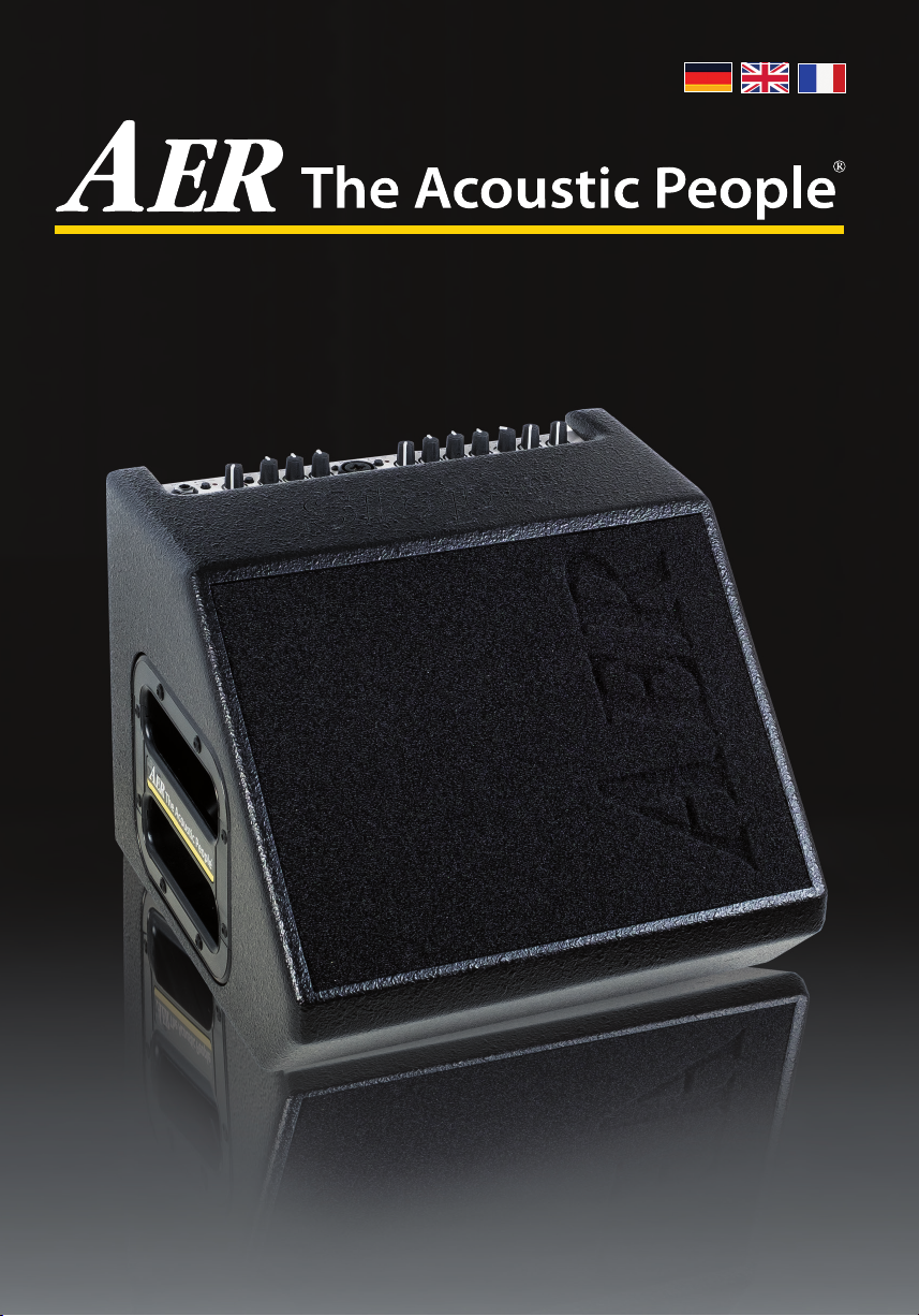
Compact Slope
Bedienungsanleitung, User Manual , Mode dèmploi 01/2017
1
Page 2
1. Einleitung
Willkommen bei
Wir freuen uns, dass Sie sich für den Compact Slope
entschieden haben.
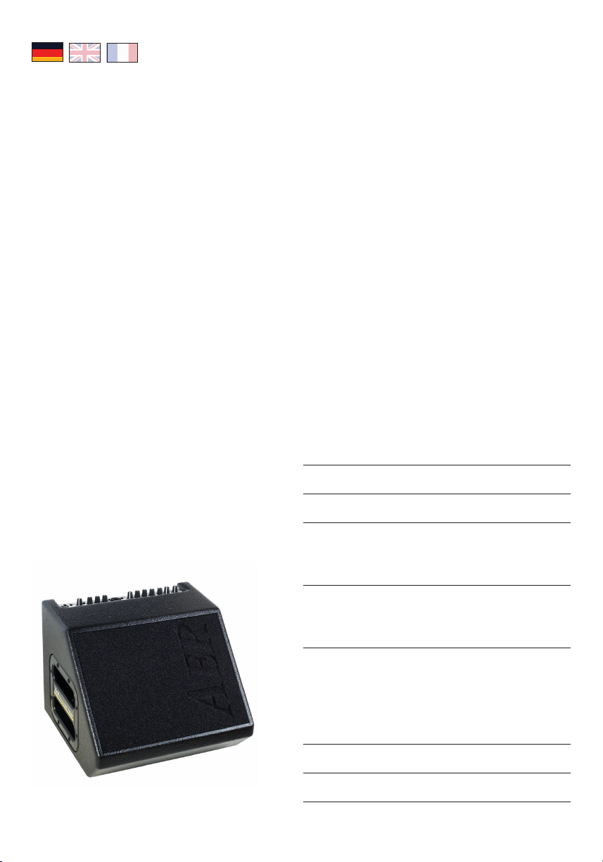
Der Compact Slope ist ein professionelles, kompaktes
und leistungsfähiges Verstärkersystem, das speziell für
die Verstärkung akustischer Instrumente entwickelt
worden ist, sich aber auch sehr gut für andere, auch
elektrische Instrumente eignet.
Bei der Konzeption stand für uns der Singer-/Songwriter im Vordergrund, der die gleichermaßen hervorragende Wiedergabe von Stimme und Instrument
verlangt und das in einem handlichen ’Paket’ mit
B!
Umhängetasche, sodass er auch mit öentlichen Verkehrsmitteln zum Gig anreisen kann und dabei durch
Klang und professionelle Ausstattung Publikum wie
Soundingenieure erstaunt.
Alle AER-Systeme sind dynamisch kontrolliert, das bedeutet für Sie absolute Zuverlässigkeit auch im Volllastbetrieb und das bei verblüend kleinen Abmessungen
und geringem Gewicht.
Wir wünschen Ihnen viel Spaß beim Einsatz Ihres
Compact Slope!
Compact Slope
Bedienungsanleitung
Inhalt Seite
1. Einleitung 2
2. Wichtige Sicherheitshinweise 3
3. Bedienungselemente und Anschlüsse 4
3.1 Frontseite 4
3.2 Rückseite 5
4. Inbetriebnahme 6
4.1 Anschließen und Einschalten 6
4.2 Aussteuern 6
5. Funktionsbeschreibung 6
5.1 Klangregelung 6
5.2 Eekte 7
5.3 Footswitch 7
5.4 Phantomspeisung 7
6. Technische Daten 8/9
7. Blockschaltbild 26
2
Page 3
2. Wichtige Sicherheitshinweise
Die folgenden Hinweise dienen der Minimierung des Verletzungsrisikos durch Feuer und Stromschlag.
CAUTION
RISK OF ELECTRIC SHOCK
DO NOT OPEN
ATTENTION
RISQUE DE CHOC ELECTRIQUE
NE PAS OUVRIR
Das Blitzsymbol im
gleichseitigen Dreieck
soll den Benutzer vor unisolierter, gefährlicher Spannung
innerhalb des Gehäuses dieses
Produkts warnen, die zu einem
elektrischen Schlag führen kann.
1. Lesen Sie diese Sicherheitshinweise aufmerksam,
bevor Sie das Gerät benutzen.
2. Bewahren Sie diese Sicherheitshinweise sorgfältig auf.
3. Beachten Sie alle Warnungen, Anweisungen und
zusätzliche Aufschriften auf dem Gerät.
4. Dieses Gerät wurde nur für den Betrieb unter
normalen klimatischen Bedingungen (gemäßigtes
Klima) entwickelt.
5. Installieren und verwenden Sie Ihren Verstärker
nicht in der Nähe von Wasser, oder wenn Sie selbst
naß sind.
6. Setzen Sie Ihr Gerät keinen plötzlichen großen
Temperaturschwankungen aus. Dies könnte
Kondenswasserbildung im Gerät hervorrufen und
es beschädigen. Im Fall von Kondenswasserbildung
lassen Sie bitte das Gerät vor der Benutzung vollkommen austrocknen.
7. Betreiben Sie Ihr Gerät an einem geschützten Ort,
wo niemand auf Kabel treten oder über sie stolpern
und sie beschädigen kann.
8. Achten Sie auf eine ungehinderte Belüftung des
Verstärkers, verdecken Sie nie Belüftungsönungen
oder -gitter.
9. Ziehen Sie immer den Netzstecker, wenn Sie den
Verstärker reinigen oder für längere Zeit nicht
benutzen. Verwenden Sie für die Reinigung ein
trockenes Tuch. Vermeiden Sie den Einsatz von
Putzmitteln und achten Sie darauf, daß keine Flüssigkeit in das Gerät eindringt.
10. Verwenden Sie nur passende Ersatzsicherungen
mit gleichem Nennstrom und gleicher Abschaltcharakteristik. Sicherungen niemals icken! Ziehen Sie
vor dem Ersetzen einer Sicherung den Netzstecker.
Brennt eine Sicherung nach kurzer Zeit erneut
durch, muß das Gerät überprüft werden.
11. Installieren Sie Ihren Verstärker nie in der Nähe von
Geräten mit starken elektromagnetischen Feldern,
wie großen Netztransformatoren, rotierenden
Maschinen, Neonbeleuchtung etc. Verlegen Sie
Signalkabel nicht parallel zu Netzkabeln.
12. Das Innere des Geräts enthält keine durch den
Benutzer zu wartenden Teile. Um eine Gefährdung
durch Stromschlag auszuschließen, darf das Gerät
Das Ausrufezeichen im
gleichseitigen Dreieck
soll den Benutzer auf
wichtige Hinweise zu Betrieb und
Instandhaltung (Service) dieses
Produkts in den beiliegenden
schriftlichen Unterlagen aufmerksam machen.
nicht geönet werden. Überlassen Sie Wartung,
Abgleich und Reparatur qualifziertem Fachpersonal.
Im Fall eines Fremdeingris erlischt die 2-jährige
Garantie.
13. Für die Einhaltung der EMV-Forderung müssen
geschirmte Kabel mit korrekt angeschlossenen
Steckverbindern für alle Signalanschlüsse verwendet werden.
14. Verwenden Sie immer einen geerdeten Netzanschluß mit der richtigen Netzspannung. Falls
Sie Zweifel haben, ob der Anschluß geerdet ist,
lassen Sie ihn durch einen qualifzierten Fachmann
überprüfen.
15. Verkabeln Sie Ihren Verstärker nur im ausgeschalteten Zustand.
16. Dieses Gerät muß in der Nähe einer Netzsteckdose eingesetzt werden und sich leicht vom Netz
trennen lassen. Der Netzstecker muß ohne weiteres
zugänglich sein. Achten Sie darauf, daß niemand
auf das Netzkabel tritt und daß es nicht eingeklemmt werden kann, insbesondere an Steckern,
Kabelkupplungen und an der Stelle, wo es aus dem
Gerät austritt.
17. Dieses Produkt kann bleibende Hörschäden
verursachen. Betreiben Sie es nicht für längere Zeit
mit hoher oder unangenehmer Lautstärke. Falls
Sie einen Hörverlust oder Klingeln in den Ohren
bemerken, sollten Sie einen Ohrenarzt aufsuchen.
18. Stellen Sie das Produkt nicht in der Nähe von
Wärme- quellen wie Heizkörpern oder anderen
Gegenständen, die Wärme abgeben, auf.
19. Stellen Sie keine Quellen von oenem Feuer, wie
Kerzen, auf das Gerät.
20. Achten Sie darauf, daß keine Gegenstände auf das
Gerät fallen und keine Flüssigkeiten durch Önungen in das Gehäuse gelangen. Stellen Sie sicher,
daß keine üssigkeitsgefüllten Gegenstände, wie
Vasen, auf das Gerät gestellt werden.
21. Stellen Sie dieses Gerät nicht auf einen
unstabilen Rollwagen, Ständer, Stativ,
Ausleger oder Tisch. Das Gerät kann
herunterfallen und ernsthafte Verletzungen verursachen oder selbst beschädigt
werden.
3
Page 4

3. Bedienelemente und Anschlüsse
IF_Compact603_20120529
3 3
2
1
5
4 4
6 67 8 8
10
9
11 12 13 14 15
Compact 603
3.1 Frontseite
1) input (ch. 1) Signaleingang-Buchse für 6,3 mm Mono-Klinkenstecker
2) high/low Eingangsempndlichkeits-Umschalter, Attenuator = aus = an
3) clip Übersteuerungsanzeige
4) gain Eingangspegel-Regler
5) colour Aktivierungsschalter Klangfarbenlter = nicht aktiv = aktiv
6) bass Basspegel-Regler
7) middle Mittenpegel-Regler
channels 1 + 2
8) treble Höhenpegel-Regler
9) input (ch. 2) Signaleingang-Kombibuchse für 6,3 mm Mono-Klinkenstecker
und XLR-male-Stecker
10) line/mic Signalquellen-Wahlschalter der Kombibuchse: line (nur über
Klinkenstecker) für Instrumente (Tonabnehmer) und andere
line-Quellen, mic (nur über XLR-Stecker) für Mikrofone
11) pan Eektsignalverteilungs-Regler
12) select Eektauswahlschalter
13) level Pegel-Regler interner Eekt
efx
4
14) power Ein-/Aus-Betriebszustandsanzeige
15) master Gesamtpegel-Regler
mains & master
Page 5
Compact 603
twin channel acoustic amplier
CA UT I O N
AT T E N T I O N
RISQUE DE CHOC ELECTRIQUE
line out
headphones
RISK OF ELECTRIC SHOCK
DO NOT OPEN
NE PAS OUVRIR
12345
send
tuner
footswitch
return
tip = int. efx
ring = ext. efx
on/o
power on
7
6
DI-out
1 = gnd
2 = pos
3 = neg
8
IB_Compact603_20120529
3.2 Rückseite
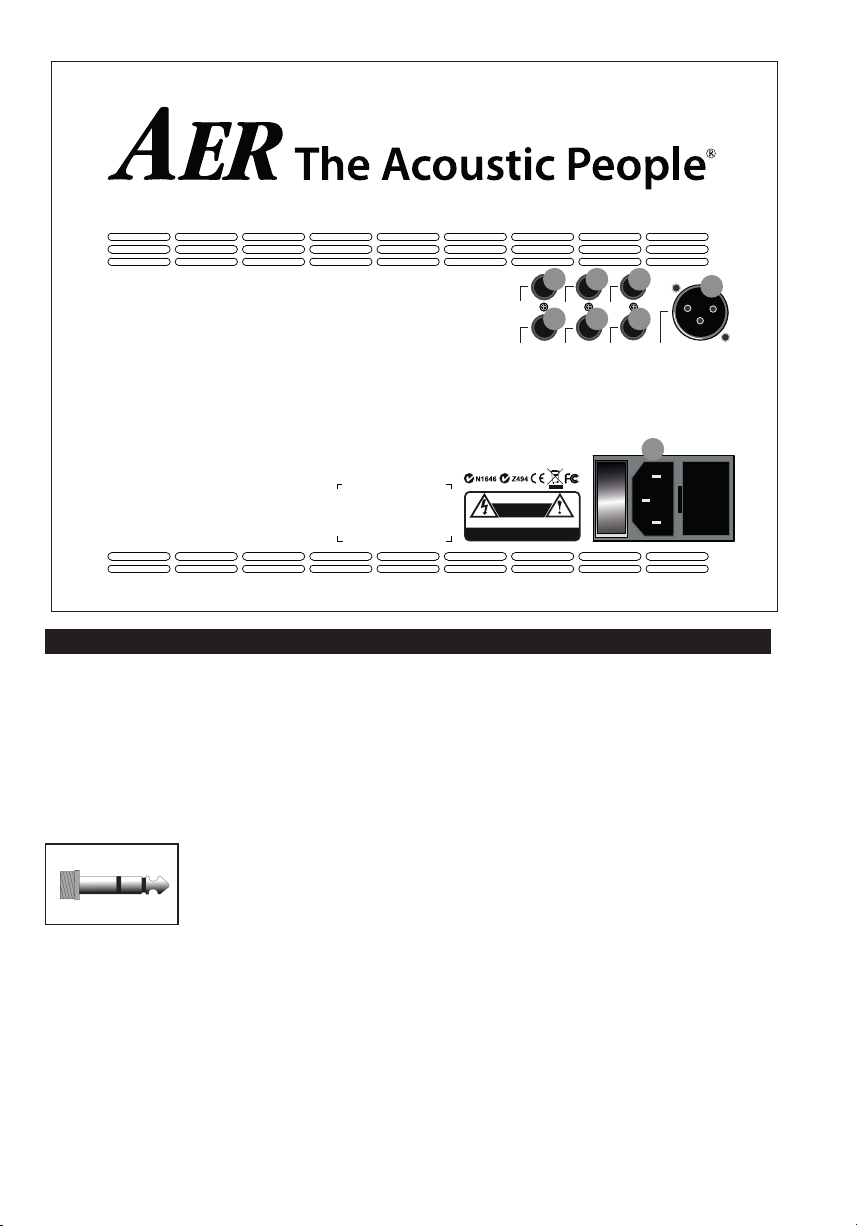
1) line out
Am line out liegt das Vorverstärkerausgangs-
signal nach Klangregelung, Eekten und master
zur Weiterleitung an andere Geräte an.
2) headphones
Dieser Ausgang dient zur Verwendung eines
Stereo-
Kopfhörers und schaltet dabei den
Lautsprecher stumm.
!!!
Achtung: Bitte verwenden
Sie ausschließlich Kopfhörer
mit Stereo-Klinkenstecker an
dieser Ausgangsbuchse !!!
3) send
Dieser Ausgang stellt die Verbindung zum Input
eines externen Eektgerätes her. Gemeinsam mit
return bildet send einen Eekteinschleifweg. Der
Eekt kann per Fußschalter ein- oder ausgeschaltet werden.
4) return
Return als Teil des Eekteinschleifweges stellt
den Signaleingang für ein externes Eektgerät
Made in Germany by
B
dar (vom Ausgang des Eektgerätes). Der Eekt
kann per Fußschalter ein- oder ausgeschaltet
werden. Return kann auch allein als quasi AuxiliarySignaleingang verwendet werden (-10 dbV).
5) tuner
Dieser Signalausgang (-9 dbV), der das Signal
vor dem master abgreift, ist zum Anschluss eines
Stimmgerätes vorgesehen.
6) footswitch
Anschlussbuchse für einen Doppel-Fußschalter
(Ein-/Aus-Schalter, tip = interner Eekt /
ring = externer Eekt an/aus).
7) DI-out
Der DI-out ist ein elektrisch symmetrierter Vorver-
stärkerausgang, pre master, pre Eekt, post EQ.
8) power on
Am power on Schalter der Netzkombination mit
integriertem Sicherungshalter schalten Sie den
Compact Slope an und aus.
5
Page 6
4. Inbetriebnahme
colour bass middle treble
colour bass middle treble
power
master
clip
colour
high
low
input
gain
bass middle treble efx level
alpha
channel 2
power
master
olour
bass middle treble efx level
alpha
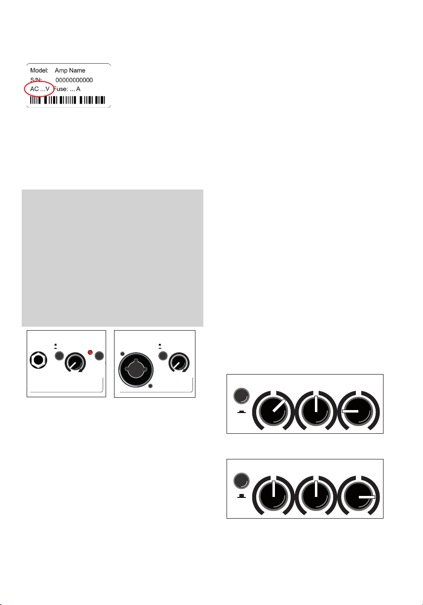
4.1 Anschließen und Einschalten
Prüfen Sie, ob die Netzspannung vor Ort
(z.B. 230 V in Europa,
120 V in den USA) mit
der zulässigen Netz-
übereinstimmt. Die entsprechenden Hinweise
und Sicherheitssymbole sind auf der Rückseite
des Gerätes angegeben. Stellen Sie danach alle
gewünschten Kabelverbindungen her und schalten
Sie das Gerät ein. Die grüne power-Kontrollleuchte
signalisiert Betriebsbereitschaft.
4.2 Aussteuern
Lassen Sie den Masterregler zunächst in Nullstel-
lung stehen. Spielen Sie zur Probe mit möglichst
kräftiger Lautstärke. Erhöhen Sie nach und nach
die ’gain’-Einstellung so weit wie möglich, achten
Sie dabei aber auf die rote ’clip’-Anzeige. Sie darf
während des Spiels nur ausnahmsweise (an den
lautesten Stellen)
aueuchten. Solange sie nicht aueuchtet, kann
’gain’ ggf. bis zum rechten Anschlag aufgedreht
werden.
Nachdem die richtige Gain-Einstellung gefunden
ist, bestimmen Sie mit dem ’master’-Regler die
gewünschte Endlautstärke.
high
input
gain
low
spannung des Gerätes
c
clip
input gain
line
mic
suchsweise auf die höchste Lautstärke. Nehmen
Sie ihn aber zurück, falls die ’clip’-Anzeige schon
bei niedrigster Gain-Einstellung aueuchtet.
• Stellen Sie immer sicher, dass Sie vollgeladene
Batterien in Ihrem PickUp System verwenden.
Oft ist dies der Grund für Brummen, Zischlaute
und Verzerrungen.
5. Funktionsbeschreibung
5.1 Klangregelung
Hnweis: Die aktive Klangregelung des
Compact Slope wirkt sich auch auf die Aussteuerung
aus. Wenn Sie bemerken, dass die clip-LED-Kontrollleuchte öfter aueuchtet, regeln Sie mit dem gainRegler entsprechend nach (s. 4.2 Aussteuern).
Die Klangregelung Ihres Compact Slope
(Drei-/Zweiband) ist eine aktive und hochwertige
Klangbeeinussung, die den natürlichen Ton von
Instrumenten und Stimme erhält und Ihnen die
Möglichkeit zur gezielten Akzentuierung bietet.
Bereits in Mittenstellung aller Regler erzeugt die
Elektronik ein sehr angenehmes, natürliches Klangbild, das Sie mit dem colour-Filter grundsätzlich
’färben’ können: dabei werden die Mitten abgesenkt
und die Höhen angehoben (-3 dB bei 700 Hz, +10 dB
bei 8kHz). Der Ton wird oener, leichter und eignet
sich besonders für Zupftechniken.
Die Klangregelung kann die Wirkung des colour-Filters unterstützen oder mildern und lässt dabei eine
unterschiedliche Mittenbetonung zu. (s. Abb. unten)
channel 2
• Mit den Gain-Reglern passen Sie unterschiedliche PickUp Systeme, bzw. Signalquellen an den
Compact Slope an an, um die bestmögliche
Tonwiedergabe zu erreichen.
• Wenn die Gain-Einstellung zu niedrig ist, kann
der Compact Slope nicht optimal arbeiten. Die
maximale Lautstärke wird nicht erreicht und das
Verhältnis zwischen Signal zund Rauschen wird
schlechter.
• Bei zu hoher Gain-Einstellung treten hörbare Verzerrungen auf. Durch die ’clip’-Leuchte werden
Sie davor rechtzeitig gewarnt.
• Wenn das Instrument einen Lautstärke-Regler
besitzt, stellen Sie diesen zum Aussteuern ver-
6
channel 1
A: mit colour-Filter (Schalter gedrückt)
treble reduzieren um evtl. Schärfe abzumildern
B: ohne colour-Filter (Schalter nicht gedrückt)
treble anheben um den Ton zu önen
Page 7

5.2 Eekte
Der Compact Slope verfügt über einen
eingebauten (internen) digitalen Eektprozessor.
Mit dem select-Schalter können Sie zwischen
4 unterschiedlichen Eekten wählen:
1 = reverb 1 (short)
2 = reverb 2 (long)
3 = delay (320 ms)
4 = chorus
Der efx-level-Regler bestimmt den Anteil des
gewählten internen Eekts am Originalsignal
(Linksanschlag = kein Eekt).
Darüberhinaus kann ein zusätzliches Eektgerät
(externer Eekt) an den Compact Slope angeschlossen werden. Benutzen Sie dazu bitte die auf
der Rückseite des Gerätes bendlichen Buchsen
send und return (send zum Input, return vom Output des ext. Eektes). Regeln Sie den Eektanteil
des eingeschleiften Eekts am externen Eektgerät.
Mit dem efx-pan-Regler können Sie den Kanälen
stufenlos unterschiedliche Eektanteile zumischen.
Dabei gilt:
Linksanschlag: interner Eekt auf channel 1
externer Eekt auf channel 2
Mittelstellung: interner Eekt auf channel 1 + 2
externer Eekt auf channel 1 + 2
Rechtsanschlag: interner Eekt auf channel 2
externer Eekt auf channel 1
5.3 Footswitch
An die footswitch-Buchse auf der Rückseite des
Gerätes kann mit einem Stereokabel ein StandardDoppelfußschalter (An-/Aus-Schalter) angeschlossen werden. Mit diesem werden der interne und der
externe Eekt ein/aus geschaltet.
5.4 Phantomspeisung
Mikrofone, die eine 48-V-Phantomspeisung erfordern, können direkt an der XLR-Buchse von input
1 angeschlossen werden. Die Phantomspeisung ist
im Auslieferungszustand aktiviert, kann aber durch
eine interne Steckbrücke deaktiviert werden.
An input 2 kann nachträglich eine 9-V-Phantomspeisung durch eine interne Steckbrücke aktiviert
werden.
Bitte beachten Sie: Für die beiden o.g. Eingrie
muss das Gerät geönet werden, deshalb dürfen
diese Änderungen an der De-/Aktivierung der
Phantomspeisung nur in einer Fachwerkstatt durchgeführt werden.
Hinweis zur Benutzung von Phantom-Power
(Phantom-Power = Fernspeisung, hier: Spannungsversorgung eines Audiogerätes durch die
angeschlossene Audiokabelverbindung)
Schließen Sie nur Geräte an, die für die Verwendung
von Phantomspeisung geeignet sind!
Generell geeignet sind Geräte mit Phantomspeisung. Diese Geräte sind entsprechend gekennzeichnet, achten Sie dabei auf die zulässige Stromaufnahme (siehe tech. Daten).
Hochwertige dynamische Mikrofone mit symmetrischer Signalführung benötigen zwar keine
Phantom-Power, können aber damit ’leben’.
Bei anderen Geräten, die nicht explizit für den
Betrieb mit Phantom-Power konzipiert wurden,
können erhebliche Störungen und auch Schäden
auftreten.
Beispiele:
Einfache dynamische Mikrophone mit Mono-Klin-
kenstecker (unsymmetrische Signalführung), die
nachträglich durch einen XLR-Stecker modiziert
worden sind.
Audiogeräte mit symmetrischem XLR-Ausgang (z.B.
DI-Boxen, Eektgeräte, Instrumentenvorverstärker
mit DI-Ausgang etc.), die nicht gegen an ihrem XLRAusgang anliegende Phantom-Power geschützt
sind.
Andere Audiogeräte (z.B. Vorverstärker, Eektpedale etc.), deren unsymmetrischer Line-Ausgang
durch einen XLR-Stecker modiziert worden ist.
Bei Unsicherheit erkundigen Sie sich bitte beim
Hersteller des von Ihnen verwendeten Gerätes.
Wir wünschen Ihnen viel Spaß mit Ihrem Compact Slope!
7
Page 8

6. Technische Daten
channel 1 Line / instrument input, high impedance,
clip indicator
channel 2 Switchable input with line mode and
line / instrument mode (jack input only)
mic mode (jack or XLR)
clip indicator Headroom: 6 dB
return Return input from external parallel eect loop,
line out Preamplier output after master, tone master
8
unbalanced Mono jack socket, 1⁄4“ (6.35 mm)
Nom. input voltage: 100 mV (–20 dBV)
High/low (attenuator) switch: –10 dB Min.
input voltage: high: 22 mV (–33 dBV)
low: 68 mV (–23 dBV)
Max. input voltage (THD = 1%):
high: 3.5 V (+11 dBV)
low: 5 V (+14 dBV)
Input impedance: 2.2 M || 350 pF
Signal / noise ratio (A-weighted):
95 dB Equivalent input noise voltage
(A- weighted): 1.8 V (– 115 dBV)
Phantom power: Optional (see notes),
9 V DC / max. 100 mA, on ring of input jack,
short circuit protected
Headroom: min. 6 dB
microphone mode Combo socket, XLR + jack
1⁄4” (6.35 mm)
Line / instrument input, high impedance,
unbalanced
Nom. input voltage: 100 mV (–20 dBV) Min.
input voltage: 27 mV (–31 dBV)
Max. input voltage: 7 V (+17 dBV)
Input impedance: 2.2 M || 350 pF
Signal / noise ratio (A-weighted): 92 dB
Equivalent input noise voltage
(A- weighted): 2.7 V (– 111 dBV)
Microphone input, XLR (balanced), stereo jack
(balanced), or mono jack (unbalanced)
1 / sleeve = ground, 2 / tip = positive (+), 3 /
ring = negative (–) Nom. input voltage: 10 mV
(–40 dBV) Min. input voltage: 3.3 mV (–50 dBV )
with option: 5.8 mV (–45 dBV) (see notes)
Max. input voltage: 1 V (0 dBV)
with option: 1.6 V (+4 dBV)
Input impedance (balanced): 1.2 k Input
impedance (unbalanced): 2.7 k Voice lter:
–10 dB at 270 Hz referred to 10 kHz Signal /
noise ratio (A-weighted): 80 dB Equivalent
input noise voltage (A- weighted):
1 V (–120 dBV)
Phantom power: 48 V, XLR only, R = 6.8 k
per terminal, max. 10 mA total, short- circuit
protected (see notes)
or supplementary input
Mono jack, 1⁄4” (6.35 mm)
Nom. input voltage: 320 mV (–10 dBV)
Max. input voltage: 5 V (+14 dBV)
Input impedance: 20 k
controls, and eects
Mono jack, 1⁄4” (6.35 mm)
Nom. output voltage: 700 mV (–3 dBV)
Output impedance: 100
Min. load impedance: 2 k
Residual noise (A-weighted):
4.5 V (–107 dBV)
headphones Headphones output. When plugged in, the
internal speaker is switched o.
Stereo jack socket, 1⁄4” (6.35 mm)
Nominal, no-load, output voltage
15.5 V (+24 dBV)
Output impedance (per channel): 940
Load impedance: 8...2000
Nom. output power (THD < 1%):
2 x 2 mW / 8
2 x 50 mW / 2000 Residual noise
(A-weighted): 2.7 V (–111 dBV) / 8
220 V (–73 dBV) / 2000
Note: For headphones with stereo (TRS) jack
only. Not functional with mono jacks.
send Output for external parallel eect loop,
before master, after tone controls Mono jack,
1⁄4” (6.35 mm)
Nom. output voltage (efx pan centered):
300 mV (–10 dBV)
Output impedance: 47
Min. load impedance: 2 k
tuner Tuner output, after tone controls, before
eects and master
Mono jack, 1⁄4” (6.35 mm)
Nom. output voltage: 100 mV (–20 dBV)
Output impedance: 47
Min. load impedance: 2 k
DI-out Balanced, non-isolated XLR output, after tone
controls, without eects
1 = ground
2 = positive (+)
3 = negative (–)
Nom. output voltage (dierential):
41 mV (–28 dBV)
Output impedance per terminal referred to
ground: 47
Min. load impedance (dierential): 1 k
footswitch Connector for a dual footswitch
Stereo jack, ¼” (6.35 mm)
tip = internal eect on/o
ring = external eect on/o
sleeve = common (ground)
Function: Switch ON = eect OFF
Tone controls
channel 1 colour –3 dB at 700Hz, +10dB at 8 kHz
bass ±8 dB at 100 Hz, shelf type
middle ±6 dB at 800 Hz
treble ±8 dB at 10 kHz, shelf type
channel 2 bass ±8 dB at 100 Hz, shelf type
treble ±11dB at 10 kHz, shelf type
Page 9

6. Technische Daten
Eects
Internal eect Digital eect processor
1 Reverb with short predelay
2 Reverb with long predelay
3 Delay (320ms, repetitive)
4 Chorus
Parallel eect loop, see send and return
efx pan Blends both internal and external eects bet-
ween channels 1 and 2, with reverse direction
of rotation for the external eects
Power amp
Construction Monolithic IC with DMOS output
Output power 60 W / 4 ohms (THD = 1%)
Continuous output power is determined
by limiter, see limiter threshold.
General
Distortion THD + N < 0.1% (6 W / 4 W),
measured at loudspeaker terminals
Noise Residual noise (A-weighted SPL):
approx. 17 dB (A) / 1 m
See also inputs and outputs for noise data.
Analog signal
processing Subsonic lter, adaptive peak limiter
Limiter
threshold 50 W / 4 ohms
Speaker system 8” (200 mm) dual cone full-range
speaker, bass reex enclosure
Mains power Mains voltage (depending on model):
100, 120, 220, 230, or 240 V~, 50–60 Hz
Power consumption: max. 120 W
Mains fuse Size: 5 x 20 mm
For 220, 230, 240 V models: T 1A L 250V
For 100, 120 V models: T 2A L 250V
Operating 0…35 °C
temperature range
Cabinet 12 mm (0.47”) birch plywood
Finish Waterbased acrylic, black spatter nish
Dimensions and weight
Dimensions 259 mm (10.19“) high
311 mm (13.04“) wide
137/235 mm (5.39"/12.84"“) deep
Weight 7,2 kg (15.87 lbs)
DEFINITIONS
Rated conditions
· Nominal input voltage at input under test
· master fully clockwise
· high / low and colour o
· bass / middle / treble / pan centered
· gain of unused inputs and efx level fully anticlockwise
· gain of input under test adjusted to nominal output
voltage at line out. (This condition corresponds by design
to the rated output power.)
Nominal input voltage: Standard condition for specications,
if not stated otherwise.
Minimum input voltage: Input voltage required for nominal
output with maximum gain and volume settings.
Maximum input voltage: Input voltage that does not cause
distortion more than rated THD+N, suitable control settings
provided.
Nominal output voltage or power refers to rated conditions.
THD + N: Total harmonic distortion + noise, input
voltage reduced by 10 dB after setting up rated
conditions.
Signal / noise ratio: Ratio of output voltage at rated
conditions to output noise voltage with input shorted.
Equivalent input noise voltage: Noise voltage at loudspeaker
terminals divided by gain of amplier. Input shorted after
setting up rated conditions.
Residual noise: Output noise with minimal gain and volume
settings.
Adaptive limiter: Adaptive with respect to power supply.
Maintains constant headroom regardless of power supply
uctuations.
General: Signal voltages are RMS values. Test signal sine 1 kHz
sine unless stated otherwise. Noise measured from 20 Hz to
20 kHz. Noise stated for a specic input implies that all other
inputs are not used. Sound pressure level (SPL) based on loudspeaker specication by manufacturer.
Specications and appearance subject to change without
notice.
TD20160511 (Compact 60/3)
Notes
Options congurable by internal jumpers (refer
modication to qualied personnel):
· 9 V phantom power for channel 1.
Caution: Phantom power may damage external
equipment. Read the notes in the operating
instructions.
· Low-gain option (more headroom) for mic input
· Deactivation of 48 V phantom power for mic input
9
Page 10
1. Introduction
Welcome to B!
Thank you for choosing the Compact Slope.
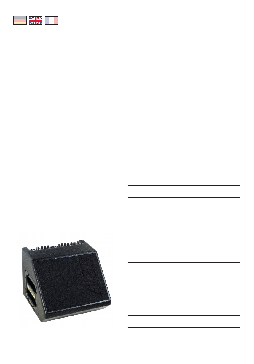
The Compact Slope is a professional, compact and
powerful amplier system. Especially developed for the
enhancement of acoustic instruments it is nonetheless
suitable for other instruments, even electrical ones.
Our design concept was focused on the singer-/songwriter who requires outstanding reproduction of his/
her instrument and vocals yet needs a handy-unit
with gigbag which is easily portable (even via public
transport). We sought to produce an amp that would
accomplish this while astonishing audiences as well as
sound-engineers through excellent sound and professional instrumentation.
All AER-systems are subtly dynamically controlled,
which ensures absolute reliability in full load operation
despite strikingly small sizes and little weight.
Read on and have fun using your Compact Slope!
Compact Slope
User Manual
Content Page
1. Introduction 10
2. Important Safety Instructions 11
10
3. Controls and connections 12
3.1 Front side 12
3.2 Rear side 11
4. Starting up 12
4.1 Cabling and switching on 12
4.2 Level adjustment 13
5. Functional characteristics 14
5.1 Tone control 14
5.2 Eects 15
5.3 Footswitch 15
5.4 Phantom powering 15
7. Technical specs 16/17
6. Circuit diagram 26
Page 11
2. Important Safety Instructions
The following guidelines shall help minimize the risk of injury through re or electric shock.
CAUTION
RISK OF ELECTRIC SHOCK
DO NOT OPEN
ATTENTION
RISQUE DE CHOC ELECTRIQUE
NE PAS OUVRIR
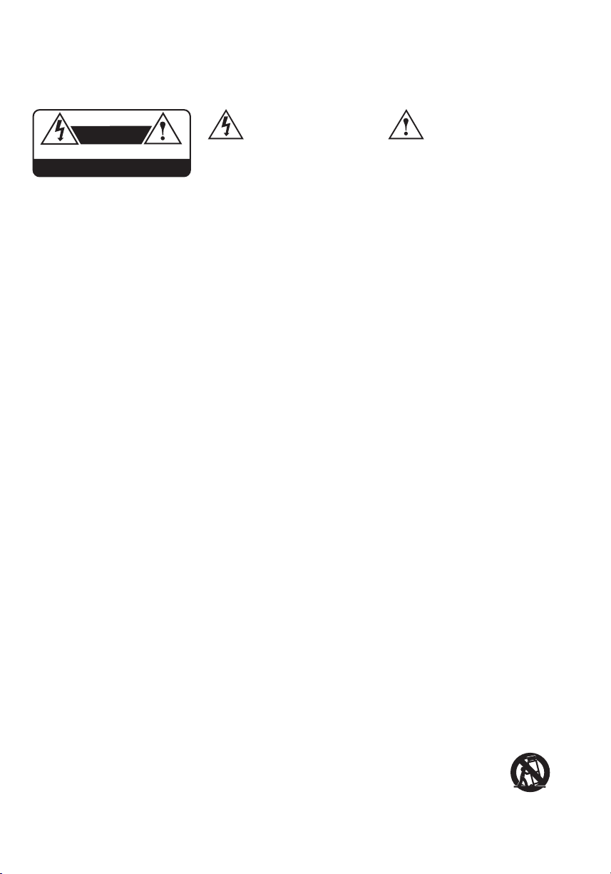
The lightning ash with
the arrow head symbol
within an equilateral
triangle is intended to alert the
user to the presence of unisolated
´dangerous voltage´ within this
product´s enclosure that may
be of sucient magnitude to
constitute a risk of electric shock
to persons.
1. Carefully read these safety notes before you use the
device!
2. Keep these safety notes in a safe place.
3. Pay attention to all warnings, instructions and additi
onal texts on the unit.
4. This device was only designed for operation under
normal climatic conditions (temperate climate).
5. Do not install or use your amp in close proximity to
water or if you are wet yourself.
6. Do not subject your device to sudden and severe
temperature changes. This could cause moisture
condensation inside the unit, which could damage
it. In the event of moisture condensation allow the
device to dry out completely before use.
7. Use your amp in a safe place where nobody can step
on cables or trip over and damage them.
8. Pay attention to an unhindered air circulation
around the amp, never obstruct the air vents or grilles.
9. Always pull the mains plug before cleaning your
amp or when left unused for a long period of time.
Use only a dry cloth for cleaning. Avoid the use of
detergents and do not let any liquids seep into the
unit.
10. Use only the right fuses with the same current
rating and trigger characteristic as replacements. Ne
ver mend fuses! Pull the mains plug before replacing
a fuse. Should a fuse blow again after a short while,
the device needs to be checked.
11. Never install your amp close to devices with strong
electromagnetic elds such as large mains transfor
mers, revolving machines, neon illumination etc. Do
not lay signal cables parallel to power current cables.
12. There are no user-serviceable components inside the
unit. To avoid the risk of an electric shock, the unit
must not be opened. All maintenance, adjustment
and repair works should be carried out by qualied
-
The exclamation point
within an equilateral
triangle is intended to
alert the user to the presence
of important operating and
maintenance (servicing)
instructions in the literature
accompanying this product.
sta only. Any unauthorized tampering will void the
2-year warranty.
13. In keeping with the EMV regulations screened cables
-
-
with correctly tted connectors must be used for all
signal connections.
14. Always use an earthed power supply with the
correct mains voltage. If you are in doubt about the
power outlet ground, have it checked by a qualied
technician.
15. Cable up your amp only when it is powered o.
16. This device should be installed near the socket out
let and disconnection of the device should be easily
accessible. The mains plug of the power
supply shall remain readily operable. Protect the
power cord from being walked on or pinched par
ticularly at plugs, convenience receptacles and the
point where they exit from the apparatus.
17. This product may cause permanent hearing loss.
Do not operate for long periods of time at a high
volume level or at any level that is uncomfortable.
If you experience any hearing loss or ringing in the
ears, you should consult an audiologist.
18. The product should be located away from heat
sources such as radiators, heat registers or other
products that produce heat.
19. Do not place any open sources of re, like candles,
on the device.
20. Care should be taken so that objects do not fall onto
the device and liquids are not spilled into the enclo
sure through openings. Ensure that no objects lled
with liquids, such as vases, are placed on the device.
21. Do not place this device on an unstable cart, stand,
tripod, bracket or table. The device may fall, causing
serious injury to you and serious damage
to the device itself.
-
-
-
11
Page 12
3. Controls and connections
1
IF_Compact603_20120529
3 3
2
5
4 4
6 67 8 8
9
10
11 12 13 14 15
Compact 603
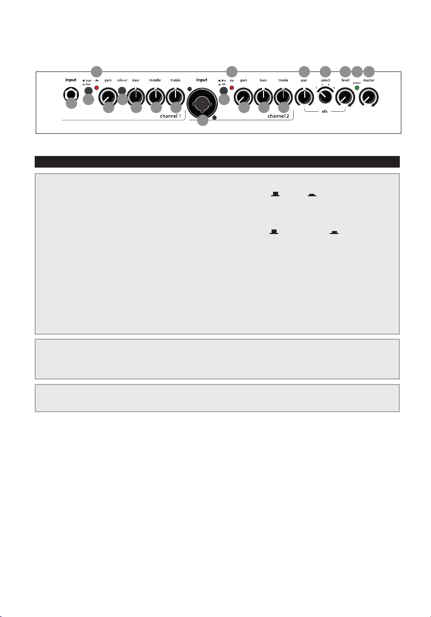
3.1 Front side
1) input (ch. 1) signal input, socket for 6,3 mm mono jackplug
2) high/low input sensitivity switch, attenuator = o = on
3) clip overload indicator
4) gain input level control
5) colour tone colour lter activation switch = not active = active
6) bass bass frequency level control
7) middle middle frequency level control
channels 1 + 2
8) treble treble frequency level control
9) input (ch. 2) signal input, combo-socket for 6,3 mm mono jackplug and
XLR-connectors
10) line/mic signal source selector switch: line (only via jackplug)
for instruments (pickup) and other line level sources,
mic (only via XLR-connector) for microphones
11) pan eect signal distribution control
12) selec t eect select switch
13) level level control internal eect
efx
14) power on/o status indicator
15) master master level control
12
mains & master
Page 13
Compact 603
twin channel acoustic amplier
AT T E N T I O N
RISQUE DE CHOC ELECTRIQUE
line out
headphones
CA UT I O N
RISK OF ELECTRIC SHOCK
DO NOT OPEN
NE PAS OUVRIR
12345
send
tuner
footswitch
return
tip = int. efx
ring = ext. efx
on/o
power on
7
6
DI-out
1 = gnd
2 = pos
3 = neg
8
Made in Germany by
IB_Compact603_20120529
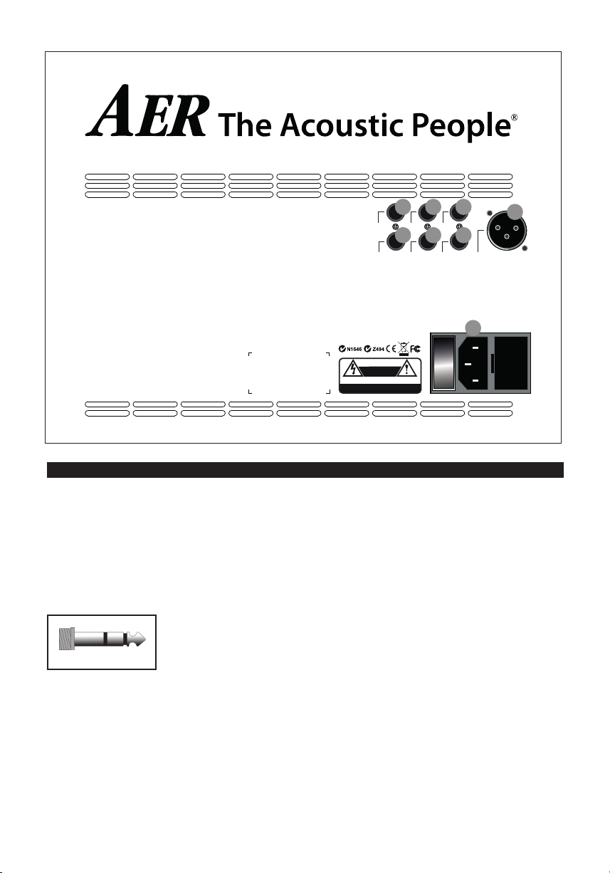
3.2 Rear side
1) line out
The line out supplies a pre-amp signal taken
after tone-control, eects and master for forwarding to other appliances.
2) headphones
This output enables you to connect stereo head-
phones and mutes the loudspeaker.
!!!
Warning: Only use
headphones with stereo
jackplugs in this output
socket !!!
3) send
Send is an output to connect to an external
eect device and in conjunction with return
(input) forms a loop here designed as external
eect loop. The eect can be switched on or o
via footswitch.
4) return
Return as part of the eect loop operates as
B
signal input from an external eect device (from
output of the eect device). The eect can be
switched on or o via footswitch. Return on its
own can also be used as quasi auxiliary signal
input (-10 dbV).
5) tuner
The tuner output supplies a pre-master signal
(-9 dbV) to connect an external tuner to the
Compact 60
3.
6) footswitch
Connection socket for a double-footswitch (on-/
o-switch, tip = internal eect/ring = external
eect on/o).
7) DI-out
Preamp-output with symmetrical signal, after
tone-control, pre master, without eects.
8) power on
Combined mains switch with mains socket and
fuse holder.
13
Page 14
4. Starting up
colour bass middle treble
colour bass middle treble
power
master
clip
colour
high
low
input
gain
bass middle treble efx level
alpha
channel 2
power
master
olour
bass middle treble efx level
alpha
4.1 Cabling and switching on
Before connecting to
mains, please ensure
that your local mains
voltage is suitable for
the voltage of the device (e.g. 120V in the
USA, 230V in Europe).
The relevant specs and safety symbols are printed
on the rear side of the unit.
Connect all cables according to your application
and switch the amplier on. The green power con-
trol LED indicates operational readiness.
4.2 Level adjustment
Note: Level adjustment
By setting the level correctly we mean the signal
level in one or several devices in a signal chain is
neither too high nor too low. This applies equally
to all circuits in a complete circuit design (EQs,
preamps etc.)
Consequently, care must be taken that no part of
the circuit is overloaded or that distortion is unintentionally added to the signal.
We have carefully designed the circuit to achieve
this objective whilst also providing controls for
„manual“ intervention.
optimal and distortion-free performance.
Finally set the desired overall volume level with the
master level control.
5. Functional characteristics
5.1 Tone control
The triple-band equalizer of your Compact Slope
provides you with an active and high quality sound
interaction tool that supports the natural tone of instruments and voice whilst simultaneously oering
you the possibility of a controlled accentuation.
With all controls in mid position the lters are set to
produce a very pleasing and natural sound impression that you can „colour up“ by using the colour
lter with the eect of lowering the mids and
lifting the trebles. The tone becomes more open
and light and is especially suited for ngerpicking
techniques.
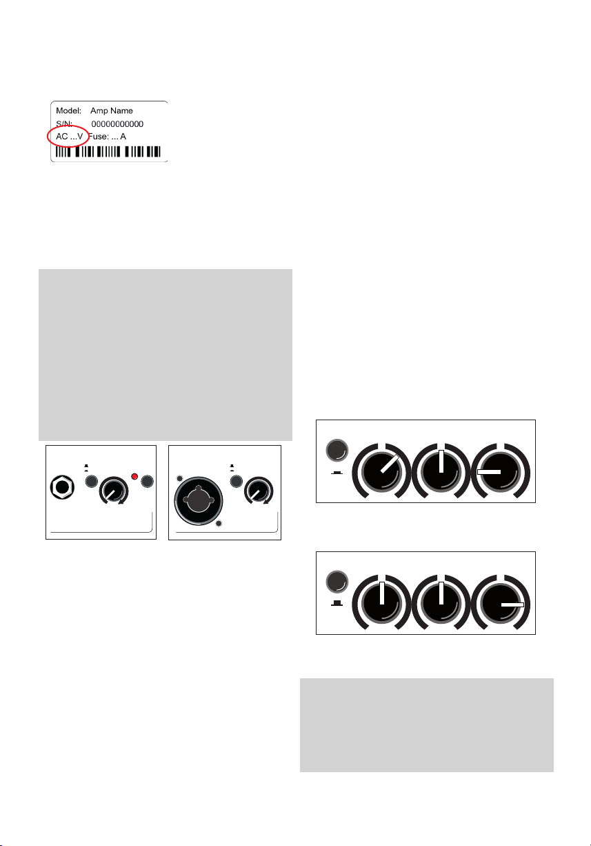
The equalization can support or soften the eect of
the colour lter and allows a dierentiated midsaccentuation.
input
high
low
gain
clip
channel 2
c
First ensure, that the master level control is zeroed
(over to far left), so that when you are setting the
sound level, the signal passes through the electronics only and does not reach the loudspeaker.
By pressing the high-/low- (attn.) resp. line-/mic-
switches you can adapt the amplier to your signal
sources (guitar pickups, microphone etc).
Turn the gain control clockwise until the red clip
indicator ashes momentarily when playing with a
strong attack. Thus you make sure that your signal
source (e.g. instrument) provides the input-stage of
the amplier with the necessary input
The clip-LED indicates an overload. A short icker
is of no danger to AER devices. During operation a
short icker can be accepted, to be on the safe side
you should reduce the gain slightly to achieve an
14
input gain
line
mic
channel 1
A: with colour-lter (switch pressed)
reduce treble to soften possible sharpness
B: without colour-lter (switch not pressed)
boost treble to brighten the sound
Note:
The active equalization of the Compact Slope eects the
signal adjustment. If you spot an intensied ickering of
the clip indicator, readjust the signal level with the gain
control (s. 4.2 Level adjustment).
Page 15

5.2 Eects
The Compact Slope has a built-in (internal) digital
eect processor, with the select-switch you can
choose between
4 dierent eects:
1 = reverb 1 (short)
2 = reverb 2 (long)
3 = delay (320 ms)
4 = chorus
The efx-level-control determines the intensity of
the internal eects (left stop = no eect).
Furthermore an additional eects unit (external effect) may be connected to the Compact Slope. For
this purpose use the send and return sockets on
the rear side of the amplier (send goes to input,
return to the output of the external eects device).
The intensity of the eect is adjusted at the external
eects unit.
With the efx-pan control the dierent eects are
blended with the original signal. The efx-pan works
as follows:
left stop: internal eect on channel 1
external eect on channel 2
mid position: internal eects on channels 1 + 2
external eects on channels 1 + 2
right stop: internal eects on channel 2
external eects on channel 1
5.3 Footswitch
A standard double-footswitch (on-/o-switch)
can be plugged into the footswitch-socket on the
rear side of the amplier via stereo cable. By this
footswitch the internal and external eects can be
switched on and o.
5.4 Phantom power
Microphones requiring 48 V-phantom power
can be connected to the XLR-socket of channel
2 directly. Factory-provided phantom power is
activated but, if required, may be deactivated by an
internal jumper.
In contrary 9 V-phantom power, if required, can
additionally be activated in channel 1 by an internal
jumper.
Please note: For both alterations the device must
be opened, therefore only qualied service personnel may carry out the modications concerning the de-/activating of phantom power.
General Note:
Use of 48 V or 24 V phantom power
(Phantom power = remote supply, here: powering an audio device via the connected audio
line)
Turn on the phantom power only if the unit
connected to an XLR socket that is designed to
handle it!
In general, suitable units are e.g. condenser
microphones, active DI-boxes and other special
audio devices, whose power supply is drawn
from the phantom power. Such devices are also
labelled accordingly; please heed the permissible power consumption (max.10mA).
High-quality dynamic microphones with a balanced signal need no phantom power, but can
handle it anyway.
Other devices, which have not been designed
explicitly for phantom power operation, can suffer from considerable malfunctions and damage
may result as well.
Examples of devices that may be damaged
by incorrect application of phantom power
include:
Low-cost dynamic microphones with a mono
jackplug (unbalanced signal) that were tted
afterwards with an XLR connector.
Audio devices with a balanced XLR output (e.g.
DI-boxes, eects devices, instrument preamps
with a DI output etc.) which are not protected
against phantom power applied to their XLR
output. (The DI connectors on AER products are
protected against applied phantom power.)
Other audio devices (such as preamps, eects
pedals etc.) whose unbalanced line output was
replaced by an XLR socket.
If in doubt please consult the manufacturer of
the device you are using.
We wish you lots of fun playing your Compact Slope!
15
Page 16

6. Technical specications
channel 1 Line / instrument input, high impedance,
clip indicator
channel 2 Switchable input with line mode and
line / instrument mode (jack input only)
mic mode (jack or XLR)
clip indicator Headroom: 6 dB
return Return input from external parallel eect loop,
line out Preamplier output after master, tone master
16
unbalanced Mono jack socket, 1⁄4“ (6.35 mm)
Nom. input voltage: 100 mV (–20 dBV)
High/low (attenuator) switch: –10 dB Min.
input voltage: high: 22 mV (–33 dBV)
low: 68 mV (–23 dBV)
Max. input voltage (THD = 1%):
high: 3.5 V (+11 dBV)
low: 5 V (+14 dBV)
Input impedance: 2.2 M || 350 pF
Signal / noise ratio (A-weighted):
95 dB Equivalent input noise voltage
(A- weighted): 1.8 V (– 115 dBV)
Phantom power: Optional (see notes),
9 V DC / max. 100 mA, on ring of input jack,
short circuit protected
Headroom: min. 6 dB
microphone mode Combo socket, XLR + jack
1⁄4” (6.35 mm)
Line / instrument input, high impedance,
unbalanced
Nom. input voltage: 100 mV (–20 dBV) Min.
input voltage: 27 mV (–31 dBV)
Max. input voltage: 7 V (+17 dBV)
Input impedance: 2.2 M || 350 pF
Signal / noise ratio (A-weighted): 92 dB
Equivalent input noise voltage
(A- weighted): 2.7 V (– 111 dBV)
Microphone input, XLR (balanced), stereo jack
(balanced), or mono jack (unbalanced)
1 / sleeve = ground, 2 / tip = positive (+), 3 /
ring = negative (–) Nom. input voltage: 10 mV
(–40 dBV) Min. input voltage: 3.3 mV (–50 dBV )
with option: 5.8 mV (–45 dBV) (see notes)
Max. input voltage: 1 V (0 dBV)
with option: 1.6 V (+4 dBV)
Input impedance (balanced): 1.2 k Input
impedance (unbalanced): 2.7 k Voice lter:
–10 dB at 270 Hz referred to 10 kHz Signal /
noise ratio (A-weighted): 80 dB Equivalent
input noise voltage (A- weighted):
1 V (–120 dBV)
Phantom power: 48 V, XLR only, R = 6.8 k
per terminal, max. 10 mA total, short- circuit
protected (see notes)
or supplementary input
Mono jack, 1⁄4” (6.35 mm)
Nom. input voltage: 320 mV (–10 dBV)
Max. input voltage: 5 V (+14 dBV)
Input impedance: 20 k
controls, and eects
Mono jack, 1⁄4” (6.35 mm)
Nom. output voltage: 700 mV (–3 dBV)
Output impedance: 100
Min. load impedance: 2 k
Residual noise (A-weighted):
4.5 V (–107 dBV)
headphones Headphones output. When plugged in, the
internal speaker is switched o.
Stereo jack socket, 1⁄4” (6.35 mm)
Nominal, no-load, output voltage
15.5 V (+24 dBV)
Output impedance (per channel): 940
Load impedance: 8...2000
Nom. output power (THD < 1%):
2 x 2 mW / 8
2 x 50 mW / 2000 Residual noise
(A-weighted): 2.7 V (–111 dBV) / 8
220 V (–73 dBV) / 2000
Note: For headphones with stereo (TRS) jack
only. Not functional with mono jacks.
send Output for external parallel eect loop,
before master, after tone controls Mono jack,
1⁄4” (6.35 mm)
Nom. output voltage (efx pan centered):
300 mV (–10 dBV)
Output impedance: 47
Min. load impedance: 2 k
tuner Tuner output, after tone controls, before
eects and master
Mono jack, 1⁄4” (6.35 mm)
Nom. output voltage: 100 mV (–20 dBV)
Output impedance: 47
Min. load impedance: 2 k
DI-out Balanced, non-isolated XLR output, after tone
controls, without eects
1 = ground
2 = positive (+)
3 = negative (–)
Nom. output voltage (dierential):
41 mV (–28 dBV)
Output impedance per terminal referred to
ground: 47
Min. load impedance (dierential): 1 k
footswitch Connector for a dual footswitch
Stereo jack, ¼” (6.35 mm)
tip = internal eect on/o
ring = external eect on/o
sleeve = common (ground)
Function: Switch ON = eect OFF
Tone controls
channel 1 colour –3 dB at 700Hz, +10dB at 8 kHz
bass ±8 dB at 100 Hz, shelf type
middle ±6 dB at 800 Hz
treble ±8 dB at 10 kHz, shelf type
channel 2 bass ±8 dB at 100 Hz, shelf type
treble ±11dB at 10 kHz, shelf type
Page 17

6. Technical specications
Eects
Internal eect Digital eect processor
1 Reverb with short predelay
2 Reverb with long predelay
3 Delay (320ms, repetitive)
4 Chorus
Parallel eect loop, see send and return
efx pan Blends both internal and external eects bet-
ween channels 1 and 2, with reverse direction
of rotation for the external eects
Power amp
Construction Monolithic IC with DMOS output
Output power 60 W / 4 ohms (THD = 1%)
Continuous output power is determined
by limiter, see limiter threshold.
General
Distortion THD + N < 0.1% (6 W / 4 W),
measured at loudspeaker terminals
Noise Residual noise (A-weighted SPL):
approx. 17 dB (A) / 1 m
See also inputs and outputs for noise data.
Analog signal
processing Subsonic lter, adaptive peak limiter
Limiter
threshold 50 W / 4 ohms
Speaker system 8” (200 mm) dual cone full-range
speaker, bass reex enclosure
Mains power Mains voltage (depending on model):
100, 120, 220, 230, or 240 V~, 50–60 Hz
Power consumption: max. 120 W
Mains fuse Size: 5 x 20 mm
For 220, 230, 240 V models: T 1A L 250V
For 100, 120 V models: T 2A L 250V
Operating 0…35 °C
temperature range
Cabinet 12 mm (0.47”) birch plywood
Finish Waterbased acrylic, black spatter nish
Dimensions and weight
Dimensions 259 mm (10.19“) high
311 mm (13.04“) wide
137/235 mm (5.39"/12.84"“) deep
Weight 7,2 kg (15.87 lbs)
DEFINITIONS
Rated conditions
· Nominal input voltage at input under test
· master fully clockwise
· high / low and colour o
· bass / middle / treble / pan centered
· gain of unused inputs and efx level fully anticlockwise
· gain of input under test adjusted to nominal output
voltage at line out. (This condition corresponds by design
to the rated output power.)
Nominal input voltage: Standard condition for specications,
if not stated otherwise.
Minimum input voltage: Input voltage required for nominal
output with maximum gain and volume settings.
Maximum input voltage: Input voltage that does not cause
distortion more than rated THD+N, suitable control settings
provided.
Nominal output voltage or power refers to rated conditions.
THD + N: Total harmonic distortion + noise, input
voltage reduced by 10 dB after setting up rated
conditions.
Signal / noise ratio: Ratio of output voltage at rated
conditions to output noise voltage with input shorted.
Equivalent input noise voltage: Noise voltage at loudspeaker
terminals divided by gain of amplier. Input shorted after
setting up rated conditions.
Residual noise: Output noise with minimal gain and volume
settings.
Adaptive limiter: Adaptive with respect to power supply.
Maintains constant headroom regardless of power supply
uctuations.
General: Signal voltages are RMS values. Test signal sine 1 kHz
sine unless stated otherwise. Noise measured from 20 Hz to
20 kHz. Noise stated for a specic input implies that all other
inputs are not used. Sound pressure level (SPL) based on loudspeaker specication by manufacturer.
Specications and appearance subject to change without
notice.
TD20160511 (Compact 60/3)
Notes
Options congurable by internal jumpers (refer
modication to qualied personnel):
· 9 V phantom power for channel 1.
Caution: Phantom power may damage external
equipment. Read the notes in the operating
instructions.
· Low-gain option (more headroom) for mic input
· Deactivation of 48 V phantom power for mic input
17
Page 18
1. Introduction
Bienvenue chez AER !
Merci d‘avoir choisi l‘ampli Compact Slope – notre
contribution à la musique minimaliste – un ampli
professionnel, puissant et compact pour reproduire
avec délité les instruments acoustiques, avec la
performance sonore typique d‘AER, authentique et
transparente. Un canal – deux entrées individuelles
permettent une utilisation en parallèle d‘un instrument
et d‘un micro même si le l‘instrument est la priorité.
Un système de haut-parleur bi-cône de 8“
et un ampli de 60w contrôlé dynamiquement orent une performance parfaite à
tous les niveaux de pression acoustique.
Nous vous souhaitons de nombreuses heures de
bonheur à jouer sur votre Compact Slope !
Compact Slope
Mode d‘emploi
Contents Page
18
1. Introduction 18
2. Mesures de précautions 19
3. Contrôles et connexions 20
3.1 Face avant 20
3.2 Face arriere 21
4. Mise en service 22
4.1 Connexion et mise sous tension 22
4.2 Level adjustment 22
5. Description du fonctionnement 22
5.1 Réglages 22
5.2 Eet 23
5.3 Commutateur au pied 23
5.4 Alimentation fantôme 23
6. Donnée techniques 24/25
7. Schéma fonctionnel 26
Page 19
2. Mesures de précautions
Les conseils suivants vous aideront à minimiser les risques de blessures par brûlure ou choc électrique.
CAUTION
RISK OF ELECTRIC SHOCK
DO NOT OPEN
ATTENTION
RISQUE DE CHOC ELECTRIQUE
NE PAS OUVRIR
Le symbole de l‘éclair avec
la èche dans un triangle
équilatéral est conçu pour
avertir l‘utilisateur de la présence
d‘une tension dangereuse non
isolée dans le boitier du produit,
pouvant être d‘une magnitude
susante pour constituer un risque
de choc électrique aux personnes.
1. Veuillez lire soigneusement ces mesures de précaution avant d‘utiliser cet appareil !
2. Conservez ces mesures de sécurité dans un endroit
sûr.
3. Faites attention à tous les avertissements, instructions et textes additionnels sur l‘appareil.
4. L‘appareil est conçu pour une utilisation xe dans des
conditions climatiques normales (climat tempéré).
5. N‘installez et n‘utilisez pas l‘ampli à proximité d‘eau
ou si vous êtes vous-même mouillé.
6. Ne sourmettez pas votre ampli à des changements
de température brusques et importantes. Qui pourraient provoquer une condensation de l´humidité à
l´intérieur de l´appareil dommageable à votre ampli.
En cas de condensation, laisser attendre que votre
ampli soit totalement sec avant de l´utiliser.
7. Utilisez votre ampli dans un endroit sûr où personne
ne peut marcher ou trébucher sur les câbles et les
abîmer.
8. Faites attention à laisser l‘air circuler autour de l‘ampli
et n‘obstruezpas les fentes et les grilles de ventilation.
9. Débranchez toujours le câble d‘alimentation avant
de nettoyer votre ampli ou si vous le laissez inutilisé
pendant longtemps. N‘utilisez qu‘un chion doux
sec pour le nettoyage. Évitez d‘utiliser des détergents
et ne laissez aucun liquide pénétrer à l‘intérieur de
l‘appareil.
10. N‘utilisez que les fusibles de taille et de calibre identiques aux originaux. Ne réparez jamais un fusible !
Débranchez le câble d‘alimentation avant de remplacer un fusible. Si un fusible saute à nouveau après son
remplacement, l‘appareil doit être contrôlé.
11. N‘installez jamais votre ampli à proximité d‘appareils
émettant un fort champ magnétique tels qu‘un gros
transformateur, une machine rotative, un éclairage
à néon, etc. Ne posez pas les câbles d‘instrument
parallèlement aux câbles d‘alimentation.
12. Il n‘y aucune pièce récupérable à l‘intérieur de
Le symbole du point
d‘exclamation dans un
triangle équilatéral est
conçu pour avertir l‘utilisateur
de la présence d‘instructions
importantes de fonctionnement et
de maintenance (réparation) dans
la littérature accompagnant ce
produit.
l‘appareil. Pour éviter le risque d‘un choc électrique,
l‘appareil ne doit pas être ouvert. La maintenance, le
réglage et la réparation ne doivent être eectués que
par une personne qualiée. Toute tentative de réparation non autorisée annulera la garantie de deux ans.
13. Pour être en conformité avec les directives EMV, les
câbles instrument et leurs connecteurs doivent être
blindés.
14. Utilisez toujours une alimentation avec terre et une
tension d‘alimentation correcte. Si vous avez un
doute sur la terre, faitela contrôler par un technicien
qualié.
15. Ne faites les branchements de votre ampli que
lorsqu‘il est éteint.
16. Cet appareil doit être installé à proximité directe de
la prise secteur. La déconnexion doit pouvoir être
réalisée facilement. Le cordon secteur doit toujours
rester en parfait état de fonctionnement. Disposez
les câbles de sorte qu’ils ne puissent pas être piétinés,
coincés ou pincés ; une attention toute particulière
doit être accordée au niveau des prises secteur et de
l’embase secteur de l’appareil.
17. Cet appareil peut provoquer une perte d‘audition
permanente. Ne l‘utiliser pas à fort volume pendant
une longue période de temps ou à tout niveau qui
soit inconfortable. Si vous sentez une perte d‘audition
ou des bourdonnements dans les oreilles, consultez
un ORL.
18. Cet appareil ne doit pas être utilisé à proximité de
sources de chaleur telles que radiateur ou autre
éléments produisant de la chaleur.
19. Ne posez pas de sources de ammes nues libres sur
l‘appareil, comme des bougies, par exemple.
20. Faites attention à ne rien laisser tomber – objet ou liquide - à l‘intérieur de l‘ampli. Assurez-vous qu‘aucun
objet rempli de liquide tel qu‘un vase ne
soit placé sur l‘appareil.
21. Ne placez pas cet appareil sur un chariot,
table, trépied, équerre ou support instable.
L‘appareil pourrait tomber, provoquer des blessures
sérieuses et être endommagé.
19
Page 20
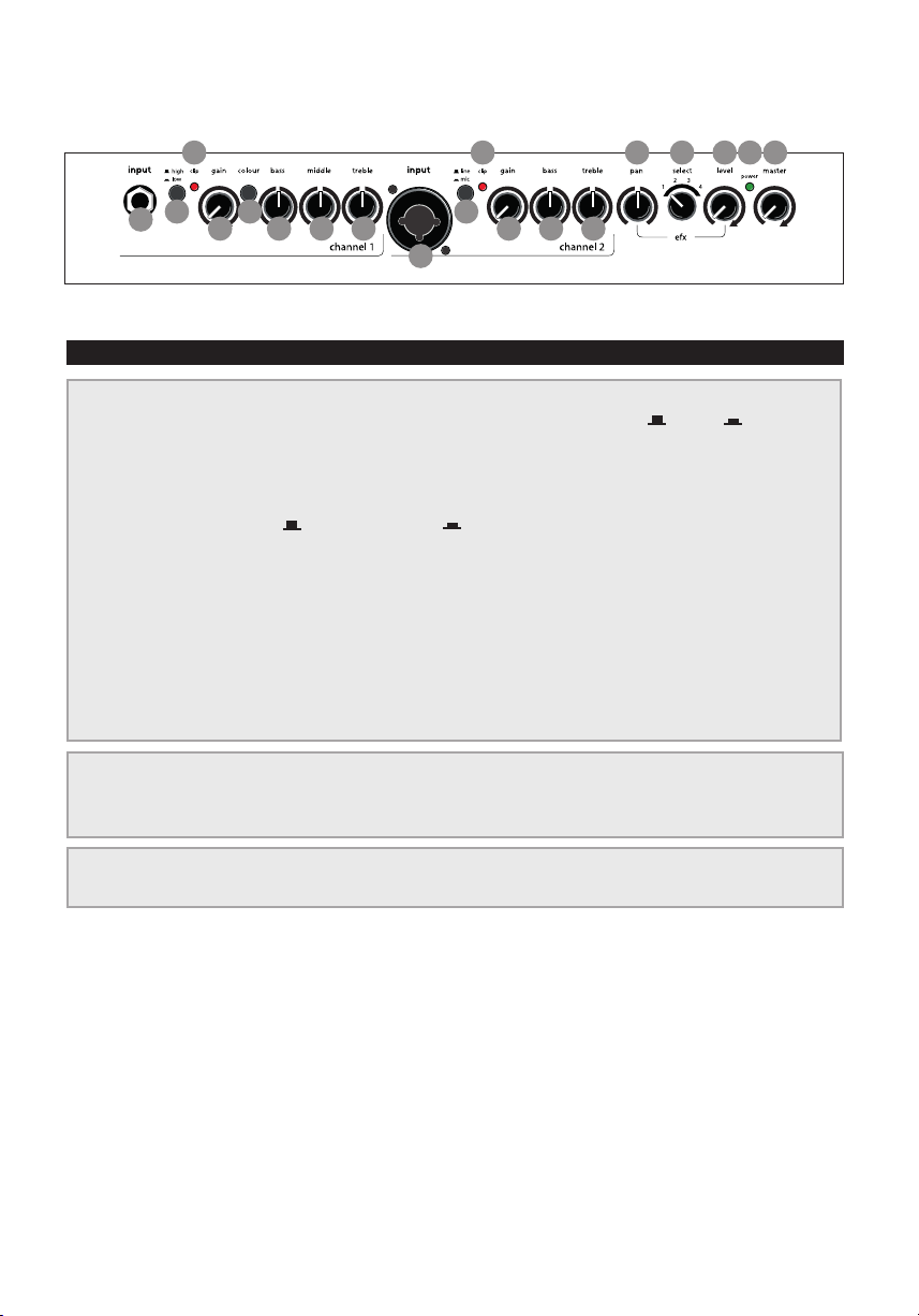
3. Contrôles et connexions
1
IF_Compact603_20120529
3 3
2
5
4 4
7
6 6
8 8
9
10
11 12 13 14 15
Compact 603
3.1 Face avant
1) input (ch. 1) Prise d‘entrée Jack mono.
2) high/low Commutateur de sensibilité d’entrée, atténuateur = o = on
3) clip Indicateur clip
4) gain Contrôle du gain
5) colour Outon pour ajuster la sensibilité d‘entrée
= haute sensibilité = basse sensibilité
6) bass Contrôle les fréquences graves
channel 1 + 2
7) middle Contrôle les fréquences médiums
8) treble Contrôle les fréquences aiguës
9) input (ch. 2) Entrée commutable avec mode ligne et mode micro Prise Combo,
XLR + prise ¼” (6,35 mm)
10) line/mic Bouton de sélection de la source de signal:
line: pour instrument (capteur) uniquement par la prise Jack.
mic: pour micro par la prise Jack ou XLR.
11) pan Contrôle de distribution de signal d'eet
12) selec t Commutateur de sélection d'eet
13) level Contrôle le niveau des eets internes
efx
14) power Ce voyant s‘allume lorsque l‘ampli est prêt à être utiliser
15) master master Contrôle le volume général
20
mains & master
Page 21
Compact 603
twin channel acoustic amplier
12345
line out
return
headphones
CA UT I O N
RISK OF ELECTRIC SHOCK
DO NOT OPEN
AT T E N T I O N
RISQUE DE CHOC ELECTRIQUE
NE PAS OUVRIR
send
tuner
6
footswitch
tip = int. efx
ring = ext. efx
on/o
power on
DI-out
1 = gnd
2 = pos
3 = neg
8
7
IB_Compact603_20120529
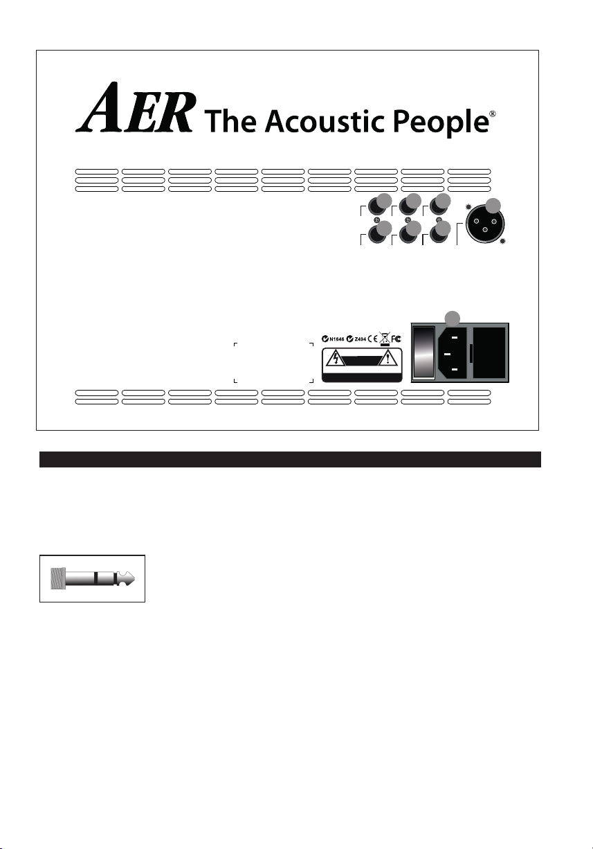
3.2 Face arrière
1) line out
Sortie préampli, après le volume général.
Jack mono 6,35 mm.
2) headphones
Sortie pour casque.m Jack stéréo 6,35 mm.
Note : Le casque doit avoir un
Jack stéréo. Ne pas brancher
de Jack mono.
3) send
Sortie vers l‘entrée des eets externes.
Jack mono 6,35 mm.
4) return
Entrée pour le retour des eets externes. Jack mono
6,35 mm.
5) tuner
Sortie vers un accordeur. Jack mono 6,35 mm.
Made in Germany by
B
6) footswitch
Prise pour double pédale pour commuter les eets
internes et externes. (pointe = eets internes,
anneau = eets externes).
Jack stéréo 6,35 mm.
7) DI-out
Sortie préampli symétrique XLR.
8) power on
Prise d‘alimentation avec porte-fusible et interrupteur
marche/arrêt
21
Page 22
4. Mise en service
colour bass middle treble
colour bass middle treble
4.1 Connexion et mise sous tension
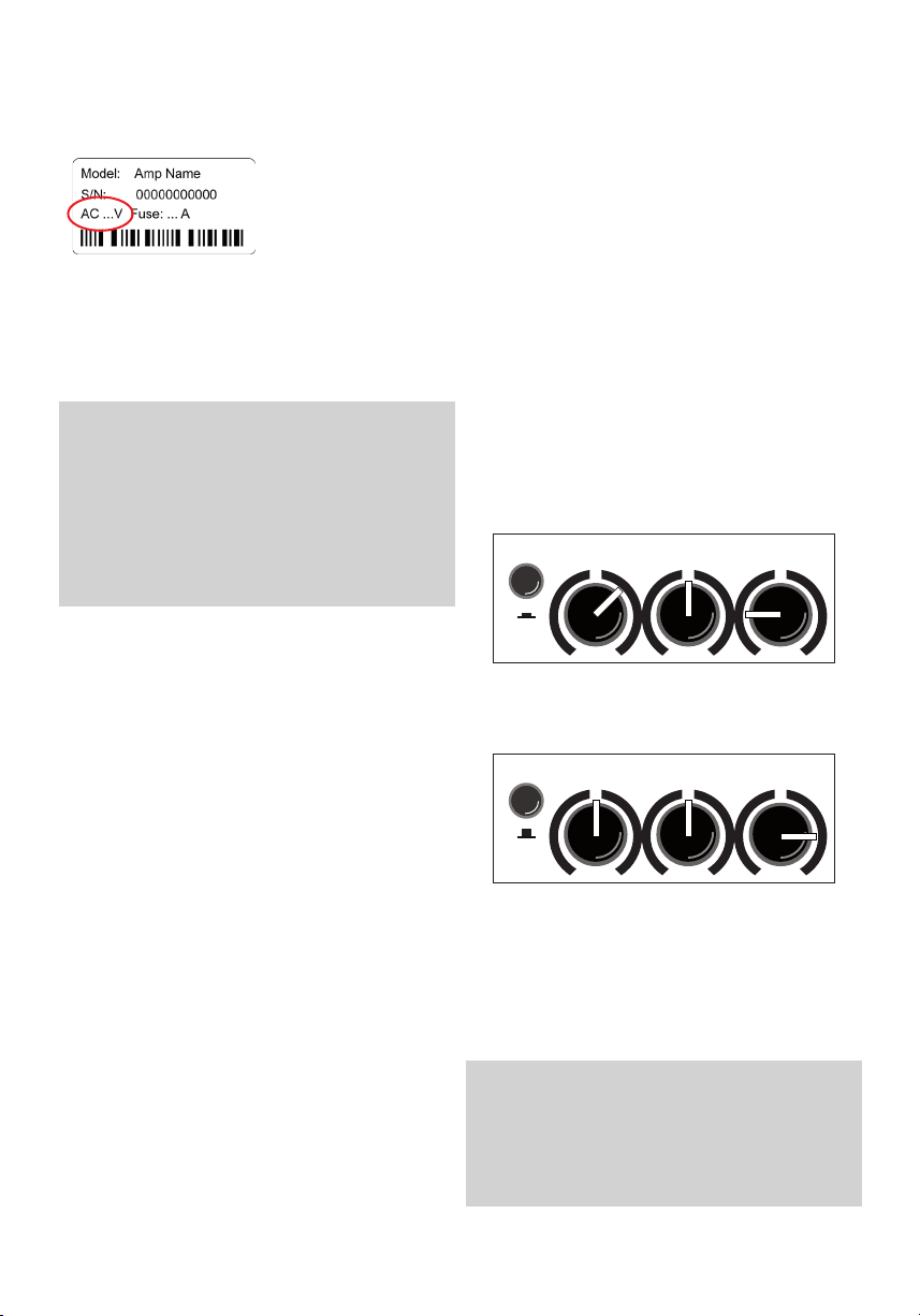
Vériez que le réseau local (par ex. 230 V en Europe,
120 V aux États-Unis)
correspond à la
tension du réseau
de l’appareil. Cela
est indiqué derrière
l’appareil. Eectuez
ensuite tous les raccordements de câbles voulus
et allumez l’appareil. Le voyant de contrôle vert
signie que l’appareil est prêt.
4.2 Level adjustment
Laissez d’abord le régulateur principal en position
zéro. Testez les haut-parleurs au niveau sonore le plus élevé. Augmentez progressivement
le réglage du GAIN, le plus possible, en faisant
attention au voyant Clip rouge. Il ne doit s’allumer
qu’exceptionnellement (au niveau le plus élevé).
Lorsque le réglage de GAIN correct a été trouvé,
déterminez le volume nal désiré avec le régulateur
principal.
• Les régulateurs de GAIN vous permettent
d’adapter diérents systèmes pick-up à
l’Compact 60
naux, an d’atteindre la meilleure performance
sonore possible.
• Si le réglage de GAIN est trop faible,
l’Compact Slope ne peut pas fonctionner
correctement. Le volume maximum ne peut
pas être atteint et le rapport signal/bruit se
détériore.
• Avec un gain transmetteur surviennent des
distorsions audibles. Grâce aux voyants-clips
vous êtes prévenu(e) rapidement.
• Si l’instrument possède un régulateur de
volume, essayez de régler celui-ci au volume
maximum. Si le voyant Cl 0p s’allume déjà
avec le réglage de GAIN le plus bas, revenez au
réglage précédent.
• Assurez-vous toujours que les piles de votre
Système PickUp sont complètement chargées.
Sinon, cela cause souvent des bourdonnements, des siements et des distorsions.
3, par exemple des sources de sig-
5. Description du fonctionnement
5.1 Réglages
L’égaliseur trois bandes de votre Compact Slope est
un dispositif de modication de la qualité sonore
actif et haut de gamme qui conserve le son naturel
des instruments et des voix an d’accentuer de
manière ciblée.
Dès la position médiane de tous les régulateurs, le
système électronique génère une sonorité agréable
et naturelle, que vous pouvez «colorer» avec le
ltre de couleurs: les centres y seront abaissés et les
hauteurs relevés (-3 dB à 700 Hz, +10 dB à 8 kHz).
Le son est alors plus ouvert, plus léger et convient
particulièrement aux techniques de cordes pincées.
L’égaliseur peut augmenter ou réduire l’eet des ltres de couleur et permet ainsi d’obtenir diérentes
tonalités médianes.
A: avec ltre de couleur (interrupteur pressé),
réduire les aigus et éventuellement réduire
l’acuité
B: sans ltre de couleur (interrupteur non pressé),
augmenter les aigus an d’ouvrir le son.
Remarque:
L’égaliseur actif de l’Compact Slope a une incidence sur la
modulation. Si vous remarquez que le témoin vert de la
LED Clip s’allume plus souvent, corrigez avec le régulateur
de Gain en conséquence (cf 4.2 Commande).
22
Page 23

5.2 Eets
Le Compact Slope dispose d’un processeur d’eet
intégré (interne) numérique. Avec son interrupteur
select vous pouvez choisir entre 4 eets diérents:
1 = réverbération 1 (courte)
2 = réverbération 2 (longue)
3 = délai (320 ms)
4 = chorus
Le régulateur de niveau FX détermine la part des
eets internes du signal d’origine choisis
(en butée gauche = aucun eet).
Par ailleurs, un processeur d’eets supplémentaire
(eet externe) peut être connecté au
Compact Slope. Veuillez utiliser la douille «send»
et «return» («send» pour l’intrant,
«return» pour l’extrant de l’eet ext.) située au dos
de l’appareil. Réglez le niveau d’eet intégré au
processeur d’eets. Grâce au potentiomètre PAN
FX vous pouvez mélanger les eets diérents des
canaux continus.
Ainsi :
Butée de gauche : eet interne sur le canal 1
eet externe sur le canal 2
Position centrale : eet interne sur le canal 1+ 2
eet externe sur le canal 1+2
Butée droite : eet interne sur le canal 2
eet externe sur le canal 1
5.3 Commutateur au pied
Sur la prise du pédalier sur la face arrière de
l’appareil, il est possible de connecter un pédalier
double standard (marche/arrêt) il avec un câble stéréo. Ce pédalier permet d’activer/désactiver l’eet
interne et l’eet externe..
5.4 Alimentation fantôme
Les micros qui nécessitent une alimentation fantôme de 48 V peuvent être directement connectés à
la prise XLR de l’entrée 1. L’alimentation fantôme est
activée à la livraison et peut, cependant, être désactivée au moyen d’un pont enchable interne.
Sur l’entrée 2, une alimentation de 9 V peut être
activée ultérieurement grâce à un pont enchable
interne.
Attention : pour les deux interventions mentionnées plus haut, l’appareil doit être ouvert, c’est
pourquoi ces modications de l’activation/désactivation de l’alimentation fantôme ne doivent être
eectuées que dans un atelier spécialisé.
Remarque sur l’utilisation
de l’alimentation fantôme
(Phantom-Power = alimentation à distance, ici :
alimentation d’un appareil par le câble audio).
Connectez uniquement des appareils aptes à
l’alimentation fantôme. Ces appareils portent
une marque spécique; vériez la consommation électrique autorisée (cf caractéristiques
techniques).
La plupart des microphones dynamiques équipés de transmission de signaux symétrique n’ont
certes pas besoin d’alimentation fantôme, mais
ils peuvent la supporter.
Sur les autres appareils qui n’ont pas été
conçus explicitement pour fonctionner avec
l’alimentation fantôme, des problèmes ou des
dommages majeurs peuvent survenir.
Par exemple :
Les micros dynamiques simples munis de jack
monos (transmission de signaux asymétrique)
qui ont été ultérieurement modiés avec une à
une che XLR.
Les appareils audio munis d’une sortie XLR symétrique (par ex. boîtes de direct, les processeurs
d’eets, les préamplicateur d’instrument avec
sortie directe, etc.) qui ne sont pas protégés contre l’alimentation fantôme sur leur sortie XLR.
Les autres appareils audio (comme les préamplicateurs, les pédales d’eet, etc), dont la sortie
Line asymétrique a été modiée par une che
XLR.
En cas de doute, veuillez vous renseigner auprès
du fabricant de l’appareil que vous utilisez.
Nous vous souhaitons bien du plaisir avec votre Compact Slope!
23
Page 24

6. Donnée techniques
canal 1 Entrée de la ligne / de l’instrument, haute
impédance, prise jack mono déséquilibrée,
1⁄4“ (6,35 mm) Tension d’entrée
nom. : 100 mV (–20 dBV)
Bouton haut/ bas (atténuateur) :
–10 dB Min.de tension d’entrée :
haute : 22 mV (–33 dBV)
basse : 68 mV (–23 dBV)
Tension d’entrée max. ( THD = 1%) :
haute : 3,5 V (+11 dBV)
basse : 5 V (+14 dBV)
Impédance d’entrée : 2,2 M || 350 pF
Signal / rapport sonore (Décibel A): 95 dB
Tension sonore d’entrée équivalente
(Décibel A) : 1,8 V (– 115 dBV)
Alimentation sonore : optionnelle (voir notes),
9 V DC / 100 mA max., bague de la prise
d’entrée, protection contre les courts-circuits.
clip Indicateur Marge : min. 6 dB
canal 2 canal d’entrée commutable avec un mode
ligne et une prise combo mode microphone,
XLR + prise 1⁄4” (6,35 mm)
Mode ligne / mode instrument
(prise d’entrée uniquement)
haute impédance, tension d’entrée Nom.
Déséquilibrée : 100 mV (–20 dBV)
Tension d’entrée min. : 27 mV (–31 dBV )
Tension d’entrée max. : 7 V (+17 dBV)
Impédance d’entrée : 2.2 M || 350 pFSignal /
ratio sonore (Décibel A) : 92 dB
Tension sonore d’entrée équivalente (Décibel
A) : 2,7 (– 111 dBV)
Mode Entrée microphone XLR (symétrique),
prise stéréo ou prise mono (asymétrique) 1 /
manchon = terre,v2 / pointe = pôle positif (+),
3 / bague = pôle négatif (-)
Tension d’entrée nominale : 10 mV(–40 dBV )
tension d’entrée min : 3,3 mV (–50 dBV)avec
l’option : 5,8 mV (–45 dBV)
(cf notes)tension d’entrée max.: 1 V (0 dBV)
avec option : 1,6 V (+4 dBV)
Impédance d’entrée (équilibrée) :
1,2 k Impédance d’entrée
(déséquilibrée) : 2,7 k
Filtre de bruit :–10 dB at 270 Hz réferré 10 kHz
rapport signal/bruit (Décibel A) : 80 dB Tension
sonore d’entrée équivalente (Décibel A) :
1 V (–120 dBV)Alimentation fantôme: 48 V,
XLR seulement, R = 6,8 k per terminal, 10 mA
total max., protection contre les court-circuits
(cf notes).
clip Indicateur Marge : 6 dB
retour Retour (entrée) de boucle d’eet parallèle
externe, ou entrée supplémentaire
Prise Mono, ¼” (6,35 mm)
Tension d’entrée nominale : 320 mV (–10 dBV )
Impédance d’entrée : 5 V (+14 dBV) Input
impedance: 20 k
ligne externe Sortie du préamplicateur après mastérisation,
contrôles de tonalité et prise Mono d’eets, ¼”
(6,35 mm)
Tension de sortie nominale : 700 mV (–3 dBV)
Impédance de sortie : 100
Min. Impédance de charge : 2 k
Bruit résiduel (pondéré en A) :
4.5 V (–107 dBV)
Casque Tension de sortie nominale sans charge :
15.5 V (+24 dBV)
Impédance de sortie (par canal): 40
Impédance de charge : 8...2000
Puissance de sortie nominale
(THD < 1%): 2 x 2 mW / 8
2 x 50 mW / 2000 Residual noise
(A-weighted): 2.7 V (–111 dBV) / 8
220 V (–73 dBV) / 2000
Remarque : pour casque avec prise stéréo
(TRS) seulement.
Ne fonctionne pas avec les prises mono.
Envoi Envoyer (sortie) pour retour d’eet, avant la
mastérisation et les contrôles de tonalité, prise
Mono, ¼ “ (6,35 mm)
Tension de sortie : 47
Min. load impedance: 2 k
Impédance de sortie : 47
Impédance de charge : 2k
Turner Sortie du turner
Prise Mono, ¼” (6,35 mm)
Tension de sortie min : 145 mV (-17 dBV)
Impédance de sortie : 47
Impédance de charge min : 2k
Pédalier Connecteur pour prise stéréo pédalier double,
¼” (6,35 mm)
pointe = eet interne marche/arrêt
bague = eet externe marche/arrêt
manchon = commun (terre)
Fonction: interrupteur MARCHE = eet ARRÊT
Contrôles des tonalités
canal 1 color -3 dB/700 Hz
basses +10dB / 8kHz
moyennes ± 8dB at 100 Hz, commutable
aigus ± 6dB at 800Hz
canal 2 basses ± 8 dB at 100 Hz, commutable
aigus ± 11dB at 10 kHz, commutable
Eets
Eet interne Réverbération numérique intégrée
Eet externe Boucle d’eet parallèle, cf envoyer et retour.
Amplicateur de puissance
Construction Circuit intégré monolithique avec sortie DMOS
Puissance
de sortie 60 W / 4 W (THD = 1%)
L’alimentation de circuit continue est déterminée par un limiteur, cf seuil du limiteur.
Générale
Distortion THD + N < 0.1% (6 W / 4 W),
Évaluée aux terminaux d’enceinte
24
Page 25

6. Donnée techniques
Bruit Bruit résiduel (NPA-au niveau pondéré en
A) : env. 17 dB (A) / 1 m
Voir aussi entrées et sorties pour
spectomètres de bruit
Traitement de signaux analogique
Filtre anti-résonnance,
limiteur de pointe adaptatif
Limiter threshold50 W / 4 ohms
Système d’enceinte
Enceinte complète double cône 8“
(200 mm), , caisson reex de graves
bass reex enclosure
Alimentation électrique
Tension secteur (selon le modèle): 100, 120,
230, ou 240 V, 50-60 Hz Puissance absorbée :
max. 100 W
Mains fuse Size: 5 x 20 mm
For 230 and 240 V models: T 1A L 250V
For 100 and 120 V models: T 2A L 250V
Plage de température de fonctionnement
0…35 °C
Coret électrique
12 mm (0.47”) birch plywood
Peinture Acrylique à l’eau, nition noire type
éclaboussures rbased acrylic, black spatter
nish
Dimensions and weight
Dimensions 259 mm (10.19“) de haut
311 mm (13.04“) de large
137/235 mm (5.39"/12.84“) de profondeur
Poids 7,2 kg (15.87 lbs)
Notes
Options congurable by internal jumpers (refer
modication to qualied personnel):
· 9 V phantom power for channel 1.
Caution: Phantom power may damage external
equipment. Read the notes in the operating
instructions.
· Low-gain option (more headroom) for mic input
· Deactivation of 48V phantom power for mic input
DEFINITIONS
Rated conditions
· Nominal input voltage at input under test
· master fully clockwise
· high / low and colour o
· bass / middle / treble / pan centered
· gain of unused inputs and efx level fully anticlockwise
· gain of input under test adjusted to nominal output
voltage at line out. (This condition corresponds by design
to the rated output power.)
Nominal input voltage: Standard condition for specications,
if not stated otherwise.
Minimum input voltage: Input voltage required for nominal
output with maximum gain and volume settings.
Maximum input voltage: Input voltage that does not cause
distortion more than rated THD+N, suitable control settings
provided.
Nominal output voltage or power refers to rated conditions.
THD + N: Total harmonic distortion + noise, input
voltage reduced by 10 dB after setting up rated
conditions.
Signal / noise ratio: Ratio of output voltage at rated
conditions to output noise voltage with input shorted.
Equivalent input noise voltage: Noise voltage at loudspeaker
terminals divided by gain of amplier. Input shorted after
setting up rated conditions.
Residual noise: Output noise with minimal gain and volume
settings.
Adaptive limiter: Adaptive with respect to power supply.
Maintains constant headroom regardless of power supply
uctuations.
General: Signal voltages are RMS values. Test signal sine 1 kHz
sine unless stated otherwise. Noise measured from 20 Hz to
20 kHz. Noise stated for a specic input implies that all other
inputs are not used. Sound pressure level (SPL) based on loudspeaker specication by manufacturer.
Specications and appearance subject to change without
notice.
TD20160511 (Compact Slope)
25
Page 26
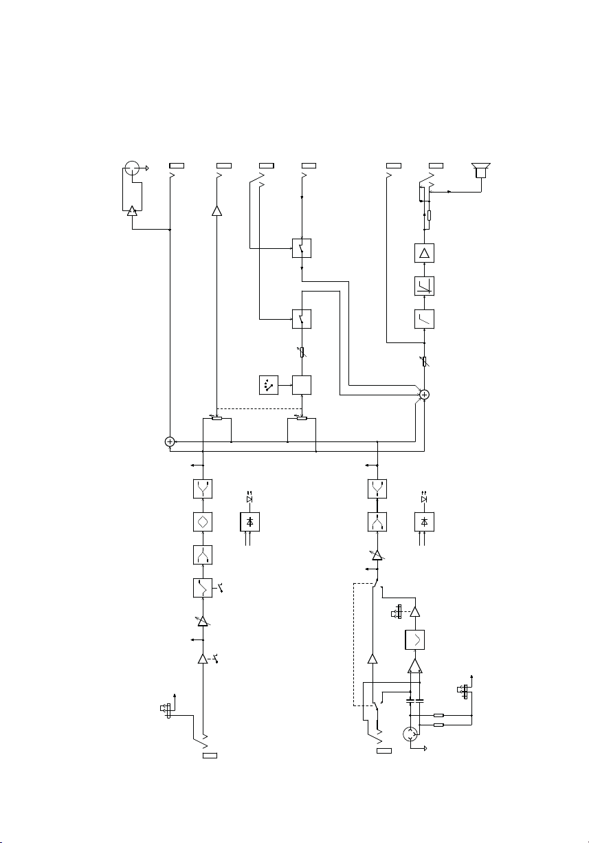
7. Blockschaltbild/Circuit diagram/ Schéma fonctionnel
B090216E_20160921
DI-out
2
3
TUNER
1
SEND
FOOTSWITC H
RE TURN
T R
LINE OUT
HEADPHONES
T R
DUAL CONE SP EAKER
470R
POWER AMP
SUBS ONIC LIMITER
EFX / LE VEL
EFX / SE LEC T
EFX / PAN
CLIP DETE CTION
TRE BLEBASS
CLIP
CLIP DE TECTION C H. 1
DIGITAL EFF ECTS
CW CW
CLIP DETE CTION
BASS TR EBLE
MASTER
. 2
CLIP
CLIP DE TECTION C H
26
GAIN
CLIP DETE CTION
COLOUR
COLOUR MIDDLE
CLIP DETE CTION
LINE
GAIN
CLIP DETE CTION
HIGH / LOW
PRE AMP
+9V
PRE AMP
LINE
9V Phantom Power
TR
CH1
CLIP DETE CTION
MIC
MIC GAIN H/L
VOICE
PRE AMP
MIC
2
TR
3
1
+48V
48V Phantom Power
6k8
6k8
CH2
Page 27

27
Page 28

Sales
Europe
Sales
Africa, America, Asia, Oceania
28
aer music gmbh
Haberstrasse 46
D-42551 Velbert
AER The Acoustic People GmbH
Bredenscheider Str. 119b
D-45527 Hattingen
www.aer-music.de
 Loading...