

Page 1

user manual
Alpha
Register your
Alpha:
www.aer-amps.com
> product registration
1
Page 2

Alpha
user manual
Contents Page
1. Introduction 3
2. Important safety instructions 4
3. Controls and connections 5
3.1 Front side 5
3.2 Rear side 6
4. Starting up 7
4.1 Cabling and switching-on 7
4.2 Level adjustment 7
5. Functional characteristics 7
5.1 Tone control 7
5.2 Effects 8
5.3 Footswitch 8
5.4 Phantom powering 8
6. Technical specications 9
7. Circuit diagram 10
2
Page 3

1. Introduction
Welcome to B!
Thank you for choosing the Alpha.
The Alpha
amplier system. Especially developed for the enhancement of acoustic instruments, it is as well suitable
for other (also electrical) instruments.
With one channel but two independant input stages
(line and microphone/line) the Alpha offers you various options in signal processing.
40 Watts plus the 8“-twin-cone speaker-system of the
Alpha provide you with a well-balanced tone at all
sound pressure levels.
All AER-systems are subtly dynamically controlled,
which ensures absolute reliability in full load operation despite strikingly small sizes and little weight.
Read on and have fun using your Alpha!
is a professional, compact and powerful
3
Page 4

2. Important Safety Instructions
The following guidelines shall help minimize the risk of injury through re or electric shock.
CAUTION
RISK OF ELECTRIC SHOCK
DO NOT OPEN
ATTENTION
RISQUE DE CHOC ELECTRIQUE
NE PAS OUVRIR
The lightning ash with
the arrow head symbol
within an equilateral triangle is intended to alert the user
to the presence of unisolated
´dangerous voltage´ within this
product´s enclosure that may be
of sucient magnitude to constitute a risk of electric shock to
persons.
1. Carefully read these safety notes before you use
the device!
2. Keep these safety notes in a safe place.
3. Pay attention to all warnings, instructions and ad-
ditional texts on the unit.
4. This device was only designed for operation under
normal climatic conditions (temperate climate).
5. Do not install or use your amp in close proximity
to water or if you are wet yourself.
6. Do not subject your device to sudden and severe
temperature changes. This could cause moisture
condensation inside the unit, which could damage
it. In the event of moisture condensation allow the
device to dry out completely before use.
7. Use your amp in a safe place where nobody can
step on cables or trip over and damage them.
8. Pay attention to an unhindered air circulation
around the amp, never obstruct the air vents or grilles.
9. Always pull the mains plug before cleaning your
amp or when left unused for a long period of time.
Use only a dry cloth for cleaning. Avoid the use of detergents and do not let any liquids seep into the unit.
10. Use only the right fuses with the same current
rating and trigger characteristic as replacements.
Never mend fuses! Pull the mains plug before replacing a fuse. Should a fuse blow again after a short
while, the device needs to be checked.
11. Never install your amp close to devices with
strong electromagnetic elds such as large mains
transformers, revolving machines, neon illumination
etc. Do not lay signal cables parallel to power current
cables.
12. There are no user-serviceable components inside the unit. To avoid the risk of an electric shock,
the unit must not be opened. All maintenance, adjustment and repair works should be carried out by
The exclamation point
within an equilateral
triangle is intended to
alert the user to the presence of
important operating and maintenance (servicing) instructions in
the literature accompanying this
product.
qualied sta only. Any unauthorized tampering will
void the 2-year warranty.
13. In keeping with the EMV regulations screened
cables with correctly tted connectors must be used
for all signal connections.
14. Always use an earthed power supply with the
correct mains voltage. If you are in doubt about the
power outlet ground, have it checked by a qualied
technician.
15. Cable up your amp only when it is powered o.
16. This device should be installed near the socket
outlet and disconnection of the device should
be easily accessible. The mains plug of the power
supply shall remain readily operable. Protect the power cord from being walked on or pinched particularly at plugs, convenience receptacles and the point
where they exit from the apparatus.
17. This product may cause permanent hearing loss.
Do not operate for long periods of time at a high
volume level or at any level that is uncomfortable.
If you experience any hearing loss or ringing in the
ears, you should consult an audiologist.
18. The product should be located away from heat
sources such as radiators, heat registers or other products that produce heat.
19. Do not place any open sources of re, like candles, on the device.
20. Care should be taken so that objects do not fall
onto the device and liquids are not spilled into the
enclosure through openings. Ensure that no objects
lled with liquids, such as vases, are placed on the
device.
21. Do not place this device on an unstable
cart, stand, tripod, bracket or table. The device may fall, causing serious injury to you
and serious damage to the device itself.
4
Page 5
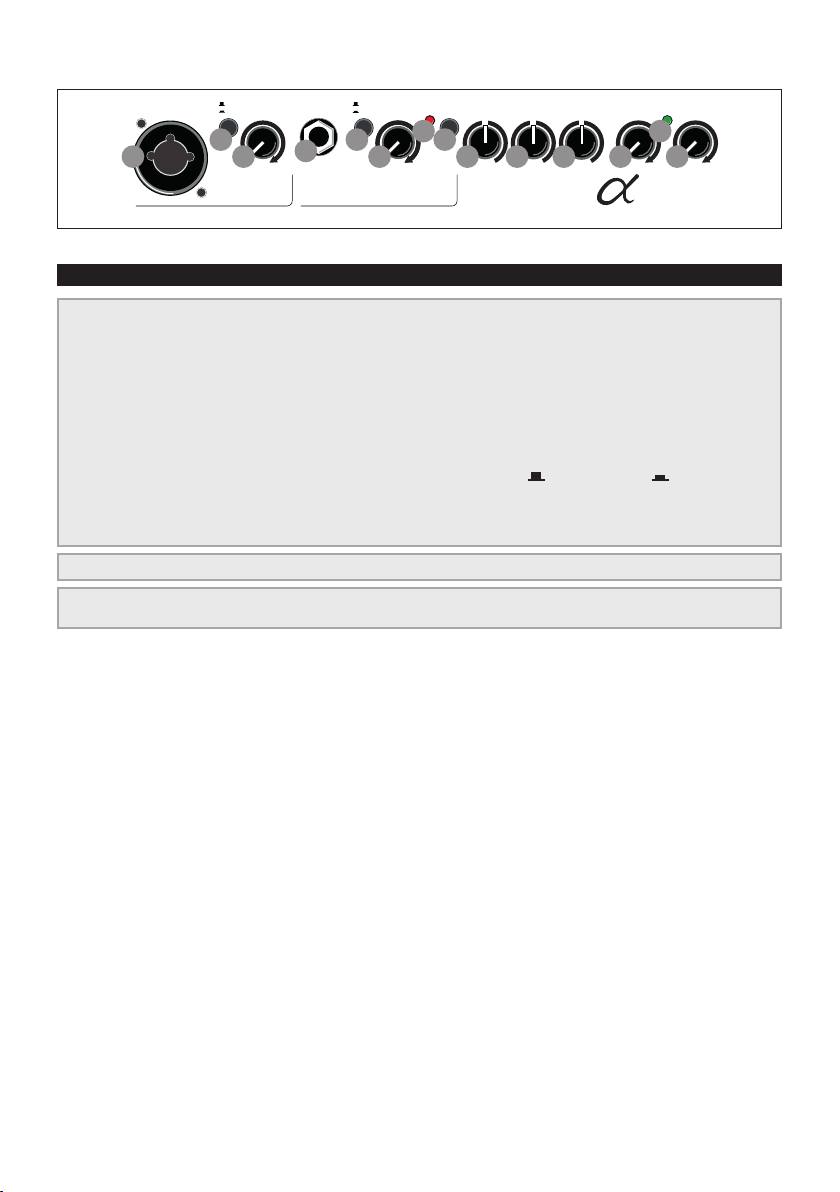
3. Controls and connections
input gain input
1
line
mic
2
3
high
gain
low
5
4
3
colour
bass middle treble efx level
clip
6
7
8
9
master
power
12
10
13
11
alpha
IF_Alpha_20110621
input 1
input 2
3.1 Front side
1) input (inp. 1) signal input, combo-socket for 6,3 mm mono jackplug and
XLR-connectors (48V phantom power)
2) line/mic signal source selector switch: line (only via jackplug)
for instruments (pickup) and other line level sources,
mic (only via XLR-connector) for microphones
3) gain input level control
4) input (inp. 2) signal input, socket for 6,3 mm mono jackplug
5) high/low input sensitivity switch, attenuator
6) clip overload indicator
7) colour tone colour lter activation switch = not active = active
8) bass bass frequency level control
9) middle middle frequency level control
10) treble treble frequency level control
inputs 1 + 2
11) efx level effect level control (reverb)
12) power on/off status indicator
13) master master level control
mains & master
efx
5
Page 6
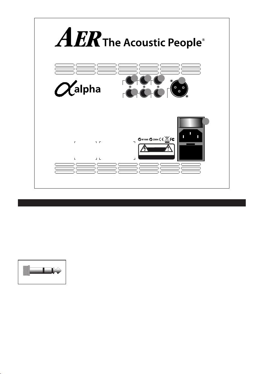
line out
headphones
12345
send
tuner
footswitch
return
tip = int. efx
ring = ext. efx
on / off
CAUTION
RISK OF ELECTRIC SHOCK
DO NOT OPEN
ATT ENTI ON
RISQUE DE CHOC ELECTRIQUE
NE PAS OUVRIR
7
6
DI-out
1 = gnd
2 = pos
3 = neg
power on
8
Made in Germany by
IB_Alpha_20110621
3.2 Rear side
1) line out
The line out supplies a pre-amp signal taken after
tone-control, effects and master for forwarding to
other appliances.
2) headphones
This output enables you to connect stereo headphones and mutes the loudspeaker.
Warning: Only use
!!!
headphones with stereo
jackplugs in this output
socket!!!
3) send
Send is an output to connect to an external effect
device and in conjunction with return (input) forms
a loop here designed as external effect loop. The effect can be switched on or off via footswitch.
4) return
Return as part of the effect loop operates as signal
input from an external effect device (from output
B
of the effect device). The effect can be switched on
or off via footswitch. Return on its own can also be
used as quasi auxiliary signal input (-10 dbV).
5) tuner
The tuner output supplies a pre-master signal (-9
dbV) to connect an external tuner to the Alpha.
6) footswitch
Connection socket for a double-footswitch (on-/off-
switch, tip = internal effect/ring = external effect on/
off).
7) DI-out
Preamp-output with symmetrical signal, after tonecontrol, pre master, without effects.
8) power on
Combined mains switch with mains socket and fuse
holder.
6
Page 7
4. Starting up
colour bass middle treble
colour bass middle treble
power
master
clip
colour
high
low
input
gain
bass middle treble efx level
alpha
input 2
power
master
bass middle treble efx level
alpha
4.1 Cabling and switching on
Before connecting to mains, please ensure that your
local mains voltage is suitable for the voltage of the
device (e.g. 120V in the
USA, 230V in Europe).
The relevant specs and
safety symbols are printed on the rear side of
the unit.
Connect all cables ac-
cording to your application and switch the amplier
on. The green power control LED indicates operational readiness.
4.2 Level adjustment
Note: Level adjustment
By setting the level correctly we mean the signal level in
one or several devices in a signal chain is neither too high
nor too low. This applies equally to all circuits in a complete
circuit design (EQs, preamps etc.)
Consequently, care must be taken that no part of the circuit
is overloaded or that distortion is unintentionally added to
the signal.
We have carefully designed the circuit to achieve this objective whilst also providing controls for „manual“ intervention.
The clip-LED indicates an overload. A short icker
is of no danger to AER devices. During operation a
short icker can be accepted, to be on the safe side
you should reduce the gain slightly to achieve an optimal and distortion-free performance.
Finally set the desired overall volume level with the
master level control.
5. Functional characteristics
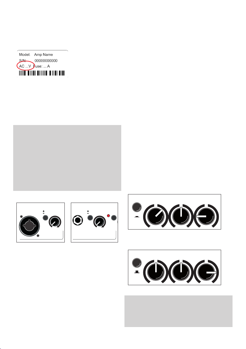
5.1 Tone control
The triple-band equalizer of your Alpha provides
you with an active and high quality sound interaction tool that supports the natural tone of instruments and voice whilst simultaneously offering you
the possibility of a controlled accentuation.
With all controls in mid position the lters are set to
produce a very pleasing and natural sound impression that you can „colour up“ by using the colour l-
ter with the effect of lowering the mids and lifting
the trebles. The tone becomes more open and light
and is especially suited for ngerpicking techniques.
The equalization can support or soften the effect of
the colour lter and allows a differentiated mids-
accentuation.
A: with colour-filter (switch pressed)
reduce treble to soften possible sharpness
input gain
line
mic
input 1
input
First ensure, that the master level control is zeroed
(over to far left), so that when you are setting the
sound level, the signal passes through the electronics only and does not reach the loudspeaker. By
pressing the high-/low- (attn.) resp. line-/mic-swit-
ches you can adapt the amplier to your signal sources (guitar pickups, microphone etc).
Turn the gain control clockwise until the red clip
indicator ashes momentarily when playing with a
strong attack. Thus you make sure that your signal
source (e.g. instrument) provides the input-stage of
the amplier with the necessary input.
high
low
colour
gain
clip
input 2
B: without colour-filter (switch not pressed)
boost treble to brighten the sound
Note:
The active equalization of the Alpha effects the sig-
nal adjustment. If you spot an intensied ickering
of the clip indicator, readjust the signal level with
the gain control (s. 4.2 Level adjustment).
7
Page 8

5.2 Effects
The Alpha has a built-in (internal) reverb-effect. The
efx-level-control determines the intensity of the in-
ternal effects (left stop = no effect).
Furthermore an additional effects unit (external effect) may be connected to the Alpha. For this purpose use the send and return sockets on the rear side
of the amplier (send goes to input, return to the
output of the external effects device). The intensity
of the effect is adjusted at the external effects unit.
The external effect loop works „parallel“, the effect
is blended with the original signal.
5.3 Footswitch
A standard double-footswitch (on-/off-switch) can be
plugged into the footswitch-socket on the rear side
of the amplier via stereo cable. By this footswitch
the internal and external effects can be switched on
and off.
5.4 Phantom power
Microphones requiring 48V phantom power can
be directly connected to the XLR-socket of input 1.
Factory-provided phantom power is activated but, if
required, may be deactivated by an internal jumper.
In contrary 9V phantom power, if required, can
additionally be activated in input 2 by an internal
jumper.
Please note: For both alterations the device must be
opened, therefore only qualified service personnel
may carry out the modifications concerning the de-/
activating of phantom power.
General Note: Use of 48V or 24V phantom power
(Phantom power = remote supply, here: powering
an audio device via the connected audio line)
Turn on the phantom power only if the unit connected to an XLR socket that is designed to handle it!
In general, suitable units are e.g. condenser microphones, active DI-boxes and other special audio
devices, whose power supply is drawn from the
phantom power. Such devices are also labelled accordingly; please heed the permissible power consumption (max.10mA).
High-quality dynamic microphones with a balanced
signal need no phantom power, but can handle it
anyway.
Other devices, which have not been designed explicitly for phantom power operation, can suffer from
considerable malfunctions and damage may result as
well.
Examples of devices that may be damaged by incorrect application of phantom power include:
Low-cost dynamic microphones with a mono jack-
plug (unbalanced signal) that were tted afterwards
with an XLR connector.
Audio devices with a balanced XLR output (e.g. DIboxes, effects devices, instrument preamps with a DI
output etc.) which are not protected against phantom power applied to their XLR output. (The DI connectors on AER products are protected against applied phantom power.)
Other audio devices (such as preamps, effects pedals
etc.) whose unbalanced line output was replaced by
an XLR socket.
If in doubt please consult the manufacturer of the
device you are using.
We wish you lots of fun playing your Alpha!
P.S.: For questions or suggestions contact us:
8
Page 9
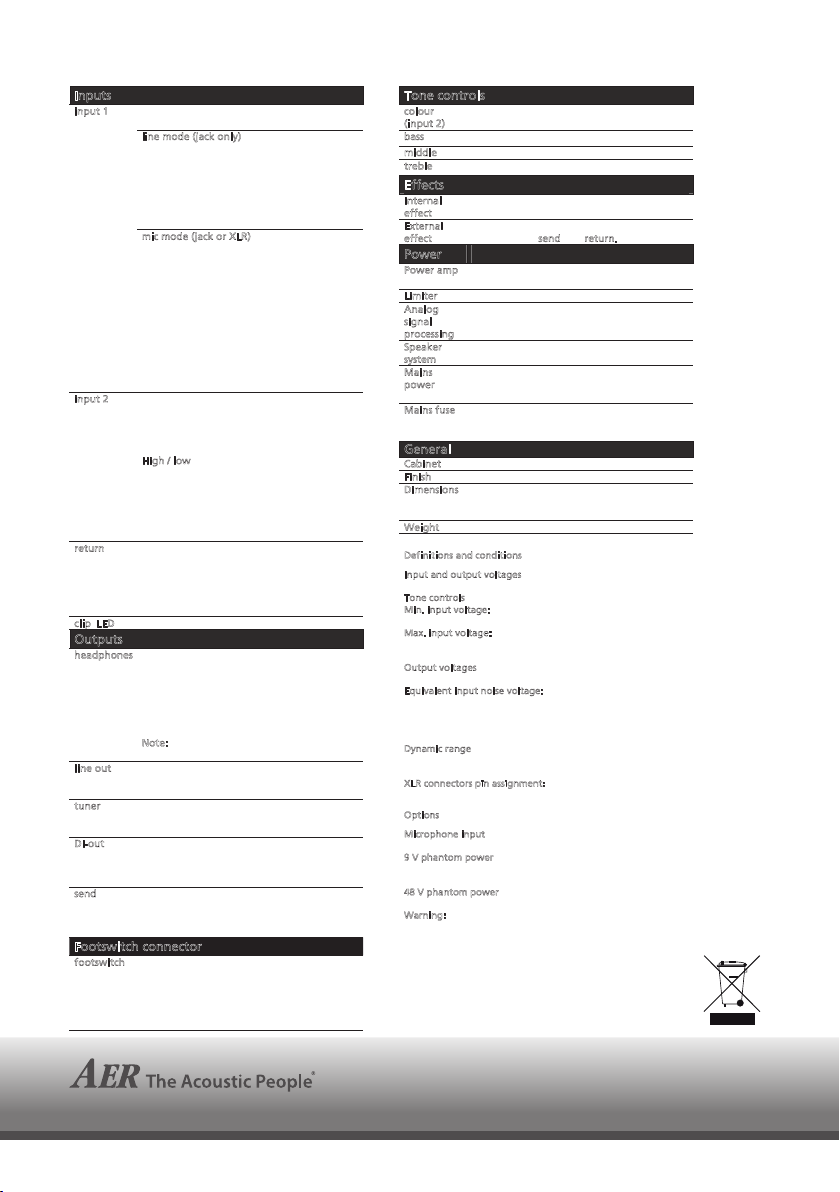
6. Technical specications Alpha
Technical data
Inputs
input 1
input 2 Unbalanced high-impedance input for
return Return input for effect loop
clip LED Headroom: min. 8 dB
Outputs
headphones Headphones output. When plugged in, the
line out Preamplifier output after master volume
tuner Tuner output
DI-out Balanced XLR output before master, after
send Send output for effect loop, before master,
Footswitch connector
footswitch Connector for a dual footswitch
Switchable line or microphone input
Combo socket, XLR + jack ¼” (6.35 mm)
line mode (jack only)
Unbalanced high-impedance input for
instrument pick-ups and line-level sources
Min. input voltage: 16 mV (–36 dBV)
Max. input voltage: 7 V (+17 dBV)
Input impedance: 2 M || 300 pF
Equivalent input noise, A-weighted:
2.1 μV (–114 dBV)
m
ic mode (jack or XLR)
XLR (balanced), stereo jack (balanced), or
mono jack (unbalanced) microphone input
Min. input voltage: 2 mV (–54 dBV)
Max. input voltage: 1 V (0 dBV)
Input impedance (balanced): 1.2 k
Input impedance (unbalanced): 2.7 k
Voice filter: –10 dB at 260 Hz (ref. to 10 kHz)
Equivalent input noise, A-weighted:
0.7 μV (–123 dBV)
Phantom power: 48 V (XLR only), R = 6.8 k
per terminal, total current max. 10 mA,
short circuit protected.
instrument pick-ups and line-level sources
Mono jack, ¼” (6.35 mm)
Min. input voltage: 14 mV (–37 dBV)
Max. input voltage: 5 V (+14 dBV)
H
igh / low switch: attenuator –10 dB
Input impedance: 2.2 M || 300 pF
Equivalent input noise, A-weighted:
1.2 μV (–118 dBV)
Optional phantom power (see notes): 9 V DC
at “ring” terminal, max. 100 mA, short
circuit protected
Mono jack, ¼” (6.35 mm)
Min. input voltage: 150 mV (–17 dBV)
Max. input voltage 5 V (+14 dBV)
Input impedance: 20 k (5 k if effect is
switched off by footswitch.)
internal speaker is switched off.
Stereo jack, ¼” (6.35 mm), L / R connected
Max. output power: 2 x 65 mW / 1000
Input sensitivity for 2 x 50 mW / 1000 :
19 mV (–35 dBV) at input 1, line mode
Output impedance: 470 (shared by L and R)
N
ote: Suitable for headphones with stereo
jack. Does not work with mono jacks.
Mono jack, ¼” (6.35 mm)
Output voltage: 1.4 V (+3 dBV)
Mono jack, ¼” (6.35 mm)
Output voltage: 450 mV (–7 dBV)
tone controls, without effects
Output voltage (differential):
190 mV (–15 dBV)
after tone controls
Mono jack, ¼” (6.35 mm)
Output voltage: 450 mV (–7 dBV)
Stereo jack, ¼” (6.35 mm)
tip = internal effect on/off
ring = external effect on/off
sleeve = common (ground)
Effect is OFF when the footswitch is ON.
Tone controls
colour
(
input 2)
bass
middle
treble
Effects
Internal
e
ffect
External
e
ffect
Power
Power amp
Limiter
Analog
s
ignal
p
rocessing
Speaker
s
ystem
Mains
p
ower
Mains fuse Size: 5 x 20 mm
General
Cabinet 12 mm (0.47”) birch plywood
Finish Waterbased acrylic, black spatter finish
Dimensions 260 mm (10.24“) high
Weight 6.2 kg (13.7 lbs)
Definitions and conditions
I
nput and output voltages are RMS values for a sine signal and
T
one controls in neutral position unless stated otherwise.
M
M
O
utput voltages refer to 50 mV (–26 dBV) at input 1, line mode,
E
quivalent input noise voltage: Noise voltage at speaker
D
ynamic range of power amplifier: Ratio of output voltage at
X
LR connectors pin assignment:
O
ptions
M
9
V phantom power for input 2 can be activated by an internal
4
8 V phantom power for the XLR input can be deactivated by
W
Specifications and appearance subject to change without
–3 dB at 700 Hz, +10 dB at 8 kHz, switchable
8 dB at 100 Hz, shelf type
6 dB at 800 Hz
8 dB at 10 kHz, shelf type
Built-in digital reverb
Parallel effect loop (effect blended with dry
sound), see send and return.
40 W / 4 at 1% THD, DMOS, monolithic I.C.
Dynamic range, A-weighted: 92 dB
Threshold 35 W / 4
Subsonic filter, adaptive peak limiter
8” (200 mm) twin cone full-range speaker,
bass reflex enclosure
Mains voltage (depending on model):
100, 120, 230, or 240 V~, 50–60 Hz.
Power consumption: max. 100 W
For 230 and 240 V models: T 1 A L
For 100 and 120 V models: T 2 A L
265 mm (10.43“) wide
235 mm (9.25“) deep
1 kHz unless stated otherwise.
in. input voltage: Required input voltage for 35 W / 4
output, gain and master fully clockwise.
ax. input voltage: Allowable input voltage that does not
cause more than 1% total harmonic distortion, assuming
suitable control settings.
gain and master max.
divided by voltage gain of amplifier for white noise, for the
input under test. Gain and master fully clockwise, input
shorted, 20 Hz – 20 kHz, gain of unused inputs in zero
position.
limiter threshold to A-weighted noise voltage with master in
zero position.
1 = ground, 2 = positive (+), 3 = negative (–)
icrophone input can be attenuated by 5 dB by an internal
jumper, increasing the max. input voltage to 1.6 V (+4 dBV).
jumper. When activated, operation without phantom power
is still possible by using a mono jack connector.
an internal jumper. (The jack input does not have 48 V.)
arning: External equipment may be damaged by
inappropriate use of phantom power.
notice.
TD20111206
www.aer-amps.com
Alpha_121128_GB
9
Page 10
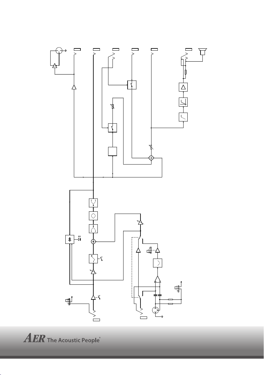
7. Circuit diagram Alpha
TUNER
DI
1
2
3
SEND
TREBLEBASS
MIDDLE
F/S
T R
EFFECT
FX
RETURN
LINE
MASTER
GAIN 1
PHONES
T R
470R
POWER AMP
SUBSONIC LIMITER
B090217B_20110912
DUAL CONE SPEAKER
www.aer-amps.com
Alpha_121128_GB
10
CLIP
MIC
CLIP DETECT
OFF/ON
COLOUR
GAIN 2
+9V
PREAMP
HIGH/LOW
TR
9V PHANTOM POWER
INPUT 2
LINE
PREAMP
MIC GAIN H/L
VOICE
PREAMP
MIC
LINE
2
TR
3
1
INPUT 1
+48V
48V PHANTOM POWER
6.8k
6.8k
Page 11

notes
11
Page 12

www.aer-amps.com
Alpha_121128_GB
12
 Loading...