


User Manual
WITH AEMC® INSTRUMENTS
Class
A
POWERP
POWERP
ENGLISH
PowerPad® IV
Model 8345
POWER QUALITY ANALYZER
D IV
D IV

Copyright © Chauvin Arnoux®, Inc. d.b.a. AEMC® Instruments. All rights reserved.
No part of this documentation may be reproduced in any form or by any means (including electronic
storage and retrieval or translation into any other language) without prior agreement and written consent
from Chauvin Arnoux
Chauvin Arnoux
®
, Inc., as governed by United States and International copyright laws.
®
, Inc. d.b.a. AEMC® Instruments
15 Faraday Drive • Dover, NH 03820 USA
Tel: (800) 945-2362 or (603) 749-6434 • Fax: (603) 742-2346
This documentation is provided “as is,” without warranty of any kind, express, implied, or otherwise.
Chauvin Arnoux
®
, Inc. has made every reasonable eort to ensure that this documentation is accurate;
but does not warrant the accuracy or completeness of the text, graphics, or other information contained
in this documentation. Chauvin Arnoux®, Inc. shall not be liable for any damages, special, indirect,
incidental, or inconsequential; including (but not limited to) physical, emotional or monetary damages
due to lost revenues or lost prots that may result from the use of this documentation, whether or not the
user of the documentation has been advised of the possibility of such damages.

Statement of Compliance
Chauvin Arnoux®, Inc. d.b.a. AEMC® Instruments
certifies that this instrument has been calibrated using
standards and instruments traceable to international
standards.
We guarantee that at the time of shipping your
instrument has met its published specifications.
An NIST traceable certificate may be requested at
the time of purchase, or obtained by returning the
instrument to our repair and calibration facility, for
a nominal charge.
The recommended calibration interval for this
instrument is 12 months and begins on the date of
receipt by the customer. For recalibration, please
use our calibration services. Refer to our repair and
calibration section at www.aemc.com.
Serial #:
Catalog #: 2136.35 / 2136.36
Model #: 8345
Please fill in the appropriate date as indicated:
Date Received:
Date Calibration Due:
Chauvin Arnoux®, Inc.
d.b.a AEMC® Instruments
www.aemc.com

TABLE OF CONTENTS
1. INTRODUCTION ................................................................................ 1
1.1 PRECAUTIONS FOR USE ........................................................ 2
1.2 RECEIVING YOUR SHIPMENT ................................................ 2
1.3 ORDERING INFORMATION ..................................................... 3
1.3.1 Accessories .................................................................................... 3
1.3.2 Replacement Parts ........................................................................3
1.5 CHARGING THE BATTERY ...................................................... 4
1.6 CHOOSING A LANGUAGE FOR THE DISPLAY .................... 4
2. PRODUCT FEATURES ..................................................................... 5
2.1 DESCRIPTION ........................................................................... 5
2.1.1 Recording Functions.......................................................................5
2.1.2 Display Functions ........................................................................... 6
2.1.3 Measurement Functions ................................................................ 7
2.1.4 Conguration Functions .................................................................7
2.2 OVERALL VIEW ........................................................................ 8
2.3 MEASUREMENT TERMINALS ................................................ 9
2.4 SIDE CONNECTORS ................................................................ 9
2.5 BATTERY .................................................................................. 10
2.6 DISPLAY UNIT ......................................................................... 10
2.7 ON/OFF BUTTON .................................................................... 10
2.8 KEYPAD .................................................................................... 11
2.8.1 Mode Buttons (Purple Buttons) ....................................................11
2.8.2 Navigation Buttons ......................................................................11
2.8.3 The Other Buttons ....................................................................... 12
2.8.4 The Function Buttons (8 Yellow Buttons) ...................................12
2.9 INSTALLING THE COLOR CODES ....................................... 12
2.10 MEMORY CARD ..................................................................... 13
2.11 P R OP ....................................................................................... 14
2.12 MAGNETIZED HOOK (OPTIONAL) ...................................... 14
3. CONFIGURATION ........................................................................... 15
3.1 NAVIGATION ............................................................................ 15
3.2 USERS ...................................................................................... 15
3.3 CONFIGURING THE INSTRUMENT ..................................... 17
3.3.1 Language .....................................................................................17
3.3.2 Date and Time .............................................................................17
3.3.3 Display .........................................................................................19
3.3.4 Memory ........................................................................................ 19

3.3.5 Network........................................................................................21
3.3.6 Updating the Embedded Software ..............................................23
3.3.7 Information ...................................................................................24
3.4 CONFIGURING THE MEASUREMENT................................. 24
3.4.1 Calculation Methods ....................................................................25
3.4.2 The Distribution Network and the Type of Connection ...............28
3.4.3 Sensors and Ratios .....................................................................33
3.4.4 Trend Mode ..................................................................................34
3.4.5 Transient Mode ............................................................................36
3.4.6 Inrush Current Mode ....................................................................37
3.4.7 Alarm Mode .................................................................................38
3.4.8 Energy Mode ...............................................................................39
3.4.9 Monitoring Mode ..........................................................................40
3.4.10 Flagging......................................................................................40
4. OP ER ATION ..................................................................................... 41
4.1 TURNING THE INSTRUMENT ON ......................................... 41
4.2 NAVIGATION ............................................................................ 41
4.2.2 Touch Screen............................................................................... 41
4.2.3 Remote User Interface ................................................................ 41
4.3 CONFIGURATION ................................................................... 43
4.4 CONNECTIONS ....................................................................... 43
4.4.1 Single-Phase Network ................................................................. 43
4.4.2 Split-Phase Network ....................................................................43
4.4.3 Three-Phase Network .................................................................44
4.4.4 Connection Procedure .................................................................44
4.5 INSTRUMENT FUNCTIONS ................................................... 45
4.5.1 Measurements .............................................................................45
4.5.2 Screenshot...................................................................................45
4.5.3 Help..............................................................................................46
4.6 TURNING THE INSTRUMENT OFF ...................................... 46
4.7 SA FET Y STATU S ..................................................................... 46
5. WAVEFORM ..................................................................................... 47
5.1 D I SP L AY F I LT E R...................................................................... 47
5.2 ROOT MEAN SQUARE (RMS) FUNCTION ........................... 48
5.3 TOTAL HARMONIC DISTORTION (THD) FUNCTION ......... 49
5.4 CREST FACTOR (CF) FUNCTION ......................................... 49
5.5 MIN-MAX FUNCTION ............................................................. 50
5.6 SUMMARY FUNCTION ........................................................... 51
5.7 PHASOR FUNCTION .............................................................. 53

6. HARMONICS .................................................................................... 55
6.1 D I SP L AY F I LT E R...................................................................... 56
6.2 EXAMPLES OF SCREENS ..................................................... 57
7. P O WE R .............................................................................................. 59
7.1 D IS PL AY FI LT ER ...................................................................... 59
7.2 EXAMPLES OF SCREENS ..................................................... 59
8. ENERGY ............................................................................................ 61
8.1 D I SP LAY F I LT E R...................................................................... 61
8.2 EXAMPLES OF SCREENS ..................................................... 62
9. TREND MODE .................................................................................. 63
9.1 STARTING A RECORDING ..................................................... 63
9.2 THE LIST OF RECORDINGS ................................................. 64
9.3 READING A RECORDING ...................................................... 65
10. TRANSIENT MODE .......................................................................68
10.1 STARTING A RECORDING ................................................... 68
10.2 THE LIST OF RECORDINGS ............................................... 69
10.3 READING A RECORDING .................................................... 70
11. INRUSH CURRENT MODE ........................................................... 73
11.1 STARTING A CAPTURE ........................................................ 73
11.2 THE LIST OF CAPTURES ..................................................... 74
11.3 READING A CAPTURE ......................................................... 74
11.3.1 RMS Values ................................................................................75
11.3.2 Instantaneous Values.................................................................76
12. ALARM MODE ...............................................................................78
12.1 PROGRAMMING AN ALARM RECORDING ....................... 78
12.2 THE LIST OF ALARM RECORDINGS ................................. 79
12.3 STARTING AN ALARM RECORDING ................................. 80
13. MONITORING MODE .................................................................... 81
13.1 STARTING A MONITORING RECORDING ......................... 81
13.2 THE LIST OF MONITORING RECORDINGS...................... 83
13.3 READING A MONITORING RECORDING .......................... 84
14. SCREENSHOTS ............................................................................. 85
14.1 TAKING A SCREENSHOT ..................................................... 85
14.2 MANAGING THE SCREENSHOTS ...................................... 85
14.2.1 Displaying a Screenshot ............................................................86
15. HELP ............................................................................................... 87
16. APPLICATION SOFTWARE .........................................................88
16.1 OBTAINING THE SOFTWARE .............................................88

17. TECHNICAL SPECIFICATIONS ................................................... 89
17.1 REFERENCE CONDITIONS ................................................. 89
17.2 ELECTRICAL SPECIFICATIONS..........................................92
17.2.1 Input Voltage Specications .......................................................92
17.2.2 Current Input Specications .......................................................92
17.2.3 Bandwidth and Sampling ...........................................................92
17.2.4 Instrument Specications (Without Current Sensors) ...............94
17.2.5 Specications of the Current Sensors .................................... 104
17.2.6 Uncertainty of the Real-Time Clock .........................................105
17.3 MEMORY CARD ................................................................... 105
17.4 POWER SUPPLY .................................................................. 106
17.4.1 Battery ..................................................................................... 106
17.4.2 External Power Supply .............................................................107
17.4.3 Battery Life ...............................................................................107
17.5 DISPLAY CONDITIONS....................................................... 108
17.6 ENVIRONMENTAL CONDITIONS ...................................... 108
17.7 MECHANICAL SPECIFICATIONS ...................................... 109
17.8 COMPLIANCE WITH INTERNATIONAL STANDARDS .... 109
17.8.1 Electrical Safety ....................................................................... 109
17.8.2 Standard IEC 61000- 4-30, Class A ......................................... 110
17.8.3 Measurement Uncertainties and Ranges ................................ 110
17.8.4 Markings per IEC 62586-1 ....................................................... 112
17.9 ELECTROMAGNETIC COMPATIBILITY (EMC) .................112
17.10 RADIO EMISSIONS ............................................................112
17.11 G P L C O D E ............................................................................112
18. MAINTENANCE ............................................................................113
18.2 SENSOR MAINTENANCE ...................................................113
18.3 BATTERY REPLACEMENT .................................................113
18.4 MEMORY CARD ...................................................................115
18.5 UPDATING THE FIRMWARE ..............................................115
18.6 REPAIR AND CALIBRATION...............................................116
18.7 TECHNICAL ASSISTANCE ..................................................116
18.8 LIMITED WARRANTY ..........................................................117
18.8.1 Warranty Repairs ..................................................................... 117
20.1 N O TATI O N .............................................................................118
20.2 FORMULAS ...........................................................................119
20.2.1 RMS Values .............................................................................119
20.2.2 Peak Values .............................................................................119
20.2.3 Crest Factor ............................................................................. 119

20.2.4 Levels of Harmonics and Interharmonics ................................ 119
20.2.5 Level of Unbalances ................................................................120
20.2.6 Mains Signaling Voltages (MSV) .............................................120
20.2.7 Level of Harmonic Group Distortion ........................................121
20.2.8 Distortion .................................................................................121
20.2.9 K Factor and Harmonic Loss Factor ........................................121
20.2.10 Frequency ..............................................................................122
20.2.11 DC Component ......................................................................122
20.2.12 Active Power (P) .....................................................................122
20.2.13 Fundamental Active Power (Pf) .............................................122
20.2.14 Fundamental Reactive Power (Qf) .........................................123
20.2.15 Harmonic Active Power (PH) ..................................................123
20.2.16 DC Power (PDC) ......................................................................123
20.2.17 Apparent Power (S) ................................................................123
20.2.18 Non-Active Power (N) ............................................................124
20.2.19 Distorting Power (D) ...............................................................124
20.2.20 Power Factor (PF), Power Factor of Fundamental (PF1) ......124
20.2.21 Tangent ..................................................................................125
20.3 FLICKER ............................................................................... 125
20.4 SOURCES OF DISTRIBUTION SUPPORTED BY THE
INSTRUMENT .............................................................................. 126
20.5 HYSTERESIS ....................................................................... 126
20.5.1 Voltage Swell Detection ...........................................................126
20.5.2 Voltage Dip and Voltage Interruption Detection ...................... 126
20.6 MINIMUM SCALE VALUES OF WAVEFORMS AND
MINIMUM RMS VALUES............................................................. 127
20.7 FOUR-QUADRANT DIAGRAM ........................................... 127
20.8 TRANSIENT CAPTURE TRIGGERING MECHANISM .... 128
20.9 CONDITIONS OF CAPTURE IN INRUSH CURRENT
MODE ............................................................................................ 128
20.10 GLOSSARY ......................................................................... 129
20.11 UNIT PREFIXES ................................................................. 134

1. INTRODUCTION
Thank you for purchasing an AEMC® Instruments PowerPad® IV Model 8345.
For best results from your instrument and for your safety, read the enclosed
operating instructions carefully and comply with the precautions for use.
Only qualied and trained operators should use this product.
Symbols
CAUTION - Risk of Danger! Indicates a WARNING. Whenever this symbol
is present, the operator must refer to the user manual before operating the
instrument in all cases where this symbol is present
Indicates a risk of electric shock. The voltage at the parts marked with this
symbol may be dangerous
USB socket
Kensington anti-theft lock
Ethernet connector (RJ45)
Ground/Earth
Indicates important information to acknowledge
SD card
This product has been declared recyclable following an analysis of the life
cycle in accordance with standard ISO 14040
This product complies with the Low Voltage & Electromagnetic Compatibility
European directives (73/23/CEE & 89/336/CEE)
In the European Union, this product is subject to a separate collection system
for recycling electrical and electronic components in accordance with directive
WEEE 2002/96/EC
Denition of Measurement Categories (CAT)
CAT IV corresponds to measurements at the source of low-voltage installations.
Example: power feeders, counters, and protection devices.
CAT III corresponds to measurements on building installations.
Example: distribution panel, circuit-breakers, machines, and xed industrial devices.
CAT II corresponds to measurements on circuits directly connected to
low-voltage installations.
Example: power supply to domestic electrical devices and portable tools.
Power Quality Analyzer PowerPad® IV Model 8345 1

1.1 PRECAUTIONS FOR USE
This instrument complies with safety standard IEC/EN 61010-2-030 or BS EN
61010-2-030. The leads comply with IEC/EN 61010-031 or BS EN 61010-031.
The current sensors comply with IEC/EN 61010-2-032 or BS EN 61010-2-032
for up to 600 V in CAT IV.
Failure to observe the precautions for use may create a risk of electric shock,
re, explosion, or destruction of the instrument and installations.
■
Only competent and accredited personnel may perform troubleshooting or
metrological checks
■
The operator and responsible authority must read and understand the
various precautions to take before and during use
■
The operator must have knowledge and awareness of electrical hazards
when using this instrument
Do not use the instrument in an unspecied manner; otherwise, the
protection that the instrument provides may become compromised and
endanger you
Do not use the instrument on networks that exceed the instrument’s
specications for voltage or category
Do not use the instrument if it seems to be damaged, incomplete, or
improperly closed
Do not use the instrument without its battery
Before each use, check the condition of the insulation on the leads,
housing, and accessories. Any item with deteriorated insulation (even
partially) must be set aside for repair or scrapping
Ensure that your instrument is completely dry before use. If it is wet, you
must dry it completely before connecting or using it
Use only the supplied leads and accessories. If you use any leads or
accessories with lower voltage or category ratings, you are limited to lowest
voltage or category rating
Use personal protection equipment when appropriate
Keep your hands away from the instrument’s terminals
Keep your ngers behind the physical guards when handling the leads, test
probes, and alligator clips
Use only the manufacturer-provided power supply unit and battery pack
because these items have specic safety components
At hazardous voltages, certain current sensors must not be placed on or
removed from bare conductors. Please refer to each sensor’s data sheet
and comply with their handling instructions
1.2 RECEIVING YOUR SHIPMENT
Upon receiving your shipment, make sure that the contents are consistent with
the packing list. Notify your distributor of any missing items. If the equipment
appears to be damaged, le a claim immediately with the carrier and notify your
distributor at once with a detailed description of any damage. Save the damaged
packing container to substantiate your claim.
2 Power Quality Analyzer PowerPad® IV Model 8345

1.3 ORDERING INFORMATION
PowerPad® IV Model 8345 (No Probes) .......................................Cat. #213 6. 35
Includes meter, extra-large tool bag, internal carrying pouch, hand strap, USB
cable, ve 10 ft black voltage leads with alligator clips, twelve color-coded input
ID markers, power adapter (PA32ER) with US power cord, two 6 ft stackable
leads, two 10 ft black voltage leads with alligator clips for power adapter
PA32ER, SD Card, one power plug adaptor for PA32ER, 5.8 A·h Li-ion battery
pack, quick start guide, and USB stick with DataView® software and user manual.
PowerPad
®
IV Model 8345 (w/4 MA194-24-BK Sensors) ............ Cat. #2136.36
Includes meter, extra-large tool bag, internal carrying pouch, hand strap, four
MA194-24-BK sensors, USB cable, ve 10 ft black voltage leads with alligator
clips, twelve color-coded input ID markers, power adapter (PA32ER) with US
power cord, two 6 ft stackable leads, two 10 ft black voltage leads with alligator
clips for power adapter PA32ER, SD Card, one power plug adaptor for PA32ER,
5.8 A·h Li-ion battery pack, quick start guide, and USB stick with DataView®
software and user manual.
1.3.1 Accessories
AC/DC Current Probe Model MR193-BK .........................................Cat. #214 0. 28
AC Current Probe Model MN93-BK ................................................. Cat. #2140.32
AC Current Probe Model SR193-BK................................................Cat . # 2140.33
AmpFlex
AmpFlex
AC Current Probe Model MN193-BK ............................................... Cat . # 2140.36
MiniFlex
MiniFlex
Magnetic Hook for use with PowerPad
®
Model 193-24-BK ............................................................ Cat. #2140. 34
®
Model 193-36-BK ........................................................... Cat. #2140.35
®
Sensor Model MA193-10-BK ........................................... Cat. #2140.4 8
®
Sensor Model MA193-14-BK ........................................... Cat. #2140.50
®
IV Model 8345 ................. Cat. #5100.16
1.3.2 Replacement Parts
Carrying Bag .................................................................................... Cat. #2133.76
Lead - Set of 5, 10 ft (3M) Black Leads
w/5 Black Alligator Clips ...................................................................Cat. #2140.43
Lead - One 10 ft (3M) Black Lead w/1 Black Alligator Clip ..............Cat. #2140.44
Cable - Replacement 5 ft USB Cable ..............................................Cat. #2140.46
Sensor - MiniFlex
Battery-5.8 AH 64 WH Li-ion Battery Pack .....................................Cat. #2960.47
Adapter - Replacement Power Plug Adapter for PA32ER ............... C at. #5100.14
Adapter - Replacement 1000 V PA32ER
Power Supply for Model 8345 .......................................................... Ca t . # 51 00.15
Power Quality Analyzer PowerPad® IV Model 8345 3
®
Sensor Model MA194-24-BK ............................Cat. #2140.80
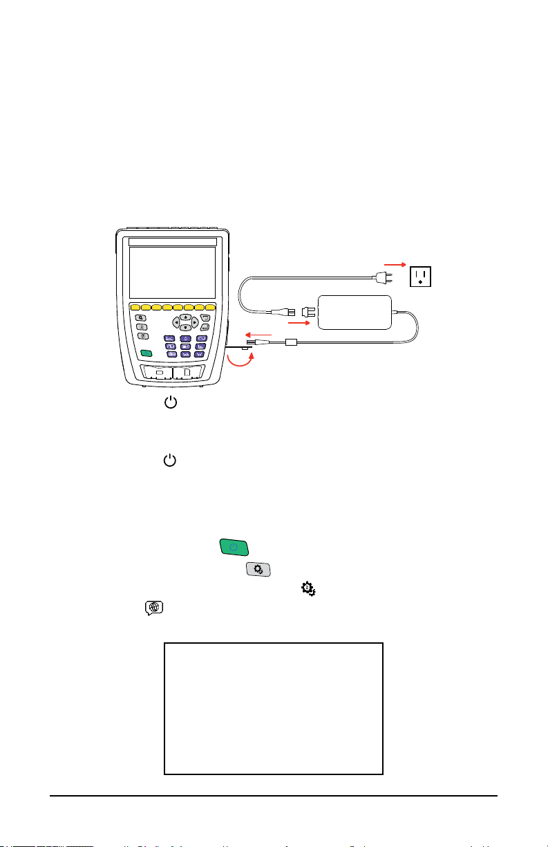
1.5 CHARGING THE BATTERY
Before using the instrument, you must fully charge the battery.
1. Remove the plastic lm preventing the connection between the battery and
instrument. To do this, refer to § 18.3, which explains how to remove the
battery from the instrument.
2. Connect the power cord to the power supply unit.
3. Plug the power cord into an outlet.
4. Open the elastomer cover that protects the power socket.
5. Connect the power supply’s 4-point connector to the instrument.
120 V ± 15 %, 60 Hz
230 V ± 15 %, 50 Hz
The ON/OFF button
the charging status.
When the battery is fully depleted, the charging time is approximately 6 hours.
The ON/OFF button
will blink while charging, and the display unit will indicate
will glow steady green when the battery is fully charged.
1.6 CHOOSING A LANGUAGE FOR THE D I SPL AY
You must choose a language for the display before using the instrument. The
8345 has more than 20 languages available to choose from.
1. Press the ON/OFF button
2. Press the conguration button
3. Press the second yellow function button
4. Then, press
5. Choose your desired language from the list that appears.
to open the language menu.
to turn the instrument on.
.
.
4 Power Quality Analyzer PowerPad® IV Model 8345

2. PRODUCT FEATURES
2.1 DESCRIPTION
The PowerPad® IV Model 8345 is a portable, three-phase power quality
analyzer that complies with the standards governing the methods of power
quality measurement, IEC 61000-4-30, Class A.
The 8345 can be used to:
■
Measure RMS values, powers, and disturbances of power distribution
networks
■
Take snapshots of the main specications of three-phase networks
■
Track variations of dierent parameters over time
The Model 8345 has a wide array of features that include the following:
■
Less than 0.1 % uncertainty for voltage measurements and less than 1 %
uncertainty for current measurements
■
Large selection of current sensors for measurements that range from a few
milliamperes to several kiloamperes
■
Built-in rechargeable battery
■
Compact and impact-resistant housing
■
Large, color, touch-screen graphic display unit
■
Up to three user proles
■
SD card for storing a large quantity of measurements and photographs that
can be read directly on a PC. You can also use a USB drive (optional)
■
Communication via USB, Wi-Fi, or Ethernet
■
Remote control from a PC, tablet, or smartphone via the remote user
interface (VNC)
■
Application software for processing recorded data and generating reports
2.1.1 Recording Functions
The 8345 has recording functions for various measurements and calculations:
■
RMS values of AC voltages up to 1000 V between terminals. Using ratios,
the instrument can reach hundreds of gigavolts
■
RMS values of AC currents up to 10,000 A (neutral included). Using ratios,
the instrument can reach hundreds of kiloamperes
■
Detection of current sensor types and powering of the sensor, if necessary
■
DC component of voltages and currents (neutral included)
■
RMS voltage and current over minimum and maximum half-cycles
(neutral excluded)
■
Direct, inverse, and zero sequence voltages and current unbalance
■
Inrush current for motor start-up applications
■
Peak values of voltages and currents (neutral included)
■
50 Hz and 60 Hz network frequency
Power Quality Analyzer PowerPad® IV Model 8345 5

■
Current and voltage crest factors (neutral included)
■
Harmonic loss factor (FHL) for application to transformers in the presence
of harmonic currents
■
K factor (FK) for application to transformers in the presence of harmonic
currents
■
40 alarms per user prole
■
Log of events, such as voltage dips, voltage swells, interruptions, transients,
rapid voltage changes (RVC), and synchronization
■
Total harmonic distortion of currents and voltages (neutral excluded)
referred to the fundamental (THD in %f)
■
Total harmonic distortion of currents and voltages (neutral included) referred
to the AC RMS value (THD in %r)
■
Active, reactive (capacitive and inductive), non-active, distorting, and
apparent power, per phase and total (neutral excluded)
■
Power factor (PF) and displacement factor (DPF or cos φ) (neutral excluded)
■
Distorting RMS value (d) for currents and voltages (neutral excluded)
■
Short-term icker of voltages (Pst) (neutral excluded)
■
Long-term icker of voltages (Plt) (neutral excluded)
■
Active, reactive (capacitive and inductive), non-active distorting, and
apparent energy, per phase and total (neutral excluded)
■
Energy valuation (€, $, £, etc.) with a basic rate and 8 special rates
■
Current and voltage harmonics (neutral included) up to order 63: RMS
value, percentages referred to the fundamental (%f) (neutral excluded) or to
the total RMS value (%r), minimum and maximum, and harmonic
sequence level
■
Apparent harmonic power (neutral excluded) up to order 63: percentages
referred to the fundamental apparent power (%f) or to the total apparent
power (%r), minimum and maximum of one order level
■
Current and voltage interharmonics up to order 62 (neutral included)
■
Synchronization with UTC with a choice of time zone
■
Monitoring mode to check the compliance of the voltages
■
Information signals on the CPL (MSV)
2.1.2 Display Functions
The 8345 has functions to display the following:
■
Waveforms for voltages and currents
■
Bargraphs of voltage and current harmonics
■
Screenshots
■
Instrument information, such as the serial number, software version, MAC,
Ethernet, USB, Wi-Fi addresses, and more
■
Recordings for trends, alarms, transients, and inrush currents
6 Power Quality Analyzer PowerPad® IV Model 8345

2.1.3 Measurement Functions
The trend recording (data logging) function oers the following features.
■
Time-stamping
■
Programming the recording’s beginning and end
■
Representation, in barcharts or curves, of mean values for many
parameters as a function of time, with or without the MIN-MAX
■
4 congurations per user prole
The transients function oers the following features.
■
Transient detection and recording for a chosen duration and on a chosen
date (the number of transients is limited by the SD card's size)
■
Programming of the transient recording’s beginning and end
■
Recording of 4 complete cycles in the 8 acquisition channels (one recording
before the transient-triggering event and three after)
■
Possibility of capturing shock waves up to 12 kV over a duration of 1 ms
The alarm function oers the following features.
■
A list of alarms recorded as a function of the thresholds programmed in the
conguration menu (up to 20,000 alarms)
■
Programming the session’s beginning and end
■
40 alarms per user prole
The inrush current function displays the following useful parameters for studying
motor start-up.
■
Instantaneous values of the current and voltage at the cursor's position
■
Absolute maximum instantaneous current and voltage over the starting event
■
Half-cycle RMS current and voltage (neutral excluded) at the
cursor’s location
■
Maximum half-cycle RMS current and voltage (over the starting event)
■
Instantaneous network frequency at the cursor's position
■
Maximum, mean, and minimum instantaneous network frequency over the
entire starting event
■
Time of motor start-up
2.1.4 Conguration Functions
The 8345 has conguration functions used to:
■
Set the date and time
■
Adjust the brightness
■
Choose the colors of the curves
■
Manage the screen’s auto-o
■
Choose the night mode display
■
Choose the language
■
Choose the calculation methods: whether non-active quantities are
Power Quality Analyzer PowerPad® IV Model 8345 7

broken down, the unit of energy, the K factor calculation’s coecients, the
N
L1
L2 L3
N
L1
L2 L3
reference for levels of harmonics, and the calculation of PLT (sliding window
or not)
■
Choose the distribution system: single-phase, two-phase, or three-phase
with or without neutral
■
Choose the connection method: standard, 2 elements, or 2½ elements
■
Congure the recordings, alarms, inrush currents, and transients
■
Erase the data (total or partial)
■
Display the current sensors: detected, not detected, not managed,
simulated, or impossible to simulate (2-element connection method)
■
Adjust the voltage and current ratios, transduction ratios, and sensitivity
■
Congure the communication links (Wi-Fi, Ethernet)
2.2 OVERALL VIEW
Measurement terminals
Touch screen
Function buttons
(Yellow buttons)
Conguration button
Return button
Screenshot button
Navigation buttons
Help button
Conrm button
ON/OFF button
Mode buttons
(Violet buttons)
USB port
SD card slot
8 Power Quality Analyzer PowerPad® IV Model 8345
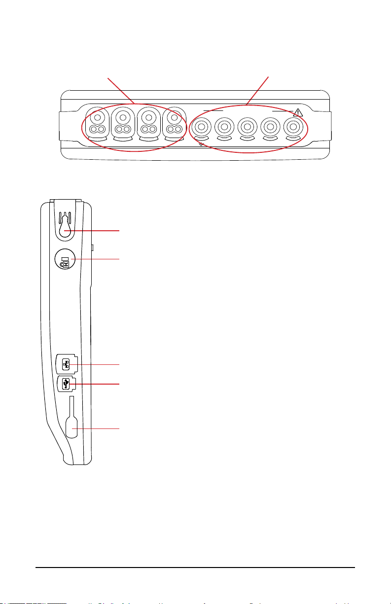
2.3 MEASUREMENT TERMINALS
1000V CAT IV
L2L1N
L3
L2L1N
L3
GND
4 current input terminals
(for current sensors)
2.4 SIDE CONNECTORS
Strap attachment point
Theft-proong device for securing the instrument with a
Kensington lock
5 voltage input terminals
RJ45 connector for Ethernet connection
USB type B connector for connection to a PC
Special 4-point connector for the power supply. Used to charge
the battery or operate the instrument on external power
Power Quality Analyzer PowerPad® IV Model 8345 9
2.5 BAT T E RY
The instrument can operate on battery power or wall power. While the battery
charges, the instrument can operate on wall power. The battery contributes to
the operator’s safety, so do not use the instrument without its battery.
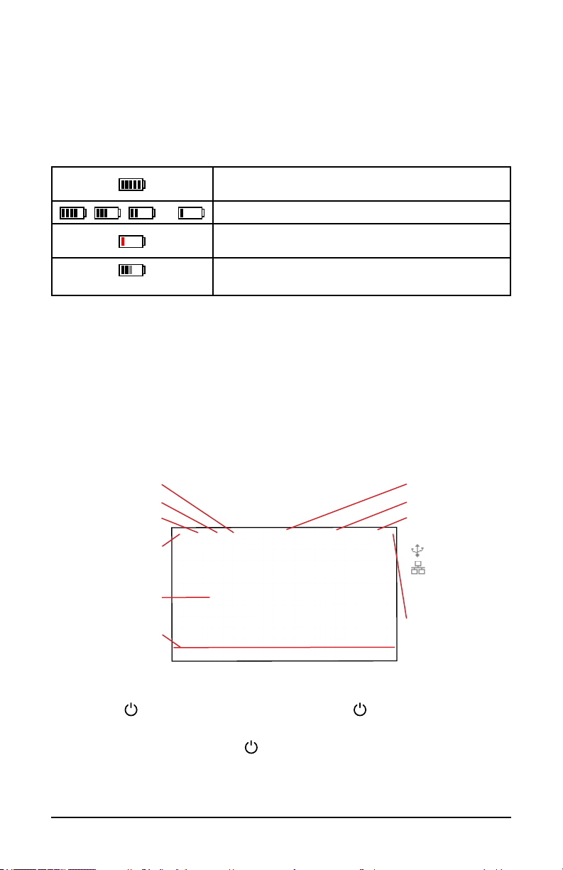
The instrument’s display has a battery indicator icon that shows the battery’s
status and remaining charge.
Indicates that the battery is fully charged or that the
new battery’s charge is unknown
, , , or
(one bar blinking)
Indicates the battery charge level
Indicates that the battery is fully discharged. You will
need to charge the battery completely
Indicates that the battery is charging
A message will be displayed if the remaining charge of the battery is too low to
ensure correct operation of the instrument.
If you do not connect the instrument to an external power source, the instrument
will turn o one minute after the message is displayed.
2.6 DISPLAY UNIT
The 8345 has a large, color, touch-screen display unit (WVGA).
At the top of the screen, the status bar reports the instrument’s status.
An example of a typical screen is below.
Screenshot
Help
Mode
Return to main screen
Frequency measured
Date and time
Connection:
USB drive
USB link
Ethernet link
Display for the chosen
mode and function
Available functions
(mode-dependent)
Battery charge level
2.7 ON/OFF BUTTON
Use the button to turn the instrument on. The button will blink orange
while the instrument is turning on.
When the battery is charging, the
steady green when the battery is fully charged.
If the instrument’s power is cut o suddenly or automatically, a message will be
displayed the next time it is turned on.
10 Power Quality Analyzer PowerPad® IV Model 8345
button will blink green. The button will show

Press the button again to turn the instrument o
The instrument will request conrmation if it is recording or metering energy,
recording transients or alarms, or capturing an inrush current.
If the power-o command is conrmed, the recordings will nalize, and the
instrument will turn o. Recordings will automatically resume the next time that
the instrument turns on.
If the instrument is o while connected to external power, the battery will charge.
If the display freezes and the instrument does not turn o by pressing
the
button, you can force it to turn o by holding the button for 10
seconds. If the instrument is forced to turn o, any in-progress recordings
on the SD card could be lost.
2.8 KEYPAD
2.8.1 Mode Buttons (Purple Buttons)
These nine buttons are used to access specic modes:
Button Function See §
Waveform mode § 5
Harmonic mode § 6
Power mode § 7
Energy mode § 8
Trend mode § 9
Transient mode § 10
Inrush Current mode § 11
Alarm mode § 12
Monitoring mode § 13
2.8.2 Navigation Buttons
Button Function
Power Quality Analyzer PowerPad® IV Model 8345 11
Directional buttons
Conrm button
Return button

2.8.3 The Other Buttons
Button Function See §
Conguration button § 4.3
Screenshots button § 14
Help button § 15
2.8.4 The Function Buttons (8 Yellow Buttons)
The functions of the yellow buttons depend on the selected mode and context.
A button’s function for each screen is shown at the bottom of the display.
2.9 INSTALLING THE COLOR CODES
To identify the cords and the input terminals, you can color-code them using the
colored markers provided with the instrument.
1. Break o the sector and insert it into the two holes near the terminal. The
large sectors are for the current terminals, and the small sectors are for the
voltage terminals.
2. Clip two rings of the same color onto the ends of the cord that will connect
to the terminal.
You have 12 sets of dierent-colored markers to match the instrument with the
color codes in eect.
Large sectors for current terminals Small sectors for voltage terminals
The same color as
the terminal
12 Power Quality Analyzer PowerPad® IV Model 8345

2.10 MEMORY CARD
The instrument is delivered with a formatted SD card that is essential for
recording measurements.
The instrument accepts SD (SDSC), SDHC, and SDXC memory cards in FAT16,
FAT32, or exFAT format.
To install a new SD card, you will need to:
1. Open the elastomer cap marked SD.
2. Press on the SD card to remove it from its slot. The red indicator will turn o.
3. Slide the new SD card into the slot until you feel a click. The red indicator
will turn on.
4. Then, close the elastomer cap.
L2 L3
L1
N
L1
N
L2 L3
SD card indicator
Lock the SD card by sliding its tab to the LOCK position when you
remove it from the instrument. Unlock the SD card by sliding its tab
away from the LOCK position before inserting it into the instrument.
LOCK
Locked SD cardUnlocked SD card
LOCK
Power Quality Analyzer PowerPad® IV Model 8345 13

2.11 PROP
The back of the instrument has a retractable prop to hold it at a 60° angle.
NOTE: Do not insert the leads into the terminals while the instrument is
supported by the prop, or the prop could become damaged. The prop is
designed only for viewing the display and interacting with the interface
from dierent angles.
2.12 MAGNETIZED HOOK (OPTIONAL)
The magnetized hook can suspend the instrument from the top of a door or
attach it to a metallic surface.
Magnet
Hand strap
14 Power Quality Analyzer PowerPad® IV Model 8345

3. CONFIGURATION
The conguration screen allows you to set up specic congurations for the
instrument’s parameters and every measurement mode.
Press the button to access the conguration screen
Press the button to congure the measurements
Press the button to congure the instrument
You must congure your instrument before use.
3.1 NAVIGATION
The 8345’s screens are available using the navigation buttons or touch screen.
1. To congure the instrument, use the navigation buttons (◄, ►, ▲, ▼) or the
touch screen to select and modify the parameters.
2. Use the
3. Use the
If you are wearing gloves, we recommend using the navigation buttons instead
of the touch screen.
button to conrm the highlighted selection.
button to cancel or to return to the previous screen.
3.2 USERS
The 8345 allows three dierent users to congure the instrument and
measurements. The conguration for each user prole is saved, so multiple
users can use the 8345 without reconguring the instrument for each user.
1. Press
Power Quality Analyzer PowerPad® IV Model 8345 15
to access the user proles.

2. Press . The USER PROFILE screen displays the conrm button icon
next to the rst user prole being selected (see below image). Use the (▲,
▼) directional buttons, to select a dierent user prole.
3. Press
directional buttons to select the user name eld, and press
enable the eld name. Now you can edit the name.
4. Enter your desired username (up to 8 characters long) using upper- and
lower-case letters (A-Z), numbers (0-9), and symbols (@, -, _, and . ), all
accessible by the touch screen.
5. Press
6. Press
7. Press
which now shows the updated name entered with the conrm icon next to it.
to access the details of the user prole. Use the (◄, ►)
again to
to erase the previous character.
to erase the selected character and all following characters.
to submit the change and return to the USER PROFILE screen
16 Power Quality Analyzer PowerPad® IV Model 8345

3.3 CONFIGURING THE INSTRUMENT
Except for the display and language, the instrument’s conguration
cannot be changed if the instrument is recording or metering energy,
recording transients or alarms, or capturing an inrush current.
3.3.1 Language
1. Press on the setup screen to enter the language selection screen.
2. Use the navigation buttons or touch screen to highlight the language for
your instrument.
3. To conrm the selected language, use the
button or the touch screen to
select the desired language option.
Refer to § 1.6 for more information.
3.3.2 Date and Time
Press to set the date and time
73 available time zones
♦
Press to choose from
For Time source, choose between NTP server, GPS, and Manual for your
desired method to set the date and time
For Date/Time, enter the date and time if on Manual mode; otherwise, this
eld is grayed out and view only
For NTP server, enter the NTP server address that you would like to use to
set the date and time
For Date format, select your desired date format from MM/DD/YY,
DD/MM/YY, and YY/MM/DD
For Time format, choose whether to display time in 12 h or 24 h format
For Daylight Saving Time, check the box to apply Daylight Saving Time
Power Quality Analyzer PowerPad® IV Model 8345 17
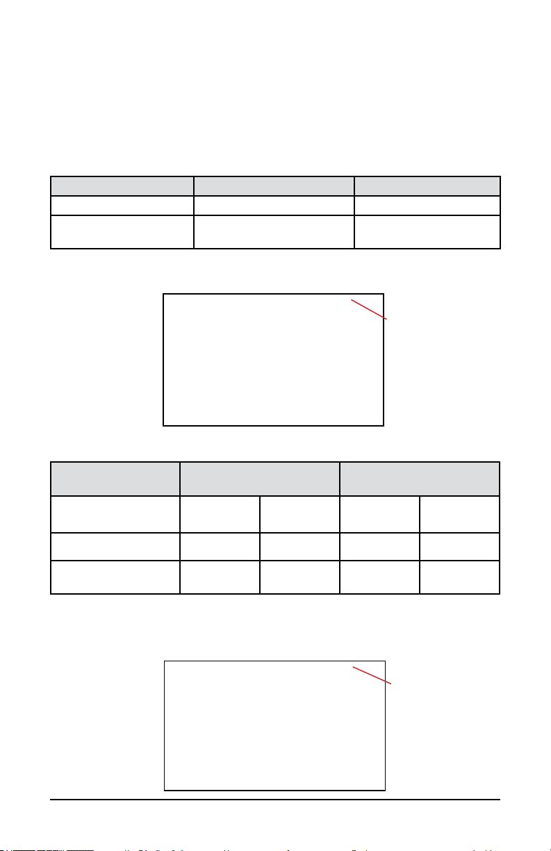
3.3.2.1 GPS Mode
The GPS mode is necessary to guarantee that your instrument is Class A (per
IEC 61000-4-30). The instrument must have access to the GPS satellites at
least once to receive the date and time. The instrument could take up to 15
minutes to synchronize.
The instrument will maintain accuracy in the following situations, even if the
satellites are no longer accessible.
Satellites in view Maximum drift (Class A) Drift (Model 8345)
None ±1 s / 24 h ±24 ms / 24 h
One or more
±16.7 ms vs UTC
at all times
±60 ns / 1 s
corrected at all times
To avoid time discontinuities, you cannot set the time automatically when a
recording is in progress.
Status of time
synchronization via GPS
The satellite reception status is indicated by an icon (
GPS
synchronization
Satellites in view None One or more None One or more
No recording
Recording in progress
Not synchronized Synchronized
) in the status bar.
After 40 days with no exposure to a GPS satellite, the synchronization icon ( )
will change to unsynchronized (
).
3.3.2.2 NTP Mode
Time synchronization
by NTP:
Not synchronized
Synchronized
Synchronized and
recording in progress
18 Power Quality Analyzer PowerPad® IV Model 8345
1. If you choose time synchronization by NTP, enter the address of the NTP
server in the NTP server eld (Example: 0.fr.pool.ntp.org)
2. Select your country’s time zone.
3. Connect the instrument to the server via Ethernet connector or Wi-Fi.
The time synchronization status is indicated by an icon (
) in the status bar.
3.3.3 Display
Press to open the conguration menu for the display
3.3.3.1 Colors of the Voltage Curves
1. Press
2. Choose a color for each of the 3 phases and neutral.
In night mode, the background changes from white to black.
3.3.3.2 Colors of the Current Curves
1. Press
2. Choose one color for each of the 4 current inputs.
In night mode, the background changes from white to black.
to choose the colors of the voltage curves.
to choose the colors of the current curves.
3.3.3.3 Screen Brightness and Auto-O
You can activate or deactivate the screen’s auto-o. If activated, the screen will
automatically turn o after 10 minutes with no user action, which helps prolong
battery life. If a recording is in progress, the screen will not automatically turn o.
Select to adjust the screen’s brightness and auto-o
Press any button to turn the screen back on
3.3.4 Memory
The screen indicates the content of the SD card or USB drive .
The bars at the top and at the right side of the screen show the SD card’s used
space in black and the remaining space in white. The SD card’s total size is to
the right of the bar.
Power Quality Analyzer PowerPad® IV Model 8345 19
The SD card’s
remaining memory
The total size of the
SD card
The SD card’s
used memory
1. Press to manage the external memory’s content.
2. To view an item in detail, select it and press
3. Press
to eject the SD card or USB drive.
.
You must eject the SD card before removing it from the instrument;
otherwise, you risk losing its content.
When the SD card is removed, the red SD card present indicator will turn o and
the
symbol will be displayed in the status bar.
You can erase all or part of the memory’s content.
Memory used by
the selected items
1. Select the items from memory that you would like to erase. Once selected,
the display will indicate each item’s size to the right of the selected item on
the same line. The yellow bar at the right side of the screen indicates the
total memory used by the selected items.
2. To view a selected item in detail, press
3. Press
4. Press
To delete the other users, press
To copy all or part of the SD card’s contents to a USB drive, press
to erase the selection. The instrument will request conrmation .
to conrm or to abort.
.
20 Power Quality Analyzer PowerPad® IV Model 8345

3.3.5 Network
The instrument’s connection status is indicated in the top right of the display.
Connection status
Press
Press
to congure the Ethernet link
to congure the email
Press
Press
to congure the Wi-Fi link
to connect to the IRD server
notications
Only one link (Ethernet or Wi-Fi) can be activated at a time.
3.3.5.1 Ethernet Link
The
symbol indicates that the link is active.
The
symbol indicates that the link is inactive and that it can be activated.
Press in the screen’s bottom right to deactivate an active link before
modifying it
If no link is active, no action is needed.
Press to activate the link
For DHCP (Dynamic Host Conguration Protocol), select whether to update
the IP address automatically or manually
If selected, the instrument will request the IP address and other parameters
from a DHCP server and will generate an IP address automatically if no
DHCP server replies.
If deselected, you must assign the IP address and parameters manually.
3.3.5.2 Wi-Fi Link
The
symbol indicates that the link is active.
Power Quality Analyzer PowerPad® IV Model 8345 21

The symbol indicates that the link is inactive and can be activated.
Press in the screen’s bottom right to deactivate an active link before
modifying it
If no link is active, no action is needed.
For SSID, choose the network to connect to the instrument
If your network is not shown, press
For Password, enter the password for the selected SSID, if required
For DHCP (Dynamic Host Conguration Protocol), select whether to update
to search for available networks
the IP address automatically or manually
If selected, the instrument will request the IP address and other parameters
from a DHCP server and will generate an IP address automatically if no
DHCP server replies
If deselected, you must assign the IP address and parameters manually
Press to activate the link
3.3.5.3 Email
For Recipient, enter an email address to receive notications if an alarm
threshold is exceeded
3.3.5.4 IRD Server
An Internet Relay Device (IRD) is a protocol used for communication between
two peripherals located in two distinct sub-networks, like a PC and measuring
instrument. Each peripheral connects to an IRD server, and the server links the
two peripherals together.
We recommend utilizing the IRD Server for conguring test measurements, and
directly connecting to a PC for generating reports involving large packets of data.
22 Power Quality Analyzer PowerPad® IV Model 8345
 Loading...