

Page 1
Megohmmeter
Models 6550 & 6555
Quick Start Guide
ENGLISH
www.aemc.com
®
CHAUVIN ARNOUX GROUP
Page 2

Statement of Compliance
Chauvin Arnoux®, Inc. d.b.a. AEMC® Instruments
certifies that this instrument has been calibrated
using standards and instruments traceable to
international standards.
We guarantee that at the time of shipping your
instrument has met its published specifications.
An NIST traceable certificate may be
requested at the time of purchase, or obtained
by returning the instrument to our repair and
calibration facility, for a nominal charge.
The recommended calibration interval for this
instrument is 12 months and begins on the date of
receipt by the customer. For recalibration, please
use our calibration services. Refer to our repair
and calibration section at www.aemc.com.
Serial #: ________________________________
Catalog #: 2130.31 / 2130.32
Model #: 6550/6555
Please fill in the appropriate date as indicated:
Date Received: _________________________________
Date Calibration Due:
_______________________
Chauvin Arnoux®, Inc.
d.b.a AEMC® Instruments
www.aemc.com
Page 3
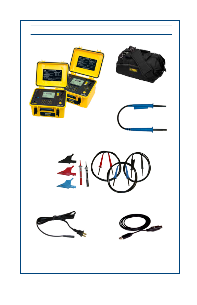
PRODUCT PACKAGING
Shipping Contents:
10kV Megohmmeter Model 6550
Cat. #2130.31
or
15kV Megohmmeter Model 6555
Cat. #2130.32
(1) Large Classic Tool Bag
Cat. #2133.73
15kV Jumper Lead
Cat. #2151.15
Set of 3 color-coded (red/blue/black) 9 ft (15kV) integral leads and alligator clips (1000V CAT IV),
Also Included:
• 4 GB USB Stick (DataView
• 2x9.6V NiMH batteries (Cat. #2140.19 each)
set of 2 color-coded test probes (red/black 1000V CAT IV)
115V US Power Cord
Cat. #5000.14
Cat. #2151.14 & Cat. #2152.23
®
/User Manual)
Optical USB Cable
Cat. #2135.41
USB STICK: DataView® software and complete user manual for the Model 6550
& 6555 can be located on the USB stick supplied with the instrument.
Page 4
Thank you for purchasing a Megohmmeter Model 6550/6555.
For best results from your instrument and for your safety, read the enclosed operating instructions
carefully and comply with the precautions for use. These products must be only used by qualied
and trained users.
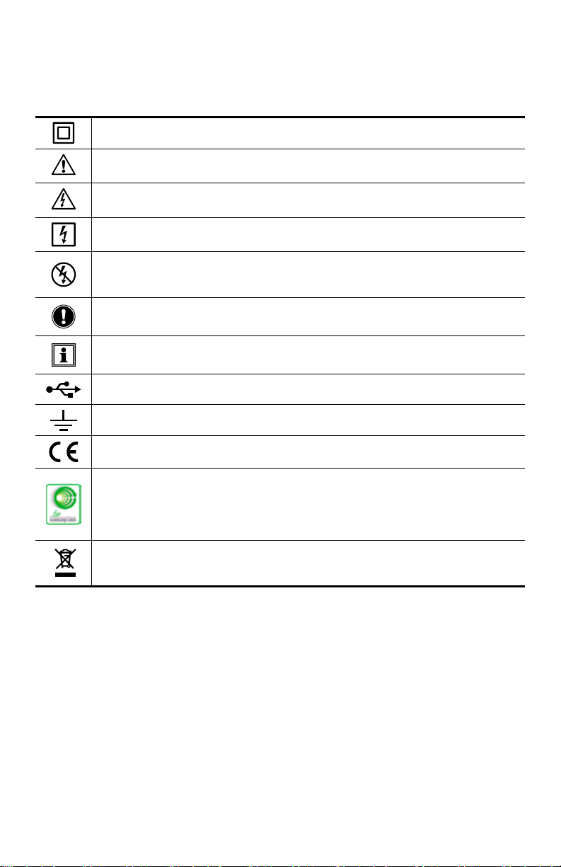
Signies that the instrument is protected by double or reinforced insulation.
CAUTION - DANGER! Read the User Manual.
Risk of electric shock. The voltage at the parts marked with this symbol may be dangerous.
Refers to a type A current sensor. This symbol signies that application around and
removal from HAZARDOUS LIVE conductors is permitted.
Refers to a type B current sensor. Do not apply around or remove from HAZARDOUS LIVE conductors without additional protective means (de-energizing the circuit
or wearing protective clothing suitable for high voltage work).
Important instructions to read and to fully understand.
Useful information or tip to read.
USB socket.
Ground/Earth.
The CE marking guarantees conformity with European directives and with regulations
covering EMC.
Chauvin Arnoux® Inc. d.b.a. AEMC® Instruments has adopted an Eco-Design
approach in order to design this instrument. Analysis of the complete lifecycle has
enabled us to control and optimize the eects of the product on the environment. In
particular this instrument exceeds regulation requirements with respect to recycling
and reuse.
The trash can with a line through it means that in the European Union, the product
must undergo selective disposal for the recycling of electric and electronic material,
in compliance with Directive WEEE 2002/96/EC.
Page 5

Precautions Before Use
This instrument and its accessories comply with safety standards IEC 61010-1, IEC 61010031, and IEC 61010-2-030 for voltages of 1000V in Category IV at an altitude of less than
2000m, indoors, with a degree of pollution of not more than 2. Failure to observe the safety
instructions may result in electric shock, re, explosion, and destruction of the instrument and
of the installations.
• The operator and/or the responsible authority must carefully read and clearly
understand the various precautions to be taken in use. Sound knowledge and a keen
awareness of electrical hazards are essential when using this instrument.
• If the instrument is used other than as specied, the protection it provides may be
compromised, thereby endangering you.
• Do not use the instrument on networks of which the voltage or category exceeds those
mentioned.
• Do not use the instrument if it seems to be damaged, incomplete, or poorly closed.
• Before each use, check the condition of the insulation on the leads, housing, and
accessories. Any item of which the insulation is deteriorated (even partially) must be set
aside for repair or scrapping.
• Use only the leads and accessories supplied. Using leads (or accessories) of a lower
voltage or category reduces the voltage or category of the combined instrument and
leads (or accessories) to that of the leads (or accessories).
• Use personal protection equipment systematically.
• Keep your hands away from the terminals of the instrument.
• When handling the leads, test probes, and alligator clips, keep your ngers behind the
physical guard.
• As a safety measure, and to avoid interference, do not move and do not handle the
leads during measurements.
Denition of Measurement Categories (CAT)
• CAT IV - 3-Phase at utility connection, outdoor conductors:
- Origin of installation, or where low-voltage connection is made to utility power
- Electricity meters, primary overcurrent protection equipment
- Outside and service entrance, service drop from pole to building, runs between
meter & panel
- Overhead line to detached building, underground line to well pump
• CAT III - 3-Phase distribution, including single-phase commercial lighting:
- Equipment in xed installations, such as switchgear and polyphase motors
- Bus and feeder in industrial plants
- Feeders and short branch circuits, distribution panel devices
- Appliance/equipment outlets with short connections to service entrance
• CAT II - Single-phase, receptacle-connected loads:
- Appliances, portable tools, and other similar light industrial/household loads
- Outlet and long-branch circuits
- Outlets at more than 30 ft from CAT III source
- Outlets at more than 60 ft from CAT IV source
Page 6

Charging the Battery
Fully charge the battery before the rst use.
Charging must be conducted at a temperature between 32° and 86°F (0° and 30°C).
The batteries automatically begin recharging when the instrument is connected to AC power.
Only use the supplied AC power adapter to recharge the batteries.
NOTE: A full recharge of a completely discharged battery takes 6 to 10 hrs approx.
SET-UP
MR
Step
Voltage
V RAMP
V VAR
V FIXED
OFF
Control Features
1
1000V CAT III
600V CAT IV
( 2500V )
To recharge the battery:
• Set the rotary switch to the OFF position.
• Connect the supplied power cord to the
instrument and AC power.
> 90 VAC
• During charging, the following is
< 260 VAC
50/60 Hz
displayed: The percentage charge of
each of the batteries, their voltages, their
charging currents, their temperatures, and
the charging times.
2
110-230V 50/60 Hz
80 VA max
SET-UP
V RAMP
V VAR
V FIXED
OFF
4
3
MR
Step
Voltage
5
6
TEMP
HELP
ALARM
MEM
CONFIG
FILTER
DISPLAY
GRAPH
START
STOP
15
kV MEGOHMMETER
MODEL 6555
7
1. Safety connection terminals +, G and -.
2. Graphical, digital LCD.
3. Power receptacle for recharging the
batteries.
4. USB connection for communication
with a PC.
8
5. Seven-position rotary function switch.
6. Navigation buttons for moving the cursor,
selecting and changing values.
7. START/STOP measurement button.
8. Eight function buttons.
Page 7
Button Functions
ICON DESCRIPTION
TEMP
ALARM
HELP /
Enters temperature and humidity information and calculate temperature
corrected resistance
Enables/Disables the alarms
Displays Help information; Enables/Disables the backlighting of the display
MEM Stores the measurements
CONFIG
Conguration of the measurement parameters
DISPLAY Switch between screens
FILTER Smoothing of the measurements
GRAPH Switch graph mode ON/OFF
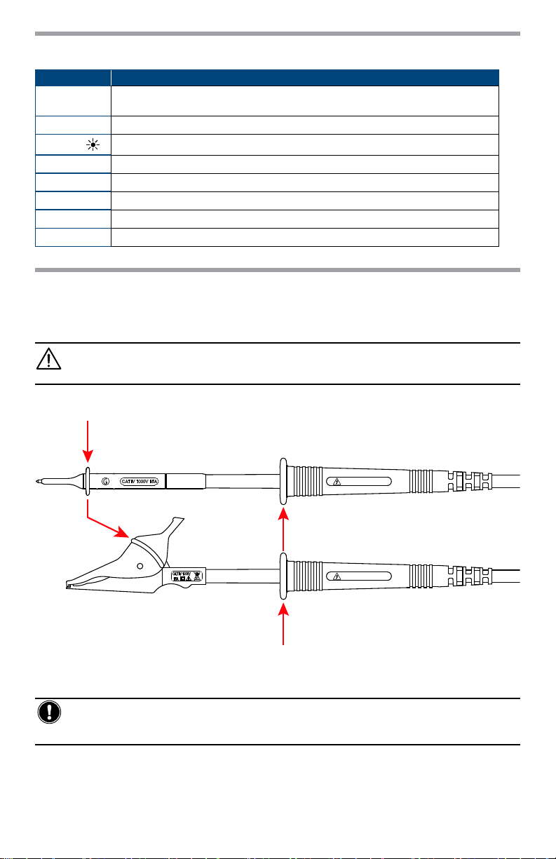
Using the Leads
Specic leads are supplied with the instrument. To use them, attach either the test probes or alligator clips (supplied with the instrument).
NOTE: These accessories have hand guards. For safety reasons, the user’s hands must
always be behind the hand guard.
Always keep hands behind this protective guard:
• Voltages ≤1000V
• Insulation using a test voltage ≤ 5000V
15 kV max
15 kV max
• On insulation measurements with a test voltage ≥ 5000V
Measurements of voltages ≥1000V on supply lines should be made using the test probes only,
with the user’s hands behind the hand guard on the lead.
WARNING: The leads with large clips (automobile battery charger type) proposed as
accessories should not be used for line voltage measurements because their jaws are not
insulated.
Page 8

Instrument Configuration (SET-UP)
NOTE: The instrument is factory congured. For most measurements, simply choose the test
voltage and press the START/STOP button.
However, conguration can be performed by one of these two methods:
• The SET-UP function allows overall conguration of the instrument independently of which
measurement functions are chosen.
• The CONFIG button allows conguration of the chosen measurement function before and
during a measurement.
NOTE: A conguration made by either method, is updated for both (SET-UP function or CONFIG
button).
PARAMETER FUNCTION
Buzzer
Auto-Power OFF
Baud Rate
Date
Time
Temperature Unit
Instrument Number
Firmware
Sets the audible level of beeps: 1, 2, 3, or O (no sound).
If enabled, the instrument will turn o after 5 minutes of no activity.
Sets the data rate of the serial interface to 9600, 19200, 38400 or
57600 bauds.
Sets the date in yyyy-mm-dd format.
Sets the time in hh:mm format.
Chooses the temperature unit: Celsius or Fahrenheit.
Indicates the number of the instrument (cannot be modied).
Indicates the two version numbers of the rmware in the instrument (cannot be modied).
Installing DataView
DO NOT CONNECT THE INSTRUMENT TO THE PC BEFORE INSTALLING THE SOFTWARE AND DRIVERS.
1. Insert the USB stick into an available USB port (wait for driver to be installed).
2. If Autorun is enabled, an AutoPlay window should appear. If Autorun is disabled, it will be
necessary to open Windows Explorer, then locate and open the USB stick drive labeled
“DataView” to view the les on the drive.
3. In the AutoPlay window, select “Open folder to view les”.
4. Double-click on Setup.exe from the opened folder view to launch the Dataview® setup
program.
NOTE: For more information on using DataView®, refer to the Model 6550 & 6555 user manual
that is supplied on the USB stick or the Help le within the software.
®
Updating Software & Firmware
Free software and rmware updates are available on our website: www.aemc.com
DataView® can also be updated by selecting “Update” from the Help menu within the software.
Page 9

Repair and Calibration
To ensure that your instrument meets factory specications, we recommend that it be scheduled
back to our factory Service Center at one-year intervals for recalibration, or as required by other
standards or internal procedures.
For instrument repair and calibration:
You must contact our Service Center for a Customer Service Authorization Number (CSA#).
This will ensure that when your instrument arrives, it will be tracked and processed promptly.
Please write the CSA# on the outside of the shipping container. If the instrument is returned
for calibration, we need to know if you want a standard calibration, or a calibration traceable to
N.I.S.T. (Includes calibration certicate plus recorded calibration data).
Ship To: Chauvin Arnoux®, Inc. d.b.a. AEMC® Instruments
15 Faraday Drive
Dover, NH 03820 USA
Phone: (800) 945-2362 (Ext. 360)
(603) 749-6434 (Ext. 360)
Fax: (603) 742-2346 or (603) 749-6309
E-mail: repair@aemc.com
(Or contact your authorized distributor)
Costs for repair, standard calibration, and calibration traceable to N.I.S.T. are available.
NOTE: You must obtain a CSA# before returning any instrument.
Technical and Sales Assistance
If you are experiencing any technical problems, or require any assistance with the proper
operation or application of your instrument, please call, mail, fax or e-mail our technical support
team:
Chauvin Arnoux®, Inc. d.b.a. AEMC® Instruments
200 Foxborough Boulevard
Foxborough, MA 02035 USA
Phone: (800) 343-1391
(508) 698-2115
Fax: (508) 698-2118
E-mail: techsupport@aemc.com
www.aemc.com
NOTE: Do not ship instruments to our Foxborough, MA address.
Page 10

Limited Warranty
The Model 6550 & 6555 is warranted to the owner for a period of two years from the date of
original purchase against defects in manufacture. This limited warranty is given by AEMC®
Instruments, not by the distributor from whom it was purchased. This warranty is void if the
unit has been tampered with, abused or if the defect is related to service not performed by
AEMC® Instruments.
Full warranty coverage and registration is available on our website: www.aemc.com.
Please print the online Warranty Coverage Information for your records.
What AEMC® Instruments will do:
If a malfunction occurs within the warranty period, you may return the instrument to us for
repair, provided we have your warranty registration information on le or a proof of purchase.
AEMC® Instruments will, at its option, repair or replace the faulty material.
Register your product online at www.aemc.com
Warranty Repairs
What you must do to return an Instrument for Warranty Repair:
First, request a Customer Service Authorization Number (CSA#) by phone or by fax from our
Service Department (see address below), then return the instrument along with the signed
CSA Form. Please write the CSA# on the outside of the shipping container. Return the
instrument, postage or shipment pre-paid to:
Ship To: Chauvin Arnoux®, Inc. d.b.a. AEMC® Instruments
15 Faraday Drive
Dover, NH 03820 USA
Phone: (800) 945-2362 (Ext. 360)
(603) 749-6434 (Ext. 360)
Fax: (603) 742-2346 or (603) 749-6309
E-mail: repair@aemc.com
Caution: To protect yourself against in-transit loss, we recommend you insure your returned
material.
You must obtain a CSA# before returning any instrument.
Page 11

Page 12

06/17
99-MAN 100399 v3
Chauvin Arnoux
®
, Inc. d.b.a. AEMC® Instruments
15 Faraday Drive • Dover, NH 03820 USA • Phone: (603) 749-6434 • Fax: (603) 742-2346
www.aemc.com
 Loading...