

Page 1
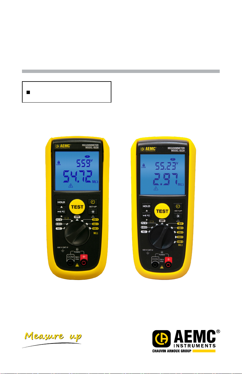
Megohmmeter
Models 6528 and 6529
User Manual
True Megohmmeter
®
ENGLISH
www.aemc.com
Page 2

Copyright © Chauvin Arnoux®, Inc. d.b.a. AEMC® Instruments. All rights reserved.
No part of this documentation may be reproduced in any form or by any means (including electronic
storage and retrieval or translation into any other language) without prior agreement and written consent
from Chauvin Arnoux®, Inc., as governed by United States and International copyright laws.
®
Chauvin Arnoux
, Inc. d.b.a. AEMC® Instruments
15 Faraday Drive • Dover, NH 03820 USA
Tel: (800) 945-2362 or (603) 749-6434 • Fax: (603) 742-2346
This documentation is provided “as is,” without warranty of any kind, express, implied, or otherwise.
Chauvin Arnoux
but does not warrant the accuracy or completeness of the text, graphics, or other information contained
in this documentation. Chauvin Arnoux
®
, Inc. has made every reasonable effort to ensure that this documentation is accurate;
®
, Inc. shall not be liable for any damages, special, indirect,
incidental, or inconsequential; including (but not limited to) physical, emotional or monetary damages
due to lost revenues or lost prots that may result from the use of this documentation, whether or not
the user of the documentation has been advised of the possibility of such damages.
®
Chauvin Arnoux®, Inc, AEMC
, and DataView® are registered trademarks of AEMC® Instruments.
Page 3

Statement of Compliance
Chauvin Arnoux®, Inc. d.b.a. AEMC® Instruments certifies that this
instrument has been calibrated using standards and instruments
traceable to international standards.
We guarantee that at the time of shipping your instrument has met its
published specifications.
An NIST traceable certificate may be requested at the time of
purchase, or obtained by returning the instrument to our repair and
calibration facility, for a nominal charge.
The recommended calibration interval for this instrument is 12 months
and begins on the date of receipt by the customer. For recalibration,
please use our calibration services. Refer to our repair and calibration
section at www.aemc.com.
Serial #: ______________________________
Catalog #: 2126.54 / 2126.55
Model #: 6528 / 6529
Please fill in the appropriate date as indicated:
Date Received: _________________________
Date Calibration Due: ____________________
Chauvin Arnoux®, Inc.
d.b.a AEMC
www.aemc.com
®
Instruments
Page 4
MEASUREMENT CATEGORIES
770 V
Thank you for purchasing the True Megohmmeter® Model 6528 or 6529. For best results
with your instrument:
■ Read this user manual carefully
■ Respect precautions for use
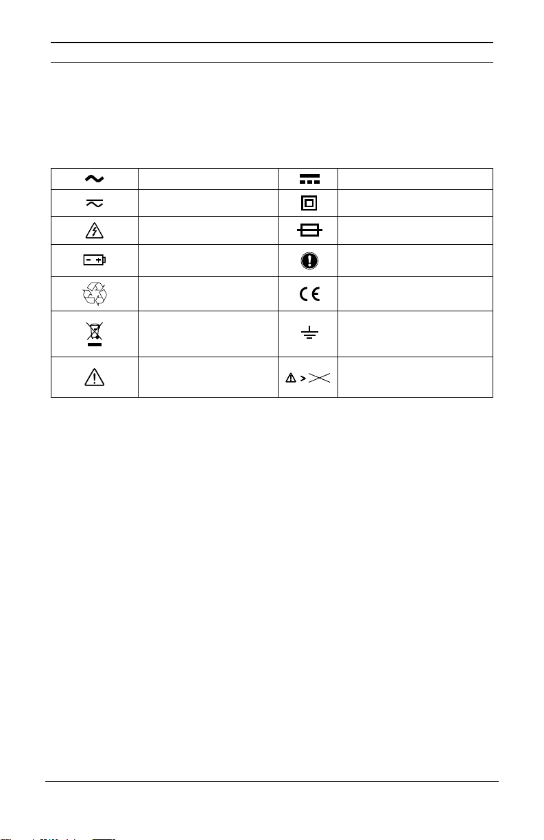
AC - Alternating current DC - Direct Current
AC or DC Double insulated
Shock Hazard Fuse
Battery
Instrument follows
recycling directives
Instructions that must be
read and understood
Comply with US directives
Sorting for the recycling
of electric and electronic
Earth Ground
waste
Danger Hazard
Voltage on the instrument
should not exceed 770VRMS
Definition of Measurement Categories (CAT)
■ CAT IV: Test and measurement circuits connected to the source of the building’s
low-voltage network installation.
Example: Measurement on equipment installed upstream of the main fuse or
building installation cut-off switch.
■ CAT III: Test and measurement circuits connected to parts of the building’s low
voltage network installation.
Example: Measurement on distribution switchboards (including secondary meters),
the circuit breakers, cabling including cables, busbars, junction boxes, circuit
breakers, power outlets in the xed installation and industrial instruments and
other equipment such as motors permanently connected to the xed installation.
■ CAT II: Test and measurement circuits directly connected to points of use (power
outlets and other similar points) on the low voltage network.
Example: Measurement on circuits in network for household appliances, portable
tools and other similar instruments.
4
Megohmmeter Models 6528/6529
Page 5

PRECAUTIONS FOR USE
Failure to comply with safety instructions can create a risk of electric shock, re, explosion and destruction
the instrument or the installations. If the instrument is used other than as specied in this User Manual,
the protection provided by the instrument may be impaired.
■ The operator and/or the responsible authority must carefully read and clearly understand the
various precautions to be taken in use.
■ Before using the instrument, make sure it functions properly by measuring a known voltage and a
known insulation resistor, and check continuity by short circuiting both test leads.
■ Do not use the instrument in an explosive atmosphere or in the presence of inammable gas or
smoke.
■ Do not use the instrument on networks with a rated voltage or category higher than those listed in
this manual.
■ Respect the maximum rated voltages and currents between terminals and in relation to the earth.
■ Do not use the instrument if it seems damaged, incomplete, or incorrectly closed.
■ Before each use, check the condition of the cable insulation, the instrument, and its accessories.
All elements on which the insulation is damaged (even partially) must be put out of service for
repair or disposed as waste.
■ Use cables and accessories for voltage according to IEC 61010-031 and measurement categories
at least equal to those of the instrument. If not, an accessory of a lower category reduces the
category of the combined megohmmeter plus the accessory to that of the accessory.
of
■ Respect the environmental conditions of use.
■ Strictly comply with the fuse specications. Disconnect all cables before opening the fuse access
cover.
■ Do not modify the instrument, and, do not replace components using equivalent parts. Repairs
and adjustments must be performed by qualied, approved personnel.
■ Replace the battery as soon as the
before opening the battery access cover.
■ Use personal protection equipment (PPE) when conditions require it.
■ Keep your hands and ngers away from the unused instrument terminals. When handling sensors
or test probes, do not place ngers beyond the physical nger guard.
5
symbol appears on the display. Disconnect all cables
Megohmmeter Models 6528/6529
Page 6

TABLE OF CONTENTS
1.INTRODUCTION ............................................................................................... 7
1.1 Receiving Your Shipment ................................................................................................................... 7
1.2 Ordering Information .......................................................................................................................... 7
1.3 Accessories ........................................................................................................................................ 8
1.4 Replacement Parts ............................................................................................................................ 8
2.OVERVIEW ...................................................................................................... 8
2.1 Description ......................................................................................................................................... 8
2.2 Insulation Resistance Testing Principal of Operation ......................................................................... 9
2.3 Megohmmeter Models 6528 & 6529 — Front View ........................................................................... 9
2.4 TEST Button and Function Keys ...................................................................................................... 10
2.5 Instrument Display ........................................................................................................................... 10
2.6 Terminals ...........................................................................................................................................11
2.7 Conguration Mode ...........................................................................................................................11
2.8 Alarm Buzzer ................................................................................................................................... 12
2.9 Permanent Mode ............................................................................................................................. 12
2.10 Backlight (BL) ................................................................................................................................. 12
2.11 Firmware Version ............................................................................................................................ 12
2.12 Alarm Functions and Indicators ...................................................................................................... 12
3.OPERATION ................................................................................................... 14
3.1 Battery Installation ........................................................................................................................... 14
3.2 Instrument Check ............................................................................................................................. 14
3.3 Power Supply and Battery Life ......................................................................................................... 14
3.4 Stand, Door or Magnetic Mount ....................................................................................................... 15
3.5 AC+DC or DC Voltage ..................................................................................................................... 15
3.6 Continuity ......................................................................................................................................... 16
3.7 Resistance ....................................................................................................................................... 17
3.8 Insulation Resistance Tests.............................................................................................................. 18
4. MAINTENANCE .............................................................................................. 24
4.1 Cleaning ........................................................................................................................................... 24
4.2 200mA Fuse Test ............................................................................................................................. 24
4.3 Battery and Fuse Replacement ....................................................................................................... 24
5. GENERAL SPECIFICATIONS .......................................................................... 25
6. ELECTRICAL SPECIFICATIONS ..................................................................... 26
6.1 General Condition of Reference ...................................................................................................... 26
6.2 AC/DC Voltage Measurement .......................................................................................................... 26
6.3 Ground Bond Continuity Measurement ............................................................................................ 26
6.4 Ground Bond Resistance Measurement .......................................................................................... 26
6.5 Insulation Resistance Specication ................................................................................................ 27
7. REPAIR AND CALIBRATION ........................................................................... 28
8. TECHNICAL AND SALES ASSISTANCE .......................................................... 28
9. LIMITED WARRANTY ..................................................................................... 29
Page 7
1.INTRODUCTION
1.1 Receiving Your Shipment
Upon receiving your shipment, make sure that the contents are consistent with the packing list. Notify your
distributor
the carrier and notify your distributor at once, giving a detailed description
damaged packing container to substantiate your claim.
1.2 Ordering Information
Megohmmeter Model 6528 (Digital, 250V, 500V, 1kV, 420K-Ohm, V, Continuity, Alarm &
Timer) .................................................................................................................................. Cat. #2126.54
Megohmmeter Model 6529 (Digital, 50V, 100V, 250V, 500V, 1kV,420k-Ohm, V, Continuity, Alarm &
Timer, PI/DAR) ....................................................................................................................Cat. #2126.55
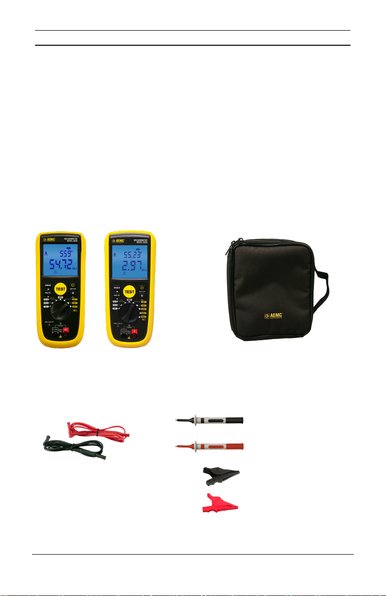
Both models include soft carrying case, set of (2) 5 ft color-coded silicone leads, (2) color-coded
alligator clips, (2) color-coded test probes (red/black), {Rated 1000V CAT IV, UL V2}, (6) 1.5V AA batteries
and a user manual.
of any missing items. If the equipment appears to be damaged, le a
of any damage. Save the
claim immediately with
(1) of the following Megohmmeter Models:
Model 6528 Cat. #2126.54 or
Model 6529 Cat. #2126.55
Lead – set of (2), 5 ft silicone color-coded
(red/black) with 4mm straight/right angle
banana plugs (Rated 1000V CAT IV, UL)
Cat. #5000.94
Also includes 6 AA batteries and a user manual.
7
(1) Pouch – replacement for Models 1026, 6528, & 6529
(7 x 8.5 x 2”)
Cat. #2117.73
Probe – black test probe (Rated
1000V CAT IV, 15A, UL V2)
Cat. #5000.97
Probe – red test probe (Rated
1000V CAT IV, 15A, UL V2)
Cat. #5000.98
Clip – safety alligator – black
(Rated 1000V CAT IV, 15A, UL V2)
Cat. #5000.99
Clip – safety alligator – red (Rated
1000V CAT IV, 15A, UL V2)
Cat. #5100.00
Megohmmeter Models 6528/6529
Page 8
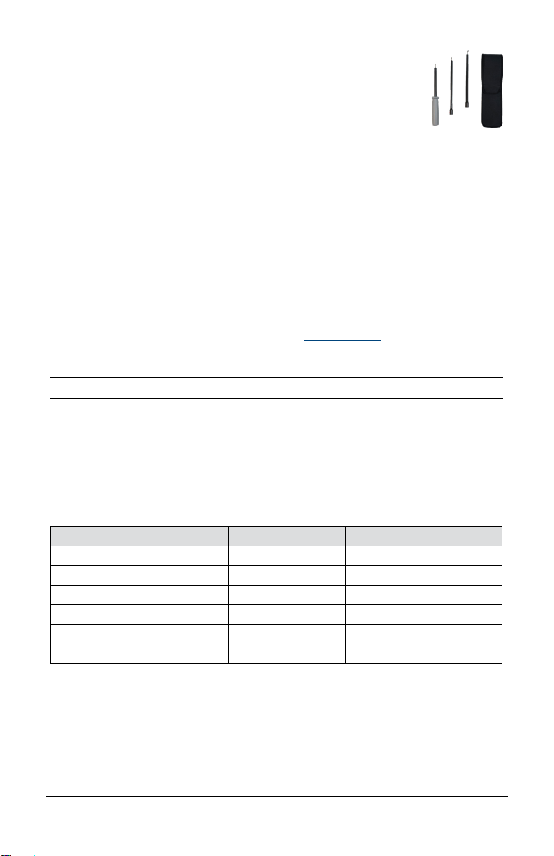
1.3 Accessories
Continuity Probe for use with Megohmmeters and Installation
Testers .................................................................................................Cat. #2138.54
1.4 Replacement Parts
Pouch – replacement for Models 1026, 6528, & 6529 (7 x 8.5 x 2”) ................................. Cat. #2117.73
Lead – set of (2), 5 ft silicone color-coded (red/black) with 4mm straight/right angle banana plugs
(Rated 1000V CAT IV, UL) ..................................................................................................Cat. #5000.94
Fuse – set of 2, FF, 200mA, 1000V, 10kA, 6x32mm .......................................................... Cat. #2971.04
Probe – black test probe (Rated 1000V CAT IV, 15A, UL V2) ............................................ Cat. #5000.97
Probe – red test probe (Rated 1000V CAT IV, 15A, UL V2) ............................................... Cat. #5000.98
Clip – safety alligator – black (Rated 1000V CAT IV, 15A, UL V2) .....................................Cat. #5000.99
Clip – safety alligator – red (Rated 1000V CAT IV, 15A, UL V2) ......................................... Cat. #5100.00
For accessories and replacement parts, visit our store at www.aemc.com.
2.OVERVIEW
2.1 Description
The Megohmmeter Models 6528 and 6529 are portable measuring instruments with digital displays.
They are powered by batteries. These instruments can check the safety of electrical insulation. For
example, they can be used to test new insulation before they are powered up, check existing insulation
in a power-off condition, or troubleshoot potential faulty insulation.
Features include:
Model 6528 Model 6529
Insulation test voltages 250, 500, and 1000V 50, 100, 250, 500, and 1000V
Insulation Resistance
PI and DAR ratios calculation
Continuity measurement
Resistance measurement
Programmable alarms
8
–
Megohmmeter Models 6528/6529
Page 9
2.2 Insulation Resistance Testing Principal of Operation
Insulation resistance measurement is based on Ohm’s Law. By applying a known DC voltage and then
measuring the current owing, the instrument can determine the value of the resistance. In principle, the
value of the insulation resistance is very high, but not innite. Therefore, by measuring the low current
owing, the instrument indicates the insulation
This resistance characterizes the quality of the insulation and
resistance value, providing a result in kΩ, MΩ, or GΩ.
provides a good indication of the risks
of leakage currents.
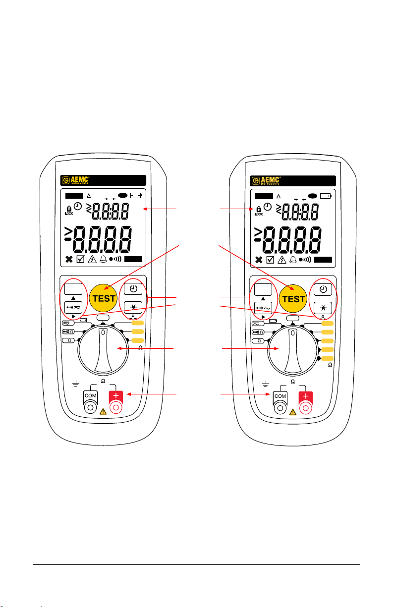
2.3 Megohmmeter Models 6528 & 6529 — Front View
HOLD
HOLD
V
Ω
kΩ
600 V CAT IV
REL
OFF
Ω
FUSED
700 V
max
MEGOHMMETER
MODEL 6528
Ω
P
0
NOISE
SET-UP
V%
mA
1000 V
V
kΩ
GΩ
MΩ
Ω
0
250 V
500
MΩ
MEGOHMMETER
MODEL 6529
Ω
HOLD
REL
Backlit LCD
AC
+
DC
display unit
PI
DAR
TEST button
P
0
V%
mA
AC
+
V
DC
kΩ
GΩ
MΩ
NOISE
Four Function
Keys
V
Test Modes
Six (Model 6528)
Eight (Model 6529)
Fused
Test Lead Terminals
HOLD
V
Ω
kΩ
600 V CAT IV
OFF
Ω
FUSED
700 V
max
SET-UP
Ω
0
50 V
250 V
500 V
1000 V
M
V
100
9
Megohmmeter Models 6528/6529
Page 10
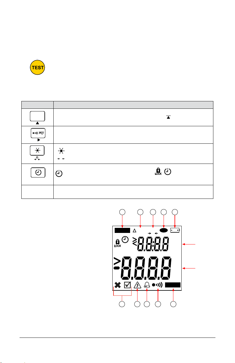
2.4 TEST Button and Function Keys
0
Ω
0
SET-UP
2.4.1 TEST Button
Pressing the TEST button starts an insulation measurement. It also serves to conrm a programmed
threshold.
• Performs battery voltage check (§3.2)
• In resistance measurement, it is used to enter/exit the DMR mode and record
the reference measurement (§3.7.1)
• Starts insulation resistance test (§3.8)
2.4.2 Function Keys
KEY DESCRIPTION
HOLD
Freezes/unfreezes the measurement on the display. To unfreeze the display press
HOLD key again. In SET-UP mode, the function of the key
parameters.
Toggle between AC+DC and DC (§3.5)
Activate/deactivate audible continuity indicator (§3.6) and insulation alarm (§3.7)
is to cycle through
Ω
▲, ►
2.5 Instrument Display
1. Indicates the measurement is on hold.
2. Indicates the Differential Mode Resistance
(DMR) or relative mode function is active in
a resistance measurement.
3. Indicates the resistance of the leads is
compensated in a continuity measurement.
4. Indicates auto-off is deactivated.
5. Indicates the remaining battery life.
6. Indicates that the measurement is within
or outside of the alarm threshold set point.
7. Indicates the presence of a hazardous voltage.
8. Indicates the alarm is active in the insulation
or DMR measurement mode.
9. Indicates the audible buzzer is activated.
10. Indicates a voltage interference in a conti
or resistance measurement.
(short press <2s) Activate/deactivate backlight (§2.10)
(long press >2s) Perform lead compensation for continuity checks (§3.6.1)
SET-UP (long >2s press): congure settings (§2.7)
(short press <2s): select type of insulation test (
6529)) (§3.8)
Navigate the conguration menu (§2.7)
nuity
1 2 3 4 5
Ω
HOLD
REL
0
6 7 8 9 10
, , PI, DAR (Model
P
V%
mA
V
kΩ
GΩ
AC
+
DC
Secondary
Display
Primary
Display
MΩ
NOISE
10
Megohmmeter Models 6528/6529
Page 11

2.6 Terminals
SET-UP
The instrument has two measurement terminals: + (positive) and COM (common).
Ω
FUSED
700 V
max
2.7 Configuration Mode
Conguration mode enables you to set several options for the instrument. To open conguration
mode, turn the rotary switch to OFF. Then press and hold down the SET-UP
key for >2s while
turning the rotary switch to any position. The symbol ConF appears on the LCD.
V
Ω
kΩ
OFF
>2s
6528 rotary switch shown
250 V
500
1000 V
MΩ
V
Pressing the ▲ key cycles through parameters, and the ► key selects the setting for the displayed
option. Available parameters:
Insulation test mode buzzer enabled/disabled (§2.8)
P
1st press on ▲
Permanent mode enabled/disabled (§2.9)
2nd press on
▲
Backlighting enabled/disabled (§2.10)
3rd press on ▲
Firmware version number (display only, §2.11)
4th press on ▲
Return to the rst screen.
Switch the instrument off by turning the rotary switch to OFF. All of your changes are applied the next
time the instrument is turned ON.
11
Megohmmeter Models 6528/6529
Page 12

2.8 Alarm Buzzer
P
P
To enable/disable the audible Alarm buzzer in Insulation mode:
OFF
1. Turn the rotary switch to
Press and hold down the
2.
momentarily
3. The
displays
symbol appears on the display. If this is set to ON, press ► to select
restart the instrument, the Alarm Buzzer
.
SET-UP
ConF
key for >2s turning the rotary switch to any position. The LCD
to indicate the insturment is in conguration mode.
will be disabled.
OFF
. When you
2.9 Permanent Mode
To help prolong battery life, by default the instrument’s auto-off is activated and turns off the display if
it is idle for 10 minutes. Press the TEST button to awaken the instrument.
To deactivate auto-off:
1. Turn the rotary switch to
2.
Press and hold down the
momentarily
displays
3. Press ▲ until
OFF.
SET-UP
ConF
appears. If this is set to
key for >2s turning the rotary switch to any position. The LCD
to indicate the insturment is in conguration mode.
OFF
, press ► to select ON.
When you restart the instrument, the auto-off is deactivated and the
appears on the LCD indicating
the Permanent mode is active.
2.10 Backlight (BL)
To help prolong battery life, by default the instrument’s Backlighting mode is deactivated (or auto-off of
backight is activated) and after 2 minutes the backlighting is switched off.
If you want the backlighting to stay on at all times:
1. Turn the rotary switch to
2. Press and hold down the
The LCD momentarily displays
3. Press ▲ until
OFF
.
SET-UP
key for >2s while turning the rotary switch to any position.
ConF
to indicate the insturment is in conguration mode.
appears. If this is set to
OFF
, press ► to select ON. The next time the instrument
is switched on, automatic switching off of the backlighting will be deactivated and the backlighting
will stay on at all times once the
key has been pushed while the instrument is actively on.
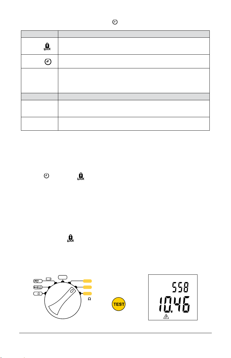
2.11 Firmware Version
To display the rmware version number currently running on the instrument:
1. Turn the rotary switch to OFF.
2. Press and hold down the SET-UP key for >2s while turning the rotary switch to any position. The
LCD will display ConF.
3. Press ▲ until SOFT appears; the rmware version appears in the primary display.
2.12 Alarm Functions and Indicators
12
Megohmmeter Models 6528/6529
Page 13

2.12.1 Alarm Functions
SET-UP
The alarm functions make it possible to rapidly conrm that the readings are OK, without looking at
the display. You can adjust the alarm function default settings by adjusting the thresholds.
Function
Insulation 50V* 50kΩ from 10kΩ to 399.9MΩ
Insulation 100V* 100kΩ from 20kΩ to 399.9MΩ
There are 7 alarm thresholds:
To program a threshold, set the switch to the desired function, long press the SET-UP key for >2s
and release it when the beep sounds. The instrument displays the current threshold with the rst
digit blinking.
Use the ▲ key to set the digit and the ► key to go to the next digit. When all 4 digits have been set,
choose the unit number. Conrm by pressing the TEST button.
OFF
V
Ω
kΩ
6528 rotary switch shown
To enable Alarm Mode, press the Alarm Buzzer
If the measurement is below the alarm threshold, the meter emits a continous beep, the backlighting
lights red and the
250V
500
V
1000V
MΩ
symbol is displayed.
×
Insulation 250V 250kΩ from 50kΩ to 3.999GΩ
Insulation 500V 500kΩ from 100kΩ to 3.999GΩ
Insulation 1000V 1000kΩ from 200kΩ to 9.99GΩ
Continuity 1Ω 1Ω or 2Ω
Resistance DMR 5% from 0.1 to 3999.9%
* Model 6529 only
>2s
Default Threshold Programmable Threshold
kΩ
HOLD
key. The symbols and are displayed.
13
Megohmmeter Models 6528/6529
Page 14

3.OPERATION
3.1 Battery Installation
Place the batteries in the instrument as follows:
1. Use a Phillips screwdriver to remove the battery cover
screw on the back of the instrument (see illustration
on right).
2. Install the batteries, respecting polarity. Requires six
AA (LR6) batteries.
3. Replace the battery cover and tighten the screw.
3.2 Instrument Check
We recommend performing the following steps
when using the instrument for the rst time, or
after a long period without use.
1. Start the instrument. Ensure all display segments are displayed.
2. Perform a Continuity check (§3.6). Ensure the LCD displays >42.0Ω with no input connected.
Then short circuit both terminals, the display should show 0Ω.
3. Turn the rotary switch to V, check a known voltage (e.g., a battery) and ensure that the
voltage is correct.
4. Disconnect from the voltage source, and press the TEST button. The instrument’s battery voltage
is displayed. Ensure this is above 6.6V.
5. Turn the rotary switch to an insulation voltage setting (§3.7), and check a known resistor that
is within the
6. When all the steps above produce expected results, you can start using the instrument.
measurement range for the test voltage selected.
measured
3.3 Power Supply and Battery Life
The power supply is six 1.5V alkaline batteries (type AA or LR6). Nominal voltage is 6.6 to 9.6V. Below
6.6V the instrument will not turn on.
■ Battery life for insulation measurements: Average battery life for insulation measurement
(according to IEC61557-2 clause 6.7) is 2000 measurements with new batteries at room
temperature (5s ON, 25s OFF).
■ Battery life for voltage and resistance measurements: Average battery life for voltage
and resistance with new batteries at room temperature @ 400kΩ is > 300h.
■ Battery life for continuity checking: Average battery life for continuity checking (according
to IEC 61557-4 clause 6.6) is > 6000 measurements with new batteries at room temperature
(5s ON, 25s OFF). For shorter continuity tests (0.8s ON, 10s OFF) battery life is > 40,000 tests.
■ Battery voltage: To check the battery voltage, press and hold the TEST button with the switch
set to the V position.
14
Megohmmeter Models 6528/6529
Page 15

3.4 Stand, Door or Magnetic Mount
For convenience, the instrument can be used in
different positions:
■ With the stand - simply pull the back stand
down to free it from its slot, then fold it and
insert the end in the upper available slot.
■ The stand can be placed on the top of a
door or other similar surface by positioning
the stand over the top edge as shown.
■ The stand is equipped with magnets
allowing
the instrument to be attached
to a metal surface.
3.5 AC+DC or DC Voltage
The instrument measures AC+DC or DC voltage, to minimize risk when measuring an
unknown voltage. Measure AC+DC voltage rst. Be sure to respect the rated voltage
and category.
If the measurement departs from the measurement range, the instrument displays OL.
1. Turn the rotary switch to the V position.
2. Toggle between AC+DC or DC voltage measurement
by pressing the
key.
AC
+
V
DC
V
DC
Toggle
between
AC + DC
3. Connect the red test lead to the
black test lead to the COM terminal.
4. Measure the voltage by attaching the test leads to the
desired test points of the circuit.
Note: When the rotary switch is set to V, you can
display the instrument’s battery voltage by pressing and
holding down the TEST key with no voltage present
on the test leads. Releasing the key returns to voltage
measurement mode.
15
+ terminal and the
and DC
Megohmmeter Models 6528/6529
Page 16
3.5.1 Voltage Error Indicators
■ If the measurement is outside of the measurement range, the instrument displays OL.
3.6 Continuity
To avoid electrical shock and damage to the instrument when measuring resistance or continuity
in a circuit, ensure power to the circuit is turned OFF and all capacitors are discharged.
The measurement can be aected by (1) impedances of additional operating circuits connected in
parallel, or (2) transient currents.
In Continuity mode the instrument outputs a current above 200mA @ 2Ω between the + and COM
terminals. The voltage across the circuit under test is measured by the instrument; this voltage is then
used to calculate resistance (R = V/I).
1. Turn the rotary switch to
2. The continuity threshold can be either 1Ω or 2Ω. To change this, press SET-UP
displays the threshold setting. Press ▲ to change this, then press TEST to exit SET-UP
3. Connect the red test lead to the
4. To compensate leads see §3.6.1.
5. Check continuity by connecting the leads to the desired point of the circuit. If resistance is under
the threshold, the buzzer will sound, and
the resistance is above the threshold, the backlight will light up red, the buzzer won’t sound, and the
LCD displays
on the secondary display (§2.5). To activate the audible alarm signal, press the
symbol is displayed
lets you check that the continuity
Secondary Display
. The LCD displays the measured continuity on its primary display and test current
×
Primary Display
If you change the leads without redoing the compensation, the reading can become negative.
Ω.
for >2s. This
mode.
+
terminal and the black test lead to the COM terminal.
will display on the LCD designating a short circuit. If
and a beep is emitted when the measurement is below the threshold. This
measurement is OK just by listening, without looking at the display.
REL
REL
%
Ω
key. The
%
Ω
16
Megohmmeter Models 6528/6529
Page 17

3.6.1 Compensation of the Measurement Leads
Ω
0
Ω
0
Short the input terminals by touching them together. Then press the
key and hold it down for >2s.
The LCD should display 0Ω. If current is 0 mA when the terminals are shorted, verify the fuse is good.
NOTE: If the resistance of the leads is >5Ω, compensation is not possible.
To remove test lead compensation, press
disabled by pressing the alarm
key.
for >2s with the test leads open. The buzzer can be
3.6.2 Continuity Alarm Indicators
■ The alarm is always active in continuity measurement.
■ The instrument gives you a choice of two alarm thresholds: 1Ω or 2Ω.
■ If the measurement is below the threshold, the
■ If the measurement exceeds the threshold, the backlighting lights turn red and the
is displayed.
symbol is displayed.
symbol
×
3.6.3 Continuity Error Indicators
■ If the measurement is beyond the measurement range, the instrument displays >42.00Ω.
■ If during the measurement the
symbol appears on the LCD, transient currents are
affecting the measurement. Ensure the circuit under measurement is de-energized.
■ When the measurement current is <200mA, the measurement is still correct but is no longer
compliant with the IEC standard continuity measurements.
■ The instrument displays the AC+DC voltage. If it is >30V, the
symbol is displayed to warn
the user that the voltage on the terminals is hazardous and the instrument emits a pulsed beep.
■ If there is a voltage of more than 0.4V on the object to be tested, the instrument displays .
3.7 Resistance
To perform a resistance test, the instrument outputs a DC voltage and measures the current across
the circuit under test. The instrument then calculates the resistance.
To avoid electrical shock and damage to the instrument when measuring resistance or continuity in
a circuit, ensure power to the circuit is turned OFF and all capacitors are discharged.
3.7.1 Differential Mode Resistance (DRM) Mode
In the resistance measurement mode, there is a very useful feature
called the Differential Resistance Mode (DRM). It can be used as
an incoming inspection tool, a radiant heat element qualifying tool
or a quality check on production lines to name a few.
This is a valuable feature to compare successive measurements to
a previously measured
falls outside a congured threshold percentage
alarm will occur.
Start by setting the threshold in %
1. Turn the rotary switch to the kΩ position.
2. Press and hold the SET-UP
percentage appears in the LCD secondary display area, with
“reference” resistance. If the measurement
, a visual and audible
key for >2s. The threshold
V
Ω
kΩ
OFF
the rst digit blinking.
3. You can adjust the percentage by pressing the ▲ to increment
the blinking digit and the ► to advance to the next digit.
17
6528 rotary switch shown
Megohmmeter Models 6528/6529
250 V
500
1000 V
MΩ
V
Page 18

4. The threshold percentage can be set from 0.1% to
399.9%; default is 5%. When nished setting the threshold
percentage, press TEST to exit SET-UP mode.
5. Connect the red lead to the + terminal and the black lead
to the COM terminal.
6. Connect the test leads to the device to be used as the reference
resistance. The resistance measurement will appear in
the
primary display area.
7. Press the TEST button to accept that as the reference
value. The ΔRel symbol will appear and the percentage
difference will appear on the top line of the secondary
display indicating the instrument is in DRM mode.
As you take subsequent measurements, the difference between
the measurement and the reference is displayed both in ohms
(primary display (§2.5)) and as a percentage (secondary
display (§2.5)).
If the difference exceeds the threshold percentage, an alarm
activates with a red back lit display and an audible buzzer (if
enabled) indicating the out of tolerance condition.
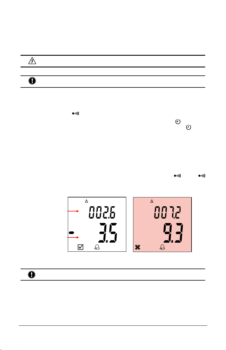
3.7.2 Resistance Mode Alarm Indicators
■ Before starting an insulation measurement, pressing
the
key activates the alarm. The alarm threshold
is displayed, along with the
■ If the measurement exceeds the threshold, the
symbol is displayed.
■ If the measurement is below the threshold, the
instrument emits a continuous beep, the backlight
turns red and the
3.7.3 Resistance Mode Error Indicators
■ If there is a voltage of more than 0.4V on the object to be tested, the instrument displays .
■ If the object to be tested is at a hazardous voltage, >30V, the symbol is displayed and the
instrument emits a pulsed beep.
■ If the measurement is outside of the measurement range, the instrument displays >420.0kΩ.
symbol is displayed.
×
and symbols.
DRM
Mode
REL
REL
%
M
%
%
Ω
Ω
Ω
3.8 Insulation Resistance Tests
To avoid electrical shock and damage to the instrument when measuring resistance or continuity
in a circuit, ensure power to the circuit is turned OFF and all capacitors are discharged.
In Insulation Resistance mode the instrument outputs a DC voltage. This voltage depends on the
resistance to be measured. The device measures the voltage and current present between the two
terminals and determines the value of R=V/I.
You can perform up to ve types of resistance tests, depending on instrument model. By default, the
instrument is in “unlocked” untimed test mode. In this mode, the test begins when you press the
TEST button, and ends when you release it. This mode is typically used to run short “spot” tests.
18
Megohmmeter Models 6528/6529
Page 19
The other test types are selected via the SET-UP key:
KEY
1st press
2nd press
3rd press
Exit
PI
KEY
4th press DAR
5th press TEST
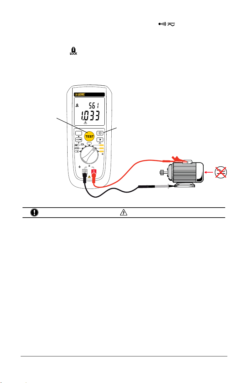
3.8.1 Untimed Test (Including Unlocked and Locked)
1. Turn the rotary switch to an insulation voltage setting, Choices are 250 V, 500 V, 1000 V (available
on both the Models 6528 and 6529), and 50 V and 100 V (available on Model 6529 only). The test
voltage to select depends on the operating voltage of the device to be tested.
2. To run an unlocked test, skip this step and continue with step 3. To lock the TEST button, press the
SET-UP
3. To set an Alarm (§2.12).
4. Use the leads to connect the system to be tested to the instrument’s terminals. The test sample
must be powered down and discharged. When testing insulation, the typical connection is negative
(black) lead to conductor and positive (red) lead to ground or the outer insulation of the test sample.
DESCRIPTION
Lock the TEST button. In this mode, after you start the measurement, it
continues without requiring you to keep the TEST button pressed. The test will
run until you stop it, or when 40 minutes have passed.
Activate timed test mode. You can set the test duration between 1 second and
39:59 minutes.
Exit timed text mode (Model 6528).
Enable the PI function (Model 6529). This is used to calculate the polarization
index (the ratio of the measurement at T2 [default 10 minutes] to the measurement
at T1 [default 1 minute]).
DESCRIPTION
Enable the DAR function (Model 6529). This is used to calculate the dielectric
absorption ratio (the ratio of the measurement at T2 [default 1 minute] to the
measurement at T1 [default 30 seconds]).
Exit timed test mode (Model 6529).
key once. The icon appears on the LCD.
5. Press the TEST button to start the test.
If you are running an unlocked test, hold down the TEST button until the displayed measurement
is stable.
If you are running a
Note that if the instrument detects a voltage greater than 30V in the system under test, pressing the
TEST button has no effect because the test will be prohibited.
When the insulation measurement stabilizes, it appears on the primary display (§2.5). The secondary
display (§2.5) shows the test voltage.
V
Ω
kΩ
6528 rotary switch shown
19
test, release the TEST button.
OFF
250 V
500
1000 V
MΩ
V
Megohmmeter Models 6528/6529
V
MΩ
Page 20
6. When performing insulation measurement, you can press the key to enable the alarm
feature. If the
measurement falls below the alarm threshold, the alarm will activate. To set alarm
threshold (§2.12).
7. At the end of the test, either release the TEST button (for unlocked tests) or press the TEST button
a second time (for
tests). The instrument stops generating the test voltage and discharges
the device being tested. During this process the discharging voltage value is displayed to indicate
residual voltage. The measured value will remain on the display until you make another
measurement,
press the HOLD key, or turn OFF the instrument. You can also start another measurement
immediately by a long press on the TEST button.
MEGOHMMETER
MODEL 6528
P
V
Press TEST to start
measurement
HOLD
V
Ω
kΩ
600 V CAT IV
Model 6528 shown
Do not disconnect the instrument while the symbol is still displayed.
MΩ
Timer
SET-UP
Ω
0
OFF
250V
V
500
1000V
MΩ
Ω
FUSED
700 V
max
3.8.2 Timed Test (Including PI and DAR)
Both the Model 6528 and Model 6529 can perform timed tests that stop automatically after a dened
duration. In addition, the Model 6529 can perform polarization index (PI) and dielectric absorption
ratio (DAR) tests.
Polarization index is a useful indicator of motor insulation health. It can identify the accumulation of
contaminants as well as any physical damage to the insulation itself. The test involves applying
positive charge to a motor’s conductors and a negative charge to the motor frame therefore
polarizing
the insulation. This test essentially measures the change over time. Healthy clean insulation
will charge over time resulting in the decrease of induced current and an increase in insulation
resistance.
Unhealthy insulation will result in a at to decreasing insulation resistance over time.
The PI test compares the measurement of insulation resistance at two points in time. The most prominent
used time points are at 1 and 10 minutes. Model 6529 defaults to these two test points labeled as T1
and T2. The instrument allows user programming of both time points if necessary. Acceptable values
can be programmed between 1 second and 30 minutes for each test point. The time for T2 must be at
least 1 second longer than T1.
The polarization index is calculated by dividing the insulation resistance value at point in time T2 (e.g.,
10-min) by the insulation resistance value taken at point in time T1 (e.g., 1-min).
a
20
Megohmmeter Models 6528/6529
Page 21
IEEE-43 recommends that good insulation will exhibit an increase in resistance at the 10-minute point
that should be at least two times greater than the measurement taken at the one-minute point. Therefore,
healthy insulation will exhibit a PI ratio of 2 or higher. Newer insulation material can progress through
the absorption phase very quickly and therefore display a PI ratio of 1.
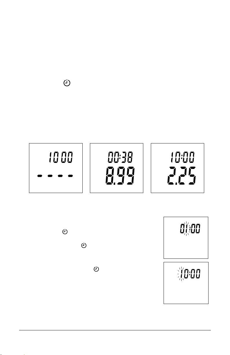
3.8.2.1 Conducting a Polarization Index (PI) Test (Model 6529)
1. Select the desired insulation resistance test voltage using the rotary switch.
2. Turn the rotary switch to an insulation voltage setting. Choices are 50V, 100V, 250V, 500V, and
1000V. The test voltage to select depends on the voltage of the installation to be tested.
3. Press the SET-UP
key three times until you see PI on the secondary display (§2.5) along with
the test run time.
4. Press and hold the TEST button until the test begins.
5. The secondary display will then indicate a countdown timer showing the remaining time to complete
the test. The primary display (§2.5) will show a real time value of the insulation resistance measurement
in progress.
6. At the conclusion of the test the secondary display will show PI and the elapsed test time.
7. The primary display will show the PI ratio.
PI
PI
Ω
M
PI
3.8.2.2 Programming the Polarization Index T1 and T2 Test Time Points
1. Select the desired insulation resistance test voltage using the rotary
switch.
2. Press the SET-UP
key three times until you see PI on the top line
of secondary display along with the test run time.
3. Press and hold the SET-UP
key >2s until the Alarm threshold is
shown. Press SET-UP key again until T1 appears and the leading time
digit begins to blink. You can adjust the time for T1 by using the ▲ to
increment the blinking digit and ► to advance to the next digit.
4. Once completed press the SET-UP
key again.
5. The time T2 time will now appear in the display with the rst digit
blinking repeat the ▲ and ► arrow sequence to adjust the desired
time for T2.
6. Press the test button TEST button to lock-in the new times for T1 and T2.
PI
PI
T1
T2
21
Megohmmeter Models 6528/6529
Page 22
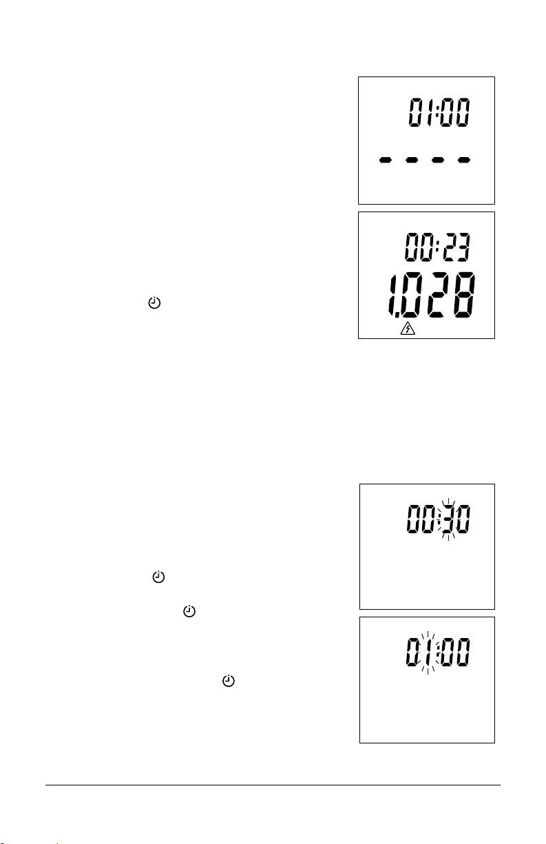
3.8.2.3 Conducting a Dielectric Absorption Ratio (DAR) Test
The dielectric absorption ratio test is typically accomplished by
measuring the insulation
interval and comparing it to the insulation resistance
at the 60 second time interval. The instrument allows user
programming of both time points if necessary.
As with the PI ratio, these two time points are labeled T1 and T2.
The DAR ratio is then calculated by dividing the T2 measurement
(e.g., 60 seconds) by the T1 measurement (e.g., 30 seconds).
Generally, ratios of 1.25 or less are considered questionable.
Ratios between 1.25 and 1.6 are considered acceptable and ratios
higher than 1.6 are considered good.
1. Turn the rotary switch to an insulation voltage setting. Choices
are 250V, 500V, 1000V (available on both the Models 6528
and 6529) and 50V and 100V (available on the Model 6529
only). The test voltage to select depends on the voltage of the
installation to be tested.
2. Press the SET-UP
secondary display along with the test run time.
3. Press and hold the TEST button until the test begins.
The top line of the secondary display will indicate a countdown
timer showing the remaining time to complete the test. The bottom
primary display will show a real time value of the insulation
resistance measurement in progress.
At the conclusion of the test the secondary display will show DAR
and the elapsed test time.
The bottom primary display will show the DAR ratio.
3.8.2.4 Programming DAR the T1 and T2 test time points
The instrument allows for user programming both time points if
necessary. Acceptable values can be programmed between
1 second and 30 minutes for each test point. The time for T2
must at least 1 second longer than T1.
1. Select the desired insulation resistance test voltage using the
rotary switch.
2. Press the SET-UP key four times until you see DAR on
the top line of
3. Press and hold the SET-UP key >2s until the Alarm threshold
is shown. Press SET-UP key again until T1 appears and the
leading time digit
by using the ▲ arrow to increment
arrow to advance to the next digit.
4. Once completed press the SET-UP
5. The time T2 will now appear in the secondary display with the
rst digit blinking; repeat the ▲ and ► arrow sequence to
adjust the desired time for T2.
6. Press the TEST button to lock-in the new times for T1 and T2.
resistance taken at the 30 second time
measurement
key four times until you see DAR in the
display along with the test run time.
begins to blink. You can adjust the time for T1
the blinking digit and the ►
key again.
DAR
DAR
DAR
DAR
T1
T2
22
Megohmmeter Models 6528/6529
Page 23
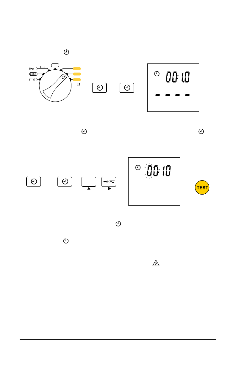
3.8.2.5 Performing a Timed Test
SET-UP
SET-UP
SET-UP
SET-UP
1. Turn the rotary switch to an insulation voltage setting. Choices are 250V, 500V, 1000V (available on
both the Models 6528 and 6529), and 50V and 100V (available on the Model 6529 only). The test
voltage to select depends on the voltage of the installation to be tested.
2. Press the SET-UP
key two times to enter duration mode.
V
Ω
kΩ
6528 rotary switch shown
3. To set an Alarm, see §2.12
4. Press and hold the SET-UP
again to display timer duration, with the leading time digit blinking. You can adjust the duration by
using the ▲ arrow to increment the blinking digit and the ► arrow to advance to the next digit.
5. The insulation measurement time of duration can be programmed from 00:01 to 39:59 (from
1 second to 40 minutes) in the duration mode
6. Press the TEST button to lock-in the new time duration for a timed test.
7. In the Timed Test
Test will stop automatically at the end of the programmed duration.
3.8.2.6 Insulation Resistance Mode Error Indicators
■ The instrument displays the AC+DC voltage. If it is >30V, the
■ If the measurement is outside of the measurement range, the instrument displays LO (if the
insulation resistance is too low to allow generation of the voltage) or >4200MΩ (for a test voltage
of 50V,* 100V*, 250V or 500V) or >11.00GΩ (for a test voltage of 1000V). (*Model 6529 only.)
■ If the instrument fails to generate a voltage, check the fuse (§4.3).
OFF
>2s
the user that the voltage on the terminals is hazardous, the instrument emits a pulsed beep and
pressing the TEST button is restricted from performing a test.
250 V
500
V
1000 V
MΩ
key >2s until the Alarm threshold is shown. Press SET-UP
HOLD
.
mode, simply long-press the TEST button to start the timed measurement.
symbol is displayed to warn
key
23
Megohmmeter Models 6528/6529
Page 24
4. MAINTENANCE
The instrument has no parts that can be replaced by personnel who are not trained and approved.
Any non-approved repair or other work, or replacement of a part by an “equivalent,” may severely
compromise safety.
4.1 Cleaning
Periodically wipe the case with a damp cloth and mild detergent. Do not use abrasives or solvents.
Dirt or moisture in the terminals can affect the readings. Dry the instrument thoroughly after cleaning
and before use.
4.2 200mA Fuse Test
To avoid electrical shock, remove the test leads and any input signals before
replacing the fuse.
1. Turn the rotary switch to Ω.
2. Short circuit both terminals.
3. If the current measurement is 0, the fuse needs to be replaced.
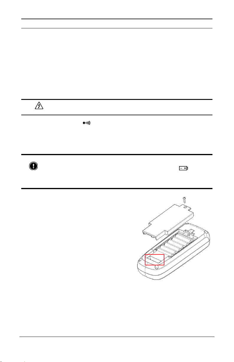
4.3 Battery and Fuse Replacement
To avoid false readings, which could lead to possible electric shock or personal injury,
replace the batteries
To prevent damage or injury, install ONLY replacement fuses with the specied amperage,
voltage, and interrupt ratings. Disconnect test leads before removing the battery cover.
Replace the batteries and fuse as follows:
1. Using a Phillips screw driver, remove the battery
cover screw on the back of the instrument.
2. Remove the old batteries.
3. Install the batteries, respecting polarity.
4. Locate the fuse in its slot near the base of the
instrument
illustration to right).
5. Using a thin athead screwdriver or similar
implement, carefully remove the fuse.
6. Insert the replacement fuse (Fast Fuse 200mA
1000V 10kA size: 6.3 x 32mm), ensuring both
ends are rmly pressed into the fuse holding
clips.
7. Replace battery door and tighten the screw.
(indicated by the red square in the
with LR6 batteries as soon as the battery indicator appears.
24
Megohmmeter Models 6528/6529
Page 25

5. GENERAL SPECIFICATIONS
I
S
T
E
D
USC
Maximum Voltage applied to terminals 700VRMS or DC
Storage temperature -40 to 140°F (-40 to 60°C)
Operating temperature 14 to 122°F (-10 to 50°C)
Temperature coefficient
Relative humidity 10% to 90%
Operating Altitude 0 to ~6500’ (0 to 2000m)
Electromagnetic compatibility EN 61326-1, EN 61326-2-2
Insulation 4000PPM/°C, Ohm/Cont 2%/10°C+2D,
V 0.3%/10°C+D
Safety
600V CAT IV, IEC 61010-2-034, IEC 61010-031,
Battery type 6x AA, NEDA 15A, IEC LR6
Battery life See §3.3
Size (H x W x L) 8.54 x 3.54 x 2.44” (217 x 90 x 62mm)
Vibration 1mm 25Hz as per IEC61557
Weight 1.68 lbs (760g)
Conformity CE, IEC61557-2, IEC61557-4, IEC61557-10
IP40 with test leads connected: EN60529
Mechanical conformity
IP20 without test leads connected: EN60529
Drop test according to IEC61010-1
Shock 0.5 J (IK04): IEC 68-2-27
Fuse F1: Fast Fuse 200mA 1000V 10kA size : 6.3 x 32
®
L
25
Megohmmeter Models 6528/6529
Page 26

6. ELECTRICAL SPECIFICATIONS
6.1 General Condition of Reference
Influencing Quantity Conditions of Reference
Ambient temperature 73.4°F ± 5.4°F (23°C ± 3°C)
Relative humidity [45%; 75%]
Electric eld ≤ 0.1V/m AC
Power supply (batteries voltage) 8 to 9V
6.2 AC/DC Voltage Measurement
Range Resolution
V
AC+DC 700V 1V ±(1.2%+1ct)
V
DC 700V 1V ±(1%+1ct)
Input impedance: 25MΩ
Common mode rejection ratio: > 60dB
Overload protection: 700VRMS or DC
Frequency: 30 to 440Hz
6.3 Ground Bond Continuity Measurement
Range Resolution
Continuity 40Ω 0.01Ω ±(1.2%+3cts)
Resistance of test leads: ≤ 0.01Ω (compensated)
Overload fuse protection by fuse: 700VRMS
Open circuit voltage: >6V and <9V
Short circuit current:
0.02-2.00Ω: ≥ 200mA
2.01-39.99Ω: between 100-200mA
6.4 Ground Bond Resistance Measurement
Range Resolution
400Ω 0.1Ω
kΩ
4kΩ 1Ω
40kΩ 10Ω
400kΩ 100Ω
Uncertainty
±(% of reading +Digits)
Uncertainty
±(% of reading +Digits)
Uncertainty
±(% of reading +Digits)
±(1.2%+3cts)
Resistance of test leads: ≤ 0.01Ω (compensated)
Overload fuse protection by fuse: 700VRMS
Open circuit voltage: 4.5V
26
Megohmmeter Models 6528/6529
Page 27

6.5 Insulation Resistance Specification
Measurement range: 0.01MΩ to 10GΩ
Test voltages:
Model 6529: 50, 100, 250, 500, 1000V
Model 6528: 250, 500, 1000V
Test voltage accuracy: +25%, 0%
Nominal current: 1mA
Auto discharge: Discharge time 2s for C=2µF
Live circuit detection:
Inhibit test if terminal voltage >30V prior to initialization
of test
Maximum capacitive load: 2µF at nominal voltage and nominal current.
Output
Voltage
50V*
(0% to +25%)
100V*
(0% to +25%)
250V
(0% to +25%)
500V
(0% to +25%)
1000V
(0% to +25%)
* Model 6529 only
Range Display Range Resolution Test current
±(% of reading
+ Digits)
Uncertainty
4MΩ
40MΩ
400MΩ
4MΩ
40MΩ
400MΩ
4MΩ
400MΩ
4GΩ
4MΩ
400MΩ
4GΩ
40MΩ
400MΩ
4GΩ
0.01 to
4.000MΩ
3.60 to
39.99MΩ
36.0 to
399.9MΩ
0.020 to
4.000MΩ
3.60 to
39.99MΩ
36.0 to
399.9MΩ
0.050 to
3.999MΩ
3.60 to
39.99MΩ
36.0 to
399.9MΩ
360 to
3,999MΩ
0.100 to
3.999MΩ
3.60 to
39.99MΩ
36.0 to
399.9MΩ
360 to
3,999MΩ
0.20 to
39.99MΩ
36.0 to
399.9MΩ
360 to
3,999MΩ
0.001MΩ
0.01MΩ
1mA @ 50kΩ
0.1MΩ
±(3%+10cts)
0.001MΩ
0.01MΩ
1mA @
100kΩ
0.1MΩ
0.001MΩ
0.01MΩ
0.1MΩ
1mA @
250kΩ
±(1.5%+10cts)40MΩ
1MΩ ±(4%+10cts)
0.001MΩ
0.01MΩ
0.1MΩ
1mA @
500kΩ
±(1.5%+10cts)40MΩ
1MΩ ±(4%+10cts)
0.01MΩ
±(1.5%+10cts)
0.1MΩ
1mA @ 1MΩ
1MΩ ±(4%+5cts)
10GΩ 3.60 to 9.99GΩ .01GΩ ±(10%+10cts)
Capacitance in parallel: <1nF
External voltage in series: 0.0V
Common mode voltage: 0.0V
27
Megohmmeter Models 6528/6529
Page 28

7. REPAIR AND CALIBRATION
To ensure that your instrument meets factory specications, we recommend that it be scheduled
back to our factory Service Center at one-year intervals for recalibration, or as required by other
standards or internal procedures. For instrument repair and calibration:
You must contact our Service Center for a Customer Service Authorization Number (CSA#). This will
ensure that when your instrument arrives, it will be tracked and processed promptly. Please write the
CSA# on the outside of the shipping container. If the instrument is returned for calibration, we need
to know if you want a standard calibration, or a calibration traceable to N.I.S.T. (Includes calibration
certicate plus recorded calibration data).
®
Ship To: Chauvin Arnoux
15 Faraday Drive • Dover, NH 03820 USA
Phone: (800) 945-2362 (Ext. 360)
(603) 749-6434 (Ext. 360)
Fax: (603) 742-2346 or (603) 749-6309
E-mail: repair@aemc.com (Or contact your authorized distributor)
Costs for repair, standard calibration, and calibration traceable to N.I.S.T. are available.
, Inc. d.b.a. AEMC® Instruments
NOTE: You must obtain a CSA# before returning any instrument.
8. TECHNICAL AND SALES ASSISTANCE
If you are experiencing any technical problems, or require any assistance with the proper operation or
application
Chauvin Arnoux
of your instrument, please call, fax, or e-mail our technical support team:
®
, Inc. d.b.a. AEMC® Instruments
Phone: (800) 343-1391
(508) 698-2115
Fax: (508) 698-2118
E-mail: techsupport@aemc.com
28
Megohmmeter Models 6528/6529
Page 29

9. LIMITED WARRANTY
The instrument is warranted to the owner for a period of two years from the date of original purchase
against defects in manufacturing. This limited warranty is given by AEMC
distributor from whom it was purchased. This warranty is void if the instrument has been tampered with,
abused, or if the defect is related to service not performed by AEMC
®
Instruments, not by the
®
Instruments.
The warranty does not apply in the following cases:
■ Inappropriate use of the equipment or use with incompatible equipment
■ Modications made to the equipment without the explicit permission of the manufacturer’s
technical staff
■ Work done on the device by a person not approved by the manufacturer
■ Adaptation to a particular application not anticipated in the denition of the equipment or not indicated
in this user’s manual
■ Damage caused by shocks, falls, or oods
Full warranty coverage and product registration is available on our website at: www.aemc.com/warranty.html
Please print the online Warranty Coverage Information for your records.
What AEMC
If a malfunction occurs within the warranty period, you may return the instrument to us for repair, provided
we have your warranty registration information on le or a proof of purchase. AEMC
®
Instruments will do:
®
Instruments will,
at its option, repair or replace the faulty material.
29
Megohmmeter Models 6528/6529
Page 30

NOTES:
30
Megohmmeter Models 6528/6529
Page 31

NOTES:
31
Megohmmeter Models 6528/6529
Page 32

10/20
99-MAN 100491 v1
Chauvin Arnoux
®
, Inc. d.b.a. AEMC® Instruments
15 Faraday Drive • Dover, NH 03820 USA
Phone: (603) 749-6434 • Fax: (603) 742-2346
www.aemc.com
 Loading...