

Page 1
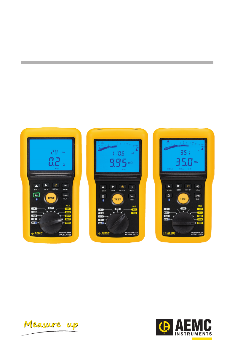
Megohmmeter
Model 6526/6532/6534
Quick Start Guide
ENGLISH
www.aemc.com
®
CHAUVIN ARNOUX GROUP
Page 2
Statement of Compliance
Chauvin Arnoux®, Inc. d.b.a. AEMC® Instruments
certifies that this instrument has been calibrated using
standards and instruments traceable to international
standards.
We guarantee that at the time of shipping your
instrument has met its published specifications.
An NIST traceable certificate may be requested at
the time of purchase, or obtained by returning the
instrument to our repair and calibration facility, for
a nominal charge.
The recommended calibration interval for this
instrument is 12 months and begins on the date of
receipt by the customer. For recalibration, please
use our calibration services. Refer to our repair and
calibration section at www.aemc.com.
Serial #: ________________________________
Catalog #: 2155.53 /2155.54 / 2155.56
Model #: 6526/6532/6534
Please fill in the appropriate date as indicated:
Date Received: _________________________________
Date Calibration Due: _______________________
Chauvin Arnoux®, Inc.
d.b.a AEMC® Instruments
www.aemc.com
Page 3
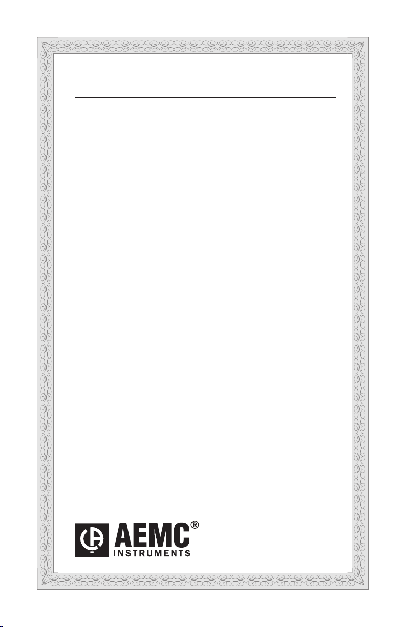
Shipping Contents:
Cat. #2155.53 / Cat. #2155.54 / Cat. #2155.55
PRODUCT PACKAGING
(1) of the following:
Megohmmeter Model 6526
Megohmmeter Model 6532
Megohmmeter Model 6534
(2) Color-coded Grip Probes
Cat. #2152.26
(Models 6532 & 6534 Only)
(1) Soft Carrying Case
(2) Color-coded (Red/Black) Test Leads
with Alligator Clips and (1) Black Test Probe
DataView® Software & User Manual
Also includes six AA batteries
Chauvin Arnoux®, Inc, AEMC®, and DataView® are registered trademarks of AEMC® Instruments.
(1) USB Stick with
Page 4
Instrument
SET-UP
V
OFF
Ω
250V
500V
1000V
MΩ
V
k
Ω
MR -
OFF
Ω
100V
250V
500V
1000V
50V
TEST
HOLD
0
MEGOHMMETER
MODEL 6526
G
nF
µF
M
V
DC
AC
k
<
>
ALARM
MEM
DARPI
T1T2
k
M mAµA
G VHz
%
G
M
HOLD
P
REL
CLR
REL
G
M
V
DC
AC
k
M mAµA
G VHz
%
G
M
HOLD
P
<
ALARM
1
2
3
4
5
Page 5

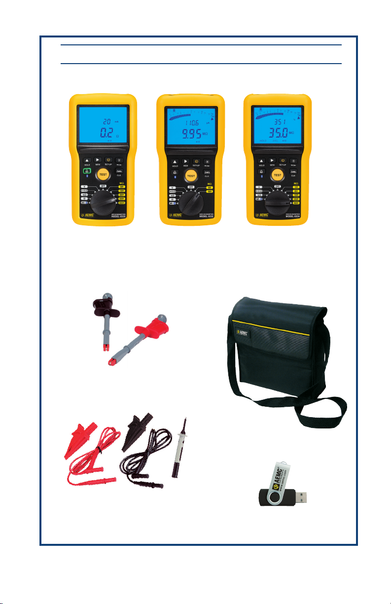
1
Input terminals
2
3
4
5
Blue backlit LCD
Function keys
TEST button to start insulation measurements
Rotary switch to choose the function or to turn the instrument OFF.
The table below lists the functions available for each model instrument.
Functions
Model 6526 Model 6532 Model 6534
Insulation test voltages 50, 100, 250,
500, and
1000V
Insulation resistance 10kΩ to
200GΩ
PI and DAR ratios calculation
Continuity measurement
Resistance measurement
Programmable alarms
Frequency measurement
Capacitance measurement
Distance measurement
Data storage
Bluetooth communication
50 and 100V
10kΩ to
20GΩ
10, 25, 100,
250, and 500V
2kΩ to 50GΩ
Page 6
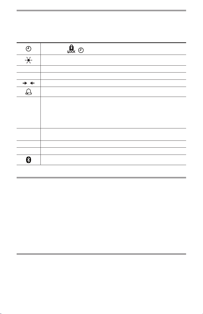
Function Keys
0
In general, each key has two functions. One is marked on the key, and is enabled
via a short press. The second function is marked under the key, and is enabled by a
long (>2 seconds) press.
Selects the , , PI, and DAR functions.
Toggles backlighting ON and OFF.
HOLD Freezes/unfreezes the displayed measurement on the LCD.
SET-UP Accesses the instrument’s setup parameters and information.
Applies lead compensation for use in continuity testing.
Activates/deactivates alarms.
The and ► keys allow you to:
• Select the displayed information and program the durations of
and ►
∆Rel
MEM Records measurements.
CLR Erase recorded measurements.
insulation measurements.
• Choose the continuity test current.
• Program the alarm thresholds.
Sets the present measurement as a “zero reference” to which future
measurements are compared.
Enable Bluetooth wireless communication.
Installing Batteries
1. Disconnect any attached leads or accessories from the instrument and turn the
rotary switch to OFF.
2. Use a tool or a coin to turn the quarter-turn screw of the battery compartment
cover.
3. Remove the battery compartment cover.
4. Remove the batteries from the compartment.
5. Place the new batteries in the compartment, ensuring that each battery’s polarity is correct.
6. Put the battery cover in place and screw the quarter-turn screw back in.
Installing DataView
1. Insert the DataView thumb drive into an available USB port (wait for driver to be
installed).
2. If Autorun is enabled, an AutoPlay window appears on your screen. Click “Open
folder to view les” to display the DataView folder. If Autorun is not enabled or
allowed, use Windows Explorer to locate and open the USB drive labeled “DataView.”
®
Page 7

3. When the DataView folder is open, nd the le Setup.exe and double-click it to
run the installation program.
4. The DataView setup screen appears. In the upper left section of the screen,
choose the language version you want to install. Then select DataView in the
Options list and click Install.
5. The InstallShield Wizard welcome screen appears. The InstallShield Wizard
leads you through the installation process. As you complete these screens, be
sure to click Megohmmeter Logger when prompted to select the Control Panels
to install.
When you have completed all screens, click Finish to leave the InstallShield
6.
Wizard. Then close the DataView Setup screen. The DataView folder now
appears on your computer desktop, containing the Megohmmeter Control Panel
icon.
Connecting to the Computer
1. Set the rotary switch to MR .
2. Press the key for >2 seconds. The icon appears on the LCD, indicating
Bluetooth is enabled on the instrument.
3. Open the Bluetooth Devices dialog on your computer to pair the instrument with
your computer. Dierent operating systems have dierent steps for opening this
dialog, so consult your computer’s documentation for instructions.
4. Once the dialog is displayed, click Add a Device. A dialog box appears listing
the locally available Bluetooth devices. There may be several devices of varying
types listed, depending on the location of your computer.
5. Find the instrument’s Bluetooth name, and click it.
6. You are prompted to enter a pairing code; enter 1111.
7. After you enter the code, click Next. A screen appears informing you that the
instrument has been successfully connected with the computer. Click Close to
exit the screen.
8. Open the Megohmmeter Control Panel. In the menu bar at the top of the screen,
select Help. In the drop-down menu that appears, click the option Help Topics.
This opens the Megohmmeter Control Panel Help system.
9. Use the Contents window in the Help system to locate and open the topic “Connecting to an Instrument.” This topic provides instructions explaining how to
connect your instrument to the computer.
10. After the instrument is successfully connected, consult the Control Panel Help
system for instructions about viewing real-time data, downloading and viewing
recorded sessions, creating DataView reports from the downloaded data, and
conguring the instrument through the Control Panel.
Page 8

Recording Data
Recording a measurement
Press the MEM key for >2 seconds. The measurement is stored in the rst available
location in the instrument’s memory. The saved recording includes all information
associated with the measurement, including voltage, current, duration of tests, T1
and T2 (for PI and DAR), and any other applicable data for the test type. The recording also includes a bar graph indicating how much available memory remains in the
instrument.
Viewing Stored Recordings
1. Set the rotary switch to MR.
2. The instrument displays the last recording stored in the instrument. The
secondary (top) display indicates the memory location; while the main display
indicates the measured value. To see other stored measurements, press the
key. The record number is decremented and the corresponding measurement is displayed.
3. To scroll rapidly through the recorded measurements, keep the key
pressed.
4. To select a specic recording, use the ► key to change the recording number.
5. Once you select the recording number, you can see all information associated
with the measurement. Press the MEM key for >2 seconds, then use the
key to scroll the information.
6. When nished viewing recordings, press MEM for >2 seconds.
Deleting Recordings
To delete a single recording:
1. Set the rotary switch to MR.
2. Use the and ► keys to select the number of the recording to be deleted.
3. Press the CLR key for >2 seconds. The record number blinks and the LCD
displays the letters CLR.
4. Press the MEM key for >2 seconds to conrm the deletion. To cancel, press
the CLR key for >2 seconds.
To delete all stored recordings:
1. Set the rotary switch to MR.
2. Press the CLR key for >2 seconds.
3. Press the key; the record number is replaced by ALL.
4. To cancel, press the CLR key for >2 seconds. Otherwise, press the MEM key
for >2 seconds to conrm the deletion.
5. The instrument displays a message indicating the memory is empty.
Page 9

Repair and Calibration
To ensure that your instrument meets factory specications, we recommend that it
be scheduled back to our factory Service Center at one-year intervals for recalibration, or as required by other standards or internal procedures.
For instrument repair and calibration:
You must contact our Service Center for a Customer Service Authorization Number
(CSA#). This will ensure that when your instrument arrives, it will be tracked and
processed promptly. Please write the CSA# on the outside of the shipping container.
If the instrument is returned for calibration, please specify whether you want a stan-
dard calibration, or a calibration traceable to N.I.S.T. (includes calibration certicate
plus recorded calibration data).
Ship To: Chauvin Arnoux®, Inc. d.b.a. AEMC® Instruments
15 Faraday Drive
Dover, NH 03820 USA
Phone: (800) 945-2362 (Ext. 360)
(603) 749-6434 (Ext. 360)
Fax: (603) 742-2346 or (603) 749-6309
E-mail: repair@aemc.com
(Or contact your authorized distributor.)
Costs for repair, standard calibration, and calibration traceable to N.I.S.T. are
available.
NOTE: You must obtain a CSA# before returning any instrument.
Technical and Sales Assistance
If you are experiencing any technical problems, or require any assistance with
the proper operation or application of your instrument, please call, fax or e-mail our
technical support team:
Contact: Chauvin Arnoux®, Inc. d.b.a. AEMC® Instruments
Phone: (800) 945-2362 (Ext. 351)
(603) 749-6434 (Ext. 351)
Fax: (603) 742-2346
E-mail: techsupport@aemc.com
Page 10

Limited Warranty
The Models 6526, 6532 and 6534 are warranted to the owner for a period of
two years from the date of original purchase against defects in manufacture.
This limited warranty is given by AEMC® Instruments, not by the distributor from
whom it was purchased. This warranty is void if the unit has been tampered
with, abused or if the defect is related to service not performed by AEMC®
Instruments.
Full warranty coverage and registration is available on our website:
www.aemc.com.
Please print the online Warranty Coverage Information for your records.
®
What AEMC
Instruments will do: If a malfunction occurs within the
warranty period, you may return the instrument to us for repair, provided
we have your warranty registration on file or a proof of purchase. AEMC®
Instruments will, at its option, repair or replace the faulty material.
Warranty Repairs
What you must do to return an Instrument for Warranty Repair:
First, request a Customer Service Authorization Number (CSA#) by phone or
e-mail from our Service Department, then return the instrument along with the
signed CSA Form. Please write the CSA# on the outside of the shipping container. Return the instrument, shipment pre-paid to:
Ship To:
Chauvin Arnoux®, Inc. d.b.a. AEMC® Instruments
15FaradayDrive•Dover,NH03820USA
Phone: (800)945-2362or(603)749-6434(Ext.360)
E-mail: repair@aemc.com
Caution: To protect yourself against in-transit loss, we recommend you insure
your returned material.
NOTE: You must obtain a CSA# before returning any instrument.
Page 11

Page 12

®
CHAUVIN ARNOUX GROUP
0
1/18
99-MAN100434v4
Chauvin Arnoux®, Inc. d.b.a. AEMC® Instruments
15FaradayDrive•Dover,NH03820USA
Phone:(603)749-6434•Fax:(603)742-2346
www.aemc.com
 Loading...