

Page 1
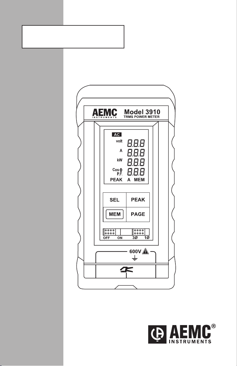
TRUE RMS POWER METER
3 910
E N G L I S H
User Manual
Page 2

Owner’s Record
The serial number for the Model 3910 is located inside the battery compartment of the instrument. Please record this number and purchase date
for your records.
TRMS POWER METER MODEL 3910
CATALOG #: 2111.27
SERIAL #: _______________________________________________
PURCHASE DATE: ________________________________________
DISTRIBUTOR: ___________________________________________
Page 3

Table of Contents
1. INTRODUCTION ............................................................................... 2
1.1 International Electrical Symbols ................................................3
1.2 Receiving Your Shipment ..........................................................3
1.3 Ordering Information .................................................................3
1.3.1 Accessories and Replacement Parts ............................3
2. PRODUCT FEATURES ...................................................................... 4
2.1 Description ................................................................................4
2.2 Control Features .......................................................................5
2.3 Display Features .......................................................................7
2.4 Button Functions ......................................................................7
2.4.1 PEAK Button .................................................................7
2.4.2 Memory Button .............................................................8
3. SPECIFICATIONS............................................................................. 9
3.1 ElectricalSpecications ............................................................9
3.2 MechanicalSpecications ......................................................10
3.3 SafetySpecications ..............................................................11
4. OPERATION .................................................................................. 12
4.1 Single-Phase Networks ..........................................................12
4.2 Balanced Three-Phase Networks ...........................................13
4.3 Three-Phase, Four-Wire Networks .........................................14
4.4 Using as a Voltmeter ...............................................................15
4.5 Using as an Ammeter .............................................................16
4.6 Measurements: Review of Formulas Used .............................17
5. MAINTENANCE ............................................................................. 18
5.1 Warning...................................................................................18
5.2 Battery Replacement ..............................................................18
5.3 Cleaning ..................................................................................18
Repair and Calibration ...........................................................................19
Technical and Sales Assistance ............................................................19
Limited Warranty ...................................................................................20
Warranty Repairs ...................................................................................20
Page 4

CHAPTER 1
INTRODUCTION
WARNING
These safety warnings are provided to ensure the safety of
personnel and proper operation of the instrument.
• Read this instruction manual completely before attempting
to use or service this instrument and follow all the safety
information.
• Use caution on any circuit: Potentially high voltages and
currents may be present and may pose a shock hazard.
• The instrument must not be operated beyond its specied
operating range.
• Safety is the responsibility of the operator.
• Never open the back of the instrument while connected to
any circuit or input.
• Always make connections from the instrument to the circuit
under test.
• Always inspect the instrument and accessory leads for serviceability prior to use, and replace defective parts immediately.
• Do not use the meter or any test leads, connectors, probes or
clips if they look damaged.
• Never use the Model 3910 on electrical conductors rated
above 600V.
• On the current probe input, only use the current probe(s)
supplied with the instrument.
• Never use the Model 3910 without its rubber holster.
2
TRMS Power Meter Model 3910
Page 5
1.1 International Electrical Symbols
Thissymbolsigniesthattheinstrumentisprotectedbydoubleor
reinforced insulation. Use only specied replacement parts when
servicing the instrument.
This symbol on the instrument indicates a WARNING and that
the operator must refer to the user manual for instructions before
operating the instrument. In this manual, the symbol preceding
instructions indicates that if the instructions are not followed, bodily
injury, installation/sample and product damage may result.
Risk of electric shock. The voltage at the parts marked with this
symbol may be dangerous.
1.2 Receiving Your Shipment
Upon receiving your shipment, make sure that the contents are consistent
with the packing list. Notify your distributor of any missing items. If the
equipmentappearstobedamaged,leaclaimimmediatelywiththecarrier and notify your distributor at once, giving a detailed description of any
damage. Save the damaged packing container to substantiate your claim.
Do not use an instrument that appears to be damaged.
1.3 Ordering Information
TRMS Power Meter Model 3910........................................ Cat. #2111.27
Includes 3910 power meter, shock-proof safety holster, 500AAC clamp-on current probe, two
5 ft (1.5m) leads, two test probes, two probe grips, batteries (not installed), user manual and
hard carrying case.
1.3.1 Accessories and Replacement Parts
Probe Adaptor......................................................................Cat. #2118.34
Clamp-on Current Probe Model SR652 (1000AAC) ............. Cat. #2113.46
Order Accessories and Replacement Parts Directly Online
Check our Storefront at www.aemc.com for availability
TRMS Power Meter Model 3910
3
Page 6

CHAPTER 2
PRODUCT FEATURES
2.1 Description
The True RMS Power Meter Model 3910 is designed for today’s electrical
environments. Operation is simple. There are no programming requirements or menus, just four push-buttons for direct access. The Model 3910
is auto-ranging and ensures the best range for measurements.
Troubleshooting and measuring power is done simply by connecting two
voltage leads and clamping on the current probe. The Model 3910 is
easier to operate than most DMMs and may even replace your multimeter
for individual voltage or current measurements.
Small and compact in its protective holster, the Model 3910 provides seven
essential power measurement values. Four measurements are displayed
at a time on its extra large multi-display LCD.
The Model 3910 performs current and voltage measurements in True
RMS, and provides immediate readings of power factor (PF), active power
(kW), reactive power (kVar), apparent power (kVA) and frequency (Hz).
The Model 3910 displays Vrms,Arms, kW and PF on the rst screen;
pressing and holding the PAGE button gives access to kVar, kVA and Hz
on a second screen.
ThePeakfunctionallowsselectionofaspecicparameter(A,VorW)for
peak measurement, and also displays the associated values at the particular peak (for example, the Model 3910 displays the actual V, kW, PF,
kVar, kVA and Hz values when Apeak is selected).
The unique memory function permits not only storing the measurements
at any time, but also comparing subsequent readings by displaying the difference between the stored values and the new readings. This is helpful in
analyzing and measuring the impact of loads being turned on and off.
A selector switch on the front panel selects power measurements for
single-phase or balanced three-phase, three-wire systems.
4
TRMS Power Meter Model 3910
Page 7
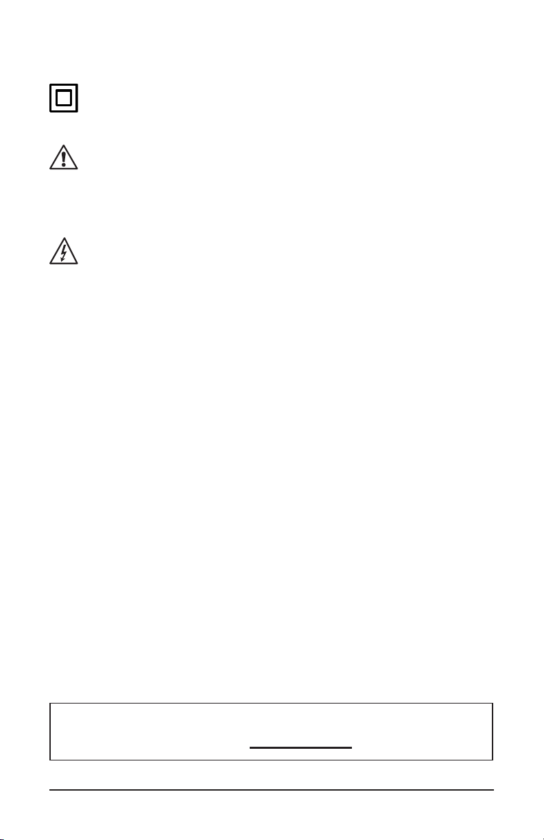
2.2 Control Features
1
2
3
5
6
7
8
9
4
TRMS Power Meter Model 3910
5
Page 8

1. SEL Button
Selects the parameter (A, W, V) whose peak is to be measured.
2. MEM Button
Accesses two functions:
• Memory
• Measurements of differences in voltage, current and active power
between stored values and subsequent readings.
3. ON/OFF Switch
Turns the instrument ON or OFF. The Model 3910 takes a few seconds to power up when turned “ON”.
4. Clamp Input
FRB socket for connecting the clamp-on current probe. Use only
speciedcurrentprobes,whichhaveavoltageoutput(1mVAC/AAC).
5. Display
LCD (40x50mm), displays the seven measurements on two pages.
NOTE: A beep sounds when the PAGE, PEAK, SEL or MEM button
is pressed.
6. PEAK Button
Selects “PEAK” measurement mode.
7. PAGE Button
Displays Vrms, Arms, W, PF (or Cos Φ)onpage1automatically;
pressing PAGE gives access to Var, VA and Hz on page 2.
8. 1Ø / 3Ø
Selects the type of network to be tested.
• 1Ø: single-phase
• 3Ø: balanced three-phase, three-wire
9. Voltage Inputs
Two safety input terminals (4mm) for lead connection. Voltage measurement may be made up to 600VAC/DC.
6
TRMS Power Meter Model 3910
Page 9
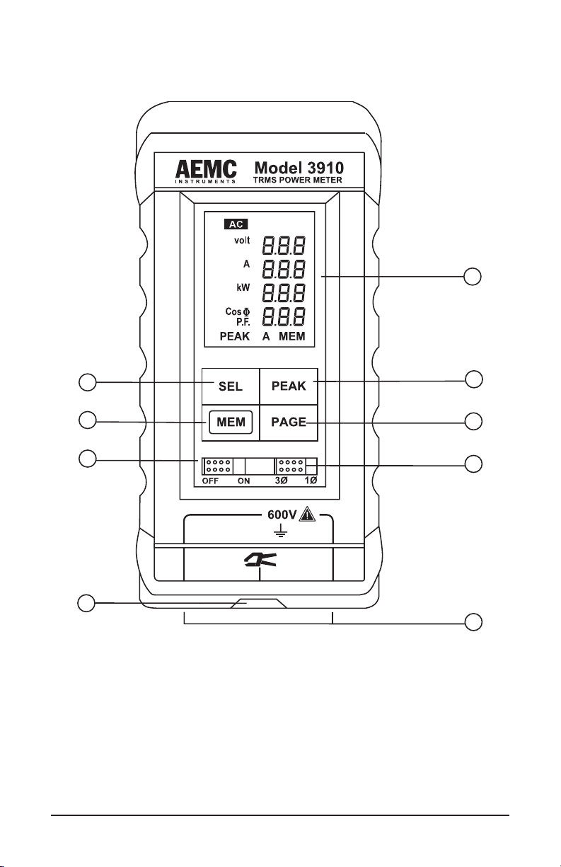
2.3 Display Features
When the Model 3910 is switched ON, page 1 is displayed automatically:
• RMS voltage (V)
• RMS current (A)
• Active power (W)
• Power factor (pF) (or Cos Φ)
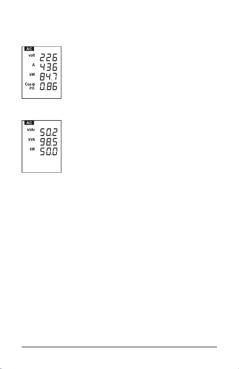
Hold down the PAGE button to display page 2:
• Reactive power (Var)
• Apparent power (VA)
• Frequency (Hz)
To return to page 1, release the PAGE button
2.4 Button Functions
2.4.1 PEAK Button
When this button is activated, PEAK values of a measurement can be
displayed.
To activate the PEAK mode, press the PEAK button once. The Model
3910 changes initially to peak current measurements and “PEAK A” is
displayed.
Press the SEL button to choose the desired parameter (A, W, V). The SEL
button can only be used after the PEAK button has been activated.
NOTE: The peak measurement is:
• the maximum value for the current (A)
• the maximum value for the active power (W)
• the minimum value for the voltage (V)
TRMS Power Meter Model 3910
7
Page 10

The Model 3910 stores all the measurements present when peak is
selected.Therstfourmeasurements(V,A,W,PF)aredisplayedonpage
1 and the following three measurements (Var, VA, Hz) on page 2 (press
thePAGEbutton).Forexample,youcanndthevoltage,thepower,etc.,
at the moment when current is at a peak.
In PEAK mode, the typical acquisition time is 400ms. Each new peak is
taken into account as long as the PEAK button is activated. To exit PEAK
mode, press the PEAK button.
2.4.2 Memory Button
This button has two functions:
• First Function - Memory
To store page 1 of the display, press the MEM button
once. “MEM” will show on the display.
Voltage, current, active power and power factor are
stored.
• Second Function - Differential Measurements
Once the values are memorized (MEM is displayed), press the PAGE
button. Page 2 will display the differences between the values in memory
and the values that the instrument continues to measure.
Measurements of differences in voltage, current
and active power.
NOTE: The power factor is no longer displayed.
If the difference between measurements is a negative value, a minus “-” sign is displayed.
To exit memory mode, press the MEM button again.
8
TRMS Power Meter Model 3910
Page 11

CHAPTER 3
SPECIFICATIONS
Reference Conditions: Temperature 23°C ± 5K, 45 to 75% RH; battery voltage 6V; conduc-
tor centered in the probe jaws; DC magnetic eld; earth’s eld; no external AC magnetic eld;
no external electrical eld; sine wave 45 to 65Hz. In Peak, basic accuracy is based on 1 ms
samples and on a signal from 10 to 500Hz.
3.1 Electrical Specifications
CURRENT (TRMS)
Input Range: 1 to 500ARMS
Typical Accuracy (and Phase Shift) with 500A Current Probe MD313:
25A: 5% of Reading (4°)
100A: 2% of Reading (2°)
500A: 2% of Reading (1.5°)
Typical Accuracy (and Phase Shift) with 1000A Current Probe SD652:
50A: ± 0.9% of Reading (1.5°)
200A: ± 0.5% of Reading (0.5°)
1000A: ± 0.5% of Reading (0.5°)
Resolution:
1 to 9.99A: 10mA
10 to 99.9A: 100mA
100 to 500A: 1A
VOLTAGE (TRMS)
Input Range: 0 to 600VRMS
Accuracy:
1 to 99.9V: 0.5% ± 0.6V
100 to 600V: 0.3% ± 2V
Resolution:
0 to 99.9V: 0.1V, 100 to 600V: 1V
TRMS Power Meter Model 3910
9
Page 12

FREQUENCY
Input Range (from voltage input):
30 to 100Hz
101 to 999Hz
Accuracy:
30 to 100Hz: 0.03% of Reading ± 0.1Hz
101 to 999Hz: 0.5% of Reading ± 1Hz
POWER FACTOR
Range: -0.00 (Lag) to +0.00 (Lead)
Accuracy: Sum of the V and A accuracy plus the probe phase shift
ACTIVE POWER
Range: 30W to 300kW (600kW with SR652 probe)
Accuracy: Sum of the V and A accuracy
REACTIVE POWER
Range: 0 to 300kVar (600kVar with SR652 probe)
Accuracy:
APPARENT POWER
Range: 0 to 300kVA (600kVA with SR652 probe)
Sum of V and A accuracy @ Sin Φ = 1 plus the probe phase shift
Accuracy: Sum of the V and A accuracy
3.2 Mechanical Specifications
Display: 1.58 x 1.97" (40 x 50mm) multi-display LCD
Power Supply: Four 1.5V AA alkaline batteries
Low Battery Indicator: “BAT” on display
Battery Life: 50 hours approx, continuous use
10
TRMS Power Meter Model 3910
Page 13

Dimensions:
3.2 x 6.9 x 1.3" (80 x 175 x 32mm) - without holster
3.5 x 7.7 x 2.1" (90 x 195 x 54mm) - with holster
Weight (with battery):
15 oz (400g) - without holster
17.6 oz (500g) - with holster
Supplied 500A current probe:
Accommodates two 500 MCM or one 750 MCM
3.3 Safety Specifications
Protection Level: EN 61010, Class II
Protection Index: IP40 per IED 529
Max. Voltage Overload: 825Vrms, 1170Vpeak
TRMS Power Meter Model 3910
11
Page 14

CHAPTER 4
OPERATION
4.1 Single-Phase Networks
WARNING: Maximum voltage rating 600V
• Set the selector switch to the 1Ø position.
• Connect the Model 3910 as shown in the diagram, with phase connected to the right terminal and the probe on phase.
NOTE: Only clamp the current probe around one conductor.
The arrow on the current probe should always point towards the load for
correct polarity indication during power measurements.
12
TRMS Power Meter Model 3910
Page 15

4.2 Balanced Three-Phase Networks
WARNING: Maximum voltage rating 600V
• Set the selector switch to the 3Ø position.
• Connect the Model 3910 as shown in the diagram. Note that the current probe is clamped onto the conductor that is not connected to a
voltage input.
The Model 3910 will automatically display the system power on balanced
three-phase, three-wire circuits (two wattmeter method).
TRMS Power Meter Model 3910
13
Page 16
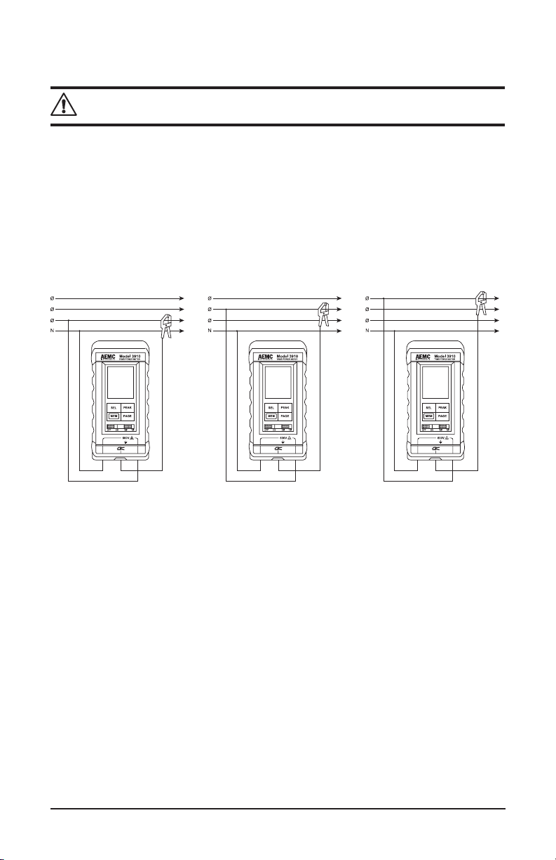
4.3 Three-Phase, Four-Wire Networks
WARNING: Maximum voltage rating 600V
• Set the selector switch to the 1Ø position.
• Connect the Model 3910 as shown for single-phase (phase-to-neutral)
and measure on each phase.
• Add all three readings for system total.
Total W = W1 + W2 + W
14
3
TRMS Power Meter Model 3910
Page 17
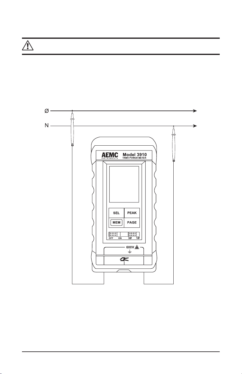
4.4 Using as a Voltmeter
WARNING: Maximum voltage rating 600V
• Plug voltage leads into the safety input terminals.
• The selector switch may be set at either 1Ø or 3Ø position.
• Connect the Model 3910 as shown in the diagram below.
Note: The Model 3910 may also measure DC volts. DC will be displayed
on the LCD.
TRMS Power Meter Model 3910
15
Page 18

4.5 Using as an Ammeter
WARNING: Maximum voltage rating 600V
• Connect the current probe to the FRB socket.
• The selector switch may be set at either 1Ø or 3Ø position.
• Connect the Model 3910 as shown in the diagram.
• Only use the supplied current probes (MD313 or optional SR652)
16
TRMS Power Meter Model 3910
Page 19

4.6 Measurements: Review of Formulas Used
RMS Voltage:
Vrms =
∑
1
n
2
n
V
1
n
RMS Current:
Irms =
∑
1
n
2
n
I
1
n
W
VA
Active Power: W =
∑
1
n
Vn.In
VA
1
n
Apparent Power: VA = Vrms x Irms
Power Factor: PF =
Reactive Power: Var =
2
W
2
TRMS Power Meter Model 3910
17
Page 20

CHAPTER 5
MAINTENANCE
5.1 Warning
Use only factory specied replacement parts. AEMC® will not be held
responsible for any accident, incident, or malfunction following a repair
done other than by its service center or by an approved repair center.
• Do not allow water or other foreign substances into the instrument.
• Disconnect the unit from all circuits and test cables before opening the
case.
5.2 Battery Replacement
The TRMS Power Meter Model 3910 is powered by four 1.5V “AA” alkaline batteries. When the battery indicator shows that the batteries are low
(“BAT” appears on the LCD), the batteries should be replaced.
• Unplug the leads and the clamp from the instrument.
• Remove the shock-proof case.
• Lift the fold-away stand and pry off the battery compartment cover with
a small screwdriver.
• Insert four new 1.5V “AA” alkaline batteries, being sure to observe the
polarity shown in the battery housing.
• Replace the cover of the battery compartment and the shock-proof
case before use.
5.3 Cleaning
Disconnect the instrument from any power source. Use a soft cloth slightly
moistened with soapy water. Rinse with a damp cloth and quickly dry with
a dry cloth or forced dry air. Do not use any abrasives or solvents.
18
TRMS Power Meter Model 3910
Page 21

Repair and Calibration
Toensurethatyourinstrumentmeetsfactoryspecications,werecommend
that it be scheduled back to our factory Service Center at one-year intervals
for recalibration, or as required by other standards or internal procedures.
For instrument repair and calibration:
You must contact our Service Center for a Customer Service Authorization
Number (CSA#). This will ensure that when your instrument arrives, it will be
tracked and processed promptly. Please write the CSA# on the outside of the
shipping container. If the instrument is returned for calibration, we need to
know if you want a standard calibration, or a calibration traceable to N.I.S.T.
(Includescalibrationcerticateplusrecordedcalibrationdata).
Ship To: Chauvin Arnoux®, Inc. d.b.a. AEMC® Instruments
15 Faraday Drive
Dover, NH 03820 USA
Phone: (800) 945-2362 (Ext. 360)
(603) 749-6434 (Ext. 360)
Fax: (603) 742-2346 or (603) 749-6309
E-mail: repair@aemc.com
(Or contact your authorized distributor)
Costs for repair, standard calibration, and calibration traceable to N.I.S.T. are
available.
NOTE: You must obtain a CSA# before returning any instrument.
Technical and Sales Assistance
If you are experiencing any technical problems, or require any assistance
with the proper operation or application of your instrument, please call, fax or
e-mail our technical support team:
Contact:
TRMS Power Meter Model 3910
Chauvin Arnoux®, Inc. d.b.a. AEMC® Instruments
Phone: (800) 945-2362 (Ext. 351)
(603) 749-6434 (Ext. 351)
Fax: (603) 742-2346
E-mail: techsupport@aemc.com
19
Page 22

Limited Warranty
The Model 3910 is warranted to the owner for a period of 2 years
of original purchase against defects in manufacture. This limited war-
date
ranty is given by AEMC®Instruments, not by the distributor from whom it was
pur-chased. This warranty is void if the unit has been tampered with, abused
or if the defect is related to service not performed by AEMC® Instruments.
For full and detailed warranty coverage, please read the Warranty
Coverage Information, which is attached to the Warranty Registration
Card (if enclosed) or is available at www.aemc.com. Please keep the
Warranty Coverage Information with your records.
What AEMC® Instruments will do:
If a malfunction occurs within the warranty period, you may return the instrument
tous for repair, providedwehave your warrantyregistrationinformation on
file or a proof of purchase. AEMC® Instruments will, at its option, repair or
replace the faulty material.
from the
REGISTER ONLINE AT:
www.aemc.com
Warranty Repairs
What you must do to return an Instrument for Warranty Repair:
First, request a Customer Service Authorization Number (CSA#) by phone
or by fax from our Service Department (see address below), then return the
instrument along with the signed CSA Form. Please write the CSA# on the
outside of the shipping container. Return the instrument, postage or shipment
pre-paid to:
Ship To: Chauvin Arnoux®, Inc. d.b.a. AEMC® Instruments
15 Faraday Drive • Dover, NH 03820 USA
Phone: (800) 945-2362 (Ext. 360)
(603) 749-6434 (Ext. 360)
Fax: (603) 742-2346 or (603) 749-6309
E-mail: repair@aemc.com
Caution:
your returned material.
NOTE: You must obtain a CSA# before returning any instrument.
20
To protect yourself against in-transit loss, we recommend you insure
TRMS Power Meter Model 3910
Page 23

Page 24

02/18
99-MAN 100072 v3
15 Faraday Drive • Dover, NH 03820 USA • Phone: (603) 749-6434 • Fax: (603) 742-2346
Chauvin Arnoux®, Inc. d.b.a. AEMC® Instruments
www.aemc.com
 Loading...