

Page 1
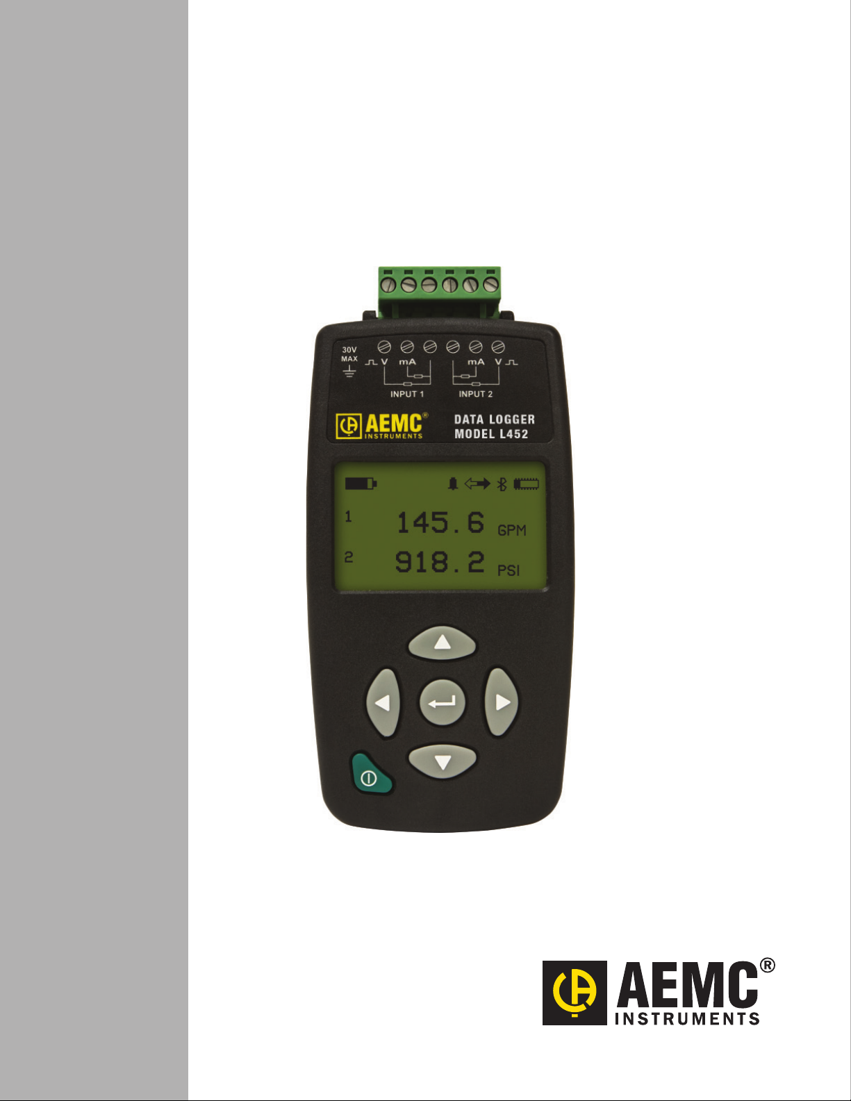
DATA LOGGER
MODEL L452
ENGLISH
User Manual
Page 2

Statement of Compliance
Chauvin Arnoux®, Inc. d.b.a. AEMC® Instruments certies
that this instrument has been calibrated using standards and
instruments traceable to international standards.
We guarantee that at the time of shipping your instrument has
met its published specications.
An NIST traceable certicate may be requested at the time of
purchase, or obtained by returning the instrument to our repair
and calibration facility, for a nominal charge.
The recommended calibration interval for this instrument is
12 months and begins on the date of receipt by the customer.
For recalibration, please use our calibration services.
Refer to our repair and calibration section at www.aemc.com.
Serial #: ______________________________
Catalog #: 2153.51
Model #: L452
Please ll in the appropriate date as indicated:
Date Received: ____________________________
Date Calibration Due: _______________________
Chauvin Arnoux®, Inc.
d.b.a AEMC® Instruments
www.aemc.com
Page 3

Copyright © Chauvin Arnoux®, Inc. d.b.a. AEMC® Instruments. All rights reserved.
No part of this documentation may be reproduced in any form or by any means (including electronic storage and retrieval or translation
into any other language) without prior agreement and written consent from Chauvin Arnoux®, Inc., as governed by United States and
International copyright laws.
Chauvin Arnoux®, Inc. d.b.a. AEMC® Instruments
15 Faraday Drive • Dover, NH 03820 USA
Tel: (800) 945-2362 or (603) 749-6434 • Fax: (603) 742-2346
This documentation is provided “as is,” without warranty of any kind, express, implied, or otherwise. Chauvin Arnoux®, Inc. has made
every reasonable eort to ensure that this documentation is accurate; but does not warrant the accuracy or completeness of the text,
graphics, or other information contained in this documentation. Chauvin Arnoux®, Inc. shall not be liable for any damages, special, indirect,
incidental, or inconsequential; including (but not limited to) physical, emotional or monetary damages due to lost revenues or lost prots
that may result from the use of this documentation, whether or not the user of the documentation has been advised of the possibility of
such damages.
Chauvin Arnoux®, Inc, AEMC®, DataView®, AmpFlex®, MiniFlex® and PowerPad® are registered trademarks of AEMC® Instruments.
Page 4
Before using your Data Logger Model L452 for the rst time, please take a moment to review the following.
Signies that the instrument is protected by double or reinforced insulation.
CAUTION - Risk of Danger! Indicates a WARNING that the operator must refer to the User Manual for instructions before
operating the instrument in all cases where this symbol is marked.
Risk of electric shock. The voltage at the parts marked with this symbol may be dangerous.
Bluetooth enabled.
Ground/Earth.
Important instructions to read and understand completely.
Important information to acknowledge.
Battery.
Fuse.
USB socket.
Compliance with the Low Voltage & Electromagnetic Compatibility European directives (73/23/CEE & 89/336/CEE)
In the European Union, this product is subject to a separate collection system for recycling electrical and electronic components in accordance with directive WEEE 2002/96/EC.
The product has been declared recyclable.
Denition of Measurement Categories (CAT)
■ CAT II Measurements taken on circuits directly connected to low-voltage installations.
Example: power supply to domestic electrical appliances and portable tools.
■ CAT III Measurements taken on building installations.
Example:distributionpanel,circuit-breakers,machinesorxedindustrialdevices.
■ CAT IV Measurements taken at the source of low-voltage installations.
Example:powerfeeders,countersandprotectiondevices.
PRECAUTIONS FOR USE
These warnings are provided to ensure the safety of personnel. Please read and comply with these precautions.
■ Do not use this instrument in an explosive atmosphere or in the presence of ammable gases.
■ Observe the maximum voltages and intensities assigned between terminals and ground/earth.
■ Do not use the instrument if it appears damaged, incomplete, or improperly closed.
■ Before each use, check the condition of the insulation of cables, case, and accessories. Anything which appears damaged
(even partially) must be reported for repair or scrapping.
■ Use only leads and accessories that meet instrument specications.
■ Observe the environmental specications for the use of this instrument, as specied in § 7 of this User Manual.
■ Do not modify the instrument. Use only original replacement parts. Repairs or adjustments must be performed by authorized
personnel.
■ Replace the batteries when they can no longer hold a charge. Disconnect all cables from the instrument before opening the
access door to the batteries, as explained in § 8.1.3.
■ Use protective equipment as required by the environment in which you are operating this instrument.
■ When handling probes, probe tips, current sensors, signal conditioners, and alligator clips, keep ngers behind the guard.
Page 5

TABLE OF CONTENTS
1. INTRODUCTION ............................................................................................................................... 6
1.1 Receiving Your Shipment ........................................................................................................................................6
1.2 Ordering Information ...............................................................................................................................................6
1.2.1 Accessories .................................................................................................................................................. 6
1.2.2 Replacement Parts .......................................................................................................................................6
2. PRODUCT FEATURES ..................................................................................................................... 7
2.1 Model L452 Features ..............................................................................................................................................7
2.2 Electrical Power .......................................................................................................................................................8
2.3 Using the Model L452 User Interface ......................................................................................................................8
2.3.1 Model L452 Screens ....................................................................................................................................8
2.3.2 Front Panel Buttons ...................................................................................................................................10
2.3.3 Entering Text .............................................................................................................................................. 11
3. CONFIGURATION .......................................................................................................................... 12
3.1 Instrument Conguration .......................................................................................................................................12
3.1.1 Choosing the Language for the Interface ................................................................................................... 13
3.1.2 Setting the Instrument Date and Time ........................................................................................................13
3.1.3 Enabling and Conguring Bluetooth...........................................................................................................14
3.2 Channel Conguration ...........................................................................................................................................15
3.2.1 Enabling and Disabling Channels ..............................................................................................................16
3.2.2 Selecting the Input Type ............................................................................................................................. 16
3.2.2.1 Analog ................................................................................................................................................ 16
3.2.2.2 Pulse Count........................................................................................................................................16
3.2.2.3 Event ..................................................................................................................................................16
3.2.3 Dening Units .............................................................................................................................................17
3.2.4 Selecting Low and High Scaling Factors .................................................................................................... 17
3.2.5 Enabling and Dening Alarm Triggers ........................................................................................................19
3.2.6 Dening Equivalence (Pulse Input Only) .................................................................................................... 20
3.2.7 Selecting Event Trigger (Event Input Only) ................................................................................................ 20
3.3 Restoring Conguration to the Original Settings ...................................................................................................21
3.4 Viewing Instrument Information .............................................................................................................................21
3.4.1 Model, Serial Number, and Firmware Revision .......................................................................................... 22
3.4.2 Name and Location Screen ........................................................................................................................22
3.4.3 Recording Session Screen .........................................................................................................................22
3.4.4 Recording Name Screen ............................................................................................................................23
4. CONNECTING TO INPUTS & VIEWING MEASUREMENTS ........................................................ 24
4.1 Connecting Probes, Signal Conditioners, and Sensors .......................................................................................24
4.2 Viewing Measurement Data ..................................................................................................................................25
4.2.1 Analog Measurement Data ......................................................................................................................... 25
4.2.2 Pulse Count Measurement Data ................................................................................................................27
4.2.3 Event Measurement Data ..........................................................................................................................27
Data Logger Model L452
3
Page 6

5. RECORDING DATA ........................................................................................................................ 29
5.1 Recording Session Overview ................................................................................................................................29
5.2 Recording Screens ................................................................................................................................................29
5.3 Conguring a Recording Session ..........................................................................................................................30
5.4 Starting a Recording Session ................................................................................................................................31
5.5 Scheduling a Recording Session ..........................................................................................................................31
5.6 Stopping or Cancelling a Recording Session ........................................................................................................32
6. DATAVIEW
6.1 Installing DataView ................................................................................................................................................34
6.2 The Data Logger Control Panel .............................................................................................................................37
6.3 Connecting the Model L452 to the Computer ........................................................................................................ 37
6.3.1 USB Connection .........................................................................................................................................38
6.3.2 Bluetooth Connection .................................................................................................................................38
® ....................................................................................................................................................................................................................................... 34
7. SPECIFICATIONS .......................................................................................................................... 39
7.1 Reference Conditions ............................................................................................................................................39
7.2 Electrical ................................................................................................................................................................39
7.2.1 Input Types ................................................................................................................................................. 39
7.2.2 Power Supply .............................................................................................................................................39
7.3 Recording and Data Storage .................................................................................................................................40
7.4 Communication .....................................................................................................................................................40
7.5 Mechanical ............................................................................................................................................................40
7.6 Environmental .......................................................................................................................................................40
7.7 Safety ...................................................................................................................................................................40
8. MAINTENANCE AND TROUBLESHOOTING ................................................................................ 41
8.1 Model L452 Maintenance ......................................................................................................................................41
8.1.1 Erasing Memory .........................................................................................................................................41
8.1.2 Upgrading to the Latest Firmware ..............................................................................................................42
8.1.3 Installing and Replacing the Batteries ........................................................................................................ 42
8.1.4 Cleaning the Instrument .............................................................................................................................43
8.2 Troubleshooting the Model L452 ........................................................................................................................... 43
8.2.1 L452 Does Not Turn ON .............................................................................................................................43
8.2.2 L452 Turns ON But Does Not Function ......................................................................................................43
8.2.3 Overload (OL) Icon is Displayed ................................................................................................................44
8.2.4 Cannot Congure the L452 ........................................................................................................................44
8.2.5 Cannot Congure a Recording Session ..................................................................................................... 44
8.2.6 Recording Sessions Do Not Start ..............................................................................................................44
8.2.7 Recording Sessions End Prematurely .......................................................................................................45
8.2.8 Cannot Connect to a Computer .................................................................................................................45
8.2.9 Cannot Turn OFF the Model L452 .............................................................................................................45
4
Data Logger Model L452
Page 7

APPENDIX A. USER INTERFACE SCREENS ................................................................................... 46
A.1 Measurement Data Screens .................................................................................................................................47
A.2 Recording Screens ...............................................................................................................................................48
A.3 Channel 1 and Channel 2 Conguration Screens ................................................................................................. 49
A.4 Instrument Conguration Screens ........................................................................................................................52
A.5 Instrument Information Screens ............................................................................................................................53
Repair and Calibration ...................................................................................................................... 55
Technical and Sales Assistance....................................................................................................... 55
Limited Warranty ............................................................................................................................... 56
Warranty Repairs ............................................................................................................................... 56
Data Logger Model L452
5
Page 8

1. INTRODUCTION
1.1 Receiving Your Shipment
Upon receiving your shipment, make sure that the contents are consistent with the packing list. Notify your distributor of any missing
items. If the equipment appears to be damaged, le a claim immediately with the carrier and notify your distributor at once, giving a
detailed description of any damage. Save the damaged packing container to substantiate your claim.
1.2 Ordering Information
Data Logger Model L452 ...................................................................................................................................................... Cat. #2153.51
Includes Data Logger Model L452, 6 ft USB cable, US 120V Wall-to-USB plug, 6-pin screw terminal block, 2 AA rechargeable NiMH batteries, quick start guide, and a USB stick containing DataView® software and a user manual.
1.2.1 Accessories
Multix (Universal Mounting System) .................................................................................................................................... Cat. #5000.44
Small Carrying Pouch ............................................................................................................................................................ Cat. #2154.71
Hard Carrying Case ................................................................................................................................................................Cat. #2118.09
Wall Mount Holster (gray) ...................................................................................................................................................... Cat. #2138.61
1.2.2 Replacement Parts
Cable – Replacement 6 ft USB.............................................................................................................................................. Cat. #2138.66
Adapter – Replacement US Wall-to-USB plug ..................................................................................................................... Cat. #2153.78
Screw Terminal Block (6-pin) ................................................................................................................................................. Cat. #2153.77
DataView® Software Updates are Available at www.aemc.com
6
Data Logger Model L452
Page 9
2. PRODUCT FEATURES
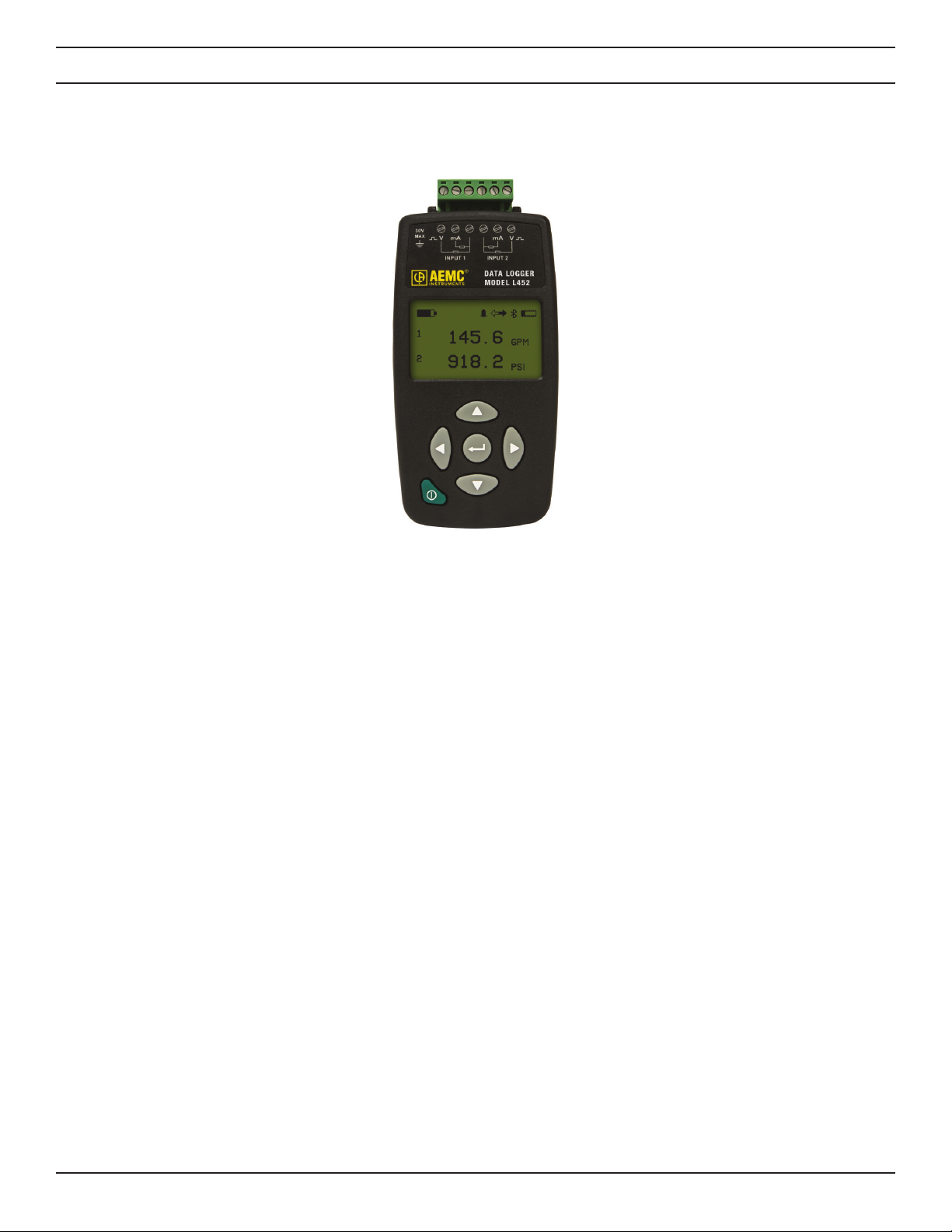
The AEMC Data Logger Model L452 is a two-channel data logger. The instrument is Bluetooth-enabled and records DC voltage, DC
current, pulse count, and event input. Typical applications include process control and measurement, utility metering, and environmental
monitoring.
Figure 1. Data Logger Model L452
2.1 Model L452 Features
The Model L452 combines the functionality of three earlier Simple Logger II products: the Model L322 (4 to 20mA logger), Model L432
(user-selectable ±100mV, ±1V, and ±10V logger), and Model L404 (event logger). Voltage and current measurements can be sampled
from 200ms to 1 minute; sampled quantities can be averaged (mean value) from 200ms to 1 hour and recorded.
Primary features include:
■ Multiple data input types. The Model L452 can log DC voltage, DC current, pulse count, or event data, using either one or
two inputs. Measurements can be performed directly on the instrument through a variety of sources, such as sensors. This
data can be stored in the instrument’s 32MB internal memory.
■ User interface. You can set up the instrument and view measurement data through the front panel LCD screen and input
buttons. The L452 features an on-board interface for navigating measurement data and selecting conguration options.
■ DataView support. The instrument connects to a computer using either Bluetooth or USB. Once connected, recorded data
can be downloaded, analyzed, and formatted into reports using DataView’s Data Logger Control Panel. This Control Panel
also enables you to change settings on the instrument, view real-time measurements, schedule recording sessions, and
perform other conguration tasks.
The Model L452 includes two modes of operation:
■ Local mode provides setup and measurement data display through the instrument’s LCD screen. In Local mode, you can
select conguration settings, start and stop a data recording session on the instrument, and view measurement data.
■ Remote mode controls the L452 from “outside.” You can connect the instrument directly to a computer and then work with it
through the DataView Data Logger Control Panel (see § 6). Remote mode can be enabled automatically (when the instrument
is actively communicating with the computer) or manually by selecting an option in the Control Panel.
Working environments for the Model L452 include factory oors, utilities, and any area being monitored for environmental or process
trends. Users of the Model L452 include utility personnel, factory technicians, environmental monitors, and others. Typical applications
include process measurement, utility metering, monitoring a battery’s charge, and any application involving phenomena recorded over a
period of time.
Data Logger Model L452
7
Page 10

2.2 Electrical Power
The instrument can operate on two sources of power:
■ USB cable connected to an external power source, such as a computer
■ Two internal 1.2V AA rechargeable NiMH batteries
You must insert the batteries into the instrument before use, even when operating on USB power. Consult § 8.1.3, “Installing and Replacing the Batteries,” for instructions about how to do this.
2.3 Using the Model L452 User Interface
Before using the Model L452 for the rst time, you should take a few minutes to familiarize yourself with the instrument’s user interface.
This consists primarily of a set of screens that appear on the L452’s LCD, and the buttons used to navigate these screens, select options,
and enter conguration information. These buttons and screens operate in combination to enable you to view displayed data, select the
congurable parameters, and modify these parameters. The functions performed by the buttons depend on what operational mode (navigation, selection, or edit) the L452 is currently in:
■ Navigation mode is the default state for the user interface. In navigation mode the Up ▲, Down ▼, Left ◄, and Right ►
buttons are used to navigate through the columns and rows of screens.
■ Selection mode is initiated by pressing the Enter button while in navigation mode in any conguration screen. In selection
mode the buttons are used to select a conguration parameter, or an individual value within a multi-value parameter. The
selected user-editable option appears in blinking reversed text (light on dark background).
■ Edit mode is started by pressing the button in selection mode. In edit mode buttons are used to change the value of the
currently selected congurable parameter. When in edit mode, editable elds appear in solid (non-blinking) reversed text.
2.3.1 Model L452 Screens
The screens that appear on the instrument’s 128 x 64 graphical LCD serve as the primary interface through which you interact with the
instrument locally. These screens, in conjunction with the buttons on the front panel, provide the features and functionality that enable the
Model L452 to operate as a standalone instrument.
Screens are organized into six categories:
■ Measurement data screens display the measurement data (including minimum and maximum values) for the two input
channels.
■ Recording screens start, stop, schedule, and congure recording sessions.
■ Channel 1 conguration and Channel 2 conguration screens set a variety of parameters for each channel on the
instrument, including input type, measurement units, scaling, alarms, and related information. (Note that input type must be the
same for both channels.)
■ Instrument conguration screens set general parameters and perform tasks on the instrument, such as setting the display
language, erasing memory, resetting the conguration to default settings, setting date/time, and modifying Bluetooth settings.
■ Instrument information screens are display-only and show current instrument information.
8
Data Logger Model L452
Page 11
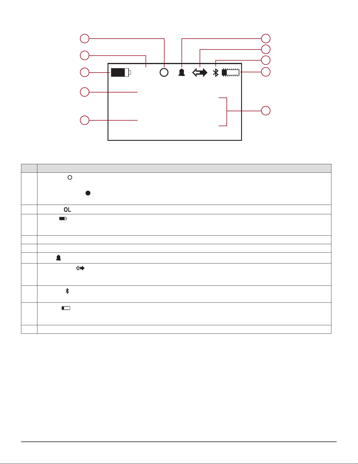
These screens are described in detail in Appendix A. An example of a Model L452 screen is shown in Figure 2:
1 6
7
2
8
3
4
1
OL
24.5
mV
9
10
5
Item Description
Recording indicates the current status of recording activity on the instrument.
1
2
3
4 Measurement data for Channel 1.
5 Measurement data for Channel 2.
6
7
- An empty (unlled) circle (shown above) indicates a recording is scheduled but has not yet started.
- A lled circle indicates a recording is currently in progress.
- If no circle appears, a recording is neither scheduled nor in progress.
Overload indicates that the input is out of range for the selected input type and cannot be displayed.
Battery indicates how much electric charge remains in the Model L452’s two batteries. The lled portion of the icon cor-
responds to the percentage of remaining power. When the batteries are charging, the lled portion repeatedly moves from
the completely discharged level to the completely full level.
Alarm indicates at least one channel is in an alarm condition.
Remote mode indicates that Remote mode is enabled. When this icon is displayed, all conguration screens are dis-
abled; only the measurement data screens remain operational. This symbol does not appear when the instrument is in Local
mode.
2
91.8
Figure 2
mV
Bluetooth when displayed indicates Bluetooth is enabled and available. This icon ashes when Bluetooth communication
8
is active between the instrument and a computer.
Memory indicates how much available memory remains in the instrument for storing recording sessions. The lled por-
9
tion of the icon corresponds to the percentage of memory used. No ll indicates memory is empty; completely solid indicates
memory is full.
10 Units of measurement.
Data Logger Model L452
9
Page 12
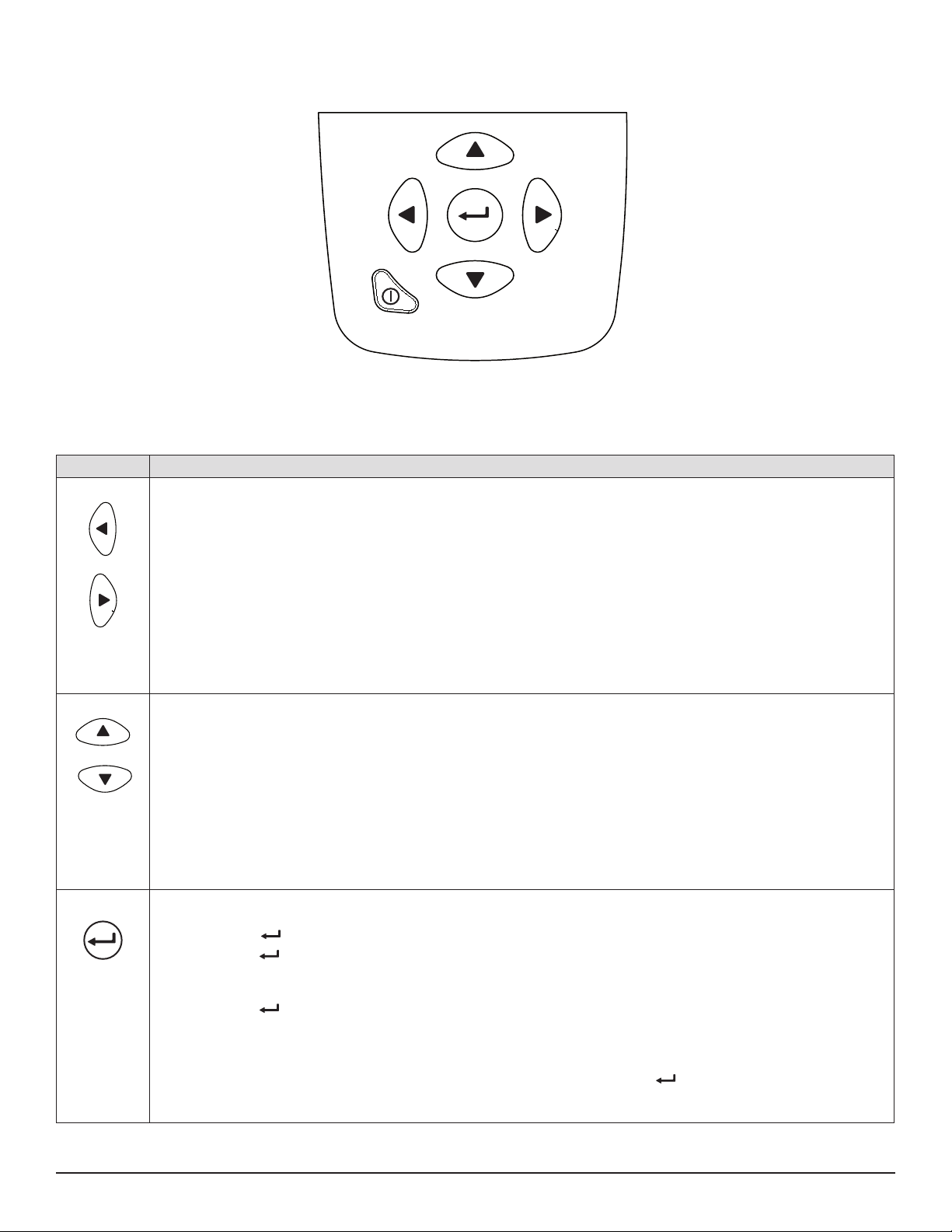
2.3.2 Front Panel Buttons
The Model L452 interface also includes a set of buttons:
Figure 3
These buttons, in conjunction with the LCD, provide the built-in ability to congure the instrument and view measurement data, without
requiring a computer connection.
Button Description
Left and Right: These buttons move from one category/column of screens to the next. Pressing ► while viewing
any measurement data screen displays the top-level recording screen. Pressing ◄ while any recording screen is
displayed returns you to the top-level measurement data screen. This functionality is “circular” – pressing ◄ while a
measurement data screen is displayed navigates to the top-level instrument information screen; pressing ► while an
instrument information screen is displayed goes to the top-level measurement data screen.
- In selection mode, ◄ and ► move within multi-part input elds such as Recording Duration.
- In edit mode, ◄ and ► are individually inactive in option selection elds, and active in text and numeric entry
elds.
- Pressing both buttons simultaneously terminates the editing session without saving any changes and returns
to navigation mode.
Up and Down: These buttons navigate through the individual screens in a category. Pressing ▼ while in the top-
level measurement data screen (Channels 1 & 2 Measurement Data) displays the Channel 1 Measurement and Min/
Max Data screen; pressing it again displays the Channel 2 Measurement and Min/Max Data screen, and so on. This
functionality is “circular” - pressing ▼ while a bottom-level screen is displayed returns you to the top-level screen in
that column.
- In selection mode ▲ and ▼ navigate to user-editable elds on the screen; as you do, the currently selected
eld blinks in reversed text.
- In edit mode ▲ and ▼ either (1) cycle through the available options for the eld, or (2) enter text characters in
text-editable elds such as Bluetooth Name.
Enter: This button, when pressed at a user-congurable screen, enables you to select and change displayed set-
tings. (Pressing at an information-only screen has no eect.)
- Pressing once initiates selection mode. This causes the rst user-congurable eld in the screen to be
highlighted in blinking reversed (light on dark) text. You can then use ▲ and ▼ to navigate to other user-edit-
able elds on the screen; as you do, the currently selected eld blinks.
- Pressing a second time while positioned on a blinking eld initiates edit mode. This enables you to change
the settings for that eld. The selected eld stops blinking but remains highlighted in reversed text. You can
then use ▲ and ▼ to cycle through the available options for the eld, or enter text characters in text-editable
elds.
- When the desired option is displayed (or text entry is complete), pressing a third time ends the editing session, saves the conguration changes, and returns to navigation mode.
10
Data Logger Model L452
Page 13
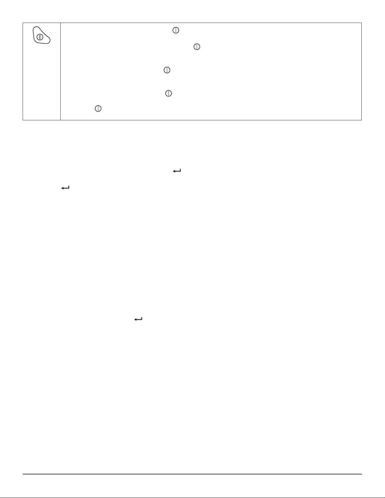
Power: In Local mode, pressing the Power button for longer than two seconds either turns ON the instrument
when it is OFF or turns OFF the instrument when it is ON.
- When the instrument is OFF, a short press of displays a graphic that indicates how much power remains in
the instrument’s batteries.
- When the instrument is ON, a short press of this button acts as a “home” button. No matter where you are in the
screen interface, a short press of cancels the operation and returns you to the Channels 1 & 2 Measurement
Data screen. In addition, if the instrument is ON but in screen saver mode (the display is blank), a short press of
this button displays the Channels 1 & 2 Measurement Data screen.
- In Remote mode, a short press of has no eect. Holding down this button for approximately two seconds
displays a message informing you that you are in Remote mode. To turn OFF the instrument, continue to hold
down while the Remote Mode message is displayed; after approximately two seconds the L452 will turn
OFF.
2.3.3 Entering Text
There are two screens (Units and Bluetooth Name) in which you are prompted to enter text. To do this, you must enter edit mode and then
use the navigation buttons to move through the elds in these screens and enter text. The steps for doing this are as follows:
1. With an editable screen displayed, press the Enter button once. This initiates selection mode. The rst character of the
editable eld will blink.
2. Press again to enter edit mode. The rst character of the editable eld will appear in solid reversed text.
3. To change the selected character, use the Up ▲ or Down ▼ button. If the selected character is a number, pressing ▲
increases that number by one and pressing ▼ decreases it by one. If the character is a letter, pressing ▲ or ▼ displays the
next or previous letter respectively. If the character is a non-alphanumerical character (punctuation mark, blank space, and so
on) pressing ▲ or ▼ cycles through the list of all available characters.
For example, suppose that the selected language is English and the rst character of the eld is blank. Holding down ▲ cycles
through (1) punctuation marks, (2) the numbers 0 through 9, (3) uppercase letters, (4) lowercase letters, and (5) mathematical
symbols. Continuing to hold down ▲ displays a blank space, after which the cycle repeats. Holding down ▼ performs the
same cycle in reverse.
4. When the desired character appears, press ► to move to the next character in the eld. You can now use ▲ or ▼ to change
the highlighted character.
5. If you need to modify a previous entry, press ◄ to return to the character to be changed.
6. When entering numerical data in elds that allow for decimal values (such as the screens for setting low and high scaling),
you can move the decimal point by pressing the ◄ and ► buttons. For example, pressing ► when the right-most character
is highlighted moves the decimal point to the left. Similarly, pressing ◄ when the left-most character is highlighted moves the
decimal point to the right.
When you have nished entering text, press to save your changes, exit edit mode, and return to navigation mode.
Data Logger Model L452
11
Page 14

3. CONFIGURATION
Before you can use the Model L452 for the rst time, you must set the appropriate conguration variables on the instrument. Some of
these settings apply to the entire instrument (such as the instrument date and time), while others aect a specic input channel.
Note that conguration can also be performed via the DataView Data Logger Control Panel (see § 6). Conguration changes made
through the Control Panel will overwrite previous changes made through the instrument’s front panel interface, and vice versa.
Note also that conguration through the instrument’s interface is disabled when the Model L452 is in Remote mode.
In addition, you can review instrument settings. These include parameters that have been congured through the instrument interface, as
well as settings congured through the Control Panel. You can also review display-only settings, such as the instrument’s serial number.
3.1 Instrument Conguration
The following instrument conguration parameters can be set through the front panel interface:
■ Language
■ Date and time
■ Enabling/disabling Bluetooth
■ Bluetooth name
■ Enabling/disabling Bluetooth visibility
All these options are set through the instrument conguration screens. The top level screen in this set is the Language and Date/Time
Format screen. This is the starting point for all instrument conguration operations. To display this screen, proceed as follows:
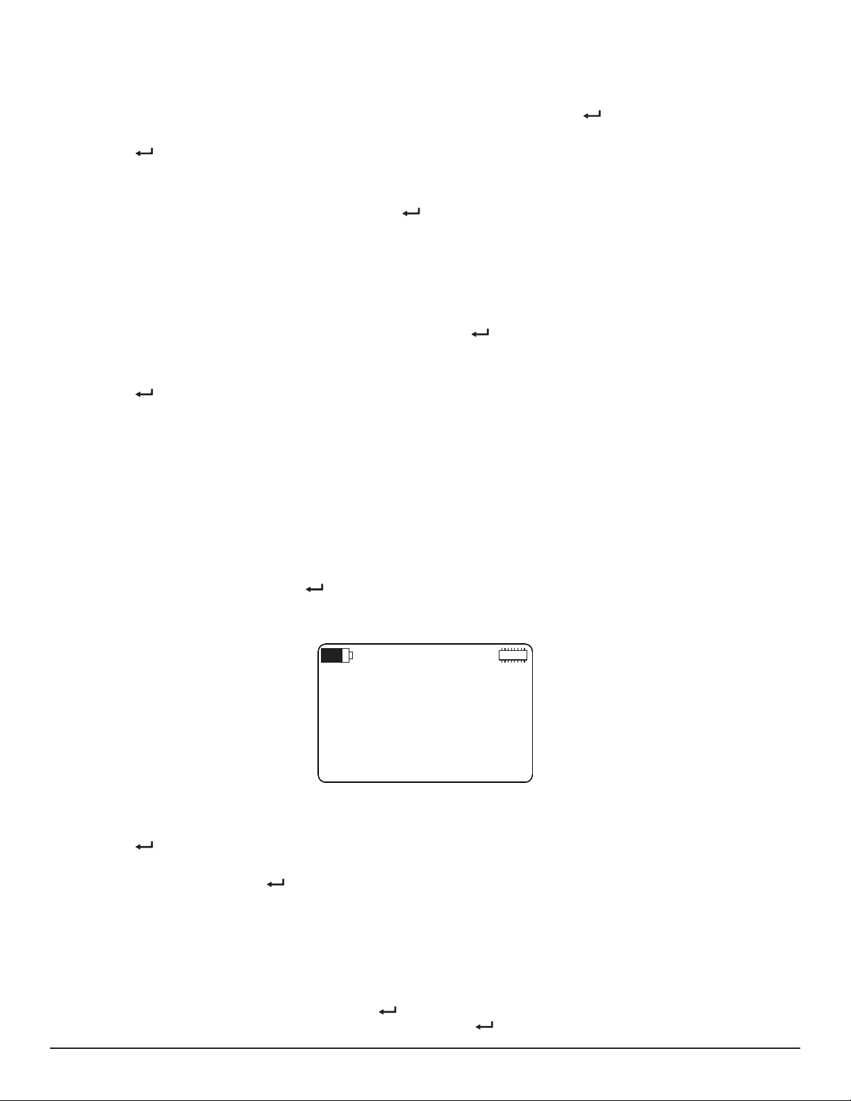
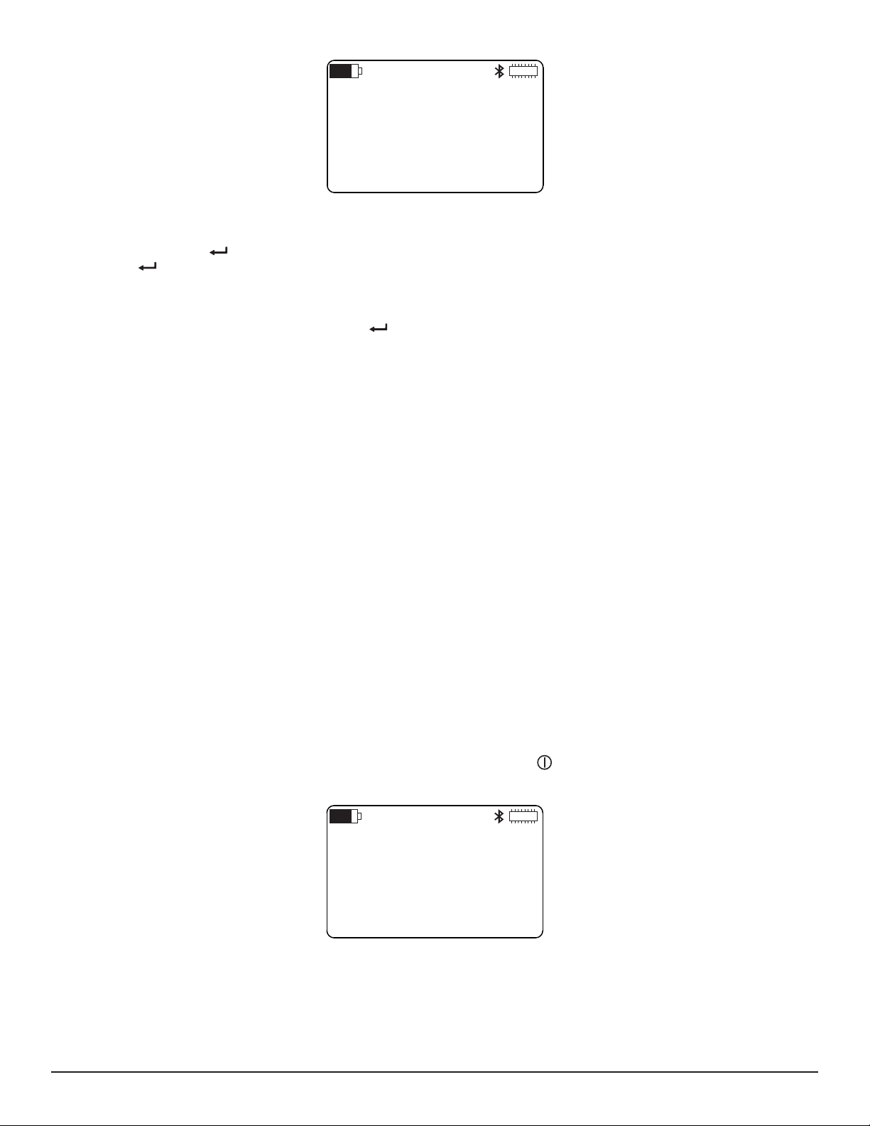
1. If the Model L452 is turned OFF, turn it ON by pressing the Power button and holding it down until the message POWER
ON appears on the LCD. (This takes approximately two seconds.) The Channel 1 & 2 Measurement Data screen then
appears.
OL
1
2
Figure 4. Channel 1 & 2 Measurement Data Screen
This is the “Home” screen for the user interface, and serves as the starting point for navigating to other screens. If the
instrument is already ON and a dierent screen is displayed, a short press of Power
Measurement Data screen.
2. With the Channel 1 & 2 Measurement Data screen displayed, press the Right ► button four times to display the Language and
Data/Time Format screen.
24.5
91.8
mV
mV
returns to the Channel 1 & 2
Figure 5. Language and Date/Time Format screen
You are now at the top-level instrument conguration screen, and can press the ▲ and ▼ buttons to display other instrument conguration
screens. Some of this information can be changed, while other information is read-only.
12
Data Logger Model L452
Page 15
3.1.1 Choosing the Language for the Interface
Date:
11/12/15
Time:
10:29:15
Text on user interface screens can be displayed in English, French, Spanish, Italian, and German. To select a language, do the following:
1. With the Language and Date/Time Format screen (Figure 5) displayed, press the Enter button. This initiates selection
mode; the setting under the Language eld will change to blinking reversed text.
2. Press again to enter edit mode. The Language setting now appears in solid reversed (light on dark) text.
3. Use the ▲ or ▼ button to cycle through the available languages. Choices are English, Español, Italiano, Deutsch, and
Français.
4. When the desired language choice is displayed, press . The text on all screens now appears in the selected language.
3.1.2 Setting the Instrument Date and Time
The Model L452 interface enables you to set or change the instrument’s date and time. You can also choose the format in which date and
time information is displayed. To do this:
1. With the Language and Date/Time Format screen displayed, press . This initiates selection mode; the setting under the
Language eld will change to blinking reversed text.
2. Press ▼. The setting under Date/Time appears in blinking reversed text.
3. Press to initiate edit mode.
4. Press ▲ or ▼ to cycle through the available options for date and time format. Choices are:
MM/DD/YY AM/PM. The date will appear in month/day/year format, and the time will appear in AM/PM format. For example,
with this setting December 25, 2015 at 3:00 PM will appear as: 12/25/15 3:00 PM.
MM/DD/YY 24h. The date will appear in month/day/year format, and the time will appear in 24-hour (military) format. For
example, with this setting December 25, 2015 at 3:00 PM will appear as: 12/25/15 15:00:00.
DD/MM/YY AM/PM. The date will appear in day/month/year format, and the time will appear in AM/PM format. For example,
with this setting December 25, 2015 at 3:00 PM will appear as: 25/12/15 3:00 PM.
DD/MM/YY 24h. The date will appear in day/month/year format, and the time will appear in 24-hour (military) format. With this
setting December 25, 2015 at 3:00 PM will appear as: 25/12/15 15:00:00.
5. After you make your selection, press to save it. All elds on the Language and Date/Time Format screen should now
appear in regular text.
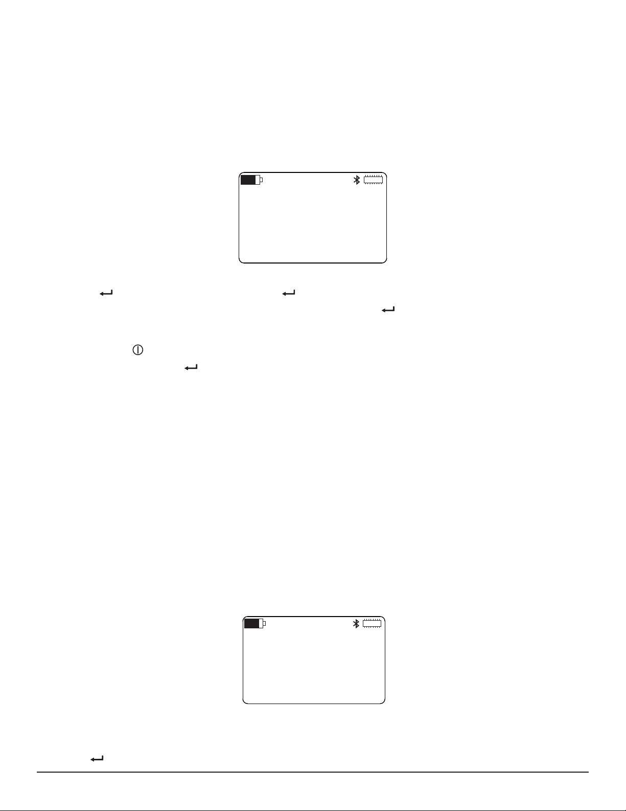
6. Press ▼ three times. The Date and Time screen now appears.
Note that in Figure 6, the date and time appear in MM/DD/YY 24h format, as selected in step 4 of this procedure.
7. Press once to initiate selection mode. The rst number in the Date eld (which in MM/DD/YY format is the month, and in
DD/MM/YY format is the day) will blink.
8. To change this number, press to initiate edit mode. Then use the ▲ and ▼ buttons to increase/decrease this number until
the correct value is displayed.
9. To change the other two settings in the Date eld, press ► to navigate to the number you want to set. Then press ▲ or ▼ to
change the setting. You can also use ◄ to navigate back to a previous number.
10. To change the Time eld, press ► while the last number in the Date eld is selected. This highlights the rst number in the
Time eld.
Alternatively, if you are not in edit mode (for example, you have opened the Date and Time screen and only want to change
the time while leaving the date unchanged), press to initiate selection mode. Then while the rst number in the Date eld is
blinking, press ▼. The rst number in the Time eld will blink; press to initiate edit mode.
Data Logger Model L452
Figure 6. Date and Time Screen
13
Page 16
11. Change the numbers in the Time eld, using the buttons as explained in the steps above.
Bluetooth:
Enabled
Visibility:
Visible
12. When you have nished setting the Date and Time values, press to save your changes and leave edit mode.
3.1.3 Enabling and Conguring Bluetooth
The Model L452 can be connected to a computer running DataView. Once connected, you can use DataView’s Data Logger Control Panel
to view real-time data measured by the instrument, congure settings, start a recording session, and download recorded data for distribution and analysis. There are two ways to establish this connection. One is by using a USB cable to directly connect the Model L452 to the
computer (see § 6.3.1). The other is through Bluetooth, a protocol designed to allow devices to communicate wirelessly.
Connecting to a computer with Bluetooth involves three general tasks:
1. Enable and congure Bluetooth on the computer. The steps for doing this depend on the type of computer you are using, and
whether it has built-in Bluetooth capability or requires a USB-to-Bluetooth adapter. Consult the documentation that comes with
your computer for information about how to enable and congure Bluetooth.
2. Enable and congure Bluetooth on the Model L452.
3. Pair and connect the instrument to the computer using Bluetooth. This is done on the computer, and is described in § 6.3.2.
The instrument’s Bluetooth range under ideal conditions can be up to 100 meters (approximately 328 feet) line-of-sight, although outside
interference, dierent adapter types, and other factors can reduce this range. The data transmission rate is 115 kbits/s. Note that disabling Bluetooth when the L452 does not need to communicate with a computer (for example, during a long recording session) decreases
power consumption and lengthens the life of the instrument’s batteries.
To enable and congure Bluetooth on the Model L452, do the following:
1. With the Language and Date/Time Format screen displayed, press ▼ four times. This displays the Bluetooth Enabled/Visibility
screen:
2. To change the Bluetooth setting, press once to initiate selection mode. Then press a second time to initiate edit mode.
3. Use the ▲ or ▼ button to toggle through the two options Enabled and Disabled. When the desired option is displayed, press
to save the selection and leave edit mode. When the Enabled option is selected, the Bluetooth icon appears in the icon
bar.
4. To change the Visibility setting, press to initiate selection mode. Then press ▼ to select the Visibility eld. Press to
initiate edit mode, then use ▲ or ▼ to toggle through the two options Visible and Invisible.
Typically, you will initially set this option to Visible so the Model L452 will appear in your computer’s list of Bluetooth devices
available for pairing. After you pair the instrument on the computer, you can then change this eld to Invisible to avoid it
showing up in the list of available devices for other computers within range of the Bluetooth transmitter. This prevents other
computers from gaining unauthorized access to the instrument via Bluetooth.
When the correct option is selected, press to save the setting and leave edit mode.
5. You can now change the Bluetooth name. This is the name by which the instrument will appear in the computer’s list of
available Bluetooth devices. By default, this name is “L452-” followed by the instrument’s serial number. To change this, press
▼ at the Bluetooth Enabled/Visibility screen. This displays the Bluetooth Name screen.
Figure 7. Bluetooth Enabled/Visibility screen
14
Data Logger Model L452
Page 17
Bluetooth
Name:
L452-452105MLP
Figure 8. Bluetooth Name screen
6. The Bluetooth name consists of two parts. The rst part is “L452-“ and cannot be changed. The second part is editable. To
change this, press once to initiate selection mode; the rst character in the editable part of the Bluetooth name blinks.
Press a second time to initiate edit mode, and change the character using ▲ or ▼.
7. You can now change other characters in the Bluetooth name. Press ► to highlight the next character and use the ▲ and ▼
buttons to make your change. You can also press ◄ to navigate back to a previous character.
8. When you are nished editing the name, press to save your changes.
The instrument can now be paired and connected to the computer via Bluetooth (see § 6.3.2).
3.2 Channel Conguration
In addition to general instrument settings, you can also set parameters for channel 1 and channel 2. Each channel has its own set of
conguration screens; the screens for one channel are essentially identical to the screens for the other. These screens allow you to:
■ Enable and disable the channel. When disabled, measurements are neither recorded nor displayed for the channel.
■ Select the type of input. This can be analog (voltage or current), pulse, or event. Note that both channels must have the
same input type.
■ Dene measurement units. These units are used when displaying measurement data.
■ Dene scaling. This establishes the relationship between input and measurement units.
■ Enable and dene alarm triggers. This determines whether or not (and under what circumstances) the L452 reports an alarm
condition.
■ Dene how pulse input equates to measurement units.
■ Dene the circumstances under which the Model L452 reports an event.
The following sections explain how to perform these tasks. The starting point for these procedures is either the Channel 1 Enable/Disable
screen or the Channel 2 Enable/Disable screen, depending on which channel you want to congure. These are the top-level screens for
conguring channel 1 and channel 2 respectively. To display these screens:
1. Display the Channel 1 & 2 Measurement Data screen. This screen appears when you rst turn ON the L452. If the instrument
is already ON but is displaying a dierent screen, a short press of the Power button returns you to this screen.
2. Press ► twice to display the Channel 1 Enable/Disable screen, or three times to display the Channel 2 Enable/Disable screen.
CHANNEL 1:
ENABLED
INPUT:
PULSE
Figure 9. Channel 1 Enable/Disable screen
In the following sections, we describe conguring channel 1. However, these instructions apply equally to conguring channel 2.
Data Logger Model L452
15
Page 18

3.2.1 Enabling and Disabling Channels
The rst eld shown in Figure 9 enables and disables the channel. By default, both channels are enabled. To change this setting, do the
following:
1. At the Channel Enable/Disable screen, press once to initiate selection mode. The setting under Channel will blink.
2. Press a second time to initiate edit mode.
3. Use ▲ and ▼ to toggle between the options Enabled and Disabled. When the correct option is displayed, press to save
the setting.
When a channel is disabled, it does not display or record measurement data.
Note that both channels cannot be disabled at the same time. If channel 1 is disabled, and you disable channel 2, channel 1 will automatically become enabled. This prevents running a recording session with both channels erroneously disabled.
3.2.2 Selecting the Input Type
The second eld shown in Figure 9 denes the input type for the two channels. This input type applies to both channels, and needs to
match the output type of the sensor, signal conditioner, or probe connected to this channel. The following input types are supported:
■ Voltage (±100mV, ±1V, and ±10V)
■ Current (4 to 20mA)
■ Pulse
■ Event
Voltage and current input types are collectively known as analog input.
3.2.2.1 Analog
Voltage and current input can be scaled to user-selected measurement units. For example, if a mass ow meter outputs 4mA at 0 sccm
and 20mA at 100 sccm, you can specify the following:
■ Input type: 4 to 20mA
■ Units: sccm (see § 3.2.3)
■ Low scaling: display a measurement of 0 sccm when the input is 4mA (§ 3.2.4)
■ High scaling: display a measurement of 100 sccm when the input is 20mA (§ 3.2.4)
Sampling period, storage period, and other user-congurable parameters associated with recording and displaying data, can be set for
both voltage and current input as explained in § 5.
3.2.2.2 Pulse Count
You can dene the “equivalence” setting for a pulse – in other words, the actual displayed measurement value that each pulse represents
(see § 3.2.6).
3.2.2.3 Event
Event input can range from -10V to +10V, sampled 16 times per second. An event is dened as a transition between a sample that mea-
sures higher than 1V and an adjacent sample (either preceding or following) that measures 1V or lower.
To select the channel’s input type:
1. At the Channel Enable/Disable screen, press once to initiate selection mode. The setting under Channel will blink.
2. Press ▼ to highlight the input setting.
3. Press to initiate edit mode.
16
Data Logger Model L452
Page 19

4. Use ▲ and ▼ to cycle through the available input type options: ±100 mV, ±1 V, ±10 V, 4-20 mA, Event, and Pulse.
5. When the correct input type is selected, press to save the setting.
Note that both channels must have the same input type; you cannot select one input type for one channel and a dierent type for the
second. For instance, if you select Pulse for channel 1 and then select Event for channel 2, the input type setting for channel 1 will automatically be changed to Event to match channel 2.
3.2.3 Dening Units
If the input type is set to analog (voltage or current) or pulse, you can specify the units to which the input measurements will be converted
for display. The following steps explain how to do this:
1. At the Channel Enable/Disable screen, press ▼. This displays the Units screen. (This screen does not appear if the input type
is set to Event.)
CHANNEL 1:
UNITS
Figure 10. Units screen
2. Press once to enter selection mode, then press a second time to begin edit mode.
3. Enter the units, using the buttons as explained in § 2.3.3. These units can be anything you choose. The maximum length of the
unit name is four characters.
4. When you have nished entering the units, press to save the setting.
Note that if you do not specify a unit, the following defaults will be used, depending on input type:
■ mV for ±100mV input
■ V for ±1V and ±10V input
■ mA for 4-20mA input
■ Wh for pulse input
3.2.4 Selecting Low and High Scaling Factors
As noted previously, the analog input received by each channel can be “scaled” to its dened units. To do this, you must dene both the
low scale (the measurement value when the input is at a pre-set low value) and high scale (the measurement value when the input is at
maximum). This enables the L452 to correctly interpret the input it receives from the connected probe or sensor and then display mea-
surement data in the selected units.
Scaling determines the accuracy of the instrument’s displayed measurements. Dierent sensors and probes have dierent scaling requirements; consult the specications that come with your sensor/probe to set the scaling correctly on the L452.
For example, suppose a temperature probe measures a range from -40 to 80°C. At -40°C, the probe’s current output is 4mA, and at
80°C the output is 20mA. To ensure the L452 displays data from this probe correctly, you must scale 4mA input received from the probe
to display a reading of -40°C, and scale 20mA input to 80°C. This scaling is then used to convert the input to the displayed temperature
readings. To do this:
1. At the Channel Enable/Disable screen, press ▼ twice. This displays the Scale Low screen. (This screen does not appear if the
input type is set to either Pulse or Event.)
Data Logger Model L452
17
Page 20

CHANNEL 1
SCALE LOW:
4.00 mA
=-40.00 degC
Figure 11. Scale Low screen
2. This screen displays the low input value, as determined by the input type. For example, if the input type is set to 4-20 mA,
the displayed value is 4.00 mA, as shown in Figure 11. Below this eld is the value to which the input setting will scale. This
is expressed in the measurement units dened in the Units screen. To change this setting, press once to enter selection
mode, then press a second time to begin edit mode.
3. Enter the low scale measurement value, using the buttons as explained in § 2.3.3. Allowable values are oating point numbers
in the range of +/- 0.999 to 999.9; these values must not fall outside the range dened by the selected input. The value can be
a negative number.
In Figure 11 we have set the low scale measurement value to “-40.00 degC.” This means that when channel 1 receives 4mA
input from the probe, the LCD will display this data as “-40 degC.”
4. When you have nished entering the low scale measurement value, press to save the setting and exit edit mode.
5. You must now set the high scale value. In our example, we will scale 20mA input to a measurement value of 80°C. To do this,
with the Scale Low screen displayed press ▼ once. This displays the Scale High screen.
CHANNEL 1
SCALE HIGH:
20.00 mA
= 80.00 degC
Figure 12. Scale High screen
6. This screen functions similarly to the Scale Low screen except (as the name suggests) it denes what the measurement value
should be when the input reaches its maximum value. Note that the measurement value entered in the Scale Low screen
can be higher than the value entered in the Scale High screen. This is useful in cases where a rising input voltage or current
corresponds with a decreasing measurement value.
In Figure 12 we have set the high scale value to “80.00 degC.” This means that when channel 1 receives 20mA input from the
probe, the LCD will display this data as “80 degC.”
7. When you have nished entering the high scaling value, press to save the setting.
Note that by default, scaling is one-to-one. In other words, one input unit equals one measurement unit. Also note that neither scaling
screen is displayed if the input type is set to Pulse or Event.
18
Data Logger Model L452
Page 21

3.2.5 Enabling and Dening Alarm Triggers
When enabled, an alarm is triggered when the measurement on either channel meets a user-dened criterion such as exceeding or falling
below a certain value. When this happens, the Alarm icon appears in the icon bar at the top of the LCD.
To enable and dene an alarm, do the following:
1. At the Channel Enable/Disable screen, press ▼ four times. This displays the Alarm Trigger screen. (This screen does not
appear if the input type is set to Pulse or Event.)
ALARM TRIGGER:
ABOVE UPPER
Figure 13. Alarm Trigger screen
2. Press to enable selection mode, and then press again to begin edit mode. You can now set the Alarm Trigger eld.
Options are:
Disabled. When disabled, alarm detection is not active for this channel.
Outside Limits: The alarm is triggered when the measurement falls outside the range dened by the upper and lower limits
settings (see below). The Alarm icon is displayed if the measurement falls either below the lower limit or rises above the
upper limit.
Within Limits: The alarm is triggered when the measurement falls within the range dened by the upper and lower limits
settings. The Alarm icon is displayed if the measurement is both above the lower limit and below the upper limit.
Below Lower: The alarm is triggered when the measurement falls below the lower limit setting.
Above Upper: The alarm is triggered when the measurement exceeds the upper limit setting.
3. Use ▲ or ▼ to cycle through the options. When the correct option is displayed, press to save the selection.
4. You can now set the upper and/or lower limits that will trigger the alarm. Do this by pressing ▼ at the Alarm Trigger screen.
This displays the Upper and Lower Limits screen.
UPPER LIMIT:
50.00 degC
LOWER LIMIT:
-10.00 degC
Figure 14. Upper and Lower Limits screen
If the trigger you selected in step 3 is Above Upper, the Lower Limit eld is inactive because it is irrelevant for dening the
alarm condition. Similarly, if the trigger is Below Lower the Upper Limit eld is inactive. The steps below assume that both the
Upper Limit and Lower Limit elds are active.
5. To change the upper limit setting, press to initiate selection mode, then press a second time to begin edit mode. Set the
upper limit, using the instrument’s buttons as described in § 2.3.3. When nished, press to save the change and leave edit
mode.
6. To change the lower limit, press to initiate selection mode. Then press ▼ to select the lower limit value.
7. Press to begin edit mode, and enter the lower limit value. Note that if both limits are used (in other words, the trigger is set
to either Outside Limits or Within Limits), the lower limit cannot be higher than the upper limit.
8. When you have nished setting the lower limit, press to save your change.
Data Logger Model L452
19
Page 22

3.2.6 Dening Equivalence (Pulse Input Only)
CHANNEL 1
EQUIVALENCE:
1.00 Pulse
= 0.1 Wh
Similar to analog input, pulse input can be “mapped” to measurement units. To do this, you must dene the relationship between one pulse
and the measurement units you have selected:
1. At the Channel Enable/Disable screen, press ▼ twice. This displays the Equivalence screen. (This screen only appears when
the input type is set to Pulse.)
Figure 15.Equivalencescreen
2. Press to initiate selection mode, then press again to begin edit mode. Then type in the measurement value that each
pulse represents, using the buttons as described in § 2.3.3. Allowable values for the pulse equivalence are positive oating
point numbers in the range of .0001 to 9999. For example, in the preceding illustration we have dened one pulse as being
equivalent to 0.1Wh.
3. When you have nished entering the equivalent measurement value of one pulse, press to save your changes.
Note that by default, one pulse equals one Wh.
3.2.7 Selecting Event Trigger (Event Input Only)
Event input consists of data that indicates whether or not an event (a transition between low and high states) has taken place. You can
enable event input by selecting Event in the Channel Enable/Disable screen (see Figure 9). An event can be either rising or falling:
■ A rising event is triggered when input transitions from a low state (input equals 1V or less) to a high state (input exceeds 1V).
■ A falling event is triggered when input transitions from high to low.
To dene which type of event you want the L452 to report, do the following:
1. At the Channel Enable/Disable screen, press ▼. This displays the Event Trigger screen. (This screen only appears when the
input type is set to Event.)
TRIGGER:
RISING
Figure 16.EventTriggerscreen
2. Press to initiate selection mode, then press again to begin edit mode. Press ▲ or ▼ to toggle between the available
options Rising and Falling.
3. When you have nished selecting the event trigger type, press to save your changes.
20
Data Logger Model L452
Page 23
3.3 Restoring Conguration to the Original Settings
You can override all conguration changes and restore parameters back to their original factory default settings. This resets all conguration modications other than the instrument’s date and time. This also applies to any changes made through the DataView Data Logger
Control Panel. This process also resets the minimum and maximum values on the instrument back to zero.
Note that this does not aect any recorded data stored in the instrument. Erasing memory requires a separate procedure, as explained
in § 8.1.1.
To reset the conguration parameters to their original settings, follow the steps below:
1. With the Language and Date/Time Format screen (Figure 5) displayed, press ▼ twice. This displays the Conguration Reset
screen.
CONFIGURATION:
NO ACTION
Figure 17.CongurationResetscreen
2. Press to initiate selection mode and then press a second time to begin edit mode.
3. Press ▲ or ▼ to display the option Reset. With this option displayed, press .
4. A message appears asking you to conrm the reset. To exit this message without resetting the conguration, press the ◄ and
► buttons simultaneously. This returns you to the Conguration Reset screen, without taking any further action. Alternately, a
short press of returns to the Channel 1 & 2 Measurement Data screen (see Figure 4).
To conrm the reset, press . All conguration parameters other than time and date are restored to their original settings.
After a short pause, during which the screen will briey appear blank and then display the Model/Serial Number/Firmware
screen (see Figure 18) for several seconds, you are returned to the Channel 1 & 2 Measurement Data screen.
3.4 Viewing Instrument Information
You can at any time view current instrument information, including:
■ Model and serial number
■ Firmware revision currently running on the instrument
■ Instrument name and location
■ Number of recording sessions currently stored in memory
■ Amount of available memory
■ Default name for the next recording session
The user interface includes a set of instrument information screens for viewing these settings. To view the top-level instrument information
screen, display the Channel 1 & 2 Measurement Data screen (Figure 4). Then either press ◄ once or ► ve times. The Model/Serial
Number/Firmware screen appears:
L452
SN: 452101MLP
FIRMWARE: 1.00
Figure 18. Model/Serial Number/Firmware screen
This screen is the starting point for viewing instrument information. Note that instrument information screens remain accessible in Local
mode when a recording is active. They are, however, inaccessible in Remote mode. Note also that when viewing instrument information
screens, the button is disabled, preventing you from entering either selection or edit mode.
Data Logger Model L452
21
Page 24

3.4.1 Model, Serial Number, and Firmware Revision
RECORDING
SESSIONS: 4
FREE
MEMORY: 29.66 MB
As shown in Figure 18, this screen displays three elds of data:
■ Model of the instrument. This is always L452 and cannot be changed.
■ Serial number of instrument: This is a factory setting and cannot be changed.
■ Firmware revision currently running on the instrument. You can download the latest rmware, as instructed in § 8.1.2. When
you do, this number is updated. You cannot change the rmware number directly via this screen, however.
3.4.2 Name and Location Screen
This screen displays the instrument’s name and location. To view this screen, go to the Model/Serial Number/Firmware screen and press
▼.
NAME:
L452-452105MLP
LOCATION: AEMC
Figure 19. Name and Location screen
This screen displays two elds:
■ Name is the name by which the instrument will be identied. This can be up to 32 characters long. By default, this is “L452”
followed by the instrument’s serial number. You can change this name via the DataView Data Logger Control Panel (see § 6).
However, you cannot change this name through the Model L452 interface.
■ Location identies where the instrument is located. This can be up to 32 characters long. This is entered through the Data
Logger Control Panel and cannot be modied through the Model L452 interface.
3.4.3 Recording Session Screen
This screen displays the number of recording sessions (if any) currently stored in memory. It also shows the amount of free memory left
for storing additional recording sessions. To view this screen, display the Model/Serial Number/Firmware screen and press ▼ twice.
Figure 20.RecordingSessionsscreen
Note that this screen appears even if no sessions are currently stored in the instrument’s memory. In this case, Free Memory will be 31.88
MB.
22
Data Logger Model L452
Page 25

3.4.4 Recording Name Screen
RECORDING
NAME:
L452-452105MLP 1
Each recording session has a name, which the instrument assigns by default. When conguring a recording through the Control Panel,
you can change the default recording name and assign the recording any name you choose. When conguring a recording session
through the instrument’s interface, you cannot change the session name; the name assigned by the instrument is the only session name
available.
To view the name for the next recording session, display the Model/Serial Number/Firmware screen and press ▼ three times:
Figure 21.RecordingNamescreen
By default, the recording name consists of the instrument name and a numerical sux that represents the session number (the number
of sessions currently stored in memory plus one). For example, in Figure 21 this number is 1, indicating that no sessions are currently
stored in the instrument’s memory.
As noted above, the recording name can be changed via the DataView Data Logger Control Panel. When the Control Panel starts or
schedules a recording session, the name given to that session becomes the default name until (1) the Control Panel starts or schedules
a recording under a dierent name, or (2) the user resets the conguration on the instrument (see § 3.3).
Data Logger Model L452
23
Page 26
4. CONNECTING TO INPUTS & VIEWING MEASUREMENTS
4.1 Connecting Probes, Signal Conditioners, and Sensors
After you have nished conguring the instrument, you are now ready to connect sensors or probes to the instrument and start taking
measurements. The Model L452 works with a wide variety of measurement probes, signal conditioners, sensors, and devices that output
data as voltage (±100mV, ±1V, or ±10V), current (4 to 20mA), pulses, or events.
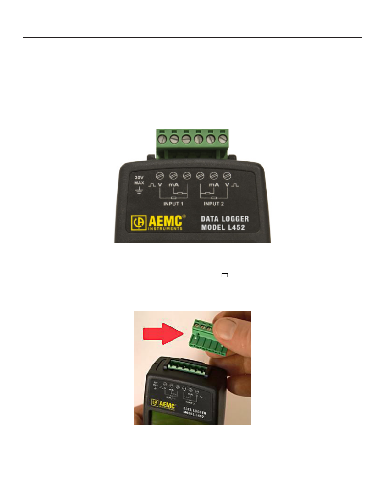
There is a removable six-pin terminal strip that can accept input from two separate sources. Each input has a set of three screw terminals.
Each set has an unlabeled common screw used by all types of measurement input. Of the remaining two screws, one is used for 4-20mA
input, while the other is used for voltage, pulse, and event input.
Figure 22. Measurement inputs
For example, to connect input 1 to a probe that produces mA output, connect one lead to the screw labeled mA (second from the left in
Figure 22) and the other lead to the unlabeled common screw (third from the left). To connect input 1 to a probe or device that produces
voltage, pulse, or event measurements, connect one lead to the screw labeled V (far left) and one to the same common screw used
for the mA probe. Connecting a probe to input 2 is a similar process.
To connect a sensor or probe, do the following:
1. Local the six-pin terminal strip.
Figure 23. Terminal strip (upper right)
2. Insert the terminal strip into the connector socket at the top of the instrument.
3. Insert the sensor, signal conditioner, or probe leads into the terminal strip. Consult Figure 22 for an illustration of how to
properly connect the leads for each type of probe/sensor. Fasten each lead by tightening the terminal screw with a screwdriver.
24
Data Logger Model L452
Page 27

Figure 24. Inserting a lead into the terminal strip
1
2
24.5
91.8
psi
m3/s
4. Connect the second probe, signal conditioner, or sensor (if used).
With the probe(s) attached, you are now ready to view data measurements, as explained below.
4.2 Viewing Measurement Data
The interface includes three screens for displaying measurement data. The rst screen shows the active measurements for both channel 1 and channel 2. The next two screens are channel-specic; they show measurement and min/max data for channel 1 and channel
2 respectively. For all these screens, when the measured input of an analog channel exceeds 110% of the selected input range for that
channel, the screen displays “OL” instead of a numeric value, and the Overload icon appears in the icon bar.
As noted earlier in this User Manual, the top-level measurement data screen (Channels 1 & 2 Measurement Data) also serves as the
Home screen. This is the screen that appears when you rst turn ON the instrument. The data displayed depends on the selected input
type for these channels. To view the channels-specic screens, display the Channels 1 & 2 Measurement Data screen and then press ▼
once (for channel 1) or twice (for channel 2).
4.2.1 Analog Measurement Data
The following illustration shows the Channels 1 & 2 Measurement Data screen with an analog input type (voltage or current):
Figure 25: Channels 1 & 2 Measurement Data screen (analog input)
The rst line of data in the screen (labeled 1) displays measurement data for channel 1, and the second (labeled 2) shows measurement
data for channel 2. The format of the data displayed for each line is dependent upon the conguration of the respective channel. For
example, in Figure 25 the measurement units for channel 1 is “m3/s” (representing cubic meters per second) and the measurement units
for channel 2 is psi.
The second and third measurement data screens display measurements and (for analog input) minimum/maximum data for channel 1
and channel 2 respectively. These screens function identically for both channel 1 and channel 2. The following shows an example of the
channel 1 screen for analog input.
Data Logger Model L452
25
Page 28

1
2.54
m3/s
MAX
MIN
Figure 26. Channel 1 Measurement and Min/Max Data screen (analog input)
For analog input types, the displayed data is the averaged value of the samples over the previous storage period. (Note that this is derived
dierently from the measurement data shown in Figure 25, which samples and displays measurements once per second.)
This screen also displays the session’s minimum and maximum measurement values of the storage-period-averaged values. The session
minimum and/or maximum values are reset:
■ at the start of a recording
■ when the input type is changed
■ when the storage period and/or sample period are changed
■ when the instrument is turned on
You can also reset the minimum/maximum through the Min/Max setting in the Memory and Min/Max screen. To do this:
1. At the Language and Date/Time Format screen (Figure 5), press ▼. This displays the Memory and Min/Max screen.
2.54
0.22
m3/s
m3/s
MEMORY:
NO ACTION
MIN/MAX:
NO ACTION
Figure 27. Memory and Min/Max screen
2. Press to initiate selection mode, then press ▼ to select the Min/Max setting.
3. Press to begin edit mode, and press ▲ or ▼ to toggle between the choices No Action and Reset. When Reset is
displayed, press again to save the selection.
4. A screen appears asking you to conrm the reset action. If you do not want to reset the minimum and maximum values at this
time, press ◄ and ► simultaneously. This returns you to the Memory and Min/Max screen without taking further action. To
conrm the reset, press .
Note that minimum and maximum are based on measurement values rather than input values. This is to accommodate situations in which
there is inverse scaling (higher input value corresponds to lower measurement value).
For analog input, the measured value is corrected using calibration data, scaled using user-congurable scaling parameters, and displayed as a oating point value along with the user-congurable units (shown on the right of the screen). Analog values are measured
and updated every second.
26
Data Logger Model L452
Page 29

4.2.2 Pulse Count Measurement Data
1
2
Wh
Wh
24
91
2
ml
9.85
DATE: 12/12/15
TIME: 07:51:17
1
2
Pulse input is displayed in the Channels 1 & 2 Measurement Data screen as a running total number of pulses measured over a recording
session (or since the last min/max reset), multiplied by their equivalence factor, and displayed with the user congurable units:
Figure 28. Channels 1 & 2 Measurement Data screen (pulse input)
For pulse input, the Channel Max Data screens appear (for example) as follows:
Figure 29. Channel 2 Max Data screen (pulse input)
The screen displays the maximum amount of units that have been measured during a storage period since the last min/max reset, and
the date and time of the storage period with the maximum value.
4.2.3 Event Measurement Data
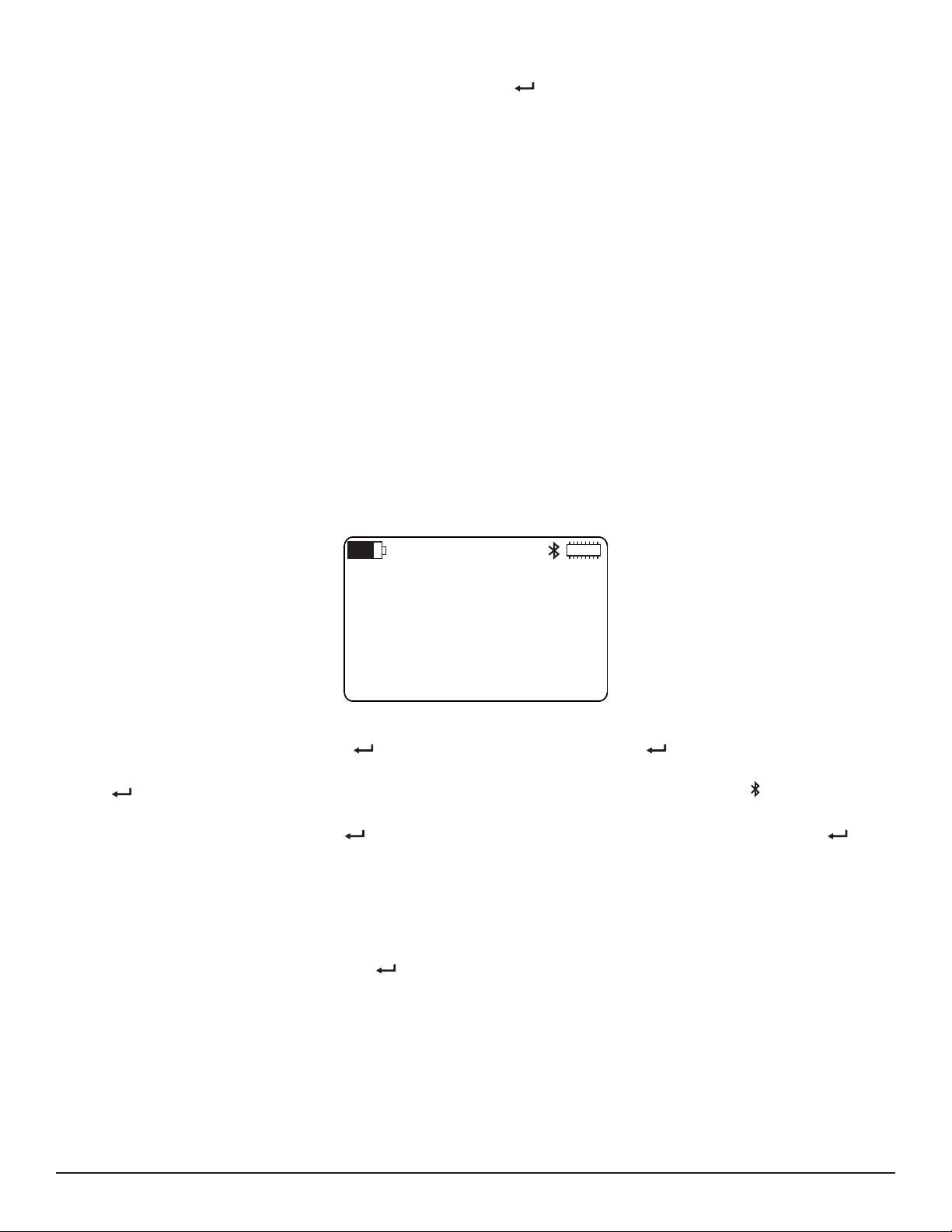
For event input, the Channels 1 & 2 Measurement Data screen appears (for example) as follows:
Figure 30.Channels1&2MeasurementDatascreen(eventinput)
An event can be dened as a transition from high (the input voltage exceeds 1V) to low (input voltage equals 1V or less). It can also
be dened as a transition from low to high. The instrument checks the input 16 times per second; the results of the last one second are
displayed at any given moment. If the input exceeds 1V (high), the icon appears for that measurement. If the input is 1V or less (low),
a at line appears instead.
For example, in Figure 30 the channel 1 input voltage exceeded 1V for all 16 measurements of the one-second displayed period; therefore
no event occurred on channel 1 during this time. On channel 2, input voltage transitioned from exceeding 1V for the 12th measurement to
equal to or less than 1V for the 13th measurement; the input signal transitioned back to exceeding 1V for the 16th measurement. When
conguring Channel 2, we selected Falling as the event trigger (see § 3.2.7). So in this instance, the transition from above 1V to below 1V
denes when the event took place; the subsequent transition from below 1V to above 1V is not considered an event.
Data Logger Model L452
27
Page 30

An example of how the Channel 1 Measurement Data screen appears for event input is shown below:
1
DATE: 11/12/15
TIME: 07:56:01
Figure 31:Channel1MeasurementDatascreen(eventinput)
This screen displays a visual representation of the last event, along with its date and time. Event data is reset when any of the following
occurs:
■ input type change
■ instrument conguration reset
■ turning OFF the instrument via the button
■ removing the batteries
Note that if no event has occurred during the last reset, the screen shows a straight line in place of the event graphic. In this case the date
and time dene when the input type was set to Event.
28
Data Logger Model L452
Page 31

5. RECORDING DATA
In addition to displaying measurement data, the Model L452 can also record measurement data and store the results in the instrument’s
onboard memory. Each recording session has a user-dened start date/time and duration, or an immediate start and duration. A session
can record data from one or both input channels. The session can then be downloaded to a computer running DataView with the Data
Logger Control Panel for further viewing, analysis, and distribution. Note that DataView is required to view the results of a recording session; you cannot display a recording session on the LCD screen.
5.1 Recording Session Overview
During each recording session, if the sample period and storage period are dierent, the average of the values sampled during each
storage period is saved in memory. The minimum and maximum sampled values for each storage period are also saved, along with the
date and time they occurred. If the sampling and storage periods are equal, no minimum/maximum values or related data are saved. As a
result, for a given storage period a recording requires ve times more memory if the sampling period and storage period dier, compared
to a recording where the sample and storage periods are the same. So to make more ecient use of memory, you should set the sample
and storage periods to the same length, unless the storage period is more than ve times longer than the sample period.
Up to 1024 recording sessions can be stored in the Model L452. The recording memory is considered full when the available space is
fully utilized, or when it contains 1024 sessions. Recording sessions can be downloaded via the DataView Data Logger Control Panel.
The Control Panel can also erase the instrument’s recording memory. In addition, you can erase recording memory via the instrument’s
LCD and button interface (see § 8.1.1).
The memory required for a recording session is largely determined by the duration of the recording as well as the sample and storage
periods. For example, a two-channel recording with a 200ms storage period will ll the instrument’s memory in approximately 19 days.
Conversely, a two-channel recording with a one minute sample period and one hour storage period would theoretically require over a
year to ll the memory. When the instrument is used without an external power source, the duration of a recording will be limited by the
amount of charge in the internal batteries.
Note that you can only record on enabled channels. To ensure that the channel(s) you want to record are enabled, check each channel’s
Enable/Disable screen (see Figure 9). If a channel you want to record is disabled (or conversely, a channel you don’t want to record is
enabled), follow the instructions in § 3.2.1.
5.2 Recording Screens
The user interface includes a set of screens for controlling and conguring a recording session. These screens enable you to:
■ Specify the sample and storage periods to be used during the recording session
■ Start a recording session immediately
■ Schedule a recording for a future time
■ Set a length of time for the recording to run
■ Schedule start/stop dates and times for the recording
■ Stop an in-progress recording
■ Cancel a scheduled recording
The starting point for working with recordings is the Recording and Duration Screen. This is the top-level screen for all recording-related
activities. To see this screen, display the Channel 1 & 2 Measurement Data screen and press ►:
RECORDING:
START
Data Logger Model L452
DURATION:
15 min
Figure 32:RecordingandDurationscreen
29
Page 32

The options available in the Recording eld depend on the current recording status:
■ If no recording is active or scheduled, the options Start and Schedule are available.
■ If a recording is in progress, the only option available is Stop.
■ If a recording is scheduled but not yet active, the only option available is Cancel. Once the scheduled recording begins, the
Cancel option is replaced by the Stop option.
Note also that when a recording is scheduled or active, this is the only recording screen for which selection mode is active. In this case,
the Recording eld is the only eld that can be selected, as explained below.
5.3 Conguring a Recording Session
Before starting or scheduling a recording session, you need to set a number of conguration options. With the Recording and Duration
screen displayed, press ▼ to display the Sample Period and Storage Period screen.
SAMPLE PERIOD:
200 ms
STORAGE PERIOD:
01 s
Figure 33. Sample Period and Storage Period screen
This screen (which is read-only when the input type is set to Event) consists of two elds. The rst is Sample Period. The Model L452 will
sample analog input at the rate dened by this eld. Allowable values are 200ms, 400ms, 600ms, or 800ms; 1 to 60 seconds; or 1 minute.
You can also dene a sample period for pulse input; this sample period is used for recording pulse counts minimums and maximums (see
below). Allowable values are the same as for analog input. For event input, the sample period is automatically set to 62.5ms and cannot
be changed.
The second eld on this screen is Storage Period. This denes the rate at which analog and pulse input sampled values are displayed
and/or recorded. For analog input, the sampled values are averaged over the storage period. When there are multiple samples in a
storage period the minimum and maximum sample values during each storage period are also recorded with the date and time of their
occurrence. For event input, the storage period is automatically set to 1s. For other input types, possible storage period values are 200ms,
400ms, 600ms, 800ms; from 1 to 59 seconds; or from 1 to 60 minute(s).
For example, to set the sample period to 1 second and storage period to 1 minute, navigate to this screen and proceed as follows:
1. Press once to enter selection mode. The numbers or units in the Sample Period eld will blink.
2. If the units part of the eld is not already selected, press ► to navigate to it. Then press to enter edit mode. The units value
should appear in solid reversed text.
3. Use the ▲ and/or ▼ buttons to cycle through options until “s” is displayed.
4. Press ◄ to go to the numeric part of the Sample Period eld. The digit on the right should be highlighted. Hold down the ▼
button until 01 is displayed.
5. Press to save the sample period setting and leave edit mode. Then press again to re-enter selection mode, and press
the ▼ button to navigate to the Storage Period eld.
6. Press to re-enter edit mode, and use the ▲, ▼, ◄, and ► buttons to change the displayed value to 01 min. Note that the
storage period must be greater than or equal to the sample period; and must also be evenly divisible by the sample period.
7. Press to save the storage period setting. For event input, both the sample period (62.5ms, or 16 times per second) and
storage period (one second) are pre-set and cannot be changed.
In addition to recording sessions, the sample and storage periods are also used to generate the minimum and maximum values displayed
in the measurement data screens (see § 4). Also note that the sample period aects power consumption and how long the instrument can
run on batteries. The shorter the sample period, the shorter the instrument can operate on battery power.
In addition to the preceding steps, before you start or schedule a recording you should ensure that there is sucient available free memory
to store the recording session. If the Memory icon indicates there is little or no free memory left (it appears as follows when full: ) you
will need to erase memory, as instructed by § 8.1.1, before you can start another recording. The Recording Sessions screen (Figure 20)
shows both the number of recording sessions currently stored, and the amount of free memory remaining to store additional sessions.
30
Data Logger Model L452
Page 33

5.4 Starting a Recording Session
RECORDING
ACTIVE
You can start a congured recording session immediately, or schedule one for a later date and time. To start a recording immediately:
1. Complete the Sample Period and Storage Period screen as instructed in § 5.3 above.
2. At the Sample Period and Storage Period screen press ▲ once. This returns you to the Recording and Duration screen
(Figure 32). Note the Duration eld on this screen. This species how long the recording session will run. By default (assuming
no session has been already scheduled), this is 15 minutes. In addition, the Duration setting cannot be shorter than the
Storage Period setting (see § 5.3). To change this duration setting, press to initiate selection mode, and press ▼ to select
the Duration eld. Then press to start edit mode, and use the buttons to enter a duration period.
For example, to change the duration from 15 minutes to 3 days, select the “1” in “15 min” and press to begin edit mode.
Use ▼ to change this to a zero, then press ► to highlight the number “5.” Press ▼ twice to change this to “3.” Finally, press
► to select the units, and use the ▲ and ▼ buttons to cycle through available choices. These include s (seconds), min, hours,
days, and weeks. Select “days” and press to save your change. (Alternately, instead of the Duration eld you can use the
Stop Date and Stop Time screen to determine how long the recording session will run, as described in § 5.5 below.)
3. To start the recording, press to select the Recording eld, and then press a second time to start edit mode. Then press
a third time. The recording session starts immediately, using the conguration settings you have specied. The recording
session will end when the time interval dened by the Duration eld comes to an end.
The name under which this recording session will be stored in the instrument’s memory is the name displayed in the Recording Name
screen (see § 3.4.4).
When a recording is active, the Recording icon appears in the icon bar at the top of the screen. This icon appears as a solid circle. If you
attempt to turn OFF the L452 by pressing while a recording is in progress, the message RECORDING ACTIVE appears on the screen.
Figure 34.RECORDINGACTIVEmessage
The button is otherwise disabled while a recording is in progress.
When the recording session is nished, it is stored in memory. The Recording Sessions screen (Figure 20) is incremented to reect the
addition of this session to the recording count on the instrument. The Free Memory eld in the Recording Sessions screen is also updated
to reect the amount of memory consumed by the recording. In addition, the Recording Name screen (Figure 21) increments the default
name for the next recording session. You can now download the session to a computer and view it through the DataView Data Logger
Control Panel (see § 6).
5.5 Scheduling a Recording Session
Instead of instructing the Model L452 to start recording immediately, you can schedule a recording for a future date and time. Note that
you can only schedule one recording at a time; to schedule a new recording (1) the active recording must run to completion, or (2) you
must cancel the earlier recording.
To schedule a recording, do the following:
1. Complete the Sample Period and Storage Period screen as instructed in § 5.3.
2. With the Sample Period and Storage Period screen displayed, press ▼ to display the Start Date/Time screen.
START DATE:
11/13/15
Data Logger Model L452
START TIME:
02:37:35AM
Figure 35. Start Date/Time
31
Page 34
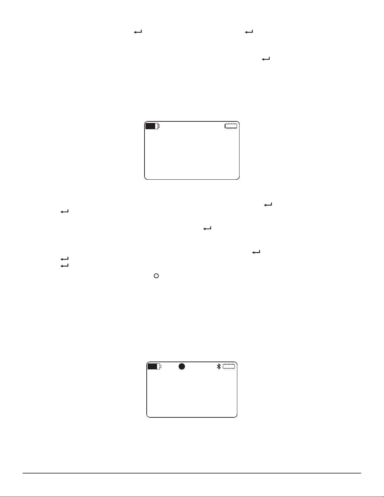
3. Note that the start date and time are formatted in accordance with the settings you entered into the Language and Date/Time
Format screen (see § 3.1.2). Press to begin selection mode, and then press a second time to start edit mode. The
rst number under Start Date will be highlighted. Use the ▲ and ▼ buttons to increase or decrease the number, and the ►
and ◄ buttons to move from one eld to the next. Note that when you press ► when the last number in the Start Date eld is
selected, the selection will move to the rst number in the Start Time eld. This enables you to edit both the date and time in a
single editing session. When you have nished entering the start date and time, press to save your changes.
4. You now have two options for dening when the recording session ends. One is by setting the Duration eld in the Recording
and Duration screen (see Figure 32). The other is through the Stop Date/Time screen.
To set the Duration eld, press ▲ twice to return to the Recording and Duration screen. Then complete the Duration eld, as
described in Step 2 of § 5.4.
To set the time and date for when the recording stops, press ▼ at the Start Date/Time screen. This displays the Stop Date/
Time screen.
STOP DATE:
11/13/15
STOP TIME:
04:39:14AM
Figure 36. Stop Date/Time screen
5. By default, the settings on this screen reect the Duration setting. For example, if the Duration eld is set to 24 hours, the stop
date and time will be set to 24 hours after the start date and time. To change this, press to start selection mode, and then
press again to initiate edit mode. Then use the buttons to select and change settings, similar to setting the start date and
time elds as described in step 3.
When you have nished entering the stop date and time, press to save your changes. The Duration eld in the Recording
and Duration screen will be updated to reect the duration dened by your start date/time and stop date/time. For instance, if
you enter a stop time 8 hours later than the start time, the Duration eld will be set to 8 hours.
6. If it is not already displayed, navigate to the Recording and Duration screen. Press to select the Recording eld, and then
press again to initiate edit mode. Then use the ▲ and ▼ buttons to cycle through the options. When Schedule appears,
press to select it.
When a recording is scheduled, the Recording icon appears in the icon bar at the top of the screen. This icon appears as an empty
circle. You can turn OFF the Model L452 with a scheduled recording pending. When the start date and time occurs, the instrument will
turn itself back ON for the duration of the recording, after which it will automatically turn OFF.
5.6 Stopping or Cancelling a Recording Session
As noted previously, you cannot start or schedule a recording session if (1) a recording is active, or (2) another scheduled recording is
pending. In either case, you will need to stop or cancel the recording before you can start or schedule another.
To stop an active recording or cancel a scheduled one, display the Recording and Duration screen. If a recording is active, the only option
available on this screen will be Stop:
RECORDING
STOP
DURATION:
15 min
Figure 37.RecordingandDurationscreen(recordingactive)
32
Data Logger Model L452
Page 35

If a recording is scheduled, the only option available on this screen will be Cancel:
RECORDING
CANCEL
DURATION:
~24 hours
Figure 38.RecordingandDurationscreen(recordingscheduled)
In either case, press the button to enter selection mode, then press again to start edit mode. Then press a third time. The
recording will be immediately stopped or canceled, depending on the selection. The Recording icon disappears, indicating no recording
is currently active or scheduled. In addition, the remaining recording-related screens will become active, enabling you to start or schedule
a new recording.
See § 8.1.1 for instructions on erasing recordings from the instrument’s memory.
Data Logger Model L452
33
Page 36

6. DATAVIEW
For detailed information on using DataView, refer to the Help system within the software.
AEMC’s DataView software enables a computer to connect to and interact with a variety of AEMC instruments, including the Data Logger
Model L452. As its name implies, a primary purpose of DataView is to view data that has been recorded by the instrument and displayed
on the computer.
With DataView, you can:
■ Connect the Model L452 to a computer. This connection can be either through a USB cable, or wirelessly through Bluetooth.
■ Display and analyze real-time data on the computer via a frames style interface.
■ Download previously recorded data from the instrument. You need DataView to view recording sessions, since these sessions
cannot be viewed through the instrument’s interface.
■ Start, schedule, stop, and cancel a recording session.
■ Congure instrument and channel-specic settings.
■ Generate reports for viewing and printing the data, using standard templates or ones you customize to your requirements.
DataView includes a core set of features used by all instruments. These features are designed for viewing recorded data; and for opening,
creating, and saving DataView reports. DataView also includes components called Control Panels for interacting with the instrument. A
Control Panel lets you connect to the instrument, view real-time measurements, download data, and congure the instrument’s settings
from the computer. Each AEMC product family has its own dedicated Control Panel; you select the one(s) you need during DataView
installation.
®
For example, DataView includes the Data Logger Control Panel specically designed for working with Data Logger instruments, including
the Model L452. The Control Panel provides all the features available in the Model L452 user interface, as well as additional features not
found in the Model L452, such as viewing recorded sessions, changing the instrument’s name and location, and others.
6.1 Installing DataView
When you purchase the Model L452, the product package includes a USB thumb drive containing DataView program les. To begin
installation:
1. Insert the DataView thumb drive into an available USB port on your computer. If Autorun is enabled, an AutoPlay window
appears on your screen. Click “Open folder to view les” to display the DataView folder. If Autorun is not enabled or allowed,
use Windows Explorer to locate and open the USB drive labeled “DataView.”
2. When the DataView folder is open, nd the le Setup.exe and double-click it to run the installation program.
3. The DataView setup screen appears.
34
Data Logger Model L452
Page 37

Figure 39. DataView Setup screen
In the upper left corner of the screen, choose the language version of DataView to install. In the lower left corner are the
available installation options. In addition to the DataView software, you can select “Adobe Reader.” This links to the Adobe web
site where you can download the latest version of Reader. This program is required to view DataView PDF documents. The
option DataView Update opens the AEMC website where you can check for the latest DataView software version releases.
Similarly, Firmware Upgrades links to the website where you can check for new rmware updates for the L452 (see § 8.1.2).
Finally, User Manuals installs the printable documentation that accompanies DataView. (DataView also comes with a Help
system that is installed with the program les.)
Make your selections and click Install.
4. After a few moments the DataView InstallShield Wizard welcome screen appears.
Data Logger Model L452
Figure 40. InstallShield Welcome screen
35
Page 38
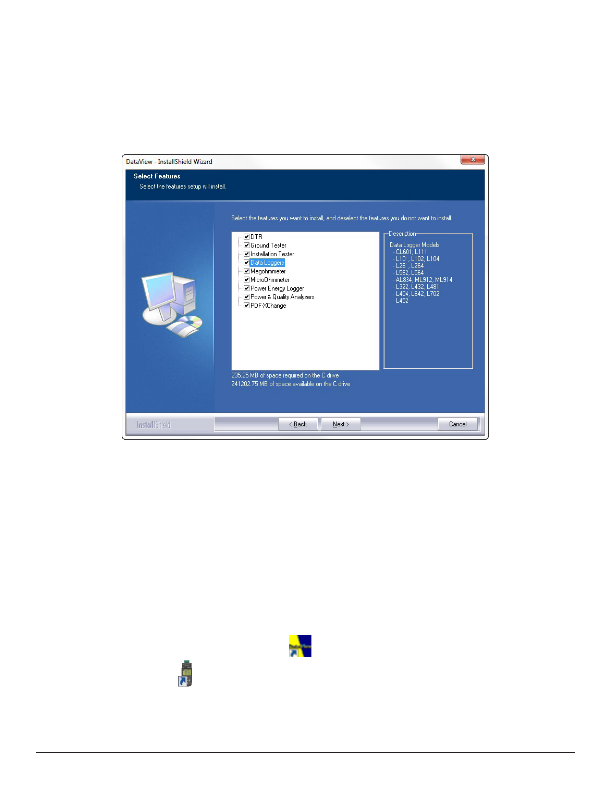
The InstallShield Wizard program leads you through the DataView installation process. To proceed, click Next.
5. Read the license agreement and indicate your acceptance by clicking “I accept the terms of the license agreement.” Then click
Next.
6. At the Customer Information screen, enter your username and company name. Also choose whether this installation is for all
users of the computer, or just for your username. Click Next to proceed.
7. The next screen lets you select the DataView setup. If you choose Custom, you are prompted to select individual DataView
components to install. To install the full DataView product, select Complete and then click Next.
8. You are now prompted to select the Control Panel(s) you want to install.
Figure 41. Select Features screen
As we mentioned earlier, each AEMC product family has its own specially designed Control Panel. By default, all available
Control Panels are selected. Control Panels take up disk space on the computer, so unless you have other types of AEMC
instruments, we recommend that you select Data Logger and deselect the rest. You should also check the option PDFXChange, which is a requirement if you plan to create .pdf versions of DataView reports.
After you nish selecting and deselecting Control Panels, click Next.
9. The InstallShield Wizard now informs you that the program is ready to install DataView. If you want to review any of your
previous selections, click the Back button to return to earlier screens. Otherwise, click Install to begin installation.
10. The InstallShield Wizard now installs DataView. During this process, a status bar displays the progress of the installation.
During installation, you may see a warning message about installing DataView with your AEMC instrument connected to the
computer. If the instrument or USB cable is connected, disconnect it now. Then click OK to proceed.
11. After a few moments, a screen appears informing you that installation is complete. Click Finish to leave the InstallShield
Wizard. You are now asked whether or not you would like to view instructions about how to connect the AEMC instrument or
cable to the USB port on the computer. Click Yes to view these instructions, or No to proceed.
12. Close the DataView Setup screen. The DataView icon now appears on your computer desktop, along with the Data
Logger Control Panel icon and the icon(s) for any other Control Panel(s) you have installed.
36
Data Logger Model L452
Page 39

6.2 The Data Logger Control Panel
After you install DataView, the DataView icon appears on your desktop. This opens the core DataView program. The installation process
also places the Data Logger Control Panel icon on your desktop. Clicking this icon opens the Data Logger Control Panel.
Figure 42. Data Logger Control Panel (instrument connected)
In general, core DataView features are for creating, viewing, editing, and storing DataView reports; while the Control Panel is for connecting to, conguring, viewing real-time measurements, and downloading data from the Model L452. You can access all DataView features
through either the DataView icon or the Control Panel icon. For users who interact with a single type of AEMC instrument, we recommend
primarily using the Control Panel. However, there are situations where using the core DataView icon may be more convenient for some
users, such as when viewing multiple archived reports from dierent AEMC product families.
For further information about DataView and its capabilities, or for information about using the Data Logger Control Panel, consult the Help
system that comes with the product. Access this Help by clicking the option Help in the Control Panel’s menu bar at the top of the screen.
6.3 Connecting the Model L452 to the Computer
Before you can use the Data Logger Control Panel to communicate with your Model L452, you must establish a connection between the
instrument and the computer running DataView. There are two types of connections available:
■ Direct physical connection between the instrument and the computer, through a USB cable
■ Bluetooth wireless connection
To begin, ensure that you have installed DataView, and selected the Data Logger Control Panel during the installation process. Also
ensure that the required communication and connection drivers are installed on your computer. These drivers are installed as part of the
DataView installation process.
Data Logger Model L452
37
Page 40

6.3.1 USB Connection
USB is typically used for connecting a single local instrument. When you purchase the Model L452, a USB cable comes as part of the
product package. To begin the connection process:
1. Plug one end of the cable into the instrument, and the other end into an available USB port on the computer. The instrument
will automatically turn ON. If this is the rst time this instrument has been connected to this computer, the drivers will be
installed. Wait for driver installation to nish before proceeding to the next step.
2. With the Model L452 connected, open the Data Logger Control Panel (see Figure 42).
3. In the menu bar at the top of the screen, select Help. In the drop-down menu that appears, click the option Help Topics. This
opens the Data Logger Control Panel Help system.
4. Use the Contents window in the Help system to locate and open the topic “Connecting to an Instrument.” This topic provides
instructions explaining how to connect your Model L452 to the computer.
After the instrument is successfully connected, consult the Data Logger Control Panel Help system for instructions about viewing real-time
data on the instrument, downloading and viewing recorded sessions, creating DataView reports from the downloaded data, and congur-
ing the instrument through the Control Panel.
6.3.2 Bluetooth Connection
Bluetooth is a standard for wirelessly connecting devices over short distances. This is especially useful for connecting multiple local
instruments to a computer, since unlike USB it does not require a physical connection port for each instrument. The Model L452 includes
built-in Bluetooth capability.
To use Bluetooth to connect to a computer, Bluetooth must be enabled on the instrument, as explained in § 3.1.3. Your computer must
also be Bluetooth-enabled. Some computers have Bluetooth connectivity built in, while others require a Bluetooth-USB adapter. When
this adapter is plugged into a USB port and congured with the appropriate driver, the computer can communicate via Bluetooth.
When the computer is Bluetooth-ready, you can connect to the Model L452 as follows:
1. Open the Bluetooth Devices dialog on your computer to pair the instrument with your computer. Dierent operating systems
have dierent steps for opening this dialog, so consult your computer’s documentation for instructions.
2. Once the dialog is displayed, click Add a Device. A dialog box appears listing the locally available Bluetooth devices. There
may be several devices of varying types listed, depending on the location of your computer.
Find the L452 instrument, which will appear listed by its Bluetooth name as displayed in the L452’s Bluetooth Name screen
(see Figure 8). If the name does not appear, check the Bluetooth Enabled/Visibility screen (Figure 7) on the L452 to ensure
the Visibility eld is set to Visible. If the name is visible, click it. You are prompted to enter a pairing code, which for L452
instruments is always 0000.
3. After you enter the code, click Next. A screen appears informing you that the instrument has been successfully connected with
the computer. Click Close to exit the screen.
4. To complete the connection, open the Data Logger Control Panel. In the menu bar at the top of the screen, select Help. In the
drop-down menu that appears, click the option Help Topics. This opens the Data Logger Control Panel Help system.
5. Use the Contents window in the Help system to locate and open the topic “Connecting to an Instrument.” This topic provides
instructions explaining how to connect your Model L452 to the computer.
After the L452 is successfully connected, consult the Data Logger Control Panel Help system for instructions about viewing real-time
data, downloading and viewing recorded sessions, creating DataView reports from the downloaded data, and conguring the instrument
through the Control Panel.
38
Data Logger Model L452
Page 41

7. SPECIFICATIONS
7.1 Reference Conditions
Inuencing Parameters Reference values
Temperature 20 ± 3 °C
Relative humidity 45 to 55%RH
Internal supply voltage 2.4 ± 0.2V
External supply voltage 110 to 240V 50/60Hz
Electric eld < 1V/m
Magnetic eld < 40A/m
7.2 Electrical
7.2.1 Input Types
Input type
DC voltage
DC current 4 to 20mA 0.01mA ±(0.25% + 5cts) 100Ω 5 samples/second
Pulse* ±10V n/a n/a n/a 100 samples/second
Event ±10V n/a n/a 1MΩ 16 samples/second n/a
*The L452 accepts pulse input from Dry-Contact, Normally Open, and Normally Closed contacts. Typically, a pulse is dened as a change
from the “normal” state that lasts at least 30ms, followed by a return to normal that lasts at least 30ms. Note that using Normally Closed
sensors can signicantly reduce the battery charge life compared to using Normally Open inputs. Output voltage for the pulse input: 3.3V
(with 1MW pull-up resistor).
Measurement
Range
±100mV 0.1mV ±(0.5% + 1 cts) 1MΩ 5 samples/second
±1V 1mV ±(0.5% + 1 cts) 1MΩ 5 samples/second
±10V 10mV ±(0.5% + 1 cts) 1MΩ 5 samples/second
Resolution Accuracy
Input
Impedance
Max Sample Rate Sample Period
200, 400, 600, or 800ms;
or from 1 to 60 seconds
200, 400, 600, or 800ms;
or from 1 to 60 seconds
200, 400, 600, or 800ms;
or from 1 to 60 seconds
200, 400, 600, or 800ms;
or from 1 to 60 seconds
200, 400, 600, or 800ms;
or from 1 to 60 seconds
7.2.2 Power Supply
Parameter Value
Power source
Maximum 2.5W (running on USB power while charging)
Consumption / Life
(with Bluetooth deactivated)
Pulse output voltage 3.3V
Electromagnetic compatibility
● External power supply (110 to 240V, 50/60Hz), via a USB cable
● Rechargeable batteries (2 x 1.2V 2400mAh NiMH)
Sampling rate: 200ms 400ms 60s
Screen lit: 6mA / 18 days 5mA / 21 days 4mA / 27 days
Screen o: 3mA / 36 days 2mA / 54 days 0.4mA / 270 days
Immunity complies with IEC 61326-1:Ed1 and IEC 61326-2-2:Ed1, emissions complies
with IEC 61326-1:Ed1 and IEC 61326-2-2:Ed1 for class A equipment
When the instrument is o (and not on standby), pressing the Power button displays the remaining capacity of the batteries.
To save the batteries, the instrument switches to standby at the end of 20 minutes with no key press. This does not prevent the instrument
from continuing to make measurements. Simply press the Power button to switch it back to full on.
Data Logger Model L452
39
Page 42

7.3 Recording and Data Storage
■ Data storage: 32MB internal memory (up to 1024 recording sessions, 16M samples)
■ Recording mode: Start/Stop (ends when memory is full or when the recording stop time is reached, whichever comes rst)
7.4 Communication
Bluetooth 2.1, Class 1
■ Range: 100m (328 ft) line-of-sight
■ Default pairing code: 0000
■ Nominal output power: +15dBm
■ Nominal sensitivity: -82dBm
■ Rate: 115Kbits/s
USB 2.0
7.5 Mechanical
Parameter Value
Weight (with batteries) Approximately 200g (7oz)
Dimensions
LCD 128 by 64 pixels
Inputs 6-pin screw terminal strip providing two separate input channels
Drop test Per IEC 61010-1
65.5mm (2.58”) wide by 32.4mm (1.28”) thick by 125mm (4.92”) in length (137.5mm [5.41”] with screw
terminal connector installed)
7.6 Environmental
Parameter Value
Temperature
Humidity
Altitude
Operating temperature: 0 to 50°C (32 to 122°F)
Storage temperature: with battery -20 to 50°C (-4 to 122°F), without battery: -20 to 65°C (32 to 149°F)
Operating humidity: 10 to 85% (at temperature 0 to 40°C [32 to 104°F]), 10 to 50% (at temperature 40 to
50°C [104 to 122°F])
Storage humidity:
- With battery: 0 to 90% (at temperature -20 to 40°C [-4 to 104°F]), 0 to 50%
(at temperature 40 to 50°C [104 to 122°F])
- Without battery: 0 to 90% (at temperature -20 to 40°C [-4 to 104°F]), 0 to 50%
(at temperature 40 to 65°C [104 to 149°F])
Operating altitude: 0 to 2000m (0 to 6562 ft)
Storage altitude: 0 to 10000m (0 to 32800 ft)
7.7 Safety
■ Ingress protection: IP40 per IEC 60 529
IK 04 per IEC 50102
■ Electrical safety: IEC 61010-1 Ed3 and IEC 61010-2-030:Ed1
40
Data Logger Model L452
Page 43

8. MAINTENANCE AND TROUBLESHOOTING
MEMORY:
NO ACTION
MIN/MAX:
NO ACTION
The Data Logger Model L452 is designed for easy and trouble-free use. There are, however, a few simple maintenance tasks you should
perform periodically to ensure optimal operation. In addition, your L452 may exhibit unexpected behavior that requires troubleshooting.
This chapter explains procedures you can perform to maintain the L452 and troubleshoot issues you may encounter.
8.1 Model L452 Maintenance
There are a number of routine maintenance tasks you will need to perform to ensure your Model L452 operates normally. These include:
■ Erasing the instrument’s memory
■ Upgrading to the latest rmware revision
■ Replacing the instrument’s batteries
■ Cleaning the instrument
The following sections explain how to perform these tasks.
8.1.1 Erasing Memory
The L452 comes with approximately 32MB of memory for storing recording sessions. The Memory icon in the top right corner of the LCD
provides a rough estimate of how much of this memory has been used, and how much remains free and available for future recording sessions. When the Memory icon appears lled in this indicates there is little or no free memory left in the instrument. Memory is full when
either (1) the stored recording sessions consume all available memory, or (2) there are 1024 recording sessions stored in the instrument.
The Recording Sessions screen (Figure 20) shows both the number of recording sessions currently stored in memory, and the amount of
free memory remaining for additional sessions. When memory is full, you cannot start a recording session.
Note that the memory erase process removes all stored recording sessions. You cannot selectively erase some sessions while saving
others on the instrument. If you need to save one or more recording sessions, you must download them to a computer using the DataView
Data Logger Control Panel (see § 6).
You can clear memory through either the Data Logger Control Panel, or via the Model L452 user interface. To use the instrument’s inter-
face to clear memory, do the following:
1. At the Channel 1 & 2 Measurement Data screen (Figure 4), press ► four times to display the Language and Date/Time Format
screen (Figure 5). This is the top-level screen for instrument conguration.
2. Press ▼. This displays the Memory and Min/Max screen.
Figure 43. Memory and Min/Max screen
3. Press to initiate selection mode, then press again to begin edit mode.
4. Use the ▲ and ▼ buttons to toggle between the choices No Action and Erase. When Erase is displayed, press to accept
the selection.
5. A screen appears asking you to conrm the memory erasure. If you do not want to erase the memory at this time, press ◄ and
► simultaneously. This returns you to the Memory and Min/Max screen without taking further action. To conrm the memory
erasure, press .
6. The L452 begins erasing the memory. During this process, a progress screen appears displaying the amount of memory that
has been erased, and the amount that remains to be erased.
Data Logger Model L452
41
Page 44
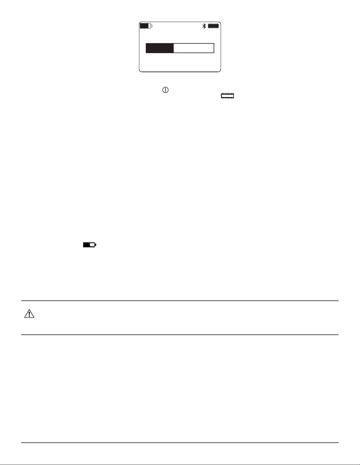
ERASING MEMORY
Figure 44. Erasing Memory screen
During this procedure, all buttons (including Power ) are disabled. When memory has been erased, the Memory and Min/
Max screen returns. The Memory icon will again show full memory available and the Free Memory eld in the Recording
Sessions screen will be 31.88MB (see § 3.4.3).
8.1.2 Upgrading to the Latest Firmware
Periodically AEMC® may update the rmware that runs on the Model 452. This rmware controls the features and functionality of the
instrument.
We recommend checking for rmware upgrades on a regular basis, to ensure your instrument has the most current version. The easiest
way to do this is from the Data Logger Control Panel. The Help menu in the Control Panel includes the option Update. When you click this
option, the Control Panel automatically checks to ensure you have the latest version of the rmware, and displays a message informing
you whether or not your rmware is up to date.
8.1.3 Installing and Replacing the Batteries
The Model L452 can operate on two sources of power:
■ USB cable connected to an external power source, such as a computer
■ Two internal 1.2V AA 2400mAh NiMH batteries
You must insert the batteries into the instrument before use, even if you plan to run the instrument on USB power. When operating on
battery power, the Battery icon indicates how much electric charge remains in the batteries. The solid ll portion of the icon corre-
sponds to the percentage of remaining power. You can charge the battery by plugging the USB cable into the instrument and connecting
it to a computer or the USB-compatible wall adapter that comes as part of the standard Model L452 product package. When the battery
is charging, the solid ll portion of the icon repeatedly moves from the completely discharged level to the completely full level.
There may be times when you need to change the batteries in the instrument. For example, you may want to charge the batteries in a
separate external charger, and replace them with fresh batteries. You may also need to replace batteries that can no longer hold a charge.
When replacing batteries, always replace both at the same time.
Disconnect all sensors, probes, USB cable, or other connections before opening the rear cover to change the batteries. Also be
sure the Model L452 is turned OFF before changing the batteries, otherwise you may lose recorded data.
Only use NiMH batteries. Using any other batteries may damage the instrument.
To install or replace the batteries, do the following:
1. Holding the instrument rmly, slide the back cover to the right.
2. Lift the back cover o the instrument.
3. If the instrument does not already have batteries installed, skip this step and go to step 4 below. If you are replacing existing
batteries, remove them now.
4. Insert the two fresh batteries, ensuring the positive and negative ends are properly aligned.
5. Replace the back cover by aligning the tabs in the cover with the corresponding slots in the instrument body, and then sliding
the cover to the left until it locks in place.
Note that if the Model L452 is stored without the batteries installed, its internal clock will need to be reset. See § 3.1.2 for instructions about
how to set the instrument’s date and time.
42
Data Logger Model L452
Page 45

8.1.4 Cleaning the Instrument
The Model L452 should be cleaned periodically. This keeps the LCD clear and easily viewable, and also prevents dirt and grease buildup
around the instrument’s front panel buttons and input terminals.
Before cleaning, disconnect all input(s) to prevent possible electric shock.
The body of the instrument should be cleaned with a damp and soapy cloth. Do not submerge the instrument in water. Do not use solvent.
8.2 Troubleshooting the Model L452
This section describes how to correct several potential issues you may encounter while operating the L452. These include:
■ The Model L452 does not turn ON when you press the Power button.
■ The instrument turns ON but does not function.
■ The Overload icon appears in the instrument’s icon bar.
■ You cannot congure through the instrument’s interface.
■ You cannot set up or start a recording session on the instrument.
■ Recording sessions end before the specied end date and time.
■ You cannot connect to a computer.
■ The instrument does not turn OFF when you press .
The following sections explain some of the possible causes for these issues and how you can address them. If you perform these troubleshooting actions but the issue still persists, or if you encounter a problem not covered in this section, please contact AEMC Technical
Support.
8.2.1 L452 Does Not Turn ON
To turn ON the Model L452, press for at least two seconds, until the words POWER ON appear in the LCD. After a short power-up
sequence, the Channels 1 & 2 Measurement Data screen appears on the instrument’s LCD.
If pressing does not turn ON the instrument, ensure that you are holding down this button the required two seconds. If you do so and
the instrument still does not turn ON, the batteries may need to be charged. Plug the USB cable into a computer or the USB power adapter
that is included as part of the L452 product package.
If after charging the batteries fail to maintain power, replace them as described in § 8.1.3.
If you are running the instrument on power supplied by the USB cable, unplug the cable and remove the batteries. (This resets the instru-
ment.) Then replace the batteries, plug in the USB cable, and press .
Note that after 20 minutes of inactivity, the LCD screen will go blank. (This is a screen saver feature.) While in this state, the instrument
may appear to be OFF. A short press of restores the display.
8.2.2 L452 Turns ON But Does Not Function
If the Model L452 has been stored in a cold and damp environment, condensation may form inside the instrument. This condensation can
short the circuitry, preventing the instrument from operating normally. In this case, turn OFF the Model L452 and place it in a warm, dry
environment for several hours. Then turn the instrument ON and try navigating through the screen interface to determine whether or not
it has been restored to normal function.
If the instrument is operating on USB power, reset the instrument by unplugging the cable and removing the batteries. Replace the batteries, plug in the USB cable, turn ON the instrument, and then attempt to navigate the screens.
Data Logger Model L452
43
Page 46

8.2.3 Overload (OL) Icon is Displayed
The Overload icon in the icon bar indicates that the input is out of range for the selected input type and cannot be displayed. To correct
this, go to the Channel Enable/Disable screen (Figure 9) and ensure that the selected input type matches the output from the connected
probe. If not, change the input type to the appropriate setting. (See also § 3.2.2.)
If the Overload icon continues to ash no matter which setting you choose, the connected probe or sensor may be unsupported for use
with the Model L452. Replace the probe or sensor with one that generates a compatible output for the input type selected on the instru-
ment.
8.2.4 Cannot Congure the L452
Several conditions may cause some or all of the conguration options to appear disabled, or function in unexpected ways. For example,
when the instrument is in Remote mode and under the control of the Data Logger Control Panel, none of the conguration options is
enabled; you cannot change or view any conguration setting from the instrument interface. The only screens that operate are ones that
display measurement data.
Remote mode is initiated when the instrument is connected to the computer. It can also be set through the “Lock out instrument front panel
conguration” option in the DataView Data Logger Control Panel. When this option is selected, the instrument remains in Remote mode
even when it is disconnected from the computer.
To leave Remote mode and return local control, ensure the “Lock out instrument front panel conguration” option is deselected. The
DataView Data Logger Control Panel Help explains how to do this. Then disconnect the instrument from the Data Logger Control Panel.
Another option (not recommended due to potential loss of data) is to turn OFF the instrument. To do this, press and hold down . After
approximately two seconds, the words REMOTE MODE appear on the screen. Continue to hold down until the words POWER OFF
appear. Release the button; the instrument is now turned OFF. When you turn it back ON, it will be in Local mode.
Similarly, most conguration options are unavailable when the instrument is actively recording data, or when a recording session is
scheduled. In either case, the only active conguration option is to stop the recording (if one is active) or cancel the recording (if one is
scheduled). Stopping or canceling the recording, as instructed in § 5.6, returns the conguration options to full functionality.
If some conguration screens are active, while others are inactive (or don’t appear at all), you may have the wrong input type selected.
Input settings can aect which conguration screens are available. For example, if you select Pulse as the input type, the conguration
screens for conguring alarm triggers do not appear. If a conguration screen that you expect to be available does not display, check the
input type to ensure it is set correctly, and if not change it as required. Bear in mind that both channels must have the same input type;
changing the input type for one channel automatically sets the other channel to the same input type. (See also § 3.2.2.)
8.2.5 Cannot Congure a Recording Session
If you attempt to start or schedule a recording but cannot do so, the Model L452 may be in Remote mode. As mentioned earlier, all conguration options are disabled on the Model L452 while the instrument is in Remote mode. § 8.2.4 explains how to leave Remote mode
and return local control to the instrument.
In addition, the options for setting up and starting/scheduling a recording are disabled when a recording is already in progress or scheduled. Check to see whether or not the Recording icon appears in the icon bar. If the icon appears a recording is in progress; if the
icon appears a recording is scheduled. To enable recording features, stop or cancel the recording per the instructions in § 5.6.
8.2.6 Recording Sessions Do Not Start
Recording sessions are stored in memory. When you congure a recording session, the instrument automatically checks to ensure there
is sucient space in its memory to store the session’s expected data. If not, the recording session does not start. To free up memory for
the recording session, follow the instructions contained in § 8.1.1. Note that this process erases the entire instrument memory; you cannot
selectively erase some recording sessions while leaving others. Any sessions you want to save need to be downloaded to a computer.
Another condition that could prevent a recording session from starting is if the start and/or end times and dates are congured incorrectly,
such as a stop date/time that has already passed. If the instrument has sucient memory for the recording but it still will not start, check
the recording’s start and stop times/dates to ensure they are congured properly.
See § 5 for information about conguring a recording session.
44
Data Logger Model L452
Page 47

8.2.7 Recording Sessions End Prematurely
If a recording session terminates before its scheduled stop time, a likely cause is that the instrument’s memory has become full. When
this happens, the Memory icon appears lled. To free up memory, follow the instructions contained in § 8.1.1.
In addition, a recording session terminates, and the instrument turns OFF, if the voltage in the instrument’s batteries falls below 2.1V. If
this happens, recharge the batteries.
8.2.8 Cannot Connect to a Computer
If you cannot connect the Model L452 to the computer via Bluetooth, ensure that Bluetooth is enabled on the instrument, as instructed by
§ 3.1.3. If Bluetooth is enabled but you cannot connect the instrument via the Data Logger Control Panel – for example, the L452 does
not appear as available when you attempt to connect with it – the instrument may not be paired with the computer. Dierent computers
and operating systems have dierent processes for pairing Bluetooth devices; consult the documentation that comes with your computer
for instructions about how to do this.
Battery voltage also aects Bluetooth availability. If battery voltage falls below 2.2V, the Bluetooth radio in the Model L452 turns OFF and
the Bluetooth icon disappears from the LCD. The instrument will otherwise continue to function normally. Verify that Bluetooth is enabled.
If it is, and the Bluetooth icon is not displayed, the battery voltage has fallen below 2.2V at some point. Note that the voltage may recover
somewhat and rise slightly above 2.2V after the Bluetooth radio is disabled. However, you must charge the batteries to full voltage to
restore full Bluetooth functionality.
Finally, check whether or not the instrument is already connected to DataView. The Control Panel only allows one connection per instrument. For example, if you have already established a connection to the instrument via USB, you will not be able to create a second connection via Bluetooth. This is true even if the instrument is not actively connected to and communicating with the computer.
8.2.9 Cannot Turn OFF the Model L452
Turning OFF the Model L452 requires pressing and holding down for two seconds. A press shorter than two seconds does not turn
o the instrument; instead it displays the Channel 1 & 2 Measurement Data screen. If pressing does not turn OFF the instrument, be
sure you are holding down the button for the required two seconds.
Remote mode has an eect on how the button functions. If you press and hold down while in Remote mode, after two seconds the
message REMOTE MODE appears on the screen. To turn OFF the instrument, you must continue to hold down for an additional two
seconds until the words POWER OFF appear.
In addition, you cannot turn OFF the L452 if a recording session is active. Note that you can turn OFF the Model L452 if a recording is
scheduled but not currently in progress. However, if the instrument is OFF when the recording’s start date and time is reached, the Model
L452 will automatically turn back ON and begin the recording.
If after you perform the preceding checks the instrument still does not turn OFF, unplug the USB cable (if connected) and remove the
batteries. (This should only be done as a nal step since it could result in loss of data.)
Data Logger Model L452
45
Page 48
APPENDIX A. USER INTERFACE SCREENS
As explained in § 2.3.1, the primary interface for working with the L452 consists of conguration and display screens. These screens
appear in the instrument’s front-panel LCD. The instrument’s buttons enable you to navigate these screens, select options, and enter
information.
Screens are grouped into six categories:
■ Measurement Data screens display data currently being measured on Channel 1 and/or Channel 2.
■ Recording screens congure, start, schedule, stop, and cancel a recording session.
■ Channel 1 Conguration screens enables/disables Channel 1 and determines what data is recorded by the channel and how
it is displayed.
■ Channel 2 Conguration screens are identical to Channel 1 Conguration screens, except they apply to the instrument’s
Channel 2.
■ Instrument Conguration screens congure general instrument settings.
■ Instrument Information screens display read-only settings on the instrument.
Each category has a “top level” screen; this is the rst screen that appears when you move to the category. The following table is a graphi-
cal representation for how these categories and screens are organized.
Measurement Data Recording
Channels 1 & 2
Measurement Data
(Home screen)
Channel 1 Measurement and Min/
Max Data
Channel 2 Mea-
surement and Min/
Max Data
*Not displayed when input is set to Event.
**Not displayed when input is set to Event or Pulse.
Start/Stop/Schedule/Cancel a
Recording, and Set
Duration
Sample Period and
Storage Period
Start Date and Time **Low Scaling **Low Scaling Conguration Reset
Stop Date and Time **High Scaling **High Scaling Date and Time Recording Name
Channel 1
Conguration
Enabled/Disabled
and Input Type
*Units *Units
**Alarm Trigger **Alarm Trigger
**Upper Limit and
Lower Limit
Equivalence
(Pulse Input Only)
Trigger (Event Input
Only)
Channel 2
Conguration
Enabled/Disabled
and Input Type
**Upper Limit and
Lower Limit
Equivalence
(Pulse Input Only)
Trigger (Event Input
Only)
Instrument
Conguration
Language and Date/
Time Format
Memory Erase and
Min/Max Reset
Bluetooth Enable/
Disable and Visibility
Bluetooth Name
Instrument
Information
Model Number,
Serial Number,
and Firmware
Revision
Instrument Name
and Location
Recording Sessions
As noted above, several of these screens are conditional and only appear when certain input types are selected. For instance, scaling
screens only appear for analog input (voltage and current); the Equivalence screen only appears when the input type is Pulse; and so on.
Pressing the ► or ◄ button while in navigation mode moves from one category of screens to the next. These buttons work from any
screen in a category. For example, pressing ► from any of the three Measurement Data screens displays the top-level Recording screen.
The categories are “cyclical,” pressing ► at an Instrument Information screen moves to the top-level screen in Measurement Data, while
pressing ◄ in a Measurement Data screen displays the top-level Instrument Information screen. The ▲ and ▼ buttons let you navigate
the screens within each category. These are also cyclical; pressing ▲ in a category’s top-level screen displays the bottom level screen in
that category, while pressing ▼ at the bottom-level screen displays the category’s top-level screen.
46
Data Logger Model L452
Page 49

For example, when you rst turn ON the L452, the rst screen that appears is the top-level Measurement Data screen displaying measurement data for both channels 1 and 2. This is the instrument’s Home screen. Suppose you want to view the minimum and maximum
data for channel 2. Referring to the preceding table, we see that this is two levels “below” the Channel 1 & 2 Measurement Data screen.
So to navigate to this screen, press ▼ twice. Now suppose you want to reset the minimum/maximum values. As shown in the preceding
table, this screen is in the Instrument Conguration category. To navigate to this category, press ► four times. This displays the top-level
Instrument Conguration screen (Language and Date/Time Format). Then press ▼ to display the Memory Erase and Min/Max Reset
screen.
The following sections list the screens for each category.
A.1 Measurement Data Screens
These screens display measurement data and minimum/maximum values for data currently being measured. For instructions about viewing measurement data, see § 4.
Use the ▲ and ▼ buttons to navigate through these screens. Note that pressing ► from any of these screens displays the top-level
Recording screen (see § A.2) while pressing ◄ displays the top-level Instrument Information screen (see § A.5).
Measurement Data Screen Description Comments
Channels 1 & 2 Measurement Data
(Home screen)
(Analog input shown)
Channel 1 Measurement and Min/
Max Data
(Analog input shown)
Measurement data currently being
measured on both channels 1 and 2.
For analog input: The average sample
value measured by channel 1 over the
last completed storage period, and the
minimum and maximum values since
the last min/max reset.
For pulse input: the maximum number
of units that have been measured on
channel 1 during a storage period
since the last min/max reset, and the
date and time of the storage period
with the maximum value.
For event input: an image of the last
completed second in which an event
occurred on channel 1, and the date
and time for the event.
This is the rst screen displayed when you turn ON
the L452 and the instrument completes its power-up
sequence.
You can return to this screen from any other screen
by giving a short press.
Pressing▼ displays the Channel 1 Measurement
and Min/Max Data screen. Pressing ▲ displays the
Channel 2 Measurement and Min/Max Data screen.
The minimum/maximum values are not displayed
when the input type is set to Event.
The minimum value is not displayed when the input
type is set to Pulse.
Pressing ▼ displays the Channel 2 Measurement
and Min/Max Data screen. Pressing ▲ displays the
Channels 1 & 2 Measurement Data (Home) screen.
Data Logger Model L452
47
Page 50

Channel 2 Measurement and Min/
Max Data
For analog input: The average sample
value measured by channel 2 over the
last completed storage period, and the
minimum and maximum values since
the last min/max reset.
The minimum/maximum values are not displayed
when the input type is set to Event.
The minimum value is not displayed when the input
type is set to Pulse.
(Pulse input shown)
For pulse input: the maximum number
of units that have been measured on
channel 2 during a storage period
since the last min/max reset, and the
date and time of the storage period
with the maximum value.
For event input: an image of the last
completed second in which an event
occurred on channel 2, and the date
and time for the event.
Pressing ▼ displays the Channels 1 & 2 Measurement Data screen. Pressing ▲ displays the Channel
1 Measurement and Min/Max Data screen.
A.2 Recording Screens
These screens congure and run a data recording session. This recorded data can then be downloaded to a computer running the Data-
View Data Logger Control Panel for further display and analysis. These screens are not available in Remote mode. For instructions about
how to set up and run a recording session, see § 5.
Pressing ► from any of these screens displays the top-level Channel 1 Conguration screen (see § A.3) while pressing ◄ displays the
top-level Measurement Data screen (see § A.1).
Recording Screen Description Comments
Start/Stop/Schedule/Cancel a
Recording, and Set Duration
Start a recording immediately, schedule a future recording, set the duration
for a recording, stop an active recording, cancel a scheduled recording.
This screen is conditional. If a recording is in progress, the only available option is Stop. If a recording
is scheduled, the only available option is Cancel.
Changing the Duration setting overrides any previ-
ously set Stop Date/Time setting.
(Screen shown as it appears when
no recording is currently in progress
or scheduled)
Sample Period and Storage Period Sets the sample and storage periods
for the recording session.
Start Date and Time Sets the start date and time for a
scheduled recording session.
Pressing ▼ displays the Sample Period and Storage Period screen. Pressing ▲ displays the Stop
Date and Time screen.
This screen is disabled if a recording is active or
one has been scheduled.
For Event input, this screen is display-only. The
Sample Period eld is set to 62.5ms and the Storage Period eld is set to 1s.
Pressing ▼ displays the Start Date and Time
screen. Pressing ▲ displays the Start/Stop/Sched-
ule/Cancel a Recording, and Set Duration screen.
This screen is disabled if a recording is active or
one has been scheduled.
Pressing ▼ displays the Stop Date and Time
screen. Pressing ▲ displays the Sample Period and
Storage Period screen.
48
Data Logger Model L452
Page 51
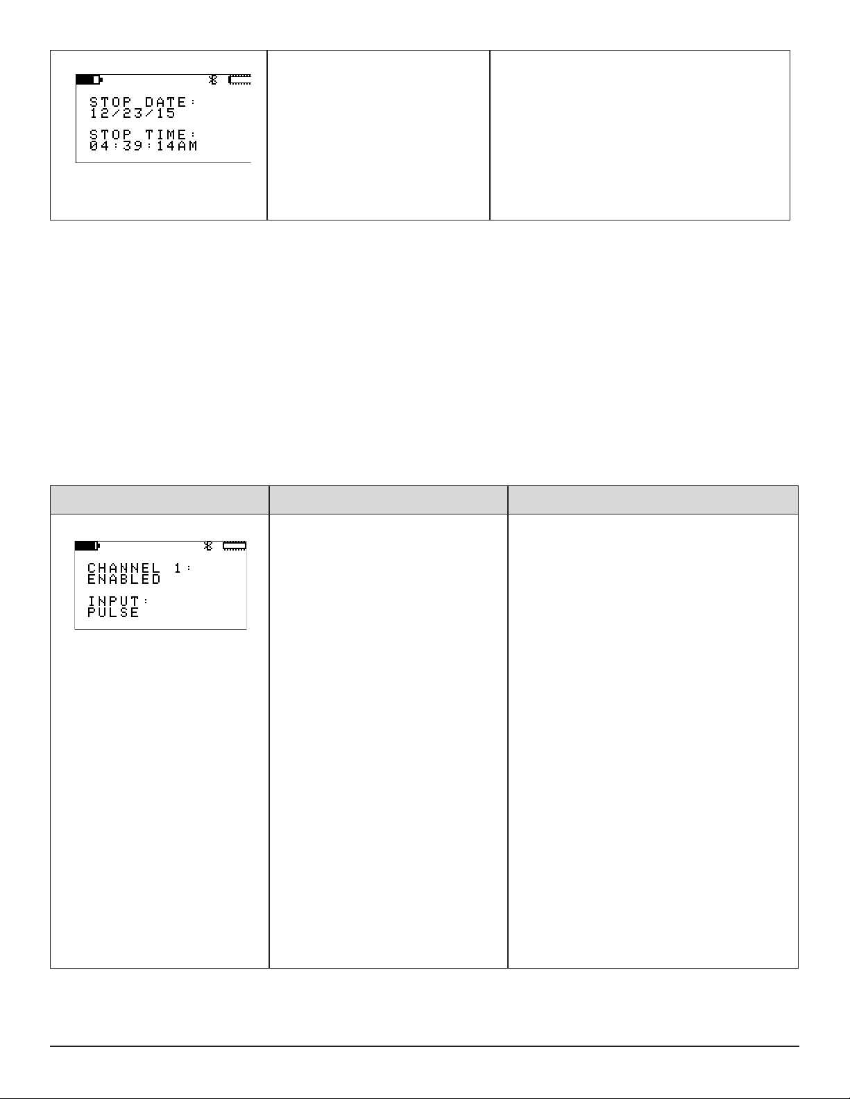
Stop Date and Time Sets the stop date and time for a
scheduled recording session.
This screen is disabled if a recording is active or
one has been scheduled.
If you set this after you set the Duration (see
above), the Stop Date and Time settings adjust the
Duration setting.
Pressing ▼ displays the Start/Stop/Schedule/
Cancel a Recording, and Set Duration screen.
Pressing ▲ displays the Start Date and Time
screen.
A.3 Channel 1 and Channel 2 Configuration Screens
These screens congure Channel 1 and Channel 2. Each channel has a separate category for its screens; these screens are essentially
identical for both categories. These screens are not available in Remote mode. For instructions about how to congure channels, see §
3.2.
Note that:
■ Pressing ► from any Channel 1 Conguration screen displays the top-level Channel 2 Conguration screen, while pressing ◄
from a Channel 1 Conguration displays the top-level Recording screen (see § A.2).
■ Pressing ► from any Channel 2 Conguration screen displays the top-level Instrument Conguration screen (see § A.4), while
pressing ◄ from a Channel 2 Conguration displays the top-level Channel 1 Conguration screen.
The following table shows the screens for Channel 1.
Channel 1 Conguration Screen
Enabled/Disabled and Input Type Enables and disables data measurement
on channel 1, and sets the input type for
both channels.
Description Comments
A channel must be enabled to include it in a recording session or to display measurement data.
At least one channel must be enabled at all times.
For example, if you disable channel 1 and then
disable channel 2, channel 1 will automatically
become enabled.
The selected input type must be compatible with
the sensor/probe attached to channel 1. Otherwise,
an overload condition may result.
The input type applies to both channels. If you set
the input type one channel, the other channel is
automatically set to the same input type.
Pressing ▼ displays the following:
- Units screen (if the input type is set to
analog [voltage/current] or Pulse)
- Trigger screen (if the input type is set to
Event)
Pressing ▲ displays the following:
- Upper Limit and Lower Limit screen (if the
input type is set to analog)
- Equivalence screen (if the input type is set
to Pulse)
- Trigger screen (if the input type is set to
Event)
Data Logger Model L452
49
Page 52

Units Denes the units in which the measured
input data will be displayed.
Low Scaling Denes the displayed reading when the
input is at a pre-set low value.
Units can be anything you choose, up to a maximum length of four characters.
This screen is only available for analog (voltage
and current) and pulse input. It does not appear
when the input type is set to Event.
Pressing ▼ displays the following:
- Low Scaling screen (if the input type is set
to analog)
- Equivalence screen (if the input type is set
to Pulse)
Pressing ▲ displays the Enabled/Disabled and
Input Type screen.
This screen is only available for analog input.
Pressing ▼ displays the High Scaling screen.
Pressing ▲ displays the Units screen.
High Scaling Denes the displayed reading when the
input is at its maximum value.
Alarm Trigger Enables and disables alarms and denes
the type of alarm trigger.
This screen is only available for analog input.
Pressing ▼ displays the Alarm Trigger screen.
Pressing ▲ displays the Low Scaling screen.
Allowable values are Above Upper, Below Lower,
Within Limits, Outside Limits, and Disabled.
This screen is only available for analog input.
Pressing ▼ displays the Upper Limit and Lower
Limit screen. Pressing ▲ displays the High Scal-
ing screen.
50
Data Logger Model L452
Page 53
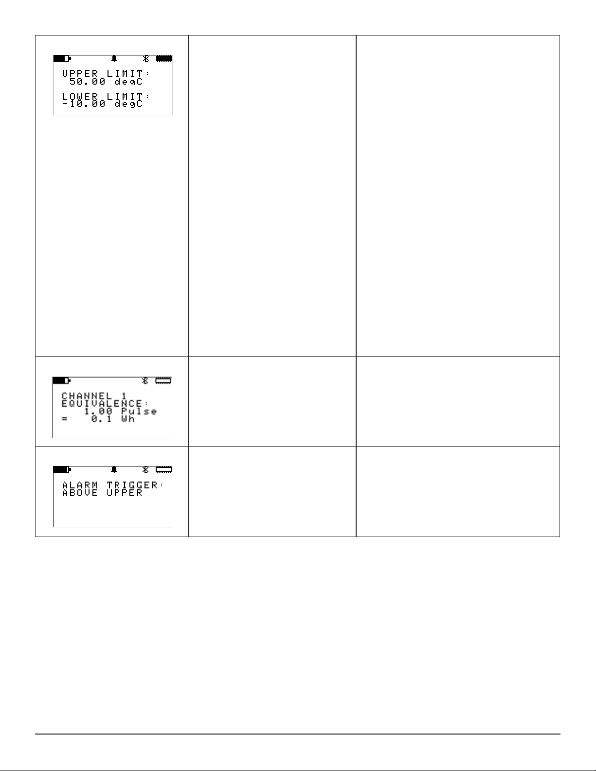
Upper Limit and Lower Limit Denes the upper limit and lower limit for
the alarm trigger.
How this information is used depends on the
alarm trigger setting. For example, if the upper
limit is set to 50°C and the alarm trigger is set to
Above Upper, an alarm is triggered when the measurement exceeds 50°C. If the alarm trigger is set
to Within Limits, an alarm is triggered when the
measurement falls within the range dened by the
Upper Limit and Lower Limit elds.
If the Alarm Trigger eld is set to Within Limits or
Outside Limits, both the Upper Limit and Lower
Limit elds are active. If the alarm trigger is Above
Upper, only the Upper Limit eld is active. If the
alarm trigger is Below Lower, only the Lower Limit
eld is active.
If both elds are active, the Upper Limit eld must
be set to a value higher than the Lower Limit eld.
If you enter an Upper Limit lower than the current
Lower Limit setting, the Lower Limit eld automati-
cally resets to the Upper Limit value. Conversely,
if you enter a Lower Limit higher than the Upper
Limit, the Upper Limit is automatically adjusted to
match the Lower Limit.
This screen is only available for analog input.
Equivalence Denes the relationship between one
pulse and the selected measurement
unit.
Trigger Denes whether an event occurs when
the input goes from low to high (rising) or
when it goes from high to low (falling).
Pressing ▼ displays the Enabled/Disabled and
Input Type screen. Pressing ▲ displays the Alarm
Trigger screen.
This screen is only available for pulse input.
Pressing ▼ displays the Enabled/Disabled and
Input Type screen. Pressing ▲ displays the Units
screen.
This screen is only available for event input.
Pressing either ▲ or ▼ displays the Enabled/Dis-
abled and Input Type screen.
Data Logger Model L452
51
Page 54
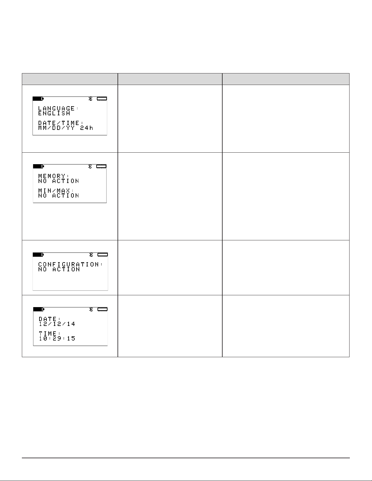
A.4 Instrument Configuration Screens
These screens congure general settings that apply to the instrument. These screens are not available in Remote mode. For instructions
about setting instrument conguration settings, see § 3.
Pressing ► from any of these screens displays the top-level Instrument Information screen (see § A.5) while pressing ◄ displays the
top-level Channel 2 Conguration Information screen (see § A.3).
Instrument Conguration Screen Description Comments
Language and Date/Time Format Sets the language in which the text in
the user interface appears, and denes
the date and time formats.
Memory Erase and Min/Max Reset Erases recording memory, and resets
the minimum and maximum values to
zero.
Available language options are English, Español,
Italiano, Deutsch, and Français.
Available date/time formats are MM/DD/YY AM/
PM, MM/DD/YY 24h, DD/MM/YY AM/PM, and
DD/MM/YY 24h.
Pressing ▼ displays the Memory Erase and Min/
Max Reset screen. Pressing ▲ displays the Bluetooth Name screen.
Erasing memory ensures that sucient space is
available for storing recording sessions (see also
§ 8.1.1).
The Memory option erases all the contents of
memory; you cannot selectively erase some
recording sessions while leaving others intact. To
save a recording session, you must download it to
a computer running DataView.
Pressing ▼ displays the Conguration Reset
screen. Pressing ▲ displays the Language and
Date/Time Format screen.
Conguration Reset Restores conguration settings in the
instrument to their original “out of the
box” default settings.
Date and Time Sets the instrument date and time The date and time will appear in the format
This process resets all conguration modications
and information input except for date/time informa-
tion.
Pressing ▼ displays the Date and Time screen.
Pressing ▲ displays the Memory Erase and Min/
Max Reset screen.
dened by the Language and Date/Time Format
screen (see above).
Pressing ▼ displays the Bluetooth Enable/Dis-
able and Visibility screen. Pressing ▲ displays the
Conguration Reset screen.
52
Data Logger Model L452
Page 55

Bluetooth Enable/Disable and Vis-
ibility
Bluetooth Name Denes the Bluetooth name of the L452. This is the name under which the L452 will appear
Enables and disables Bluetooth in the
instrument, and determines whether or
not the instrument is visible to other local
Bluetooth devices.
Bluetooth must be enabled to communicate with a
computer wirelessly.
You can choose to make the L452 “invisible” to
local Bluetooth devices to limit access from unauthorized computers.
Disabling Bluetooth when the L452 does not need
to communicate with a computer (for example,
during a long recording session) decreases power
consumption and lengthens the life of the instrument’s batteries.
Pressing ▼ displays the Bluetooth Name screen.
Pressing ▲ displays the Date and Time screen.
in the computer’s list of available Bluetooth
devices.
The Bluetooth name consists of two parts. The
rst part is “L452-“ and cannot be changed. The
second part is editable.
Pressing ▼ displays the Language and Date/Time
Format screen. Pressing ▲ displays the Bluetooth
Enable/Disable and Visibility screen.
A.5 Instrument Information Screens
These screens display general information that applies to the instrument. They are display-only and cannot be modied through the L452
user interface (although some of these settings can be changed through the DataView Data Logger Control Panel). These screens are
not available in Remote mode. For instructions about viewing instrument information, see § 3.4.
Pressing ► from any of these screens displays the top-level Measurement Data screen (see § A.1) while pressing ◄ displays the toplevel Instrument Conguration screen (see § A.4).
Instrument Information Screen Description Comments
Model Number, Serial Number, and
Firmware Revision
Instrument Name and Location The name of the instrument and the
Instrument model and serial numbers,
and the revision number of the installed
rmware.
name of its current location.
Check the rmware revision against the rm-
ware revision available in AEMC’s downloads
web page to ensure you are running the latest
rmware in the instrument (see also § 8.1.2).
Pressing ▼ displays the Instrument Name
and Location screen. Pressing ▲ displays the
Recording Name screen.
By default, the instrument name is the model
number followed by the serial number.
The instrument name and location can be set in
the DataView Data Logger Control Panel.
Pressing ▼ displays the Recording Sessions
screen. Pressing ▲ displays the Model Number,
Serial Number, and Firmware Revision screen.
Data Logger Model L452
53
Page 56
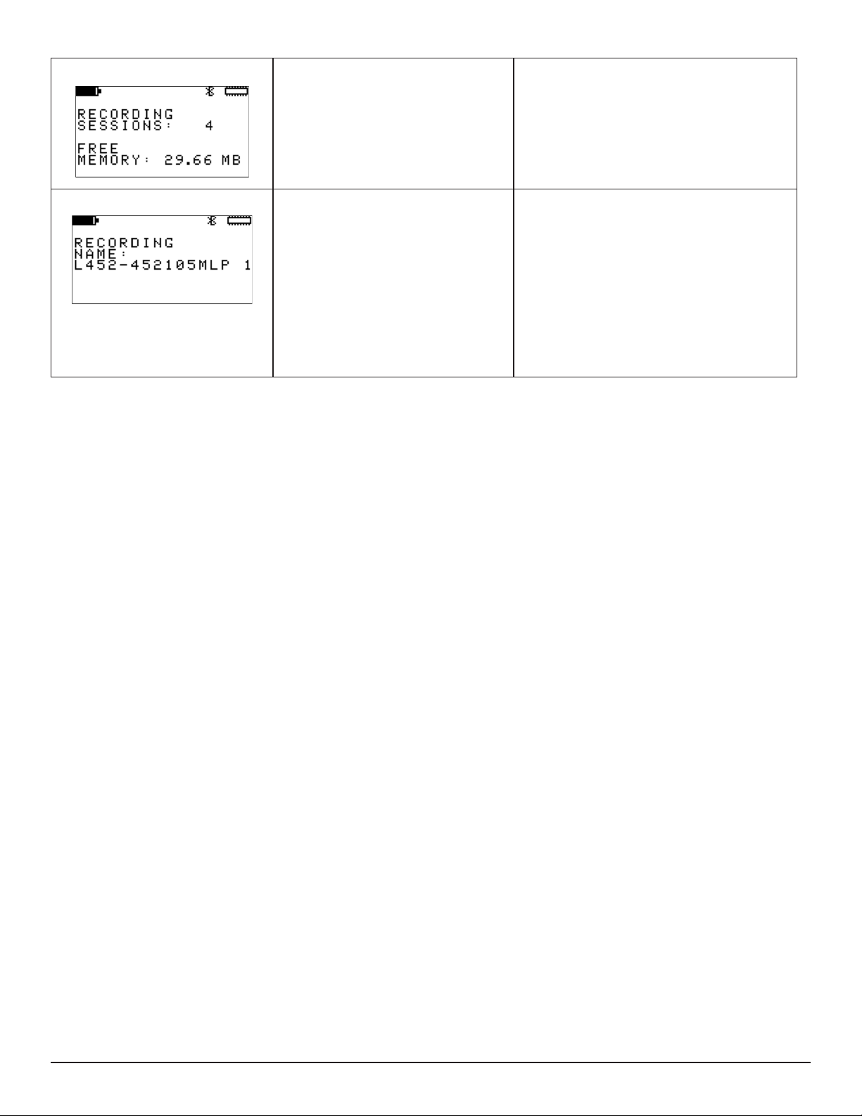
Recording Sessions Displays the number of recording ses-
sions (if any) currently stored in memory,
and the amount of free memory left for
storing additional recording sessions.
This screen appears even if no sessions are
currently stored in the instrument’s memory. In
this case, Free Memory will be 31.88 MB.
Pressing ▼ displays the Recording Name
screen. Pressing ▲ displays the Instrument
Name and Location screen.
Recording Name The name that will be given to the next
recording session stored in memory.
By default, the recording name consists of the
instrument name and a numerical sux that
represents the session number (the number of
sessions currently stored in the instrument plus
one).
The recording name can be changed via the
DataView Data Logger Control Panel.
Pressing ▼ displays the Model Number, Serial
Number, and Firmware Revision screen. Pressing ▲ displays the Recording Sessions screen.
54
Data Logger Model L452
Page 57

REPAIR AND CALIBRATION
To ensure that your instrument meets factory specications, we recommend that it be scheduled back to our factory Service Center at
one-year intervals for recalibration, or as required by other standards or internal procedures.
For instrument repair and calibration:
You must contact our Service Center for a Customer Service Authorization Number (CSA#). This will ensure that when your instrument
arrives, it will be tracked and processed promptly. Please write the CSA# on the outside of the shipping container. If the instrument is
returned for calibration, we need to know if you want a standard calibration, or a calibration traceable to N.I.S.T. (Includes calibration
certicate plus recorded calibration data).
Ship To: Chauvin Arnoux®, Inc. d.b.a. AEMC® Instruments
15 Faraday Drive • Dover, NH 03820 USA
Phone: (800) 945-2362 (Ext. 360)
(603) 749-6434 (Ext. 360)
Fax: (603) 742-2346 or (603) 749-6309
E-mail: repair@aemc.com
(Or contact your authorized distributor)
Costs for repair, standard calibration, and calibration traceable to N.I.S.T. are available.
NOTE: You must obtain a CSA# before returning any instrument.
TECHNICAL AND SALES ASSISTANCE
If you are experiencing any technical problems, or require any assistance with the proper operation or application of your instrument,
please call, fax or e-mail our technical support team:
Chauvin Arnoux®, Inc. d.b.a. AEMC® Instruments
Phone: (800) 343-1391 • (508) 698-2115
Fax: (508) 698-2118
E-mail: techsupport@aemc.com
Page 58

LIMITED WARRANTY
The Model L452 is warranted to the owner for a period of one year from the date of original purchase against defects in manufacture.
This limited warranty is given by AEMC® Instruments, not by the distributor from whom it was purchased. This warranty is void if the unit
has been tampered with, abused or if the defect is related to service not performed by AEMC® Instruments.
Full warranty coverage and product registration is available on our website at: www.aemc.com/warranty.html.
Please print the online Warranty Coverage Information for your records.
What AEMC® Instruments will do:
If a malfunction occurs within the one-year period, you may return the instrument to us for repair, provided we have your warranty registration information on le or a proof of purchase. AEMC® Instruments will, at its option, repair or replace the faulty material.
WARRANTY REPAIRS
What you must do to return an Instrument for Warranty Repair:
First, request a Customer Service Authorization Number (CSA#) by phone or by fax from our Service Department (see address below),
then return the instrument along with the signed CSA Form. Please write the CSA# on the outside of the shipping container. Return the
instrument, postage or shipment pre-paid to:
Ship To: Chauvin Arnoux®, Inc. d.b.a. AEMC® Instruments
15 Faraday Drive • Dover, NH 03820 USA
Phone: (800) 945-2362 (Ext. 360)
(603) 749-6434 (Ext. 360)
Fax: (603) 742-2346 or (603) 749-6309
E-mail: repair@aemc.com
Caution: To protect yourself against in-transit loss, we recommend you insure your returned material.
NOTE: You must obtain a CSA# before returning any instrument.
Page 59

Data Logger Model L452
57
Page 60

99-MAN 100422
v2 - 08/16
15 Faraday Drive • Dover, NH 03820 USA • Phone: (603) 749-6434 • Fax: (603) 742-2346
Chauvin Arnoux®, Inc. d.b.a. AEMC® Instruments
www.aemc.com
 Loading...