

Page 1
DATA LOGGERS
Page 2
DATA LOGGERS
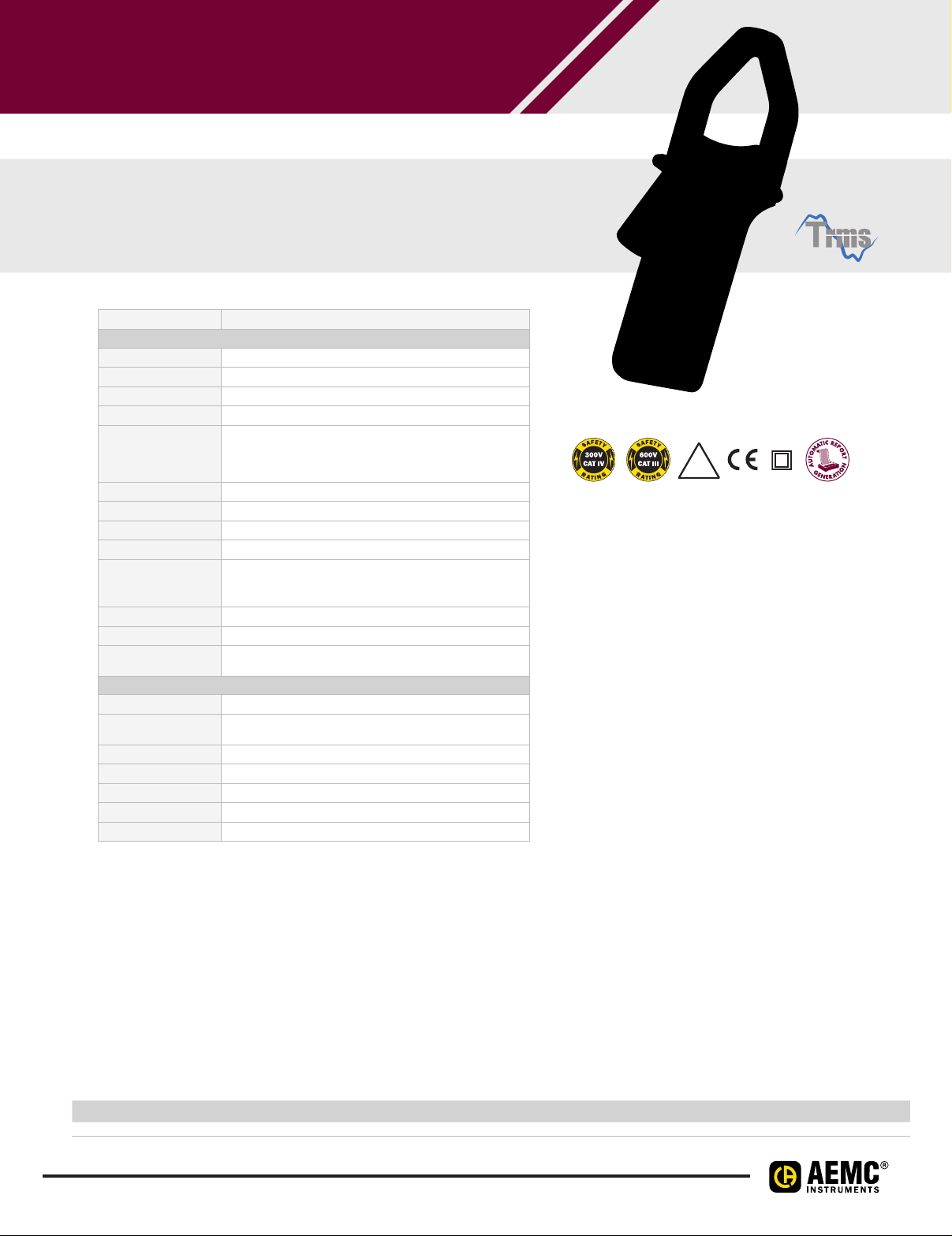
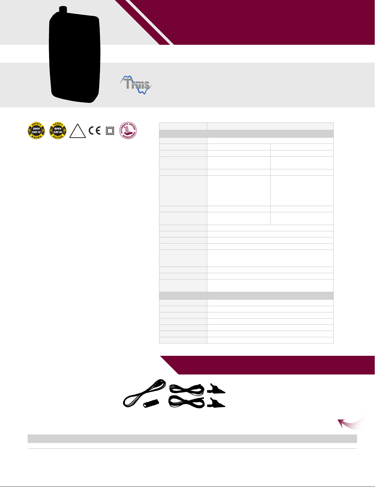
SIMPLE LOGGER® II TRMS CLAMPON CURRENT
MODEL CL
Designed for plant and field service
applications and for use in harsh environments
SPECIFICATIONS
MODEL CL
ELECTRICAL
Channels One
Input Split CT – AC Current
Measurement Range 0 to 600A
Resolution 0.1A
Accuracy (50/60Hz) 0 to 5A: unspecified
Sample Rate 64 samples/cycle
Storage Rate Programmable from 8 every second to 1 every day
Storage Modes Start/Stop, FIFO, Ex tended Recording Mode (XRM™)* and Alarm
Recording Length 15 minutes to 8 weeks, programmable using DataView
Memory
Communication USB 2.0 optically isolated
Power Source 2 x 1.5V AA-cell Alkaline batteries (included)
Battery Life 100 hours to >45 days
MECHANICAL
Dimensions 9.25 x 4.0 x 1.63" (235 x 102 x 41mm)
Max Conductor Size 1 conductor - Ø 1.42" (36mm)
Weight (with battery) 17.1oz (485g)
Case UL94-V0
Vibration IEC 68-2-6 (1.5mm, 10 to 55Hz)
Shock IEC 68-2-27 (30G)
Drop IEC 68-2-32 (1m)
*EXTENDED RECORDING MODE (XRM™)
240,000 measurements (512KB) - The recorded data is
stored in non-volatile memory and will be retained even if the battery
5 to 50A: ±(1% of Reading + 1A)
50 to 400A: ±(1% of Reading + 0.5A)
400 to 600A: ±(3% of Reading + 1A)
is low or removed.
(dependent on sample rate and recording length)
2 conductor s- Ø 1.00" (25mm) each
This unique recording mode provides the opportunity to
continuously record over long periods of time by reducing the
stored samples of the oldest data and maintaining matching
resolution for the newest data. Each time the memory fills
up using XRM™ every other of the oldest stored samples is
discarded making room for newer samples. This process
continues until the recording is manually stopped.
ac
®
IP
40
FEATURES
• 0 to 600Arms
• True RMS measurements
• Self contained, no exposed connections
• Overload indication
• Optically isolated USB 2.0 communication
cable included
• One button operation
• Alarm function
• 5 LED indicators quickly and clearly display
logger status
• Powered by standard Alkaline batteries
• Includes FREE DataView
retrieval, real-time display, analysis and report
generation
• EN 61010-1; 300V CAT IV, 600V CAT III
®
software for data
APPLICATIONS
• Machine load monitoring
• HVAC troubleshooting
• Load profiling
• Electrical troubleshooting
• Start-Stop time stamping
CATALOG NO. DESCRIPTION
2126.01 Simple Logger® II Model CL601 (1-Channel, TRMS, Clamp-On, 0 to 600Aac, DataView® software)
36
Page 3
R
A
T
I
N
G
S
A
F
E
T
Y
IP
53
cover open
IP
65
cover closed
FEATURES
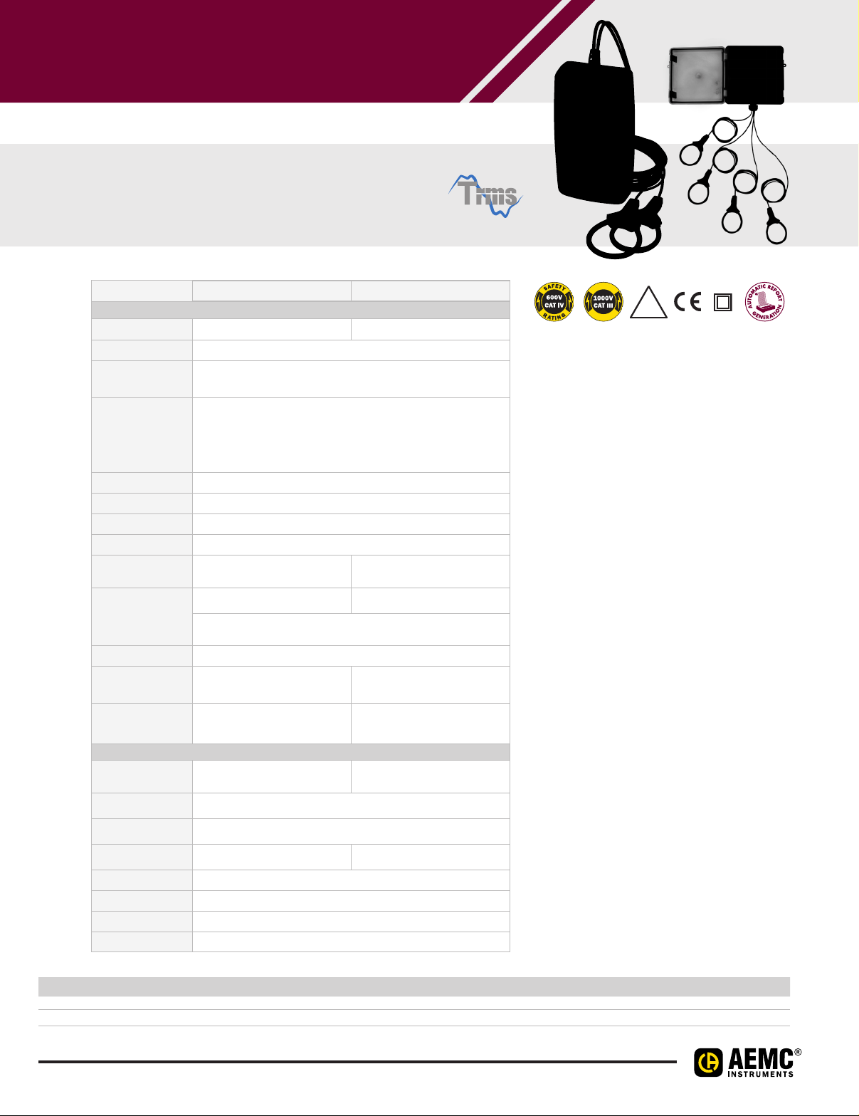
• Includes four integral AmpFlex® flexible current probes
that will measure up to 3000A TRMS with 0.5A
resolution
• Dual range 300/3000A user selectable per channel
• 64 samples per cycle
• Programmable storage rates from 125ms to 1 per day
• 4 user selectable storage modes
• Stores up to 1,000,000 measurements in non-volatile
memory
• Powered by standard Alkaline batteries for a period
of up to 180 days
• Lightweight, compact and watertight
• 6 LED indicators quickly and clearly display
logger status
• Wireless Bluetooth data communication (Class 2
Bluetooth module included)
• Includes FREE DataView
®
software for data storage,
real-time display, analysis and report generation
• EN 61010-1; 600V CAT IV, 1000V CAT III
APPLICATIONS
• Single/Split-phase and 3-phase load monitoring
• Neutral and ground current monitoring
• Intermittent problem detection
• Harmonic current monitoring using
DataView
• Machine load monitoring
• Fault current detection
• Load profiling
®
software
DATA LOGGERS
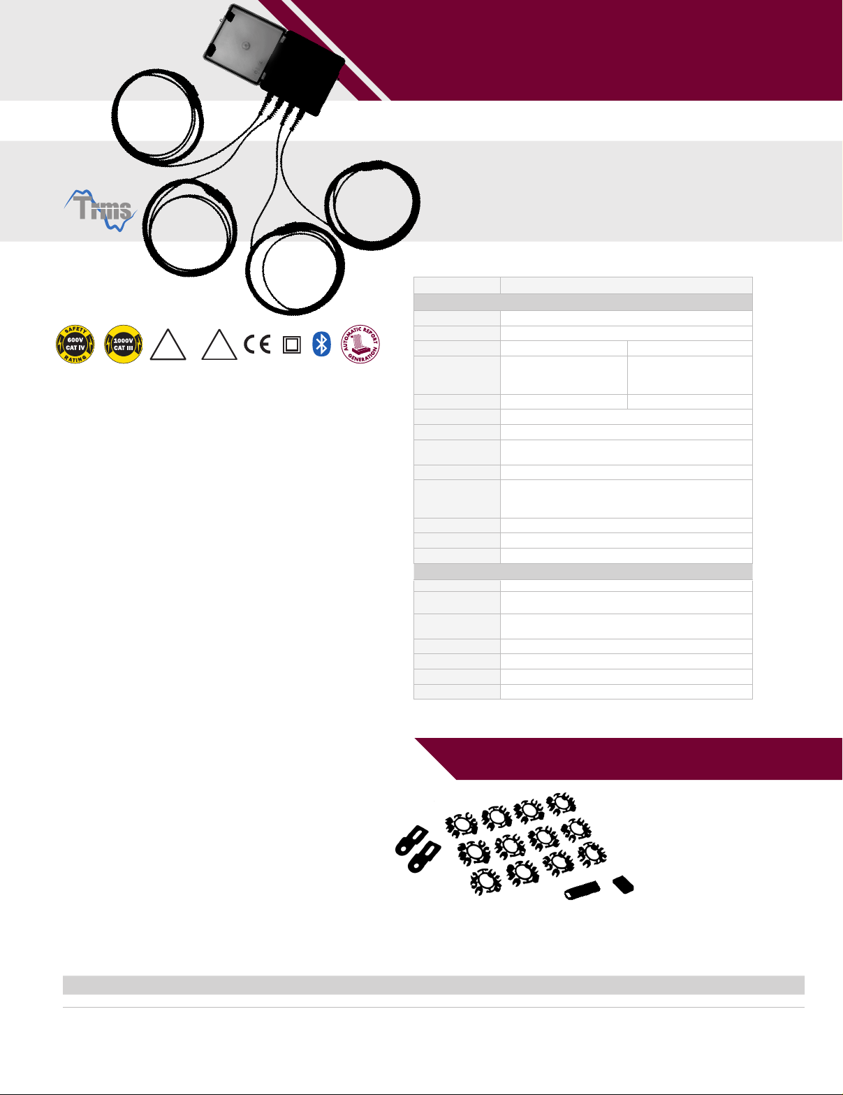
SIMPLE LOGGER® II CHANNEL BLUETOOTH EDITION
CHANNEL AMPFLEX® MODEL AL
Four channel logger with 24" long
flexible sensors capable of wrapping
around an 8" conductor
SPECIFICATIONS
MODEL AL
ELECTRICAL
Channels Four
Input Captive AmpFlex® AC Current Flexible Sensors
Range 5 to 300A
Accuracy
(50/60Hz)
Resolution 0.1A
Sample Rate 64 samples/cycle
Storage Rate Programmable from 125ms to 1 per day
Storage Modes
Recording Length 15 minutes to 8 weeks, programmable using DataView
Memory
Communication Bluetooth connection (communicates up to 30 ft)
Power Source 4 x 1.5V C-cell Alkaline batteries (included)
Battery Life Up to 180 days (dependent on storage rate/recording length)
0 to 5A unspecified
±(1% of Reading + 0.5A)
Start/Stop, FIFO, Ex tended Recording Mode (XRM™),
The recorded data is stored in non-volatile memory and will be
MECHANICAL
Dimensions 5.904 x 5.904 x 3.568" (150 x 150 x 91mm) w/o Sensor
Max Conductor Size
Weight
(with battery)
Case UL94-V0
Vibration IEC 68-2-6 (1.5mm, 10 to 55Hz)
Shock IEC 68-2-27 (30G)
Drop IEC 68-2-32 (1m)
ac 15 to 3000Aac
5 to 300A:
ac 0.5Aac
Store on Alarm
1,000,000 measurements (2MB)
retained even if the battery is low or removed.
Ø 8" (203mm)
3.9 lbs (1.77kg)
0 to 15A unspecified
15 to 3000A:
±(1% of Reading + 1A)
PRODUCT INCLUDES
Bluetooth USB adapter, twelve
color-coded input ID markers,
mounting hardware, 4 x 1.5V
C-Cell Alkaline batteries, and USB
drive supplied with DataView®
software and user manual.
®
CATALOG NO. DESCRIPTION
21 26.1 4 Simple Logger® II Model AL834 (4-Channel, TRMS, Bluetooth, AmpFlex® 300/3000Aac, DataView® software)
37
Page 4
DATA LOGGERS
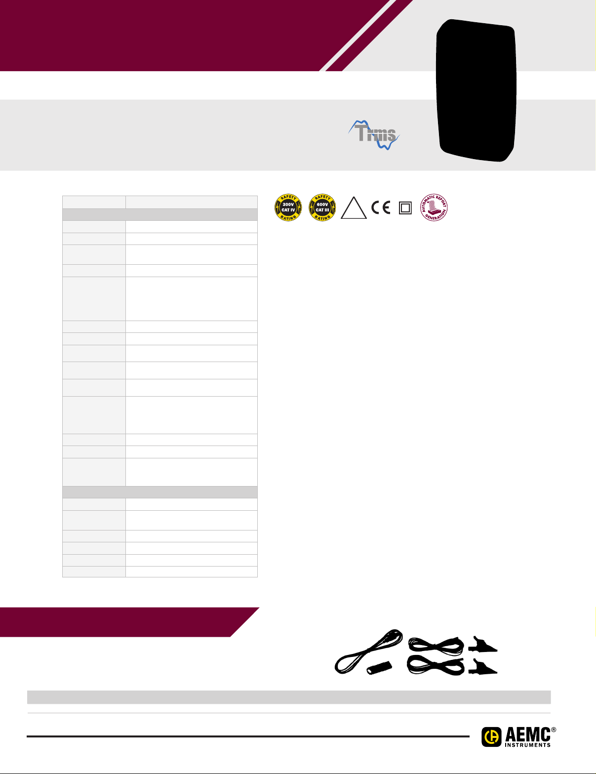
SIMPLE LOGGER® II TRMS VOLTAGE
VAC/DC MODEL L
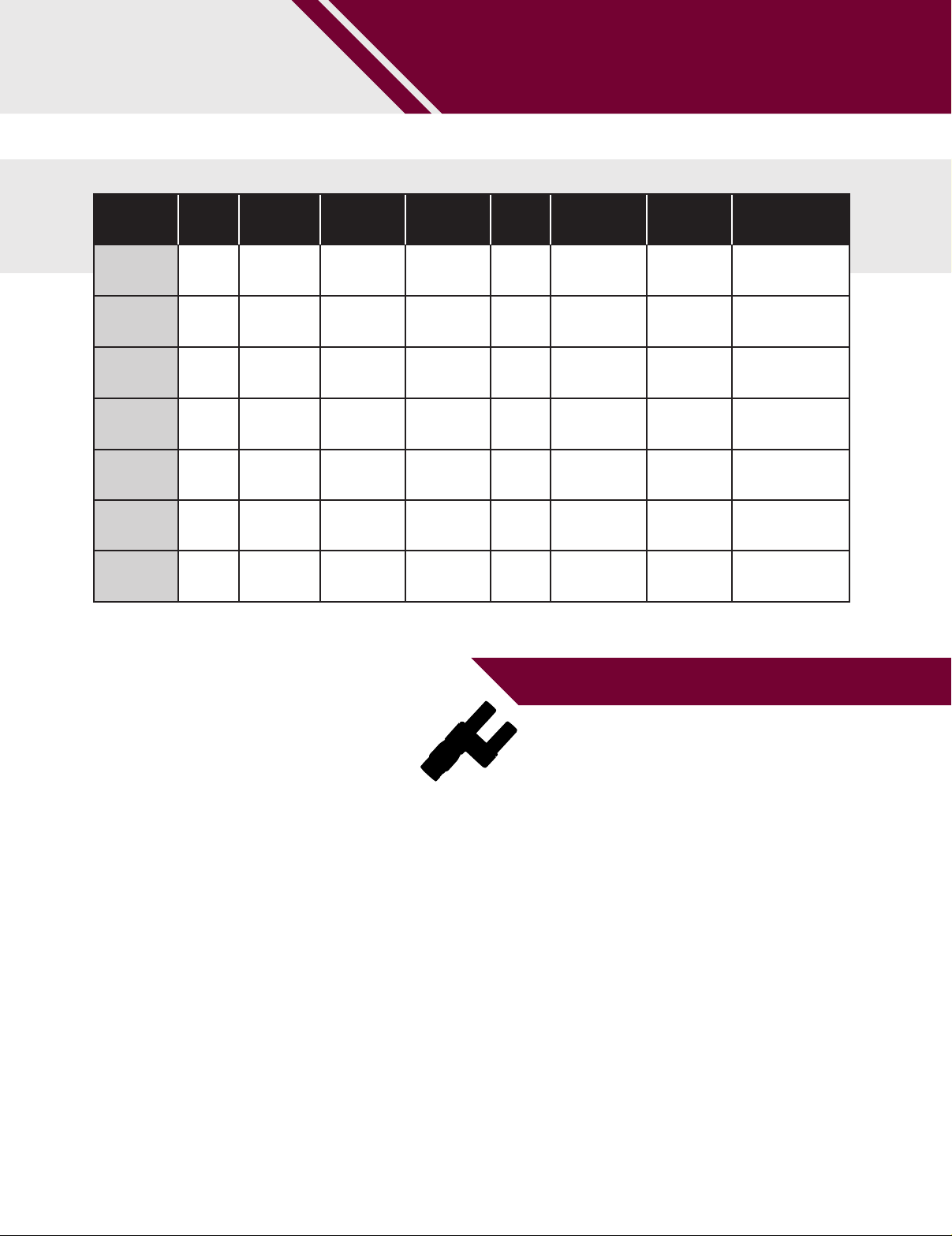
One channel loggers for voltage measuring,
monitoring and troubleshooting
SPECIFICATIONS
MODELS L
ELECTRICAL
Channels One
Input Connection Two recessed 4mm safety banana jacks
Measurement
Range
Resolution 0.1V
Accuracy
(50/60Hz)
Input Impedance 40MΩ
Sample Rate 64 samples/cycle
Storage Rate Programmable from 8 every second to 1 every
Storage Modes Start/Stop, FIFO, Ex tended Recording Mode
Recording Length 15 minutes to 8 weeks, programmable using
Memory 240,000 measurements (512KB)
Communication USB 2.0 optically isolated
Power Source 2 x 1.5V AA-cell Alkaline batteries (included)
Battery Life 100 hours to >45 days
MECHANICAL
Dimensions 4.94 x 2.75 x 1.28" (125 x 70 x 32mm)
Weight
(with battery)
Case UL94-V0
Vibration IEC 68-2-6 (1.5mm, 10 to 55Hz)
Shock IEC 68-2-27 (30G)
Drop IEC 68-2-32 (1m)
The recorded data is stored in non-volatile
memory and will be retained even if the battery
0 to 5V: unspecified
±(0.5% of Reading + 1V)
±(0.5% of Reading + 0.5V)
(XRM™) and Alarm
is low or removed.
(dependent on sample rate and recording
0 to 600V
5 to 50V:
50 to 600V:
day
DataView
length)
6.4oz (181g)
ac/dc
®
IP
40
FEATURES
• TRMS voltage recording up to 600VAC/DC
• AC: 64 samples per cycle and DC: 8 samples per sec
• Programmable storage rates from 8 every second to
1 every day
• 4 user selectable storage modes
• Stores up to 240,000 measurements in non-volatile memory
• Powered by standard Alkaline batteries
• Lightweight, compact, fits anywhere
• 5 LED indicators quickly and clearly display logger status
®
• Includes FREE DataView
software for data retrieval, real-time
display, analysis and report generation
• Optically isolated USB 2.0 communication cable included
• EN 61010-1; 300V CAT IV; 600V CAT III
APPLICATIONS
• Surge and Sag recording
• Long term supply monitoring
• Industrial, commercial and residential monitoring
• Monitor voltage harmonics
• Find intermittent voltage problems
• Machine monitoring
PRODUCT INCLUDES
Set of two color-coded 5ft voltage leads, color-coded alligator
clips (red/black), USB type A to 5 pin Mini-B, and USB drive
supplied with DataView® software and user manual.
CATALOG NO. DESCRIPTION
2126.05 Simple Logger® II Model L261 (1-Channel, TRMS, 600Vac/dc, DataView® software)
38
Page 5
IP
40
FEATURES
• 2 input channels
• Voltage: 0 to 600V
• Current: compatible with voltage output AC
current probes with voltage outputs
(see page 33 - sold separately)
• 64 samples per cycle
• Records Arms, Vrms & VA
(VA displays in DataView
• 4 user selectable storage modes
• Programmable storage rates from 8 every
second to 1 every day
• Stores up to 240,000 measurements in
non-volatile memory
• Powered by standard Alkaline batteries
• Lightweight, compact, fits anywhere
• 5 LED indicators quickly and clearly display
logger status
• Includes FREE DataView
retrieval, real-time display, analysis and report
generation
• Optically isolated USB 2.0 communication
cable included
• Complies with EN 61010-1; 300V CAT IV; 600V
CAT III (a safety rated current probe is required)
AC TRMS
®
software)
®
software for data
DATA LOGGERS
SIMPLE LOGGER® II TRMS VOLTAGE & CURRENT
MODEL L
Two input channel logger capable of
recording Arms, Vrms and VA
SPECIFICATIONS
MODEL L
ELECTRICAL
Channels Two
Connection Current Channel Voltage Channel
Input Connection BNC Two recessed banana jacks
Input Range 0 to 1Vac (for use with current probes
Resolution 0.1mV 0.1V
Accuracy (50/60Hz) 0 to 10mV unspecified
Input Impedance 800kΩ 40MΩ
Maximum
Input Voltage
Sample Rate 64 samples/cycle
Storage Rate Programmable from 8 every second to 1 every day
Storage Modes Start/Stop, FIFO, Extended Recording Mode (XRm
Recording Length 15 minutes to 8 weeks, programmable using DataView®
Memory 240,000 measurement (512KB).
Communication USB 2.0 optically isolated
Power Source 2 x 1.5V AA-cell Alkaline batteries (included)
Battery Life 100 hours to > 45 days
MECHANICAL
Dimensions 5.38 x 2.75 x 1.28" (136 x 70 x 32mm)
Max Conductor Size Current probe dependent
Weight (with battery) 6.4oz (181g)
Case UL94-VO
Vibration IEC 68-2-6 (1.5mm, 10 to 55Hz)
Shock IEC 68-2-27 (30G)
Drop IEC 68-2-32 (1m)
with a voltage output)
0 to 5V unspecified
10 to 50mV:
±(0.5% of Reading + 1mV)
50 to 1000mV:
±(0.5% of Reading + 0.5mV)
5Vrms or ±7.07V peak 1.2 x 600V
The recorded data is stored in non-volatile memory and
will be retained even if the battery is low or removed.
(dependent on sample rate and recording length)
±(0.5% of Reading + 1V)
±(0.5% of Reading + 0.5V)
ac
0 to 600V
5 to 50V:
50 to 600V:
TM
) and Alarm
APPLICATIONS
• Single phase power monitoring
• Residential, commercial, industrial,
troubleshooting
• Find sags and surges
• Track energy usage
• Start-Stop time stamping
SEE PAGE FOR COMPATIBLE CURRENT PROBES SOLD SEPARATELY
CATALOG NO. DESCRIPTION
2126.35 Simple Logger® II Model L562 (2-Channel, TRMS, Voltage & Current, DataView® software)
39
Mini-B, and USB drive supplied with
DataView® software and user manual.
PRODUCT INCLUDES
Set of two color-coded 5ft voltage
leads, color-coded alligator clips
(red/black), USB type A to 5 pin
Page 6
DATA LOGGERS
R
A
T
I
N
G
S
A
F
E
T
Y
SIMPLE LOGGER® II TRMS VOLTAGE
MINIFLEX® MODELS ML & ML
AC current recording loggers
incorporate two selectable
measurement ranges
SPECIFICATIONS
MODEL ML ML
ELECTRICAL
Channels Two Four
Input Captive MiniFlex
Range
Accuracy (50/60Hz)
Resolution 0.1A
Sample Rate 64 samples/cycle
Storage Rate Programmable from 8 every second to 1 every day
Storage Modes Start/Stop, FIFO, Extended Recording Mode (XRM™) and Alarm
Recording Length
Memory
Communication USB 2.0 optically isolated
Power Source
Battery Life
(100A Range)
(1000A Range)
15 minutes to 8 weeks,
programmable using DataView®
240,000 measurement (512KB) 1,000,000 measurement (2MB)
The recorded data is stored in non-volatile memory
and will be retained even if the battery is low or removed.
2 x 1.5V AA-cell Alkaline batteries
(included)
100 hrs to >45 days
(dependent on storage
rate/recording length)
MECHANICAL
Dimensions
Max Conductor Size
Cable Length
Weight (with battery)
Case UL94-V0
Vibration IEC 68-2-6 (1.5mm, 10 to 55Hz)
Shock IEC 68-2-27 (30G)
Drop IEC 68-2-32 (1m)
4.95 x 2.75 x 1.28" (136 x 70 x 32mm)
w/o Sensor
8.67oz (245g) 2.4lbs (1.1kg)
®
AC Current Flexible Sensors
1 to 100A
ac
5 to 1000Aac
0 to 1A unspecified
1 to 100A: ±(1% of Reading + 0.5A)
5 to 1000A: ±(1% of Reading + 1A)
0 to 5A unspecified
200 hours to 180 days,
programmable using DataView®
4 x 1.5V C-cell Alkaline batteries
Up to 180 days
(dependent on storage
rate/recording length)
5.904 x 5.904 x 3.568" (150 x 150 x 91mm)
Sensor: 6" (152mm)
6ft (2m)
(included)
w/o Sensor
IP
40
FEATURES
• Includes two or four integral MiniFlex® flexible
current probes that will measure from 1A to
1000A TRMS with 0.1A resolution
• Dual range 100/1000A user selectable per
channel in software
• 64 samples per cycle
• Programmable storage rates from 8 every
second to 1 every day
• 4 user selectable storage modes
• ML912 stores up to 240,000 measurements
in non-volatile memory and ML914 stores
up to 1,000,000 measurements
• Powered by standard Alkaline batteries
• Lightweight, compact, fits anywhere
• 5 LED indicators quickly and clearly display
logger status
• Includes FREE DataView
®
software for data
retrieval, real-time display, analysis and
report generation
• Optically isolated USB 2.0 communication
cable included
• EN 61010-1; 600V CAT IV, 1000V CAT III
APPLICATIONS
• Single and Split phase load monitoring
• Neutral and ground current monitoring
• Intermittent problem detection
• Harmonic current monitoring using
DataView
• Machine load monitoring
• Fault current detection
• Load profiling
®
software
CATALOG NO. DESCRIPTION
2126.37 Simple Logger® II Model ML912 (2-Channel, TRMS, Bluetooth, MiniFlex®, 100/1000Aac, DataView® software)
2126.40 Simple Logger® II Model ML914 (4-Channel, TRMS, Bluetooth, MiniFlex®, 100/1000A
40
ac, DataView
®
software)
Page 7
DATA LOGGERS
SIMPLE LOGGER® II TRMS VOLTAGE
PROBE SELECTION CHART FOR MODEL L
AEMC
MODEL
NUMBER
MN261 2115.82
MF 300-6-2-10 2126.81
1000-24-2-1 2112.98
MN251 2115.7 7 1mV/A
MN379T 2153.02
SR661 2113.49
JM861 2110.90
AEMC
CATA LOG
NUMBER
PROBE
OUTPUT
100mV/A
10mV/A
100mV/A
10mV/A
10 mV/a
1mV/A
ac 0.5 to 240A 240A
200mV/A
10mV/A
1mV/A
10mV/A
100mV/A
10mV/A
1mV/A
0.1mV/A
PROBE
RANGE
0.1 to 24A
0.5 to 240A
30A
300A
5 to 100A
5 to 1000A
5A
100A
1000A
100A
10A
1 to 30A
1 to 300A
1 to 3000A
MAX RANGE
FOR SLII
10A
100A
10A
100A
100A
1000A
5A
100A
1000A
100A
10A
30A
300A
3000A
CABLE
DIAMETER
0.78"
(19.8mm)
1.77"
(44.96mm)
8"
(203.2mm)
0.78"
(19.81mm)
0.78"
(19.8mm)
2.13"
(54.1mm)
2.52"
(64.01mm)
BUS BAR
SIZE
N/A Lead w/BNC —
2.25 x 0.75"
(57.15 x 19.05mm)
N/A
N/A
N/A Lead w/BNC —
N/A BNC —
1.97 x 5.31"
(50.03 x 134.87mm)
OUTPUT
CONNECTION
Sensor w/BNC —
Sensor
w/Banana Plugs
Lead
w/Banana Plug
Lead w/BNC —
NOTES
Must use adapter
# 2118.46
Must use adapter
# 2118.46
OPTIONAL ACCESSORY
Banana (female) BNC (male) (XM-BB)
Catalog #2118.46
(use with probes that have banana plug outputs
to connect to a Model L562)
41
Page 8
DATA LOGGERS
TWOCHANNEL DC VOLTAGE, CURRENT,
PULSE & EVENT
MODEL L
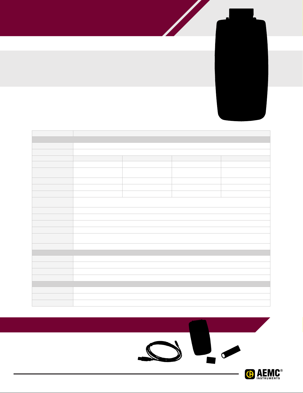
Bluetooth-enabled logger and
event counter that records DC voltage, DC current,
4 to 20mA or pulse counts
Real-time display!
Powered by batteries or through a USB cable
SPECIFICATIONS
MODEL L
ELECTRICAL
Channels Two*
Input Six-pin terminal strip
Measurements DC Current DC Voltage Event Pulse
Range 4 to 20mA 100mV, 1V, 10V N/A N/A
Accuracy
(% of Reading)
Resolution 0.01mA 0.1mV, 1mV, 10mV N/A N/A
Input Impedance 100Ω 1MΩ 1MΩ N/A
Sample Rate 5 samples/s 5 samples/s 16 samples/s 100 samples/s
Sample Period
Storage Modes Start/Stop (ends when memory is full or when the recording stop time is reached, whichever comes first)
Recording Length 10 minutes to 1 year, set via instrument front panel or through DataView
Memory 32MB internal Flash memory (up to 1024 logging sessions, 16M samples)
Communication Bluetooth 2.1, Class 1 or USB 2.0
Power Source
Battery Life Up to 180 days (dependent on storage rate/recording length)
MECHANICAL
Dimensions 1.275 x 2.578 x 5.413" (32.4 x 65.5 x 137.5mm)
Weight (with battery) 6.7oz (190g) with batteries
Vibration IEC 68-2-6 (1.5mm, 10 to 55Hz)
Shock IEC 68-2-27 (30G)
ENVIRONMENTAL
Operating Temperature 32° to 122°F (0° to 50°C)
Humidity 16 to 85%
Protection IP40 (instrument alone); IP20 (instrument with terminal strip)
*Both channels must have the same input type.
±(0.25% + 5cts) ±(0.5% + 1ct) N/A N/A
DC inputs: 200, 400, 600, or 800ms; or from 1 to 60 seconds
Pulse detection: 10ms
®
External: via USB connector
Internal: 2 x AA NIMH rechargeable batteries (charges through USB port)
42
PRODUCT INCLUDES
6ft USB cable, US 120V wall-to-USB
plug, 6-pin screw terminal block, 2 x
AA rechargeable NiMH batteries, quick
start guide, and a USB drive containing
DataView® software and a user manual.
Page 9
DATA LOGGERS
TWOCHANNEL DC VOLTAGE, CURRENT,
PULSE & EVENT
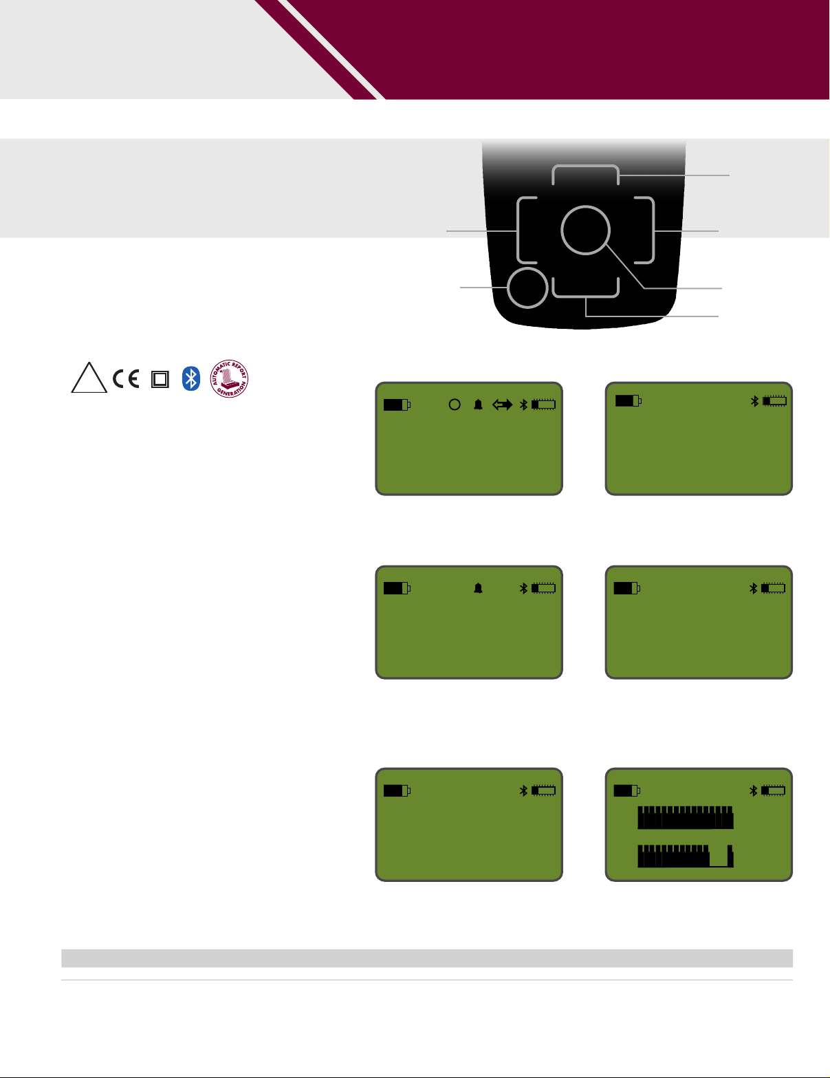
Front Panel & Functional Displays
IP
20
with terminals
FEATURES
• Multiple data input types. The L452
can log DC voltage, DC current, 4 to
20mA pulse counts, or events.
Measurements can be performed
directly on the instrument, or through a
variety of sensors. This data is stored in
the instrument’s large 32MB internal
Flash memory.
• Expanded user interface. You can set
up the instrument and view real-time
measurement data through the front
panel LCD screen and input buttons.
The L452 features an on-board menubased interface for navigating
measurement data and selecting
configuration options.
®
• Enhanced DataView
instrument connects to a PC using
either Bluetooth or USB. Once
connected, logged data can be
downloaded, analyzed, and formatted
into reports using DataView’s new
Data Logger Control Panel. This
Control Panel also enables users to
change settings on the instrument,
view real-time measurements,
schedule recording sessions, and
perform other configuration tasks.
support. The
Navigation
button: Left
Power ON/OFF
button
INSTRUMENT CONFIGURATION
OL
1
2
Instrument configuration parameters can be set
through the front panel interface.
ALARM
24.5
91.8
TRIGGERS
mV
mV
UPPER LIMIT:
50.00 degC
LOWER LIMIT:
-10.00 degC
Allows you to set the upper and/or lower alarm
trigger limits.
MIN/MAX MEASUREMENTS
1
For analog input types, this screen displays
the session’s MIN/MAX measurement values for
each channel.
MAX
MIN
2.54
2.54
0.22
m3/s
m3/s
m3/s
Navigation
button: Up
Navigation
button: Right
Enter button
Navigation
button: Down
BLUETOOTH ENABLED/VISIBILITY
Bluetooth:
Enabled
Visibility:
Visible
Enable and configure Bluetooth's functionality.
RECORDING SESSION
RECORDING
SESSIONS: 4
FREE
MEMORY: 29.66 MB
Displays the number of recording sessions
currently stored in memory. It also shows the
amount of free memory left for storing additional
recording sessions.
EVENT MEASUREMENT DATA
1
2
For event input, the Channels 1 & 2
measurement graphic data screen appears.
CATALOG NO. DESCRIPTION
2153.51
Data Logger Model L452 (2-Channel, w/LCD, 100mV/1V/10V
& Pulse, DataView
®
software)
dc, 4 to 20mAdc, Event
43
Page 10
DATA LOGGERS
TO CHANNEL LOGGER
MODELS DL & DL
Versatile, powerful and cost effective data loggers
handling analog, digital and other types of variables
with high resolution and speed
SPECIFICATIONS
MODELS DL & DL
ELECTRICAL
Input Type Measuring Range: Accuracy:
Linear 0 to 20mA
Linear 4 to 20mA
Linear 0 to 20mV
Linear 0 to 50mV
Linear 0 to 60mV
Linear -20 to 20mV
Linear 0 to 5V
Digital Inputs
Internal Memory 2MB
Excitation Current Pt100s: 360µA; ; Pt1000s: 320µA
Maximum Pt100/Pt1000
Compensated Cable
Resistance
Maximum Input Voltage 30Vdc
Input Current @ 30Vdc
(typical)
Digital Outputs
Storage Rate from 1ms to 24 hours
Maximum Channel Logged 100
Supported Modbus
Commands
Power Supply 100 to 240V
ENVIRONMENTAL
Operating Temperature 32° to 122°F (0° to 50°C)
Relative Humidity
Altitude < 6500ft (2000m)
Protection IP20
F.R. = Full Range
*The full scale refers to the input of the sensor signal and not the range of configured indication.
Linear 0 to 10V
J -184º to 1832ºF (-120º to 1000ºC)
K -202º to 2501.6ºF (-130º to 1372ºC)
T -202º to 752ºF (-130º to 400ºC)
E -202º to 1436ºF (-130º to 780ºC)
N -202º to 2372ºF (-130º to 1300ºC)
R 68º to 3214.4ºF (20º to 1768ºC)
B 212º to 3308°F (100º to 1820ºC)
Pt100 -328º to 1562ºF (-200º to 850ºC)
Pt1000 -328º to 1562ºF (-200º to 850ºC)
User Programmable ±0.15% (F.R.)*
Logic level “0”: from 0 to 0.8V
Logic level “1”: from 3 to 30Vdc
40Ω
3mA
Maximum output voltage: 30V
Maximum output current: 200mA
Maximum relay current: 3A @ 250Vac; 3A @ 30Vdc
Read Coil Status (01h)
Read Holding Registers (03h)
Write Single Coil (05h)
Write Single Register (06h)
Write Multiple Registers (0Fh)
ac, 50/60Hz. 20VA (max)
80% up to 85°F (30°C)
For temperatures higher than 85°F (30°C),
decrease 3% per °C
±0.2% (F.R.) ±1ºC
±0.2% (F.R.) ±3ºCS 68º to 3214.4ºF (20º to 1768ºC)
±0.15% (F.R.)
dc
dc
INPUTS RATED CAT II
IP
20
FEATURES
• 8 universal analog input channels
• 8 digital I/Os (individually configured as
inputs or outputs)
• 2 relay outputs (NO, NC and common)
• RS485 interface (Modbus master
or slave)
• 24Vdc output to power up to eight 4 to
20mA transmitters
• Ethernet interface for LAN and
internet use
• USB-device interface for configuring,
monitoring and download
• USB-host interface for logged data
retrieval through a USB flash drive
• Up to 32 configurable alarms
• Up to 128 virtual channels
• Detachable display (optional)
• Up to 100 channels can be logged at a
configurable rate
• Includes FREE software for data
retrieval, real-time display, analysis and
report generation
• 4 input channel types: analog, digital,
remoted and virtual
• Up to 16GB SD card interface
44
Page 11

DATA LOGGERS
TO CHANNEL LOGGER
MODEL DL
"FAVORITES" SCREEN
Shows a six-position grid where you can assign
a channel to be displayed real-time
in each position.
"CONFIGURATION" SCREEN
Color Functional Displays
"CHART" SCREEN
Displays a plot of the favorite
channels values.
"ALARMS" SCREEN
SOFTWARE SCREENS
Data logger and display parameters can be
changed and viewed on this screen.
A 32-position grid where each numbered position is related to its equivalent alarm or event.
When an alarm is active, its number will be
displayed in red on this screen.
PRODUCT INCLUDES
DL-1080 & DL-1081 SOFTWARE
USB drive supplied with software,
drivers and user manual
CATALOG NO. DESCRIPTION
2134.61 Data Logger Model DL-1080 (8 Analog to 8 Digital Channel, no LCD)
2134.62 Data Logger Model DL-1081 (8 Analog to 8 Digital Channel, LCD)
45
Page 12
DATA LOGGERS
40
SIMPLE LOGGER® DATA LOGGERS
MODELS SL TO SL
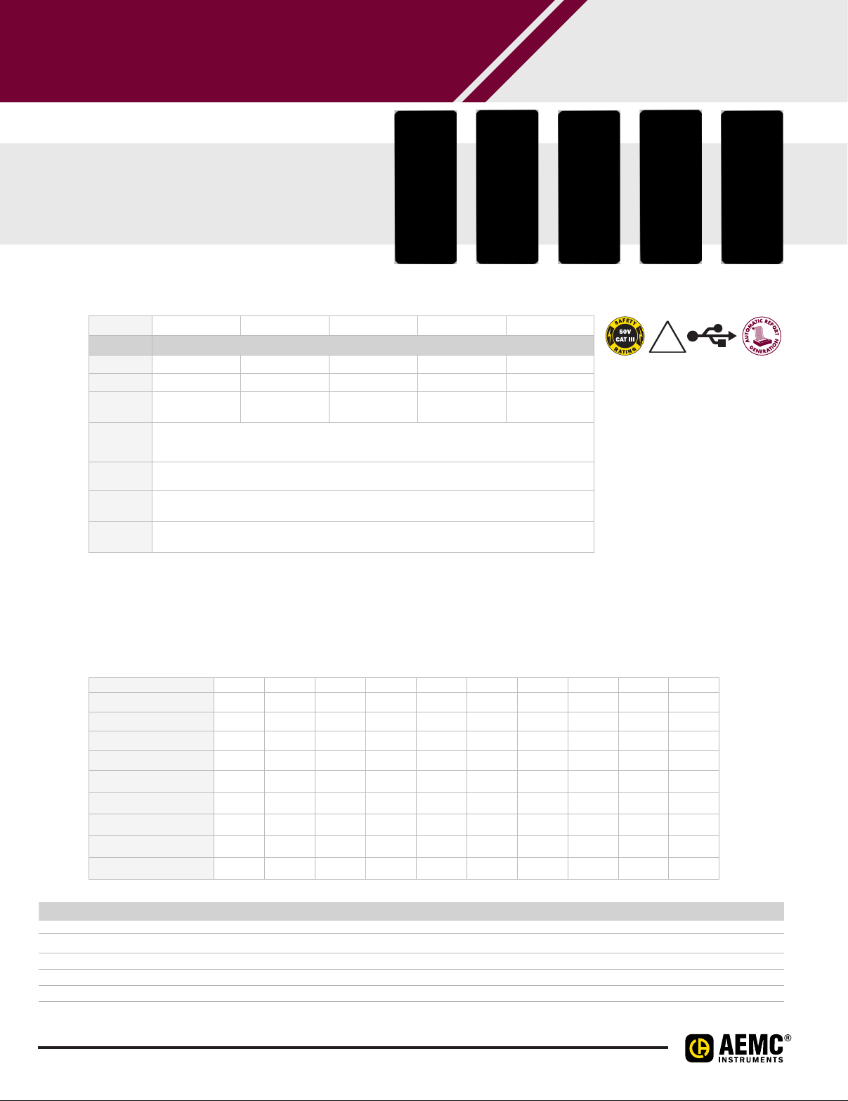
These small AC and DC simple
loggers can be ready to go in minutes
with just a few parameters to set up
Model SL01
Model SL10
Model SL11
Model SL12 Model SL13
SPECIFICATIONS
MODELS SL01 SL10 SL11 SL12 SL13
VOLTAGE
Range 0 to 5 VAC ±100 mVDC ±1 VDC ±10 VDC ±50 VDC
Resolution 10 mV 0.1 mV 1 mV 1 0 mV 50 mV
Accuracy
Maximum
Input
Voltage
Input
Impedance
Power
Source
Power
Consumption
±(0.5% of reading +
50 mV)*
±(0.5% of reading +
0.5 mV)*
Internal: Two 1.5 V AA non-rechargeable batteries
External: USB 2.0 (computer or other USB power source)
±(0.5% of reading +
5 mV)*
60 V
DC
800 KΩ
Internal power: 1 mA (average)
External power: 100 mW
±(0.5% of reading +
50 mV)*
±(0.5% of reading +
250 mV)*
FEATURES
• Simple 1 button operation
• Quick 2 wire input connection
• User configurable scaling, units
of measure and recording length
• Stores up to 4 million
measurements
• Data analysis software included
• Software provides real-time
trend graph display, data
download, analysis and report
generation
• Micro-B USB cable included
The Simple Logger Control Panel allows you to configure how data measured by these instruments is recorded
and displayed. The available settings depend on which model is connected to the computer. The following table
shows which configuration options are available for each model.
IP
FEATURE SL01 SL10 SL11 SL12 SL13 SL20 SL30 SL31 SL40 SL50
Set up recording
Define units
Set instrument clock
Erase instrument memory
Scaling
Filtering
Thermocouple type
Cold Junction Compensation
Rising/Falling events
CATALOG NO. DESCRIPTION
2156.01 Simple Logger Model SL01 (Voltage, 5 VAC)
2156.10 Simple Logger Model SL10 (Voltage, 100mV
2156.11 Simple Logger Model SL11 (Voltage, 1 V
2156.12 Simple Logger Model SL12 (Voltage, 10 V
2156.13 Simple Logger Model SL13 (Voltage, 50 V
46
DC)
DC)
DC)
DC)
Page 13
DATA LOGGERS
SIMPLE LOGGER® DATA LOGGERS
MODELS SL TO SL
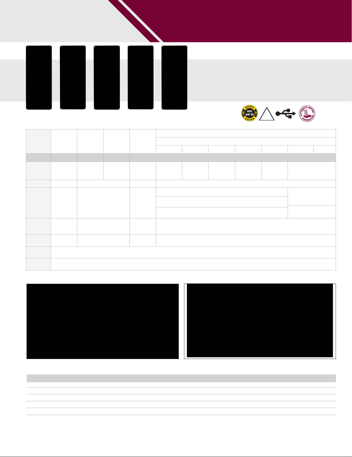
Models available for logging
DC Current, Temperature,
Pulse and Events
Model SL20
Model SL30
Model SL31
Model SL40 Model SL50
SPECIFICATIONS
MODELS SL20 SL30 SL31 SL40
J K N T E R S
CURRENT PULSE EVENT TEMPERATURE
Range ±20 mA
Resolution 0.02 mA n/a 0.1°C 0.1°C
Accuracy
Maximum
Input
Voltage
Input
Impedance
Power
Source
Power
Consumption
±(0.5% of
reading +
0.1 mA)*
3 VDC 10 VDC n/a 1 V
49 Ω 800 KΩ n/a 800 KΩ
Internal: Two 1.5 V AA non-rechargeable batteries External: USB 2.0 (computer or other power source, when powered by the USB the battery is automatically disconnected)
Contact
closure,
0 to 5 VDC
n/a
Contact
closure,
0 to 5 VDC
-94 to 1022°F
(-70C to
+550C)
±(1% of
reading + 1.8°F
[1°C])*
Internal power: 1 mA (average) External power: 100 mW
-346 to 2192°F
(-210 to
1200°C)
-328 to 2502°F
(-200 to
1372°C)
Below -148°F (-100°C): ±(0.4% of reading + 9°F [5°C])*
-148 to 212°F (-100° to 100°C): ±(0.3% of reading + 7.2°F [4°C])*
Above 212°F (100°C): ±(0.2% of reading + 5.4°F [3°C])*
SESSION PARAMETER REALTIME TREND GRAPH
Thermocouple Type:
-328 to 2372°F
(-200 to
1300°C)
-328 to 752°F
SL50
(-200 to
400°C)
IP
40
-328 to 1832°F
(-200 to
1000°C)
32 to 3200°F
(0 to 1760°C)
32 to 212°F (0° to +100°C):
±(0.3% of reading + 18°F
[10°C])*
Above 212°F (100°C): ±(0.2%
of reading + 14°F [8°C])*
Shows the current configuration of the logger.
CATALOG NO. DESCRIPTION
2156.20 Simple Logger Model SL20 (Current, 4 to 20 mADC)
2156.30 Simple Logger Model SL30 (Pulse)
2156.31 Simple Logger Model SL31 (Event)
2156.40 Simple Logger Model SL40 (Temperature, RTD/PT1000)
2156.50 Simple Logger Model SL50 (Temperature, Thermocouple)
47
Typical real-time trend graph.
Page 14
DATA ANALYSIS & REPORTING SOFTWARE
USE DATAVIEW® TO CONFIGURE ALL USER SELECTABLE FUNCTIONS ON
MODELS CL, AL, L, L, ML, ML, L
TYPICAL DATAVIEW®
FUNCTIONAL DISPLAYS
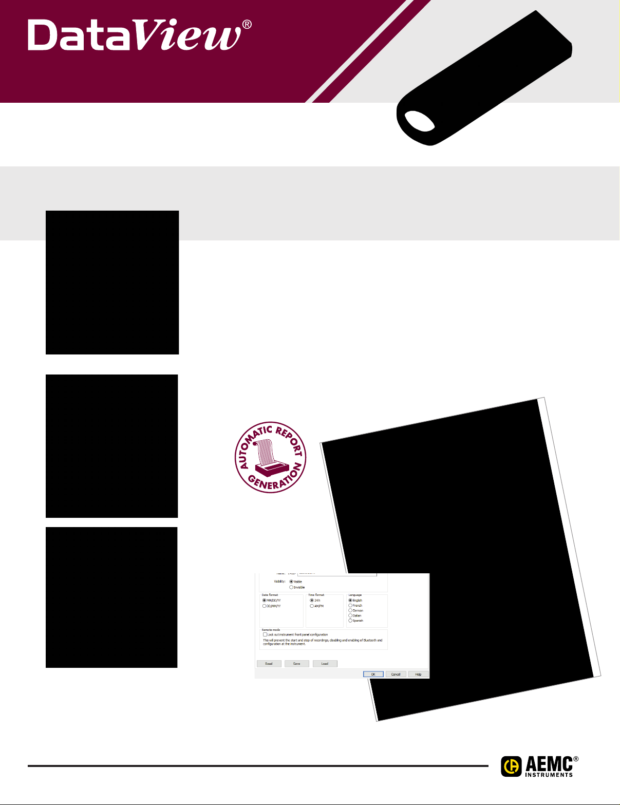
Quick and simple configuration of all functions
and settings from one dialog box.
CONFIGURE ALL DATA LOGGER FUNCTIONS
• Display and analyze real-time data on your PC
• Configure all data logger functions and parameters from your
PC including sample rate, recording length, channel configuration
and more
• Create and store a complete library of configurations that can be
uploaded to the logger as needed
• Zoom in and out and pan through sections of the graph to analyze
the data
• Download, display and analyze recorded data
• Display waveforms, trend graphs, harmonics (AC models) and
text summaries
• Create custom views and reports
• Print reports using standard or custom templates you design
• Free upgrade available from the help menu
48
 Loading...